effects of-lamination-packs-in-induction-heating-work-coil-design-by-the-superposition-method
TRANSCRIPT

ISSN: 2348 9510
International Journal Of Core Engineering & Management (IJCEM)
Volume 1, Issue 9, December 2014
1
Effects of Lamination Packs in Induction Heating Work Coil
Design by the Superposition Method
Dr. A.K.M. Al-Shaikhli Prof, Electrical Engineering DEPT, University of
Technology
Baghdad, Iraq
Mustafa F. Mohammed Assist. Lecturer, Ministry of Higher Education &
Scientific Research
Baghdad, Iraq
Email: [email protected]
Abstract— In some induction heating
applications, lamination packs are installed
around the coil. The main reason for using them
is to channel the flux in the region outside the
coil so that it does not link the surrounding
metallic objects, which will heat these objects
and, also, might result in sparking. The
efficiency will be improved also by the
employment of these flux guides due to the
reduction on the stray losses and the magnetizing
current. The object of this paper is to inspect the
applicability of the superposition method in a
system containing laminations, before this
technique can be recommended as a coil design
method to installations involving the
laminations. This is to be done by studying the
effect of the laminations on the power density
induced on the work piece due to single
conductor and number of conductors.
Keywords—Induction heating; lamination packs;Superposition.
I. INTRODUCTION
The employment of the ferromagnetic materials in
induction heating as a flux guide to protect the
surrounding metal work from being heated by the
stray flux is well known. Packs of low-loss materials,
such as nickel-iron or silicon-steel, are usually placed
on the outside of the coil of a vessel heater or melting
furnace, so as to confine the magnetic field close to
the outside of the coil. This prevents the flux from
spreading away from the outside of the coil and
linking with surrounding metallic objects.
The superposition method has been applied, to
rectangular and cylindrical work pieces [1]
successfully. The aim of this paper is to assess the
applicability of the superposition method on
applications whereby ferromagnetic laminations
exist in the system. This is done by investigating the
influence of these laminations on the distribution of
the power density induced on the load and, also, to
inspect the validity of the superposition method with
existence laminations.
II. SUPERPOSITION METHOD
This method considers the effect of each turn of the
coil, then applying the superposition principle to
determine the performance of the coil. This method
can be used to design a coil for applications requiring
non-uniform power density distribution along the
load. The theory of superposition method is
described in [2] and [3] and with the applicability of
it on a load of aluminum but without the effect of the
laminations. This paper is to show of applicability of
the superposition method on applications of

ISSN: 2348 9510
International Journal Of Core Engineering & Management (IJCEM)
Volume 1, Issue 9, December 2014
2
induction heating work coil design whereby
ferromagnetic laminations exist in the system.
If a circular conductor of radius (a) carrying current
(I) , at a distance (h) from the surface of semi-
infinite, good conductor slab, will induce magnetic
field strength at any point (P) along the surface of the
slab, given by:
HP =I
π×
he
he2+z2 (1)
Where:
ℎ𝑒 : The effective height = h2 − a2
Z: The distance along the slab, beneath the conductor
to point p
If there are (N) identical conductors instead of one
conductor, and the distance between the conductors
are constant and equal to d, i.e. uniform coil, then
HP =I . he
π
1
he2+(z1+xd )2
x=n−1 x=0 (2)
Also, it can be noticed that the magnetic field
intensity at the surface of the slab is equal to the
linear current density, A, induced per unit length of
the slab, see figure-1, i.e.
AP = HP (3)
It was found empirically, that the magnetic field of
equation (2) should be amended to the practical
equation below:
Figure-1 Number of identical conductors at a
specific air-gap from a metallic Load
H =β . I
π×
he
he2+
α
cos σz2
(4)
Where:
σ: The angle between the line joining the conductor
and point P and the perpendicular line from the
conductor to the slab.
Also, αandβ are constants found from practical
measurements and they are functions of the effective
heighthe . αis a straight line represented by:
α = 10−2he (5)
The application of the closet fit computer routine
was found to produce the equation of the other
constant β, where:
β = − 2.642 + 10−1 + 7.736 × 10⁻² he − 1.539 × 10⁻³ he
2 + 1.31 × 10⁻⁵ he3 − (3.968 ×
10−8)he4 (6)
Where he in (mm)
The variation of α and β is shown in figure-2 for
simplicity and within the accuracy levels required the
use of graphical results given in the figure is
preferred. From equation (3), it can be concluded that
the equation of induced current density is:
A =β . I
π×
he
he2+
α
cos σz2
(7)
Figure-2 the relations of ℎ𝑒 for different values of α
and β
III. EXPERIMENTAL WORK
The experiments were carried out on the same
aluminum slab employed in [1], and by using the
experimental rig as shown in figure-3 and its circuit
diagram as shown in[1],with the addition of the
laminations. The configuration of the system is
shown in figure-4. A pack of nickel-iron
laminations was used in the experiments; contained
250 sheets of the followingdimensions 45 ×280 ×
0.15mm. It was supported by 2 stainless steel bolts.

ISSN: 2348 9510
International Journal Of Core Engineering & Management (IJCEM)
Volume 1, Issue 9, December 2014
3
The pack was then covered with a Fiber glass tape
to maintain Proximity between the laminations and
to protect their edges. A Circular conductor of 28mm
diameter and a rectangular conductor were used in
order to investigate the laminations effect on a single
conductor.The air gap g between the aluminum slab
and the conductor was held constant at 40 mm. The
current in the conductor was permanently fixed at
1000A. The voltage induced at different points on
the load was measured by the current density probe
and the current distribution on the conductors was
also recorded, so that the effect of this distribution
could be assessed. When investigating the effect of
the laminations on the power density induced on the
load a pack of laminations was positioned above the
conductor at distance h1 = 5, 11, 20 and 35mm
respectively. The pack was above the center of the
aluminum slab, where the induced surface power
density was measured. Figures (5 & 6) show the
measurements of the induced surface power density
without the effect of lamination for circular and
rectangular conductors respectively while, figures (7,
8 , 9, & 10) show these measurements together with
the calculated values according to equation (7). The
differences between the two values did not exceed
5%; this proves that the practical equation (7) can be
used even when there are laminations above the
conductor. The constant α is the same as in the case
of no laminations, while the other constant β
increases when decreasing the distance h1, see
Table-1, Decreasing the distance h1 increases the
power density induced on the load i.e. increases the
coupling. Also, Table-2 shows the values of the
power density induced on the loaddirectly beneath
the conductor for different values of h1.
The next stage was to investigate the current
distribution on the conductor itself in order to find
out whether the change in the distribution of the
induced power density was due to a variation on the
conductor current distribution or not. The surface
current density distribution on the circular and
rectangular conductors was measured with the
laminations pack 5mm above it. It was found that
laminations do not have an important effect on the
distribution of the current on the conductor where,
this effect did not exceed 5% & 7% for circular and
rectangular conductors respectively. So it can be
conclude that the power induced on the load was
due mainly to the presence of the laminations. As
the power density induced underneath the pack has
already been investigated. It is important to know
the effect of the laminations on the parts of the load
which are not exactly beneath them. One lamination
pack was placed above one edge of the load and the
induced voltage distribution was measured at both
edges of the slab. The distance h1 was 5, 11, 20 and
35mm respectively.Figures (11, 12, 13, & 14)
illustrate the power density distribution for h1 =
35mm and h1 = 5mm only. The other results are
not shown because they lie between the limits of
these two cases. These curves show the power
density induced on two parts of the load, near the
two edges, one is covered with one pack of
laminations and the other edge is left exposed.
Figures (11 & 12) show that, within the range of the
experiments, the laminations do not have an
important effect on the distribution of the current on
the conductor. This effect did not exceed 5% for
the circular conductor and 7% for the rectangular
conductor. As the change in the conductor current
distribution was small; its effect on the power
induced on the load would also be small. Hence the
change in the power induced on the load was due
mainly to the presence of the laminations.
ISSN: 2348 9510
International Journal Of Core Engineering & Management (IJCEM)
Volume 1, Issue 9, December 2014
4
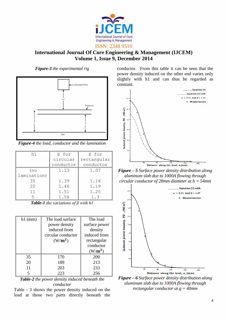
Figure-3 the experimental rig
Figure-4 the load, conductor and the lamination
h1 β for
circular
conductor
β for
rectangular
conductor
(no
lamination)
1.13 1.07
35 1.39 1.16
20 1.46 1.19
11 1.51 1.25
5 1.58 1.3
Table-1 the variations of β with h1
h1 (mm) The load surface
power density
induced from
circular conductor
(W/𝐦𝟐)
The load
surface power
density
induced from
rectangular
conductor
(W/𝐦𝟐)
35 170 200
20 189 213
11 203 233
5 223 256
Table-2 the power density induced beneath the
conductor
Table - 3 shows the power density induced on the
load at those two parts directly beneath the
conductor. From this table it can be seen that the
power density induced on the other end varies only
slightly with h1 and can thus be regarded as
constant.
Figure – 5 Surface power density distribution along
aluminum slab due to 1000A flowing through
circular conductor of 28mm diameter at h = 54mm
Figure – 6 Surface power density distribution along
aluminum slab due to 1000A flowing through
rectangular conductor at g = 40mm

ISSN: 2348 9510
International Journal Of Core Engineering & Management (IJCEM)
Volume 1, Issue 9, December 2014
5
When investigating the effect of the laminations on
the applicability of the superposition method it
proved necessary to measure the voltage
distribution, induced on the load, when 1000A
flowed through the single rectangular conductor,
whichwas above the slab and below the lamination
pack when h1 = 5mm. These readings were
combined with the computer program "W-SC-FIT"
to predict the induced power density from 5 similar
conductors which were parallel to each other and
positioned at 31mm intervals. These 5 conductors
operated under identical conditions to those of the
single conductor with the exception that a current of
600A/conductor and not 1000A was applied. The
results are shown in Figure – 15. The existence of
the laminations did not affect the applicability of the
superposition method. The discrepancy
Figure – 7 Surface power density distribution along
aluminum slab due to 1000A flowing through
circular conductor of 28 mm at h = 54mm with
lamination pack at h1 = 35mm
Figure – 8 Surface power density distribution along
aluminum slab due to 1000A flowing through
rectangular conductor at g = 40mm with lamination
pack at h1 = 35mm
between the measured power density and that
predicted by the superposition method is less than
7%. This small difference is an acceptable
experimental error and proves that this technique can
be used in the relevant applications.
ISSN: 2348 9510
International Journal Of Core Engineering & Management (IJCEM)
Volume 1, Issue 9, December 2014
6
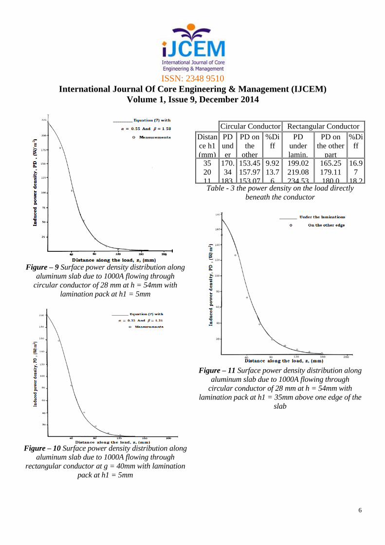
Figure – 9 Surface power density distribution along
aluminum slab due to 1000A flowing through
circular conductor of 28 mm at h = 54mm with
lamination pack at h1 = 5mm
Figure – 10 Surface power density distribution along
aluminum slab due to 1000A flowing through
rectangular conductor at g = 40mm with lamination
pack at h1 = 5mm
Circular Conductor Rectangular Conductor
Distan
ce h1
(mm)
PD
und
er
lami
n.
W/
m2
PD on
the
other
part
W/m2
%Di
ff
PD
under
lamin.
W/m2
PD on
the other
part
W/m2
%Di
ff
35
20
11
5
170.
34
183.
17
202.
87
223.
57
153.45
157.97
153.07
157.21
9.92
13.7
6
24.5
5
29.7
199.02
219.08
234.53
242.93
165.25
179.11
180.0
181.95
16.9
7
18.2
5
23.2
5
25.1
Table - 3 the power density on the load directly
beneath the conductor
Figure – 11 Surface power density distribution along
aluminum slab due to 1000A flowing through
circular conductor of 28 mm at h = 54mm with
lamination pack at h1 = 35mm above one edge of the
slab

ISSN: 2348 9510
International Journal Of Core Engineering & Management (IJCEM)
Volume 1, Issue 9, December 2014
7
Figure – 12 Surface power density distribution along
aluminum slab due to 1000A flowing through
rectangular conductor at g = 40mm with lamination
pack at h1 = 35mm above one edge of the slab
Figure – 13 Surface power density distribution along
aluminum slab due to 1000A flowing through
circular conductor of 28 mm at h = 54mm with
lamination pack at h1 = 5mm above one edge of the
slab
Figure – 14 Surface power density distribution along
aluminum slab due to 1000A flowing through
rectangular conductor at g = 40mm with lamination
pack at h1 = 5mm above one edge of the slab
Figure – 15 Power density distribution along
aluminum slab due to 5 rectangular conductors at

ISSN: 2348 9510
International Journal Of Core Engineering & Management (IJCEM)
Volume 1, Issue 9, December 2014
8
air gap of 40mm,coil pitch of 31mm and current of
600 A/conductor with lamination pack at h1 = 5mm
IV. CONCLUSION
The superposition method can be applied to magnetic
and nonmagnetic loads and to a system containing
laminations. Also, the applicability of this method is
not affected by the current distribution on the
conductor which depends on the position of the
conductor among other conductors. The use of
laminations increases the power density induced on
the load beneath the lamination packs. This power
density is inversely proportional to the distance
between the laminations and the conductor. The
accurate calculation of the power density induced on
a ferromagnetic load requires the variation of the
permeability to be taken into account. Finally, the
work with lamination packs proves that the
superposition method is suitable to applications
involving laminations such as metal melting and
vessel heating. Hence it is conceivable to employ the
superposition method on different applications.
REFERENCES [1] A.K.M.AI-Shaikhli and L. Hobson, “Novel
technique for the design of induction billet
heaters”, IEE PROCEEDINGS, Vol. 133, Pt. B,
No. 5, PP. 323-330, 5 September 1986.
[2] L.Hobson and A.K.M. Al-Shaikhli: “Illustrating
electromagnetics using an industrial process”,
IJEEE, Vol. 23, PP. 77-85, 1986.
[3] A.K.M. Al-Shaikhli and L.Hobson,
“Improvements in the design of induction billet
heaters”, 19th UPEC, University of Dundee,
U.K., April 1984.