effects of head formation and heat treatment on the
TRANSCRIPT
Effects of Head Formation and Heat Treatment on the Mechanical Properties of Connecting
Rod Bolts
A Senior Project
Presented to
The Faculty of Materials Engineering
California Polytechnic State University, San Luis Obispo
In Partial Fulfillment
Of the Requirements for the Degree
Bachelor of Science
By
Matthew Lauretta
Caleb Leavitt
June 11th, 2018
© 2018 Matthew Lauretta, Caleb Leavitt
i
Abstract
Oliver Racing Parts (ORP; Charlevoix, Michigan) is looking to optimize their manufacturing
process for high-strength connecting rod bolts. A high yield strength is desired for the bolts
because deformation would result in catastrophic engine failure. The bolts were made of H11, a
chromium hot-work tool steel; and MLX17, a precipitation hardenable stainless steel. Tensile
testing was performed to determine the tensile and yield strengths of the bolts. Fracture
surfaces were imaged via scanning electron microscopy to characterize the failure modes. To
observe the effects of bolt heading on microstructure and bolt strength, two batches of MLX17
were prepared; one batch being headed then aged (Group A); the other batch being headed,
solution annealed, and then aged (Group B). These bolts were compared to H11 bolts to
determine their viability for use, with the results being in the order of highest to lowest yield
strength: H11 (272 ksi), MLX17 Treatment B (250 ksi), and MLX17 Treatment A (235 ksi). In the
order of highest to lowest tensile strength: H11 (300 ksi), MLX17 Group B (255 ksi), MLX17
Group A (238 ksi). It is suggested that the bolt heading process is causing some overaging in
the MLX17 samples, shown by the increase in strength when strain and aging from the heading
process are undone through heat treatment. H11 bolts were the strongest tested.
Recommendations are to not replace H11 bolts with MLX17 due to a decrease in strength.
Keywords: Materials Engineering, Tensile Test, Automotive Engineering, MLX-17, H11,
Connecting Rod Bolt, PH Stainless Steel, Tool Steel Bolt

ii
Acknowledgements
This work would not have been possible without the support of Oliver Racing Parts, Century
Sun Metal Treating, and Professor Blair London. In addition to sponsoring the project, Joe Moch
and his team and Oliver Racing Parts provided guidance and technical assistance, as well as
manufacturing bolts for testing. Brad Holst and his team at Century Sun Metal Treating assisted
in selecting a heat treatment plan and performing the heat treatment on the bolts. Finally, we
would like to thank Professor Blair London for providing invaluable technical assistance and
advisement.

iii
Table of Contents
Abstract ............................................................................................................................................. i
Acknowledgements .......................................................................................................................... ii
List of Figures.................................................................................................................................. iv
List of Tables ....................................................................................................................................v
1. Introduction ................................................................................................................................. 1
1.1 Oliver Racing Parts (ORP) .................................................................................................... 1
1.2 Problem Statement ............................................................................................................... 1
1.3 The Connecting Rod Bolt ...................................................................................................... 2
1.3.1 Application ...................................................................................................................... 2
1.3.2 Bolt Processing............................................................................................................... 2
1.4 Bolt Testing ........................................................................................................................... 3
1.5 Bolt Alloys .............................................................................................................................. 4
1.5.1 Tool Steel: H11 ............................................................................................................... 4
1.5.2 Precipitation Hardenable Stainless Steel: MLX 17 ........................................................ 6
2. Experimental Design ................................................................................................................... 7
2.1 Heat Treatment ..................................................................................................................... 7
2.2 Tensile Testing ...................................................................................................................... 8
2.3 Safety .................................................................................................................................... 9
2.4 Tensile Strength and Yield Strength ................................................................................... 10
2.4 Microscopy of Fracture Surfaces ........................................................................................ 11
3. Results ...................................................................................................................................... 11
3.1 Tensile Properties ............................................................................................................... 11
3.2 Macro- and Microscopic Views of Fracture Surfaces ......................................................... 15
4. Discussion ................................................................................................................................. 16
4.1 Effect of post-heading solution anneal on strength of MLX17 bolts................................... 16
4.2 Increase in strength of H11 bolts ........................................................................................ 18
4.3 Considering other properties .............................................................................................. 18
4.4 Effect of quenching after bolt heading ................................................................................ 18
4.5 Yield strength calculation for MLX17 .................................................................................. 19
5. Conclusions .............................................................................................................................. 20
References .................................................................................................................................... 21
Appendix ....................................................................................................................................... 22

iv
List of Figures
Figure 1. The connecting rod, which is made up of the “Small End” which connects to the piston
and the “Big End” which connects to the crankshaft. The bearing cap is connected to the rod
with two bolts [2]. ............................................................................................................................ 2
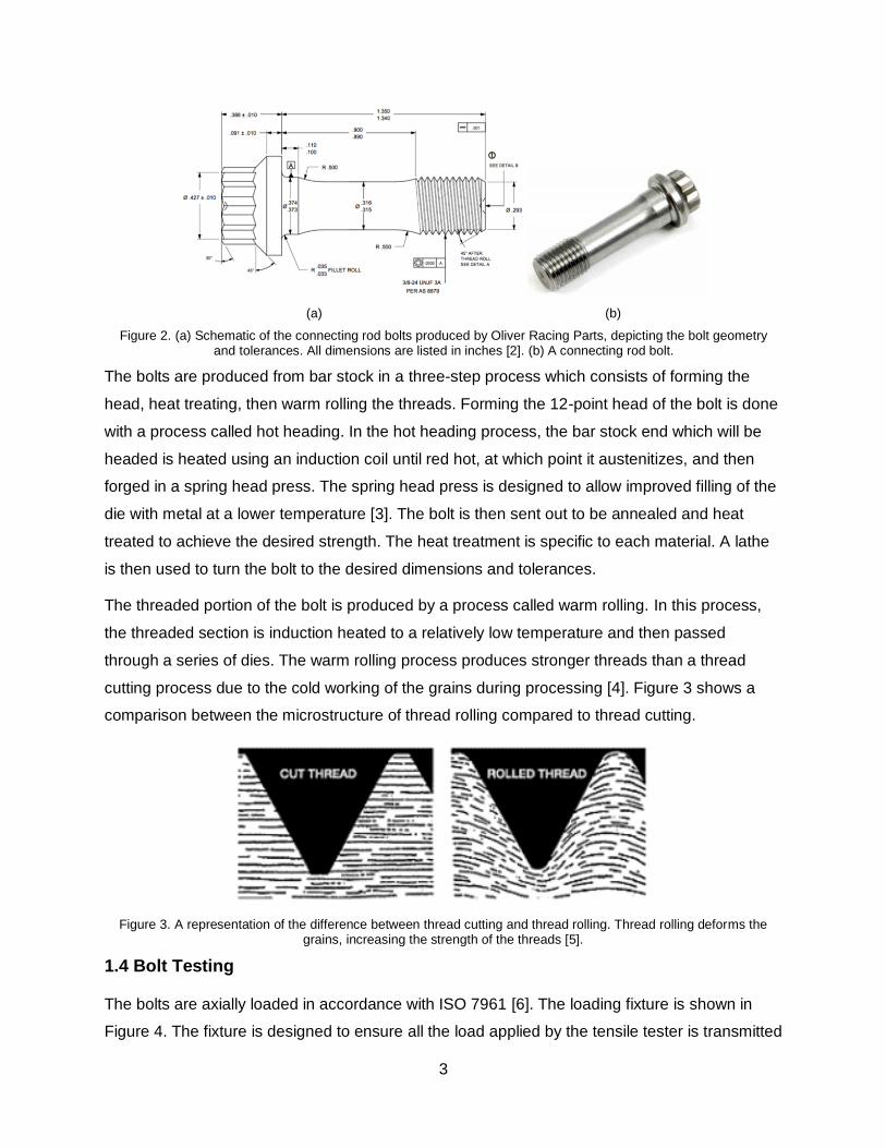
Figure 2. (a) Schematic of the connecting rod bolts produced by Oliver Racing Parts, depicting
the bolt geometry and tolerances. All dimensions are listed in inches [2]. (b) A connecting rod
bolt. .................................................................................................................................................. 3
Figure 3. A representation of the difference between thread cutting and thread rolling. Thread
rolling deforms the grains, increasing the strength of the threads [5]. ........................................... 3
Figure 4. Schematic of the bolt testing fixture, as designed by recommendations from ISO 7961
[6]. ................................................................................................................................................... 4
Figure 5. Tempering temperature vs HRC, showing the influence of austenitizing temperature,
tempering time, and tempering temperature [9]. ............................................................................ 5
Figure 6. Microstructure visible under optical microscopy, showing martensitic matrix [1]. .......... 6
Figure 7. Aging temperature and time, and resulting yield strength for MLX17 stainless steel. A
lower aging temperature held for longer will produce the highest strength possible [1]. .............. 7
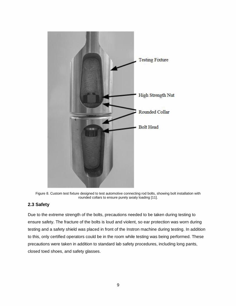
Figure 8. Custom test fixture designed to test automotive connecting rod bolts, showing bolt
installation with rounded collars to ensure purely axialy loading [11]. ........................................... 9
Figure 9. The extension at which the maximum of the 2nd derivative occurs corresponds to the
extension at which the material yields. [2] .................................................................................... 11
Figure 10. Typical raw data output from the Instron software, this graph showing samples 1-10
of H11. Complete results are available in the appendix. ............................................................. 12
Figure 11. Compilation of H11 data. Some noise from settling is still visible in select samples,
however a general trend of yield strength and tensile strength is visible. ................................... 13
Figure 12. Compilation of MLX17 Re Solution Annealed data. The dashed line represents the
estimated yield strength of 250 ksi. .............................................................................................. 13
Figure 13. Compilation of MLX17 As Received data. The dashed line represents the estimated
yield strength of 235 ksi. ............................................................................................................... 14
Figure 14. Macroscopic view of: (a) H11, showing a rough fracture surface with lips at the
outermost edges, and (b) MLX17, showing a prominent cup and cone fracture surface............ 16
Figure 15. SEM imaging of fracture surfaces of (a) H11 and (b) MLX17. Due to being a less
ductile alloy, the H11 had to be viewed at slightly higher magnification to see the same
microvoid coalescence characteristic of a ductile fracture. .......................................................... 16
v
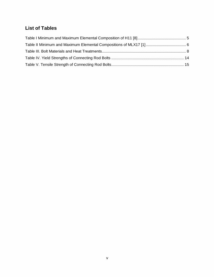
List of Tables
Table I Minimum and Maximum Elemental Composition of H11 [8] .............................................. 5
Table II Minimum and Maximum Elemental Compositions of MLX17 [1] ...................................... 6
Table III. Bolt Materials and Heat Treatments ................................................................................ 8
Table IV. Yield Strengths of Connecting Rod Bolts ..................................................................... 14
Table V. Tensile Strength of Connecting Rod Bolts ..................................................................... 15
1
1. Introduction
1.1 Oliver Racing Parts (ORP)
Oliver Racing Parts (Charlevoix, MI) is a manufacturer of connecting rods for high performance
automotive engines. Their connecting rods boast a high strength to weight ratio, which is
beneficial in a racing engine application where a reduction in rotating mass will increase engine
performance. ORPs connecting rods are sold as a package with bolts produced by Automotive
Racing Products (ARP; Ventura, CA). ORP has developed their own bolt manufacturing
capabilities to eliminate the need to purchase bolts from ARP. ORP needs to characterize and
refine their manufacturing and heat treatment processes to maximize the strength of their bolts,
and investigate the viability of replacement materials which will provide superior performance for
their bolts. Alloys investigated were H11 (the current material) and MLX 17.
1.2 Problem Statement
Bolts made from MLX17 are demonstrably lower in strength than expected, and it is suspected
this is being caused by the heading process during bolt manufacture, though the effects the
process has are uncharacterized. The ideal heat treatment for MLX17 consists of a solution
heat treatment followed by aging, either at 510°C or 540°C [1]. Following this heat treatment
path, with bolt formation occurring after the solution heat treatment, MLX17 samples tested
during the 2016-17 academic year were found to have much lower strength than maximum. The
bolts should display a yield strength of 265 ksi and a tensile strength of 285 ksi, however
previous tests show a yield strength of 215-220 ksi and a tensile strength of 220-230 ksi [2]. To
address this problem, the project consisted of tensile testing reference H11 bolts, and MLX17
bolts of differing heat treatments, as well as performing fracture analysis on a selection of
untested samples. The specific goals of the project are to determine a heat treatment plan to
make MLX17 bolts as strong as existing H11 bolts, and to determine the effect of heading on
bolt microstructures and properties. Testing methods and analysis techniques to accomplish the
project goals were tensile testing H11 bolts and two different sets of MLX17 bolts, each with
various heat treatments, to determine their yield and tensile strength. Representative fracture
surfaces of each alloy were examined under scanning electron microscopy (SEM) to determine
fracture type.

2
1.3 The Connecting Rod Bolt
1.3.1 Application
Connecting rods connect the piston of an internal combustion engine to the crankshaft, and
allow the linear motion of the piston to be translated to rotary motion of the crankshaft. The
connecting rod is connected to the piston on the small end, and the crankshaft by the bearing
cap on the big end of the rod, which is held on with two bolts (Figure 1). The connecting rod is
subject to cyclic loading at up to 18,000 cycles per minute, and extreme tensile forces. Because
of this, the connecting rod bolts must have a high tensile strength and toughness. Toughness is
important because it will prevent crack formation and propagation during the cyclic loading the
bolt will experience during operation.
Figure 1. The connecting rod, which is made up of the “Small End” which connects to the piston and the “Big End” which connects to the crankshaft. The bearing cap is connected to the rod with two bolts [2].
1.3.2 Bolt Processing
The bolts are approximately 1.75" in length and ⅜" in diameter, with ⅜-24 UNJF 3A threads
(Figure 2). The undercut in the center of the bolt is present to prevent bolt failure in the threads.
Failure in the threads would damage the connecting rod upon failure and increase the cost and
work needed to repair a failure.
3
(a) (b)
Figure 2. (a) Schematic of the connecting rod bolts produced by Oliver Racing Parts, depicting the bolt geometry and tolerances. All dimensions are listed in inches [2]. (b) A connecting rod bolt.
The bolts are produced from bar stock in a three-step process which consists of forming the
head, heat treating, then warm rolling the threads. Forming the 12-point head of the bolt is done
with a process called hot heading. In the hot heading process, the bar stock end which will be
headed is heated using an induction coil until red hot, at which point it austenitizes, and then
forged in a spring head press. The spring head press is designed to allow improved filling of the
die with metal at a lower temperature [3]. The bolt is then sent out to be annealed and heat
treated to achieve the desired strength. The heat treatment is specific to each material. A lathe
is then used to turn the bolt to the desired dimensions and tolerances.
The threaded portion of the bolt is produced by a process called warm rolling. In this process,
the threaded section is induction heated to a relatively low temperature and then passed
through a series of dies. The warm rolling process produces stronger threads than a thread
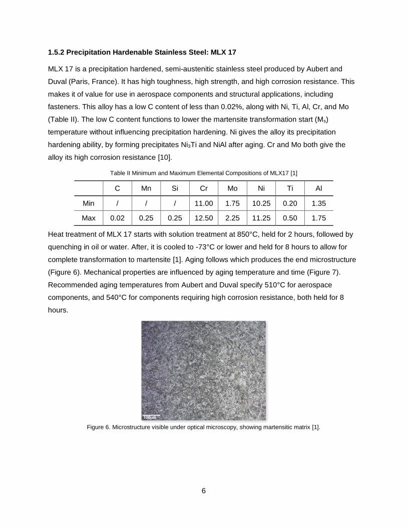
cutting process due to the cold working of the grains during processing [4]. Figure 3 shows a
comparison between the microstructure of thread rolling compared to thread cutting.
Figure 3. A representation of the difference between thread cutting and thread rolling. Thread rolling deforms the grains, increasing the strength of the threads [5].
1.4 Bolt Testing
The bolts are axially loaded in accordance with ISO 7961 [6]. The loading fixture is shown in
Figure 4. The fixture is designed to ensure all the load applied by the tensile tester is transmitted

4
to the bolt and accurate results are recorded. The bolt is secured to the fixture with a nut that
simulates the threaded end of the connecting rod which the bolt would normally be threaded in.
To ensure accurate results and fully test the strength of the bolts, sufficient thread engagement
with the nut is necessary.
Figure 4. Schematic of the bolt testing fixture, as designed by recommendations from ISO 7961 [6].
A constant loading rate of 750 N/min is recommended per mm2 of nominal shank cross
sectional area [6]. The yield strength and ultimate tensile strength is calculated by dividing the
load at which plastic deformation occurs and the maximum load by the minimum diameter of the
bolt. In the case of these bolts, this is the area of the undercut. The ductility of the bolt is
measured by the percent reduction in area (%RA) of the bolt, and is calculated as the percent
difference between the bolt shank’s cross-sectional area before and after failure. This method of
measuring the reduction in area for full sized bolts is adopted from ASTM F606 for machined
test samples [7].
1.5 Bolt Alloys
1.5.1 Tool Steel: H11
H11 is a chromium hot-worked steel, possessing high hardenability and high toughness, making
it desirable for use in tools. The alloy contains 0.33-0.43% C with large amounts of Cr and Mo to
aid in the formation of carbides (Table I). Carbides serve as the primary strengthening
mechanism for H11. Austenitizing is used instead of normalizing to ensure all previous carbides
are dissolved into solid solution. The solubilities of the alloying elements in Fe are dependent on

5
the temperature, so a higher austenitizing temperature results in more alloying elements
available to precipitate out during heat treatment. Any precipitates not dissolved in austenitizing
can be used to prevent excessive grain growth and increase strength.
Table I Minimum and Maximum Elemental Composition of H11 [8]
C Mn P S Si Cr V Mo
Min 0.35 0.20 / / 0.80 4.75 0.30 1.10
Max 0.45 0.60 0.03 0.03 1.25 5.50 0.60 1.60
While it is possible for H11 to achieve full hardness through air cooling, typical quenching
occurs either in a nitrogen gas atmosphere or oil. This is done to prevent embrittlement during
air cooling. After quenching, most of the martensite has formed in the alloy. Retained austenite
is a risk with high dissolved alloying element concentrations, so the austenitizing temperature is
carefully chosen to balance maximizing alloying element concentration in the material and
minimizing retained austenite. Typical austenitizing temperatures range from 995 to 1025°C,
with hold times around 15 to 40 minutes [9]. Tempering follows austenitizing, and transforms
martensite into a ferrite matrix with carbide precipitates known as tempered martensite. Multiple
tempers can be used to reduce the amount of retained austenite. Mechanical properties are
influenced by a combination of tempering temperature and time (Figure 5). Ideal heat treatment
involves austenitizing above 1000°C, with a tempering temperature of 540°C to allow for
flexibility in tempering times depending on processing requirements.
Figure 5. Tempering temperature vs HRC, showing the influence of austenitizing temperature, tempering time, and tempering temperature [9].
6
1.5.2 Precipitation Hardenable Stainless Steel: MLX 17
MLX 17 is a precipitation hardened, semi-austenitic stainless steel produced by Aubert and
Duval (Paris, France). It has high toughness, high strength, and high corrosion resistance. This
makes it of value for use in aerospace components and structural applications, including
fasteners. This alloy has a low C content of less than 0.02%, along with Ni, Ti, Al, Cr, and Mo
(Table II). The low C content functions to lower the martensite transformation start (Ms)
temperature without influencing precipitation hardening. Ni gives the alloy its precipitation
hardening ability, by forming precipitates Ni3Ti and NiAl after aging. Cr and Mo both give the
alloy its high corrosion resistance [10].
Table II Minimum and Maximum Elemental Compositions of MLX17 [1]
C Mn Si Cr Mo Ni Ti Al
Min / / / 11.00 1.75 10.25 0.20 1.35
Max 0.02 0.25 0.25 12.50 2.25 11.25 0.50 1.75
Heat treatment of MLX 17 starts with solution treatment at 850°C, held for 2 hours, followed by
quenching in oil or water. After, it is cooled to -73°C or lower and held for 8 hours to allow for
complete transformation to martensite [1]. Aging follows which produces the end microstructure
(Figure 6). Mechanical properties are influenced by aging temperature and time (Figure 7).
Recommended aging temperatures from Aubert and Duval specify 510°C for aerospace
components, and 540°C for components requiring high corrosion resistance, both held for 8
hours.
Figure 6. Microstructure visible under optical microscopy, showing martensitic matrix [1].

7
Figure 7. Aging temperature and time, and resulting yield strength for MLX17 stainless steel. A lower aging temperature held for longer will produce the highest strength possible [1].
2. Experimental Design
2.1 Heat Treatment
Heat treatments for H11 and MLX17 were chosen based on multiple factors. To maintain
repeatability with prior experiments performed, heat treatments for MLX17 and H11 were
duplicated, along with a new heat treatment for MLX17 (Table I). Due to changes in processing
of the bolt, these duplicate heat treatments are required to ensure compatibility with prior
results, and verify that these changes in processing have not significantly altered the properties
previously observed. A second heat treatment was specified for MLX17 in an attempt to reverse
any possible overaging influence from the heading process. The MLX17 is received by the
manufacturer in the solution annealed condition; this second heat treatment repeats the solution
anneal treatment after the heading process and prior to aging. These two groups are henceforth
referred to as As Received and Re-Solution Annealed, respectively.

8
Table III. Bolt Materials and Heat Treatments
Material Heat Treatment Sample Size
H11
Standard Heat Treatment
1. Austenitize at 1750F 2. Triple Temper at 1000F
20
MLX17
Re-Solution Annealed
1. Heat to 1550F for 2 hours 2. Brine quench 3. Hold at -150F for 8 hours 4. Warm to room
temperature in air
5. Age at 950F for 8 hours
20
As Received
1. Age at 950F for 8 hours 20
2.2 Tensile Testing
Tensile testing was performed on a 150 kN Instron mechanical testing system. All testing was
performed to the ISO 7961 standard, using a custom two-piece fixture to ensure purely axial
loading during testing (Figure 8). The bolt was inserted between the two pieces of the fixture
and a 17-4 PH stainless steel nut was hand-tightened to the bolt to secure it, with ISO 7961
calling for two threads outside of the bolt. The nut was replaced after every five tests, both for
safety and reliability of measurements. To maintain a parallelism between the between the bolt
and the loading axis, rounded collars made of O-1 tool steel heat treated to HRC 53 were
inserted between the fixture and the bolt head and nut. 20 samples of each alloy and heat
treatment were tested, with tests lasting approximately two to four minutes each. Bolts were
tested to fracture, at a crosshead displacement rate of 0.15 inches per minute.
9
Figure 8. Custom test fixture designed to test automotive connecting rod bolts, showing bolt installation with rounded collars to ensure purely axialy loading [11].
2.3 Safety
Due to the extreme strength of the bolts, precautions needed to be taken during testing to
ensure safety. The fracture of the bolts is loud and violent, so ear protection was worn during
testing and a safety shield was placed in front of the Instron machine during testing. In addition
to this, only certified operators could be in the room while testing was being performed. These
precautions were taken in addition to standard lab safety procedures, including long pants,
closed toed shoes, and safety glasses.
10
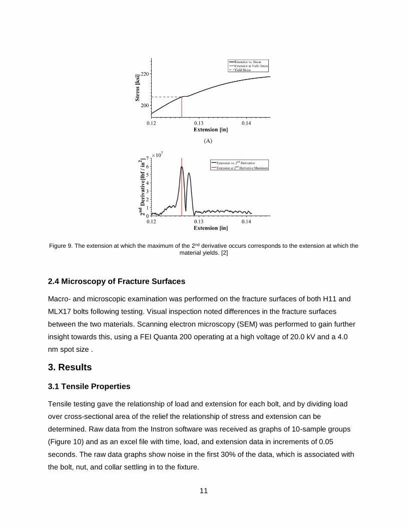
2.4 Tensile Strength and Yield Strength
Tensile strength is defined as the maximum stress a part can withstand before fracture. To
calculate the tensile strength of the bolts, the maximum load was divided by the original cross-
sectional area of the relief section. Yield strength is defined as the maximum stress a part can
withstand before beginning to plastically deform. Since the bolt is a non-conventional geometry
and the fixture does not allow room for an extensometer to be attached, the traditional 0.2%
offset method cannot be used to calculate yield strength. The load associated with the yield
strength was estimated to occur at the greatest change in slope of the load vs. extension plot, or
the maximum of the second derivative of load vs. extension. A first derivative was calculated by
dividing the change in load across the change in displacement. The second derivative was
calculated in a similar manner, instead by dividing the change in the first derivative over the
change in displacement. The data was also clipped to a range of data where the yield strength
was expected. The lower limit of the interval was defined as 30% of all data, to eliminate the
noise associated with the bolt settling in to the fixture at the beginning of the tests. The upper
limit of the interval was defined as 90% of the maximum load, because yielding occurs before
the maximum load is achieved. The yield load could then be determined as the load associated
with the displacement where the second derivative reaches a maximum (Figure 9). Dividing this
yield load by the original cross-sectional area of the relief section.
11
Figure 9. The extension at which the maximum of the 2nd derivative occurs corresponds to the extension at which the material yields. [2]
2.4 Microscopy of Fracture Surfaces
Macro- and microscopic examination was performed on the fracture surfaces of both H11 and
MLX17 bolts following testing. Visual inspection noted differences in the fracture surfaces
between the two materials. Scanning electron microscopy (SEM) was performed to gain further
insight towards this, using a FEI Quanta 200 operating at a high voltage of 20.0 kV and a 4.0
nm spot size .
3. Results
3.1 Tensile Properties
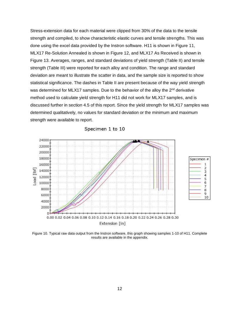
Tensile testing gave the relationship of load and extension for each bolt, and by dividing load
over cross-sectional area of the relief the relationship of stress and extension can be
determined. Raw data from the Instron software was received as graphs of 10-sample groups
(Figure 10) and as an excel file with time, load, and extension data in increments of 0.05
seconds. The raw data graphs show noise in the first 30% of the data, which is associated with
the bolt, nut, and collar settling in to the fixture.
12
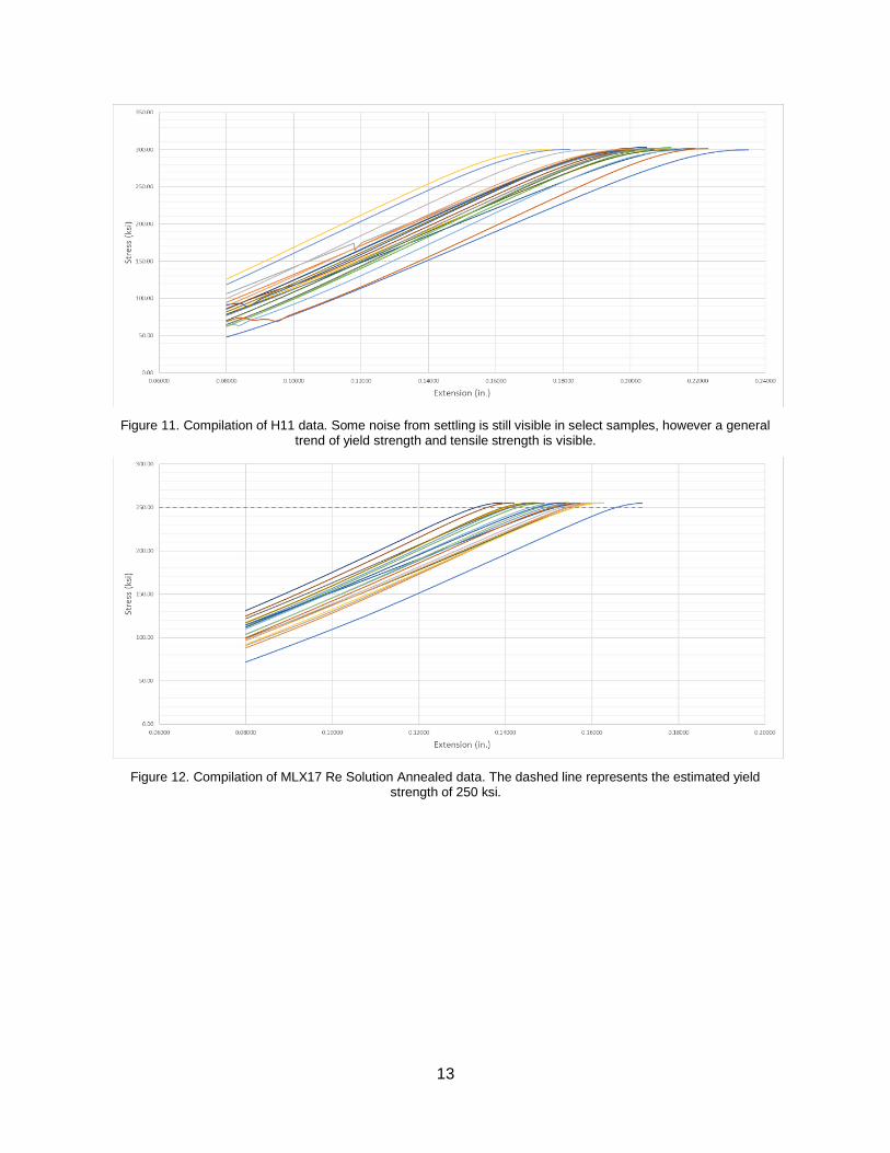
Stress-extension data for each material were clipped from 30% of the data to the tensile
strength and compiled, to show characteristic elastic curves and tensile strengths. This was
done using the excel data provided by the Instron software. H11 is shown in Figure 11,
MLX17 Re-Solution Annealed is shown in Figure 12, and MLX17 As Received is shown in
Figure 13. Averages, ranges, and standard deviations of yield strength (Table II) and tensile
strength (Table III) were reported for each alloy and condition. The range and standard
deviation are meant to illustrate the scatter in data, and the sample size is reported to show
statistical significance. The dashes in Table II are present because of the way yield strength
was determined for MLX17 samples. Due to the behavior of the alloy the 2nd derivative
method used to calculate yield strength for H11 did not work for MLX17 samples, and is
discussed further in section 4.5 of this report. Since the yield strength for MLX17 samples was
determined qualitatively, no values for standard deviation or the minimum and maximum
strength were available to report.
Figure 10. Typical raw data output from the Instron software, this graph showing samples 1-10 of H11. Complete results are available in the appendix.
13
Figure 11. Compilation of H11 data. Some noise from settling is still visible in select samples, however a general trend of yield strength and tensile strength is visible.
Figure 12. Compilation of MLX17 Re Solution Annealed data. The dashed line represents the estimated yield strength of 250 ksi.

14
Figure 13. Compilation of MLX17 As Received data. The dashed line represents the estimated yield strength of 235 ksi.
Figures 13 through 15 show that consistency within each sample group was high, and all
samples within a group had nearly the same elastic modulus, or slope of the elastic region. It is
also significant to note that some settling noise was still present in the H11 data (Figure 11).
While this is less than ideal, any second derivative peaks associated with this noise was
disregarded when performing yield strength calculations. The two samples in Figure 13 which
are shifted to the right are associated with samples where some extra extension was recorded
initially, but had no significant load applied. This could have come from either the fixture shifting
slightly in the Instron jaws during the first test of a group, or with the bolt being loose within the
fixture at the beginning of testing. This should not be taken too seriously, since these samples
still showed the same yield and tensile strength properties despite the additional recorded
elongation.
Table IV. Yield Strengths of Connecting Rod Bolts
Alloy Heat Treatment
Sample Size
Mean Yield Strength
(ksi)
Minimum Strength
(ksi)
Maximum Strength
(ksi)
Standard Deviation
(ksi)
H11 Standard Heat Treatment
20 272 261.4 283.6 5.3
MLX17
Re-Solution Annealed
20 250 - - -
As-Received 20 235 - - -

15
3.2 Macro- and Microscopic Views of Fracture Surfaces
Fracture surfaces after failure were qualitatively assessed using visual and SEM inspection.
Macroscopically, both bolts failed in the undercut as designed (Figure 14). H11 bolts exhibited
almost no necking, forming a rough fracture surface with the only hint of possible ductile fracture
occurring being small shear lips at the outermost edge of the sample. MLX17 bolts exhibited
easily visible necking, forming a cup and cone fracture surface that is typical of a ductile
fracture.
SEM inspection confirmed both H11 and both conditions of MLX17 bolts failed in ductile
fracture. In both samples, microvoid coalescence is visible (Figure 15). For H11 bolts, a higher
magnification was required to see the microvoid coalescence than in MLX17 bolts. There were
no differences between either condition of MLX17 in their fracture surfaces.
Table V. Tensile Strength of Connecting Rod Bolts
Alloy Heat Treatment
Sample Size
Mean Tensile Strength
(ksi)
Minimum Strength
(ksi)
Maximum Strength
(ksi)
Standard Deviation
(ksi)
H11
Standard Heat
Treatment 20 300 298.9 302.8 1.1
MLX17
Re-Solution
Annealed 20 255 254.7 255.7 0.4
As-Received 20 238 235.3 243.4 1.7

16
(a) (b)
Figure 14. Macroscopic view of: (a) H11, showing a rough fracture surface with lips at the outermost edges, and (b) MLX17, showing a prominent cup and cone fracture surface.
(a) (b)
Figure 15. SEM imaging of fracture surfaces of (a) H11 and (b) MLX17. Due to being a less ductile alloy, the H11 had to be viewed at slightly higher magnification to see the same microvoid coalescence characteristic of a ductile
fracture.
4. Discussion
4.1 Effect of post-heading solution anneal on strength of MLX17 bolts
Previous tests had shown MLX17 to have significantly lower strength than anticipated based on
specifications given by the supplier. It was hypothesized that heat input during the bolt heading
process caused overaging to occur, causing the significant decrease in strength. Aging is the
¼” ¼”

17
process of growing precipitates in the material, which is the primary strengthening mechanism in
precipitation hardened stainless steels like MLX17. These precipitates act to impede dislocation
movement through the alloy, by different mechanisms depending on their coherency. Small
precipitates (on the nanometer scale) are coherent with the surrounding lattice, that is their
crystal lattice is oriented and connected with that of the surrounding matrix. However, since
these precipitates are of a different composition than the surrounding, the lattice spacing is
slightly different, putting a strain on the surrounding matrix. This strain field acts to slow
dislocation movement, since the dislocations must re-orient themselves to make it through the
field. As the precipitates grow, they become less coherent until they reach a point of being
incoherent, that is their crystal lattice is no longer aligned with the matrix. When the precipitates
are this size, they impede dislocation movement by forcing dislocations to bow around them.
Precipitates will continue to grow with aging, with the material’s strength growing proportionally.
Once peak strength is achieved, the precipitates continue to grow which causes a decrease in
strength. This decrease in strength is called overaging, and is caused by the precipitates
becoming so few and large, that they no longer effectively impede dislocation motion as they
once did.
Aging is achieved by holding a solution annealed alloy at an elevated temperature for a given
amount of time. The aging process is extremely temperature dependent, a difference of 25
degrees or 30 minutes can raise or lower strength by 10 ksi or more [1]. The bolt heading
process exposes the alloy to temperatures hundreds of degrees above an ideal aging
temperature, which could cause the material to overage during the heading process. When a
typical aging procedure is then carried out, the material could be overaged and have a lower
than expected strength.
To confirm the posed hypothesis of heading causing overaging, two heat treatments for MLX17
were specified. The “As Received” samples would be the same heat treatment as in previous
tests, with aging occurring for 8 hours at 950 °F. The “Re-Solution Annealed” samples would be
subjected to a second solution annealing process matching the one specified by the
manufacturer after heading but before aging. This solution annealing process consists of
holding the sample at 1550 °F for two hours, then quenching in brine, then freezing and holding
at -150 °F for 8 hours, and then warming to room temperature in air. Following this step, the
bolts would then be aged at 950 °F for 8 hours. The purpose of this solution annealing is to
return the bolts to the as-delivered condition before heat treatment occurs, thus theoretically
reversing any aging that would have occurred during the heading process. The “Re-Solution

18
Annealed” bolts showed an average increase of 15 ksi yield strength and 17 ksi tensile strength.
This is a significant and noticeable increase, which confirms the posed hypothesis that aging is
occurring during the bolt heading process.
4.2 Increase in strength of H11 bolts
H11 bolts with the same heat treatment as previous work were tested as a baseline for the
MLX17 bolts. Upon analysis, it was determined that the H11 bolts displayed an increase in yield
strength and tensile strength of 7 ksi and 30 ksi, respectively. The difference between the bolts
is the processing equipment used to process the current bolts versus the previous bolts.
Previously, ORP has purchased a new induction coil and spring head press for bolt
manufacturing. The new induction coil is designed to have tighter tolerances than the old one to
prevent overheating the bolt outside of the area to be headed. The new spring head press is
designed to allow better fill out of the mold during forging at a lower temperature, which should
allow the alloy to be heated less during heading. While it is understood that the high
temperature during heading will cause overaging in the MLX17 samples, it is not fully
understood why the high heat would affect the H11 samples. This is because the H11 heat
treatment consists of a high temperature (1850 °F) austenitizing step followed by a triple temper
at 1000 °F. This austenitizing step should undo any previous processing stresses or similar
experienced by the bolts. This increase in strength could be an area of investigation in future
experiments.
4.3 Considering other properties
Initially, it was thought that there may be some corrosion concerns with the use of H11. Upon
further research and discussion, it was decided that any corrosion concerns should be
disregarded. While in operation, the connecting rod big end and connecting rod bolts are
immersed in an oil bath. This oil bath would prevent significant corrosion from occurring during
the service life of the bolts.
Another concern is the cyclic fatigue strength of the bolts. Connecting rods experience
thousands of rotations per minute, therefore cyclically loading the bolts thousands of times per
minute for hours on end. Fatigue testing is currently underway by ORP to determine the fatigue
strength of H11 and MLX17.
4.4 Effect of quenching after bolt heading
The bolts tested in the experiment were air cooled after the heading process, however a second
set of bolts was received which were water quenched after the heading process. Bolt sets
19
underwent the same heat treatments, but there were less water-quenched samples received
than air cooled (27 vs. 102). To ensure there was no significant difference associated with the
cooling process after heading, 10 water-quenched bolts were tested. These bolts displayed the
same average strengths as the air-cooled samples, so the rest were not tested. This is
expected, since the quick cooling rate should not have a significant influence compared to the
significance of the aging process.
4.5 Yield strength calculation for MLX17
As mentioned previously, a second derivative method was used to calculate the yield strength of
the bolts, since the non-standard geometry and fixture did not allow for use of an extensometer.
While this method was sufficient for calculating the yield strength of H11 samples, problems
arose when attempting to calculate the yield strength of the MLX17 samples. Calculations
returned yield strength values in the range of 140-175 ksi, which a quick reference to Figures 14
and 15 revealed to be erroneous. There was clearly still a large elastic region before any
yielding was visible. To address this, the yield strengths for the MLX17 samples were
qualitatively estimated based on what looked to be a consistent and reasonable yield point.
While this is not ideal, it is important to keep in mind that yield strength is always an informed
estimate, and the tight grouping of the data suggests that there are no outlying values which
would artificially raise or lower the yield strength. Also of important note is the fact that the
estimated yield strengths are significantly lower than that of the benchmark H11, so a qualitative
estimate based on the graphs should be sufficient.
20
5. Conclusions
(1) H11 bolts were the strongest tested, with a yield strength of 272 ksi and a tensile strength of
300 ksi. This is significantly more than the strongest MLX17 samples, which had a yield strength
of 250 ksi and a tensile strength of 255 ksi.
(2) The heading process is causing overaging in the MLX17 bolts, as shown by the lower than
expected strength in both previous tests and the “As Received” samples. To address this, a re-
solution annealing step must be added to the heat treatment of MLX17 bolts to optimize their
strength. An increase of 15 ksi yield strength is significant, and justifies the extra processing
step in a strength-driven application.
(3) Since strength is the primary concern for the connecting rod bolt application, H11 is the best
alloy tested. While there may be some concerns with the corrosion resistance of H11, the
constant immersion in oil prevents any significant corrosion. H11 also has the advantage of
achieving significantly higher strength than MLX17 with less processing time and fewer
processing steps.

21
References
[1] Aubert and Duval. “MLX 17 X1CrNiMoAlTi12-11-2 A Very High Strength Stainless Steel.”
Aubert and Duval, 2017.
[2] Lam, Leland “Tensile Properties of High-Strength Connecting Rod Bolts”. June 2017
http://digitalcommons.calpoly.edu/matesp/163
[3] J. Moch, Interviewee [Interview]. 30 October 2017
[4] Atlanta Rod & Manufacturing. “Advantages of Rolled Threads”. Atlanta Rod & Manufacturing,
2008
[5] Melfast “Rolled vs Cut Thread Bolts” Accessed 13 November 2017
[6] International Organization for Standards. ISO 7961: 1994 Aerospace -- Bolts -- Test
methods. International Organization for Standardization, 1994
[7] ASTM F606-95b Standard test methods for determining the mechanical properties of
externally and internally threaded fasteners, washers, and rivets. American Society for Testing
and Materials, West Conshohocken, PA, 1995
[8] ASTM A681-08(2015) Standard Specification for Tool Steels Alloy, ASTM International, 2015
[9] R.A. Mesquita, R. Schneider and C.S. Gonçalves, Heat Treating of Hot-Work Tool Steels,
Heat Treating of Irons and Steels. Vol 4D, ASM Handbook, ASM International, 2014, p 336–
346.
[10] Li Ling, Heat Treating of Precipitation-Hardenable (PH) Stainless Steel and Iron Base
Superalloys, Heat Treating of Irons and Steels. Vol 4D, ASM Handbook, ASM International,
2014, p 397–417.
[11] McCabe, Megan, Randall, Samuel “Comparison Study of Tensile Strength , Ductility, and
Fracture Mode of H11, ARP 2000, and MP35N Connecting Rod Bolts for Use in High
Performance Racing Engines”. June 2016 http://digitalcommons.calpoly.edu/matesp/143
22
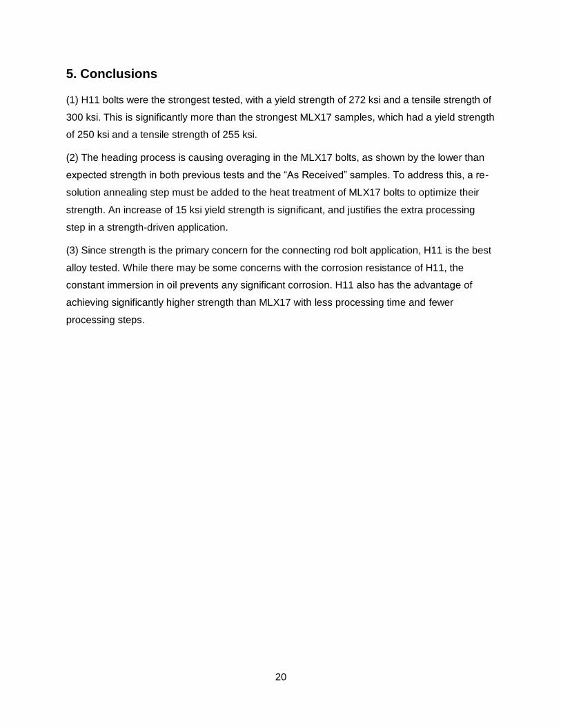
Appendix
23
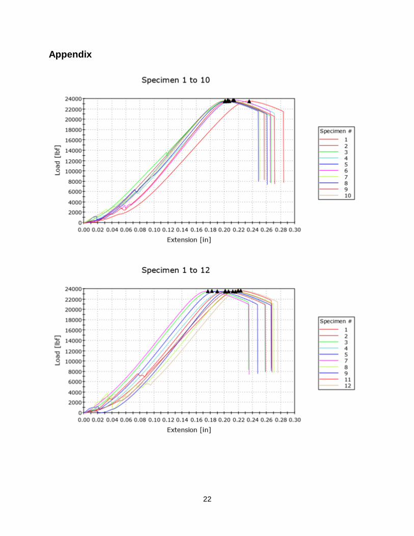
A.1. H11 Raw Data
24
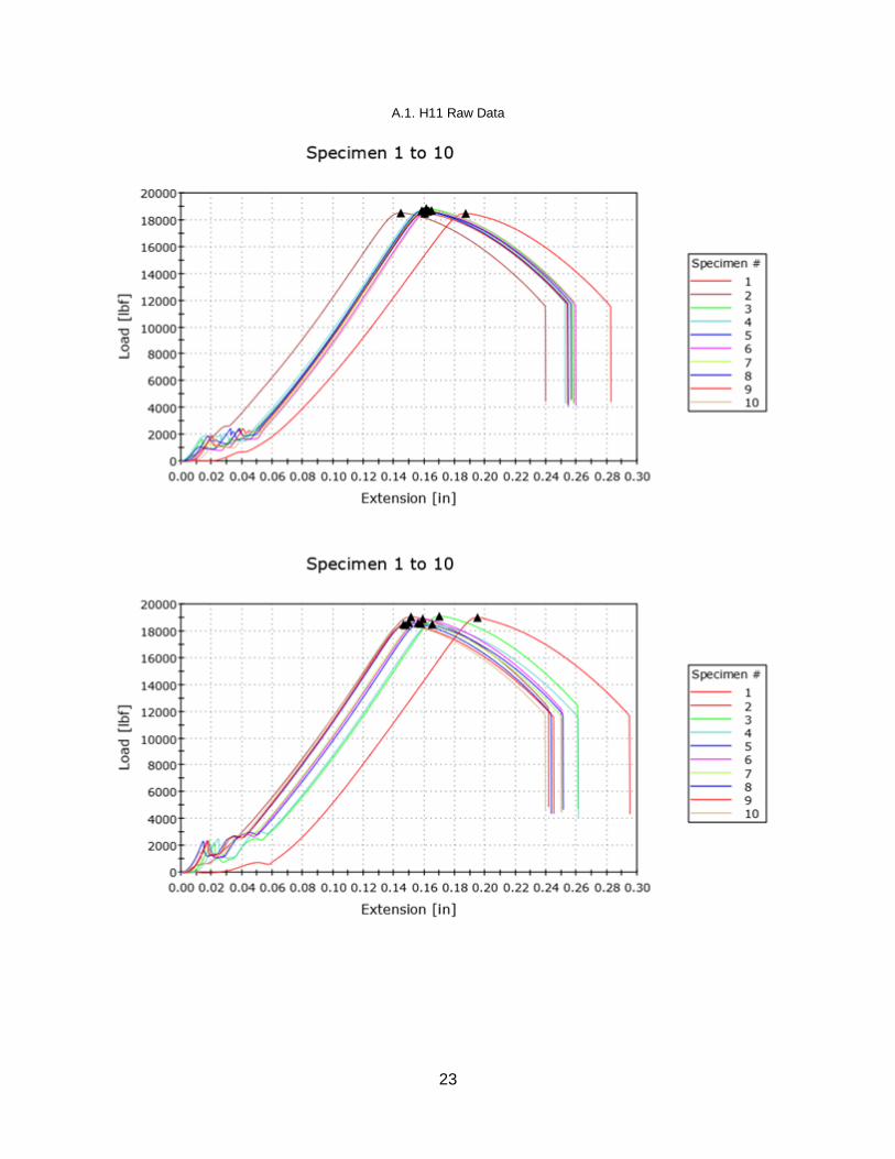
A.2. MLX17 As-Received Raw Data
A.3. MLX17 Re-Solution Annealed Raw Data