effects of geology and geotechnical properties of rocks
TRANSCRIPT

Missouri University of Science and Technology Missouri University of Science and Technology
Scholars' Mine Scholars' Mine
International Conference on Case Histories in Geotechnical Engineering
(1988) - Second International Conference on Case Histories in Geotechnical Engineering
02 Jun 1988, 10:30 am - 3:00 pm
Effects of Geology and Geotechnical Properties of Rocks for the Effects of Geology and Geotechnical Properties of Rocks for the
Selection of Type of Dams Selection of Type of Dams
Baqir Hasan Water & Power Development Authority, Lahore, Pakistan
Follow this and additional works at: https://scholarsmine.mst.edu/icchge
Part of the Geotechnical Engineering Commons
Recommended Citation Recommended Citation Hasan, Baqir, "Effects of Geology and Geotechnical Properties of Rocks for the Selection of Type of Dams" (1988). International Conference on Case Histories in Geotechnical Engineering. 10. https://scholarsmine.mst.edu/icchge/2icchge/2icchge-session2/10
This work is licensed under a Creative Commons Attribution-Noncommercial-No Derivative Works 4.0 License.
This Article - Conference proceedings is brought to you for free and open access by Scholars' Mine. It has been accepted for inclusion in International Conference on Case Histories in Geotechnical Engineering by an authorized administrator of Scholars' Mine. This work is protected by U. S. Copyright Law. Unauthorized use including reproduction for redistribution requires the permission of the copyright holder. For more information, please contact [email protected].

Proceedings: Second International Conference on Case Histories In Geotechnical Engineering, June 1-5, 1988, Sl Louis, Mo., Paper No. 2.44
Effects of Geology and Geotechnical Properties of Rocks for the Selection of Type of Dams Baqir Hasan Chief Geologist, Dams Review Cell, Water & Power Development Authority, WAPDA, Lahore, Pakistan
SYNOPSIS: The topography, geology, foundation conditions and geotechnical properties of the rock units play a dominent role in the selection of type of a dam. It is usually difficult to determine initially, what particular type of dam is technically feasible and economically viable, for a part~ cular dam site. In selecting the most suitable type of dam, a thorough consideration is given to the characteristic of each type of dam. Before the final selection of the type of dam, detailed evaluation is made of location, topography, geology, foundation condition, geological structure, seismicit~odeptb of the overburden in the ·valley section, geotechnical properties of various rock units etc. The paper deals only with the geological problems and geotechnical properties of rock of Kbajuri Kacb and Mangi Dam in Pakistan. It has been demonstrated, as to how far the geology and geotechnical features of rock units have effected the selection of the type of the dam for these two dam sites.
INTRODUCTION
The topography, geology, foundation conditions and geotechnical properties of rock play a dominent role in the selection of type of a dam. The shape and geomorphologic features of the gorge, depth of the bed rock in river valley, structural geological features of the area, not only effect the type of the dam ,but also determine its dimensions. It is usually difficult to determine initially what particular type of dam is technically feasible or most economical for a particular dam site.In selecting the most suitable type of dam, a thorough consideration is given to the characteristic of each type of dam. Evaluation is made of location, topography, geology, foundation conditions~ geological structure, depth of overburden in the valley section, seismicity, .availability of sui table construction materi&;l' geotechnical properties of the rock units, glaciation, hydrological regime of the catchment and constraints by environmental consideratio.n etc. In the selection of dam site, some time the accessibility of the site, spillway discharges, limitation of outlet works and diversion of the river during construction etc. have an important bearing on the type of the dam. The final selection of the type of dam is
generally made after careful considerations of the above factors, which differ from site to site. However, the economics and technical viability of the project, is usually the prime factor in determining and selecting the type of dam.
The geology and geotechnical properties of various rock units of Khajuri Kach and Mangi Dam sites have been described and discussed in this paper briefly,,for location of sites refer Fig. 1. It shall be demonstrated as to how the different geological and geotechnical aspects have effected the selection of type of dam for these two dams.
271
KHA.JURI KACH DAM River Type
Heivht
Capacity
ARABIAN
I. Met! ciGft lit• 2. Kllejuri Kacll 4l.a lite
KHAJURI KACH DAM SITE
MAIIGt DAM River l(•t Heitllt !SS111 Type "-clrfill Ca,acity 0.0435 tJ
FIGURE-I LOCATION MAP
From topographic and morphologic point of view, the proposed Khajuri Kach dam site- on river Gomal is one of the finest in Pakistan refer Fig. 2. The project bas been investigated upto project planning stage. Considerable amount of surface and sub-surface investigations have already been completed which has given quite good insight of the geotechnical properties of the various rock units.
INVESTIGATIONS
Detailed investigations include detailed surface geological mapping, together with sub-surface explorations including drilling, aditting and pitting etc. refer Fig. 3. Moreover the foundation rock; limestone was subjected to the
Second International Conference on Case Histories in Geotechnical Engineering Missouri University of Science and Technology http://ICCHGE1984-2013.mst.edu

detailed grout test, in-situ modulus of elasticity tests and microseismic tests.
Fig. 2-A General view of the main gorge of Khajuri Kach dam site.
GEOLOGIC FEATURES OF THE DAM SITE
The canyon forming the dam site is about 152 m deep, with steep bank slopes on the left side 75° 1/4: 1 and on the right side 65° i: 1 reducing to 45° 1 · : 1 at the top. The gorge near the dam site area has a width of about 30 m at the bottom increasing to about 213 m at the top. The dam site foundations basically consist of thinly bedded Jurassic limestone which is dark grey , hard, and more or less free from caverns-and solution channels refer geologic map Fig. 3 and cross section Fig. 4. The miscroscopic examination indicates that the limestone consists predominantly of calcite (about 95 to 98%'. Other minerals consist of quartz, graphite, biotite, pyrite and gypsum etc. Traces of gypsum occur along the joint planes. The limestone rock unit has some intercalations of argillaceous limestone, marly limestone and shale. The limestone is mostly thin bedded with lot of calcite veins refer Fig. 5.
Outside the gorge, towards west, black sandy shales are exposed, while towards east, greyyellow or reddish .shales are present. The limestone is thin bedded and strike generally in a direction perpendicular to the valley line and dip upstream 30° to 80°. Some deposits of sands and gravels are also met within the gorge along the alignment, but these are superficial and only 2.5 to 4 m deep. The dam foundations substantially protected from seepage by impermeable shale interbeds with an average ground level at about 116 m. These shale intercalations appear to be continuous
272
J ~~·.) SCREE ~ 0 ~ !Om
~.:::J RIVER DEPOSITS f liP STIIICE tr::::::1 LMSTONE SOME SHALE e BOllE HOLE ~ &MARU -m- FAULT = LIMESTONE SOME SHALE
a MAilLS HIGHLY JOINTED =G-2 ADIT ~Y~NESTONE
IEM MODULUS OF ELASTICITY FIG·' SURFACE GEOLOG'(
Llouatone a.r.11o1e
'""' GI!DlDGIC CROSS SECTION
FIGURE.-..
However, the rocks at the dam site have been subjected-to ·considerable tectonic· forces and have suffered extensive jointing and fracturing due to lateral thrusts and overstresses. These rooks also experienced stress release and associated jointing etc. The tectonic forces also produced near the dam site, few · faults of small throw and associated shear surfaces have been noted and evaluated. The traceable faults have been mapped and plotted on the map refer Fig. 3. Among the faults only the 'm' fault, is important. The fault generally dips towards downstream and cuts the dam foundations near the right abutment but this is comparatively a minor fault. Five sets of open joints were produced by the above
Second International Conference on Case Histories in Geotechnical Engineering Missouri University of Science and Technology http://ICCHGE1984-2013.mst.edu
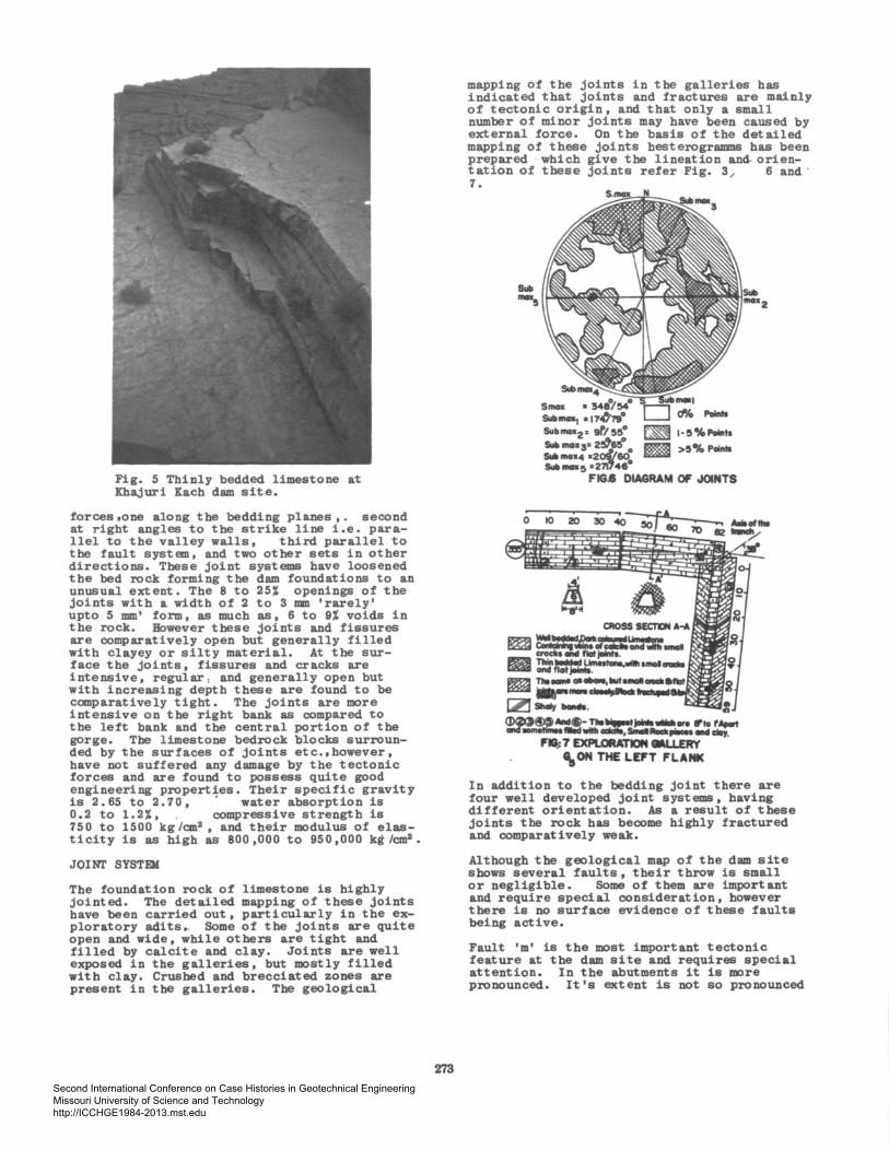
Fig. 5 Thinly bedded limestone at Khajuri Kach dam site.
forces .one along the bedding planes , • second at right angles to the strike line i.e. parallel to the valley walls, third parallel to the fault system, and two other sets in other directions. These joint systems have loosened the bed rock forming the dam foundations to an unusual extent. The 8 to 25% openings of the joints with a width of 2 to 3 mm 'rarely' upto 5 mm' form, as much as, 6 to 9% voids in the rock. BowelVer these joints and fissures are comparatively open but generally filled with clayey or silty material. At the surface the joints, fissures and cracks are intensive, regular , and generally open but with increasing depth these are found to be comparatively tight. The joints are more intensive on the right bank as compared to the left bank and the central portion of the gorge. The limestone bedrock blocks surrounded by the surfaces of joints etc.,however, have not suffered any damage by the tectonic forces and are found to possess quite good engineering properties. Their specific gravity is 2. 65 to 2. 7 0 , · water absorption is 0.2 to 1.2%, . compressive strength is 750 to 1500 kg/cm2 , and their modulus of elasticity is as high as 800 ,000 to 950,000 kg /cm2 •
JOINT SYSTEX
The foundation rock of limestone is highly jointed. The detailed mapping of these joints have been carried out, particularly in the exploratory adits.. Some of the joints are quite open and wide, while others are tight and filled by calcite and clay. Joints are well exposed in the galleries, but mostly filled with clay. Crushed and brecciated zones are present in the galleries. The geological
273
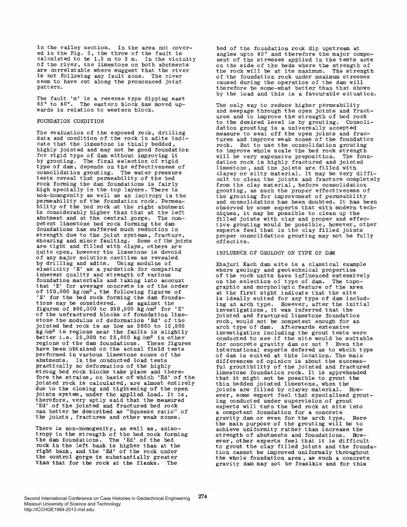
mapping of the joints in the galleries has indicated that joints and fractures are mainly of tectonic origin, and that only a small number of minor joints may have been caused by external force. On the basis of the detailed mapping of these joints besterogramns has been prepared · which give the lineation and- orien-tation of these joints refer Fig. 3 6 and · 7. /
Srnox s..-.. SubmGIIz= gf/55° So.- moxac z51'&5° 0
s..-•4 azol/60 s..-5 =2Ta,46°
Poiftll
~ l-5%,.ta
1!111 >5°.4 Polftls
FIG.8 DIAGRAM 0/f .JOINTS
0 10 20
In addition to the bedding joint there are four well developed joint systems, having different orientation. As a result of these joints the rock has become highly fractured and comparatively weak.
Although the geological map of the dam site shows several faults, their throw is small or negligible. Some of them are important and require special consideration, however there is no surface evidence of these faults being active.
Fault 'm' is the most important tectonic feature at the dam site and requires special attention. In the abutments it is more pronounced. It's extent is not so pronounced
Second International Conference on Case Histories in Geotechnical Engineering Missouri University of Science and Technology http://ICCHGE1984-2013.mst.edu
in the valley section. In the area not covered in the Fig. 3, the throw of the fault is calculated to be 1.5 m to 3 m. In the vicinity of the river, the limestone on both abutments are correlatable where suggest that the river is not following any fault zone. The river seem to have cut along the pronounced joint pattern.
The fault 'm' is a reverse type dipping east 65° to 80°. The eastern block has moved upwards in relation to western block.
FOUNDATION CONDITION
The evaluation of the exposed rock, drilling data and condition of the rock in adits indicate that the limestone is thinly bedded, highly jointed and may not be good foundation for rigid type of dam without improving it by grouting. The final selection of rigid type of dam, depends on the effectiveness of consolidation grouting. The water pressure tests reveal that permeability of the bed rock forming the dam foundations is fairly high specially in the top layers. There is non-homogenity as well as an isotropy in the permeability of the foundation rock. Permeability of the bed rock .at the right abutment is considerably higher than that at the left abutment and at the central gorge. The competent limestone bed rock forming the dam foundations has suffered much reduction in strength due to the joint systems, fracture, shearing and minor faulting. Some of·the joi:ats are tight and filled with clays, others are quite open, however the limestone is devoid of any major solution cavities as revealed by drilling and adits. Using modulus of elasticity 'E' as a yardstick for comparing inherent quality and strength of various foundation materials and taking into account that 'E' for average concrete is of the order of 150,000 kg/cm2 , the following figures of 'E' for the bed rock forming the dam founda-tions may be considered. As against the figures of 800,000 to 950,000 kg/cm2 for 'E' of the unfractured blocks of foundation limestone the modulus of deformation 'Ed' of the jointed bed rock is as low as 2000 to 10 ,000 kg/cm2 in regions near the faults is slightly better i.e. 20,000 to 25,000 kg/cm2 in other regions of the dam foundations. These figures have been obtained on the actual field tests performed in various limestone zones of the abutments. In the conducted load tests practically no deformation of the highly strong be.d rock blocks take place and therefore the strains, on basis of which 'Ed' of the jointed rock is calculated, are almost entirely due to the closing and tightening of the open joints system, under the applied load. It is, therefore, very aptly said that the measured 'Ed' of the jointed and fractured bed rock can better be described as "Squeeze ratio" of the joi.nt~, fractures and other weak zones.
There is non-homogenity, as well as, anisotropy in the strength of the bed rock forming the dam foundations. The 'Ed' of the bed rock in the left bank i.s higher than at the right bank, and the 'Ed' of the rock under the control gorge is substantially greater than that for the rock at the flanks. The
274
bed of the foundation rock dip upstream at angles upto 80° and therefore the major component of the stresses applied in the tests acts on the side of the beds where the strength of the rock will be at its maximum. The strength of the foundation rock under maximum stresses caused during the operation of the dam will therefore be some-what better than that shown by the load and this is a favourable situation.
The only way to reduce higher permeability and seepage through the open joints and fractures and to improve the strength of bed rock to the desired level is by grouting. Consolidation grouting is a universally accepted measure to seal off the open joints and fractures and improve weak zones of the foundation rock. But to use the consolidation grouting to improve whole scale the bed rock strength will be very expensive preposition. The foundation rock is highly fractured and jointed limestone, and the joints are filled with clayey or silty material. It may be very difficult to clean the joints and fracture completely from the clay material, before consolidation grouting, as such the proper effectiveness of the grouting for improvement of permeability and consolidation has been doubted. It has been observed by some experts that with modern techniques, it may be possible to clean up the filled joints with clay and proper and effective grouting would be possible, however, other experts feel that in the clay filled joints proper consolidation grouting may not be fully effective.
INFLUENCE OF GEOLOGY ON TYPE OF D.IM
Khajuri Kach dam site is a classical example where geology and geotechnical properties of the rock units have influenced extensively on the selection of type of dam. The topographic and morphologic feature of the area at the first sight indicate that the site is ideally suited for any type of dam including an arch type. However, after the initial investigations, it was inferred that the jointed and fractured limestone foundation rock , would not be competent enough for an arch type of dam. Afterwards extensive investigation including the grout tests were conducted to see if the site would be suitable for concrete gravity dam or not ? Even the international experts defered as to whcih type of dam is suited at this location. The main differences of opinion is about the successful groutibility of the jointed and fractured limestone foundation rock. It is apprehended that it might not be possible to grout the thin bedded jointed limestone, when the joints are filled by clayey material. However, some expert feel that specialised grouting conducted under supervision of grout experts will turn the bed rock at site into a competent foundation for a concrete gravity dam or even for the arch type. Here the main purpose of the grouting will be to achieve uniformity rather than increase the strength of abutments and foundations. However, other experts feel that it is difficult to grout the clay filled joints and the foundation cannot be improved uniformaly throughout the whole foundation area, as such a concrete gravity dam may not be feasible and for this
Second International Conference on Case Histories in Geotechnical Engineering Missouri University of Science and Technology http://ICCHGE1984-2013.mst.edu

reason they proposed a rock fill dam. Due to topographic features, spillway for a fill type of dam, at this location would be very expensive. The controversy is still going on. More comprehensive investigations, grouting tests and insitue rock mechanic tests may finally settle the issue.
MANGI DAM PROJECT
The Mangi Dam site, is located about 100 km north east of Quetta on the Khost river. This proposed dam site has been investigated in detail for the drinking water supply of the major town of Quetta by lifting the water for more .than 122 m in 3 stages.
In confirmity with the modern engineering practice in the dam construction, appropriate attention was given to the appreciation and understanding of the geology of Mangi dam · project. For the effective understanding of the geological aspects and influence thereof on the engineering requirement assumption, investigation plans were formulated and ~xecuted. For the accomplishment of the imrestigation objectives, standard techniques and .. tools were deployed which includes surface geological mapping on regional and local basis and sub-surface exploration-drilling of 31 boreholes to a total 1372 m and excavation of pits, to a total length of 7 6 m digging out trenches and adi ts , geophysical studies were also undertaken, for resolving one of the complex seepage and groundwater problems, recently developed techniques such as radio isotope studies were also carried out and experimented. The radio isotope studies were conducted mostly to evaluate the groundwater conditions, particularly its directional movement and its possible effect.
REGIONAL GEOLOGY
The predominant rock units exposed in the immediate project area are limestone and shales. Sandstone and shale are exposed mostly towards west which extend beyond the limits of regional map.
The most striking aspects of the structure are the alternating, well developed anticlines and synclines , which are oriented in eastwest direction. Limbs of both of the anticlines are formed by Brewery limestone, while the synclin·al basin is comprised of Ghazij shale. The southern anticline\ on which the dam site is located plunges towards the west refer Fig. 8.
There are a number of major and minor faults many of regional distributions, which can be traced for long distances. At places major faults have clearly shifted the axes of the anticlines. Several regional faults are traceable on both anticlines and, therefore probably cross the synclinal basin also.
The limestone is jointed, fractured and sheared to varying degree. Apparently the regional structure has influenced the northsouth orientation of many narrow gorges which appear to have been developed along prominent north-south joint pattern.
275
SECTION RUNS ALONG NAL.A
l§ii2iiii) Ghatlj Shale l1iZbiD er-y L.lmes!cne §li2l;il Sllolo L.lmeiiOM (f'arh gooup)
lQiZi;!J Chilton 1.1.....,_ ''•,, Foult FIG.8 REGIONAL GEOLOGY
Many perennial springs have been observed in the Brewery limestone of the northern anticline. They are particularly prominent in the Khum Tangi refer Fig. 8.
A number of perennial springs also exist in the Brewery limestone of the southern anticline downstream of the dam axis refer Fig. 9. The evaluation of regional geology and the investigations to date, suggest that these springs are being generally fed from regional ground water which follows the regional geological structures.
The regional ground water movements in the area are extremely complex. The stream flow entering the Khum nala in the upstream anticline, supplemented by spring flows from within the gorge, often disappears entirely into the alluvium in the gorge. This phenomenon occurs as the water passes the downstream dipping limb of the anticline. All the evidences available indicate that at least some of this water seeps into the Brewery and Chiltan limestones and possiblW passes beneath the reservoir under the syncline. A portion of it emerges in the form of spring downstream of the dam site. This may indicate the possibility of a sizeable groundwater potential existing within the Mangi basin. A programme using radio isotopes as tracer element was utilized to determine the direction of the movement of groundwater. Radio isotope injection in bore holes indicated that the ground water at the abutment is connected with the springs at the abutments.
Second International Conference on Case Histories in Geotechnical Engineering Missouri University of Science and Technology http://ICCHGE1984-2013.mst.edu

Fig. 9 showing location of spring in the Brewery limestone.
DAM SITE GEDLOGY
The dam site is located on the northern limb of the downstream anticline on the Khost river. For a masonry dal!l,the axis would be located about 122 m downstream of the confluence of three tributaries refer Fig. 10. At this axis the width of the gorge at river level
·is only about 25 m with vertical side walls and many over hangs. For a fill type of dam, the axis would be shifted further upstream on to the dip slopes of the anticline.
Fig. 10 General view of the gorge of Mangi dam site.
276
The rock exposed at both the masonry or fill dam sites is Brewery limestone. It is hard, massive to thin bedded, with shale intercalation at lower elevations. At the axis of the masonry dam the limestone can be divided into two units; upper massive limestone and lower highly jointed limestone, with thin intercalations of shale. At the axis for the fill dam, only the massive limestone is exposed on a dip slope refer Fig. 11.
I
·{L MIAN QASAM MANDA
1001'11 I
The bore hole Nos. MRS-13, 18 & 21 including twenty four pits near the upstream toe of the limestone slope have revealed that shale is exposed at a shallow depth, which varies from 0.9 to 4.5 m. The shale is generally soft and splintery at surface but hard at greater depths and obviously impermeable.
The geologic structure at the dam site is not complicated. The limestone dip uniformally
~~¥le~0a~~ ifi-i~gr~Hs'Xisip~r~xi~~f~~spara-llel to the axis of the dam. There appears to be no offset between the abutments, which suggests that there is no apparent fault in the valley section of the gorge. However, a gravity type fault crosses the two abutments in a nearly east-west direction about 41 m upstream of the masonry dam axis. A fault with apparently a small displacement can also be traced across the left abutment near the railway tunnel. There are a number of additional faults further downstream of the axis along which some of the downstream springs emerge.
The limestone is highly jointed with the most prominent joints striking 'a' N 85 Wand dipping 60° to 70° south west and 'b' N 50 W with a dip of 75°- 85° towards south west. These joints are generally spaced about ·0.6 to 1.2 m apart. Two less prominent sets have the following strikes and dips.
1. N 40 W, 45°SW
2 • N 45 E , 77 °SE
Second International Conference on Case Histories in Geotechnical Engineering Missouri University of Science and Technology http://ICCHGE1984-2013.mst.edu

All sets of joints are exposed on the abutment slopes and have been shown on figure 7. The prominent joint sets near the dam axis are quite open and will play an important role in the stability of the slopes and seepage loss through the abutment.
The valley in the gorge is filled by alluvium, composed of silt, sand, gravel and big boulders. The narrowness of the gorge and the steepness of the stream gradient, gives the impression that the gorge may have been formed along a fault Plane, but the detailed study of the st-ratigraphy and -correlatable beds on the two abutments does not support this theory and suggest that the gorge has probably developed along a major joint pattern refer figure 12 and 13. Nine boreholes drilled in the valley section of the gorge 'three on the masonry dam axis' indicate the bed rock to be within 7. 6 m of the surface and thus eliminate the possibility of the existance of buried channel within the valley.
FOUNDATION EVALUATION AND GEOTECHNICAL PROPERTIES
The information obtained from sub-surface exploration indicates that the condition of the limestone improve with depth. However, the rock at depth is moderately to highly jointed. Some of the joints are quite open. This condition contributes to the -appreciable water loss during pressure testing and shows that the limestone is quite permeable. The maximum water loss recorded on the right abutment is 53. 68 lit res /metre/minute at 689 kilo pascals. On the left abutment the maximum water loss is 52.19 litres .metre I minute at 689 kilo pascals. The water losses vary from palce to place, depending upon the intensity and openness of the joints. The valley section bore hole data indicates com-paratively less water loss. This may be due to the presence of thin shale layer in the limestone.
120
~ LimestCM Willi Shale lnterelallon.
~BIB Overburden.
I 11111:1 B«e Hole.
FJG.I2 GEOLOGICAL SECTION
277
r-1625
1600
1575
A
1675
16 1650
1625
1600
1575
~ALLUVIUM.
~ SCREE DEPOSITS.
fiJI GHAZIJ SHALE.
f PROBABLE GEOLOGICAL -"" CONTACT.
j:C:;::r::;J BREWERY LIMESTONE tJ::::::d (MASIVEl.
....-"'FAULT .:s;:P JOINTS
15'51 BAEWERY LIMESTONE HIGIU JOINTED l52:i WITH SHALE INTERCLATIONS.
fi'IG.I3 GEOLOGICAL SECTIONS
In-situ or laboratory tests have not yet been performed .. to det.exm:i.ne t-he. beari-n§ capacity of the limes:tone. However t·he good c:Ore recovery and freshness of the core suggests that the limestone would be quite competent to support either a masonry, or a conooete gravity structure or a fill type of structure of the proposed height. Elaborate bearing pressure tests are, therefore, not essentially required. Due to topography as well as highly jointed nature of the rock, an arch dam is not feasible; enough rock mass is not available behind the left abutment to withstand the thrust from the arch section.
The dam site and reservoir area is punctuated by number of minor and major faults. There is no evidence that these faults are active. However • since this area lies in active seismic zone, the effect of the severe earthquake would probably be concentrated along these comparatively weak planes. It is, therefore, necessary that while designing the dam and appurtenant structures, due consideration factor should be given for adequate seismic factor.
SEEPAGE LOSS
This being a predominantly limestone area, water loss through seepage merits very careful consideration. Appreciable water loss in the borehole during pressure tests, highly jointed nature of the limestone and existance of numer~ ous springs in both the anticlines strongly underline the highly permeable nature of the limestones.
Ground water elevation in the bore holes on the abutments and in the valley has been regu-larly observed. The record indicates that the ground elevation ranges between 1564 and 1567 m. The ground water elevation is influenced by
Second International Conference on Case Histories in Geotechnical Engineering Missouri University of Science and Technology http://ICCHGE1984-2013.mst.edu

the climatic conditions in the region and the ground water table slopes from upstream of the dam axis. Even during the fluctuations the ground water table has maintained the downward slope. The groundwater which lies within the limestone is recharged from the regional groundwater and is not directly connected with the stream flow in the Mangi Basin overlain with thick shale mass.
After the dam is built, a large column of water would be standing against the highly permeable limestone of the anticline. This could contribute significant amount of water to the water table below, which may increase the flow of existing springs and or create new ones downstream of the dam. If such a condition occurs a substantial quantity of water may be lost. The dam site anticline plunges towards the west and may direct the seepage flow in that direction away from the reservoir. This water may be irrecoverably lost.
The most potential seepage area is on the left abutment. The distance between the full reservoir level and the scarp face downstream is only about 41 m. This distance is inadequate. Seepage water , .. almo&t·•uind:er. "full reservoir head, would exert pressure, and could, besides seepage loss, create s-erious stability problem, for highly jointed limestone ledge. The critical area extends to a distance of about 183 m from the left gorge wall. Special drainage and protective measures shall have to be taken in this area.
The expected excessive seepage through the limestone abutments, the valley section and the limestone periphery will require extensive protective measures. The seepage can be reduced to accept able levels, by a well planned grouting programme or blanketing of the slqpes with impervious materials.
The total length of the limestone, which will be in contact with reservoir water will be about 2591 m. In case, a masonry dam is constructed, grouting of the whole limestone periphery would be prohibitively costly. However, it may be possible, to grout the foundatio.ns of the structure only to the extent of 61 to 91 m, on the right abutment and about 183 m on theleft. The remainder of the limestone periphery could be blanketted with impervious material. It may, however, be essential to excavate drainage galleries at several elevations in both the abutments.
In case of fill ;dam it is possible to remedy the seepage problem, by blanketing the entire limestone abutments and periphery by impervious material. The impervious core of the dam could be tied into the reservoir shale , which is at shallow depth and covers the · entire reservoir floor. This will provide more or less a continuous impervious cut-off and will m~nimize the seepage problem. The extensive costly grouting would be considerably reduced or possibly entirely eliminated. Drainage galleries at proper elevations will probably be required for a fill dam also.
278
INFLUENCE OF GEOLOGY AND GEOTECHNICAL PROPERTIES OF ROCK :FOR THE SELECTION OF TYPE OF DAM.
Narrowness of the gorge obviously competent looking exposed rock suggests an arch type of dam. However, the detailed investigation revealed the highly jointed nature of the limestone foundation rock, coupled with the fact that due to. the falling away of a part of the left abutment downstream of the dam axil:! , enough rock mass is not available to withstand the thrust for the arch section makes such a dam unfeasible.
Alternatively the topography and the foundation conditions evidently suggest a masonry or concrete gravity structure and that is what it was initially proposed. However, investigati.on revealed acute seepage problem both due to the regional and local geological aspects. Mangi Dam site is one of the rare project, where regional geological aspect has contributed substantially in the seepage problem at and near the dam site. The regional and local excessive seepage and danger of more excessive seepage after the construction of the dam has effected considerably on the selection of the type of dam. The remedial measures against excessive seepage concrete or masonry dam a very costly prepositon.
For this project, which faces acute water deficiency, seepage control is the most important aspect. In case of rigid structure both extensive and costly grouting and blanketing all along the limestone ridge would not only be extremely costly, but the tie in of the blanket , will be artificial unless and unti11 it is tied with due comparatively impervious shale of the reservoir basin,. In case of fill dam, the impervious shale covering the reservoir thus providing a better seepage control. Since enough rock is available at and near the dam site, rock fill section will be comparativeiy cheaper and earthfil structure. A rockfill dam would, however, require a separate and bigger ·spillway whereas a masonry dam itself would function as such. Addition of a spillway would, therefore, add to the cost of the fill structure. The peripheral blanketing would be common to the both. For fill structure most of the excavated material from the spillway, the diversion and the site preparation could be used in the body of the dam.
In ultimate analysis, it would be the economics which would decide the issue. From the geological and seismic point of view and in the light of the information now available, a fill type of structure is preferable.
Second International Conference on Case Histories in Geotechnical Engineering Missouri University of Science and Technology http://ICCHGE1984-2013.mst.edu