effects of elastic shakedown and bulk … bedrossian - petrofac...1 arek bedrossian jens...
TRANSCRIPT
1
Arek Bedrossian
Jens Fernández-Vega
1st February 2017
EFFECTS OF ELASTIC SHAKEDOWN AND BULK CORROSION THINNING AT A LATERAL BUCKLE
Subsea Expo 2017 1 – 3 February 2017
2
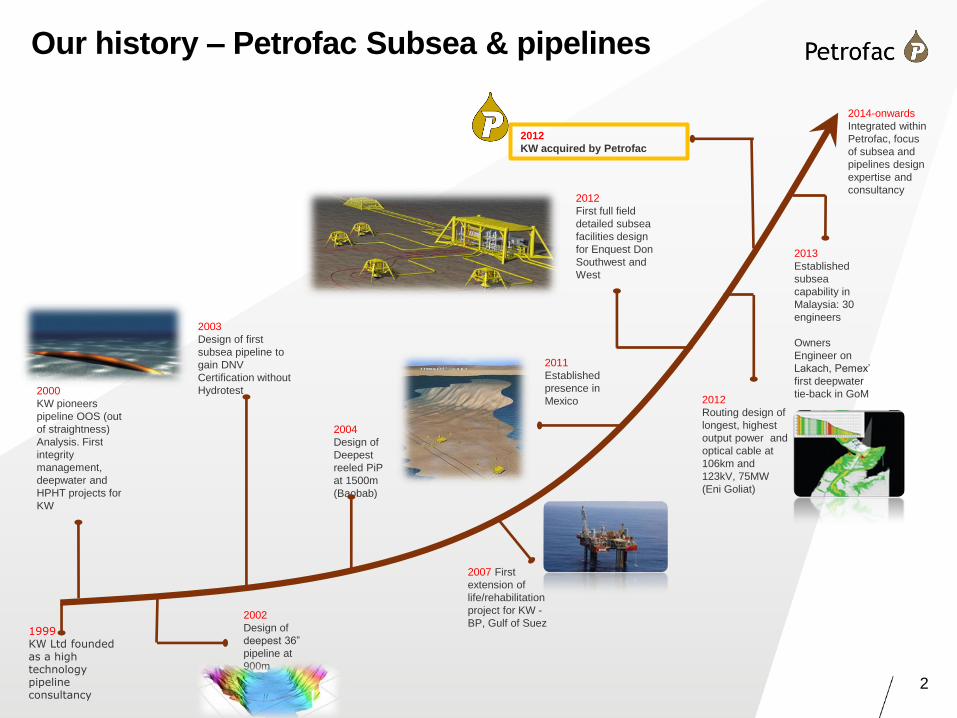
Our history – Petrofac Subsea & pipelines
2012
Routing design of
longest, highest
output power and
optical cable at
106km and
123kV, 75MW
(Eni Goliat)
2004
Design of
Deepest
reeled PiP
at 1500m
(Baobab)
2002
Design of
deepest 36”
pipeline at
900m
2003
Design of first
subsea pipeline to
gain DNV
Certification without
Hydrotest
2013
Established
subsea
capability in
Malaysia: 30
engineers
Owners
Engineer on
Lakach, Pemex’
first deepwater
tie-back in GoM
2000
KW pioneers
pipeline OOS (out
of straightness)
Analysis. First
integrity
management,
deepwater and
HPHT projects for
KW
2012
First full field
detailed subsea
facilities design
for Enquest Don
Southwest and
West
2014-onwards
Integrated within
Petrofac, focus
of subsea and
pipelines design
expertise and
consultancy
2007 First
extension of
life/rehabilitation
project for KW -
BP, Gulf of Suez
2012
KW acquired by Petrofac
2011
Established
presence in
Mexico
1999 KW Ltd founded as a high technology pipeline consultancy
3
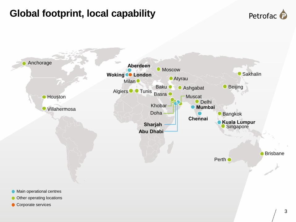
Global footprint, local capability
Main operational centres
Other operating locations
Corporate services
Sakhalin London
Aberdeen
Mumbai
Baku Milan
Khobar
Doha
Houston
Villahermosa
Woking Moscow
Algiers
Abu Dhabi
Sharjah
Basra Tunis
Atyrau
Beijing Ashgabat
Muscat
Chennai
Delhi
Bangkok
Brisbane
Singapore Kuala Lumpur
Perth
Anchorage
4
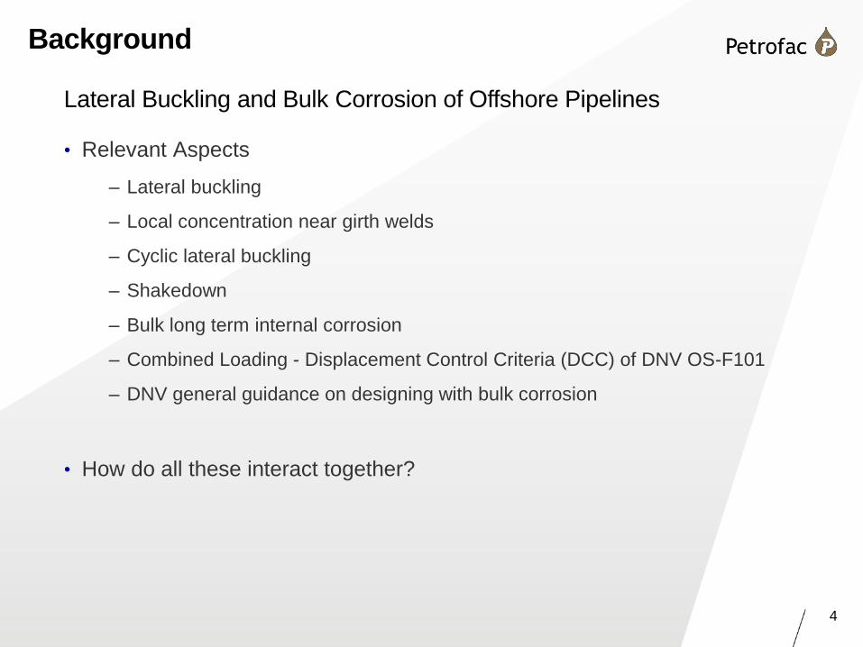
Background
Lateral Buckling and Bulk Corrosion of Offshore Pipelines
• Relevant Aspects
– Lateral buckling
– Local concentration near girth welds
– Cyclic lateral buckling
– Shakedown
– Bulk long term internal corrosion
– Combined Loading - Displacement Control Criteria (DCC) of DNV OS-F101
– DNV general guidance on designing with bulk corrosion
• How do all these interact together?
5
Aim and Scope of Work
Visualise/understand the effects for a typical case
• Objective of work
– Examine the behaviour of pipelines and strain concentrations under repeated lateral
buckling and gradual corrosion thinning of the pipe wall
• Assumptions and scope
– A typical deep water offshore pipeline – not a parametric study
– Uniform corrosion along the pipeline and around the inner bore
– Natural on-bottom lateral buckling; effect of soil berms considered
– Local strain concentration within DNV guidelines
– Operating conditions of pipeline (temperature and pressure) do not change over
design life
6
Geometry, Conditions & Material
• Pipeline Geometry & Material
– Length: 1500m (VAS model, fixed at both ends)
– OD: 323.85mm (12.75”)
– Wall thickness: 15.9mm
• Operation
– Allowed Corrosion: 3.0mm
– Allowed Ovalisation by construction: 2.5%
– Water Depth 1200m
– Internal Pressure: 130 bar
– Temperature: 95˚C (constant along the length)
• Materials
– Pipeline: Material Steel X65 Linear elastic, perfectly plastic
– Weld: 20% Steel Overmatch
7
FE Model
• Abaqus 6.14
• Elastic-plastic, large deformation and frictional contact; static equilibrium
• Hybrid between PIPE31 pipe & C3D8 3-D solid continuum elements
• C3D8 elements embedded in PIPE31 elements
• Beam section is 1496m long. The central solids section is 4m long
• Solid section made of: 3 un-corroded + 1 or 2 layers that could be ‘corroded away’
• Solid to Beam model interface is seamless: Ovalisation of the solids is allowed
• FE model capable of simulating inner corrosion over whole length by incrementally
shaving off layers of solids and replacing beam elements by thinner beam elements
• Axial and lateral pipe-soil frictional resistance applied to both beam & solids sections
FE Model Description
8
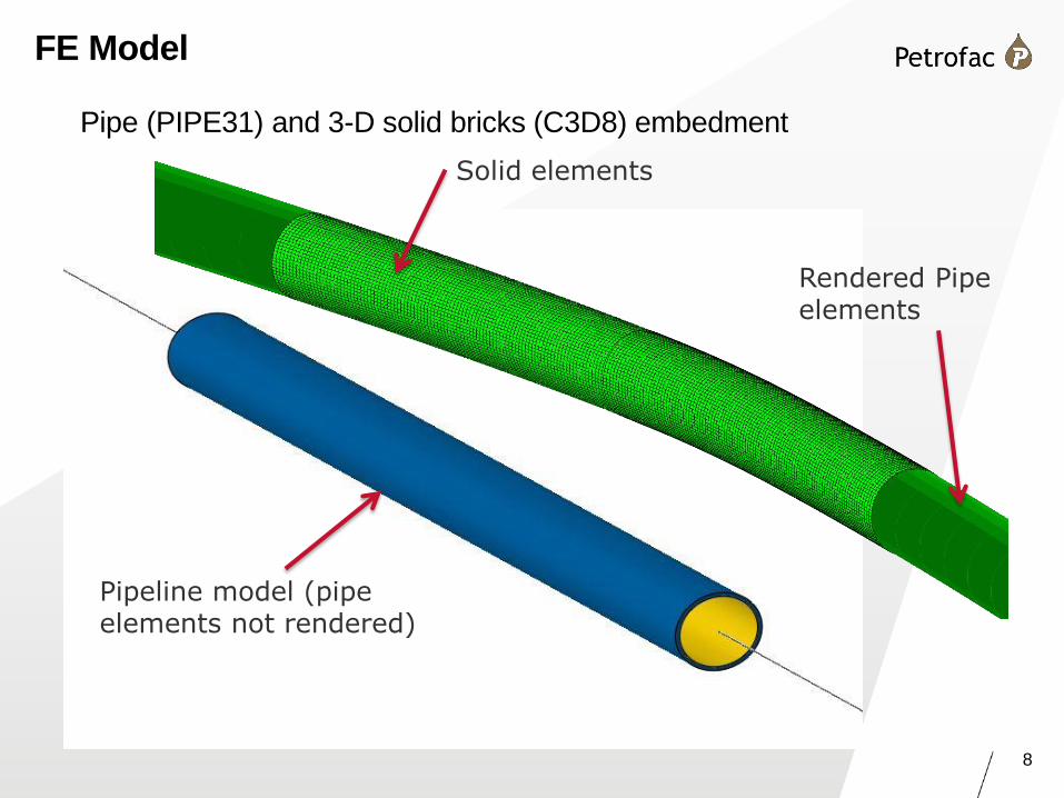
FE Model
Pipe (PIPE31) and 3-D solid bricks (C3D8) embedment
Pipeline model (pipe elements not rendered)
Solid elements
Rendered Pipe elements
9
FE Model
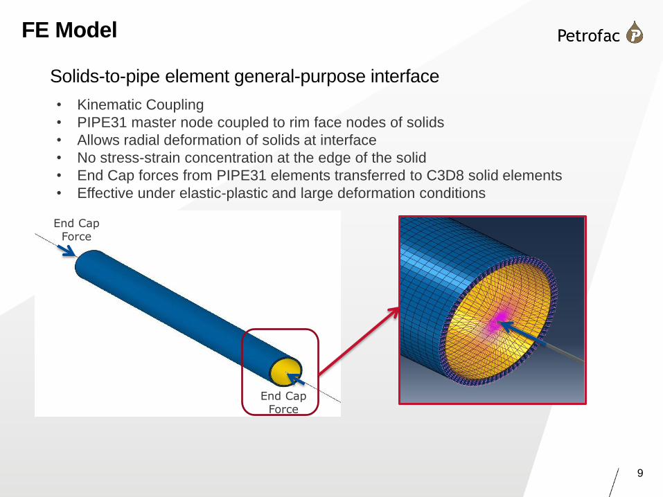
Solids-to-pipe element general-purpose interface
• Kinematic Coupling
• PIPE31 master node coupled to rim face nodes of solids
• Allows radial deformation of solids at interface
• No stress-strain concentration at the edge of the solid
• End Cap forces from PIPE31 elements transferred to C3D8 solid elements
• Effective under elastic-plastic and large deformation conditions
End Cap Force
End Cap Force
10
FE Model
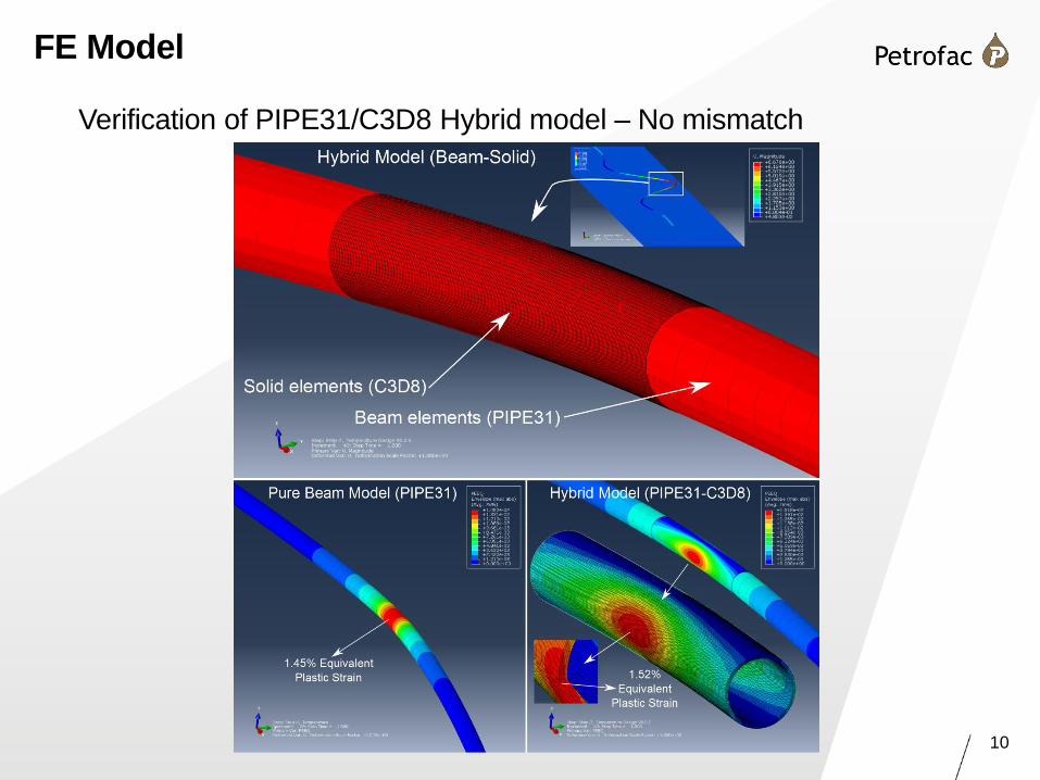
Verification of PIPE31/C3D8 Hybrid model – No mismatch
11
FE Model
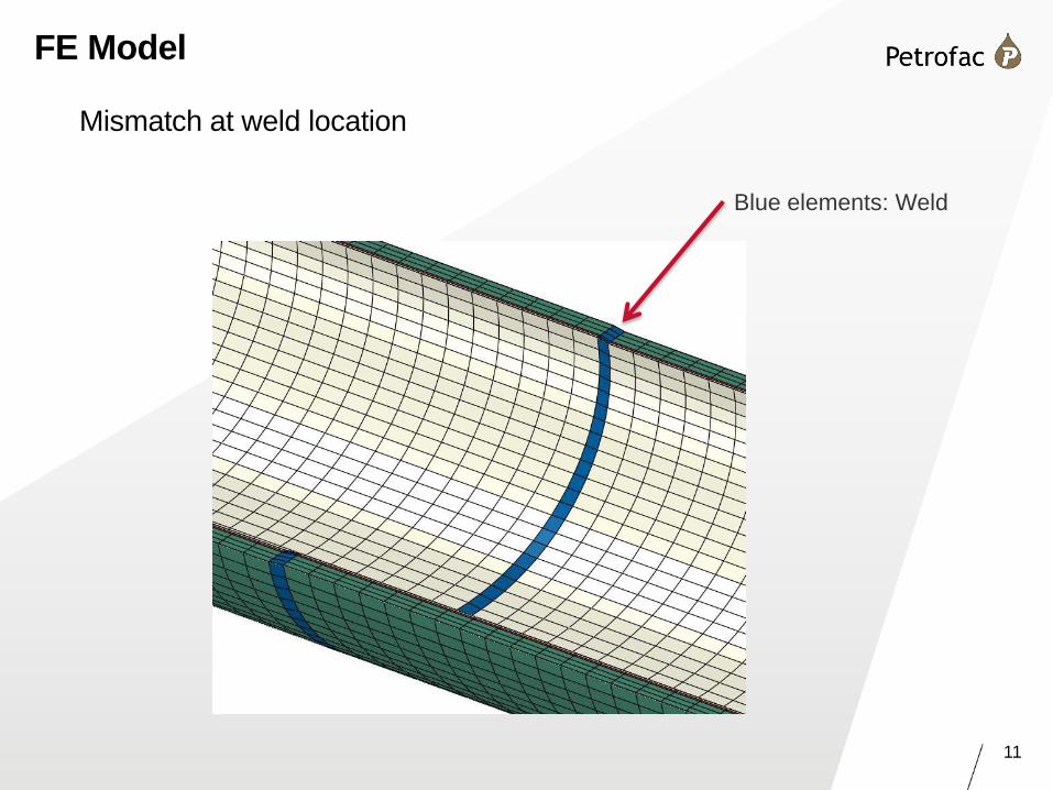
Mismatch at weld location
Blue elements: Weld
12
FE Model
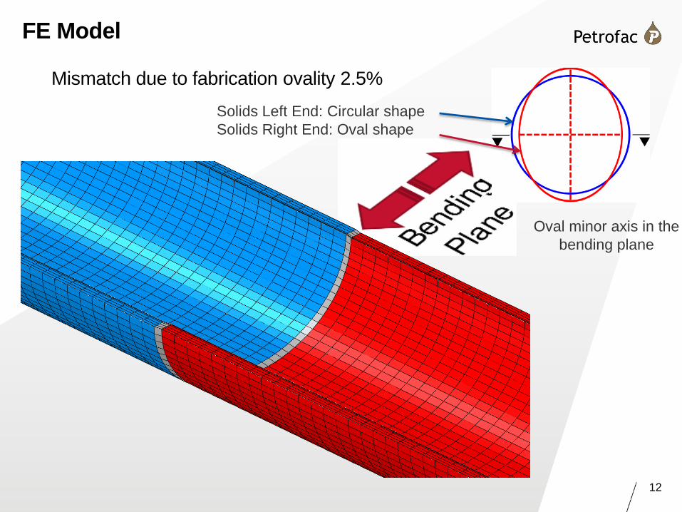
Mismatch due to fabrication ovality 2.5%
Solids Left End: Circular shape
Solids Right End: Oval shape
Oval minor axis in the
bending plane
13
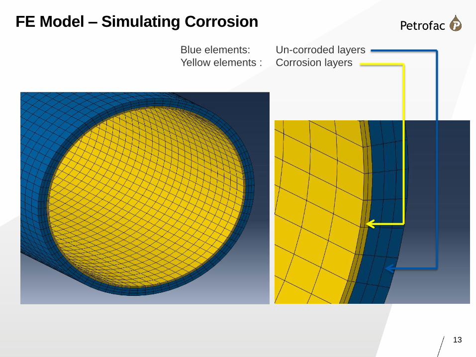
FE Model – Simulating Corrosion
Blue elements: Un-corroded layers
Yellow elements : Corrosion layers
14
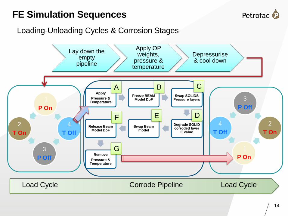
Loading-Unloading Cycles & Corrosion Stages
FE Methodology
Apply
Pressure & Temperature
Freeze BEAM Model DoF
Swap SOLIDS Pressure layers
Degrade SOLID corroded layer
E value
Swap Beam model
Release Beam Model DoF
Remove
Pressure & Temperature
Load Cycle Corrode Pipeline Load Cycle
1
P On
2
T On
3
P Off
4
T Off
3
P Off
4
T Off
1
P On
2
T On
Lay down the empty
pipeline
Apply OP weights,
pressure & temperature
Depressurise & cool down
A B C
D E F
G
FE Simulation Sequences

15
Models
• Corroded thickness is always 3.0 mm in total
• Corrosion elements removed in 1 or 2 steps (layers)
• Ovality 0% or 2.5%
• Weld overmatch 20%
• But this is NOT a parametric study
Model
name
Layers
removed
Corroded layer
thickness (mm) Beam
model
corroded
Ovality % Weld
overmatch
Layer 1 Layer 2
Model 1 1 3 - Yes 0 0%
Model 2 1 3 - Yes 0 20%
Model 3 1 3 - Yes 2.47 20%
Model 4 2 1.5 1.5 No 2.47 20%
Model 5 2 1.5 1.5 Yes 2.47 20%
Model 6
(with and
without soil
berms)
2 1 2 Yes 2.47 20%
Configurations Investigated
16
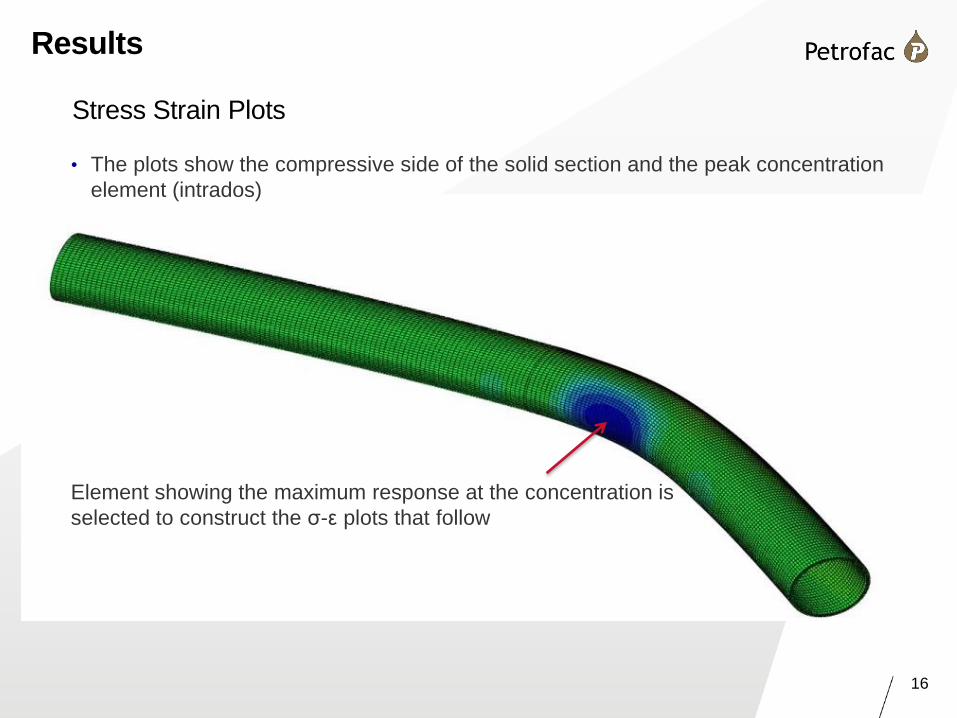
Results
Stress Strain Plots
• The plots show the compressive side of the solid section and the peak concentration
element (intrados)
Element showing the maximum response at the concentration is
selected to construct the σ-ε plots that follow
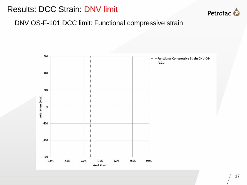
17
DNV OS-F-101 DCC limit: Functional compressive strain
Results: DCC Strain: DNV limit
18
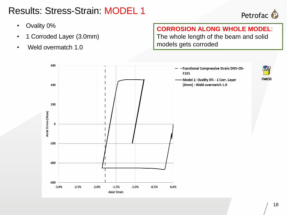
• Ovality 0%
• 1 Corroded Layer (3.0mm)
• Weld overmatch 1.0
Results: Stress-Strain: MODEL 1
CORROSION ALONG WHOLE MODEL:
The whole length of the beam and solid
models gets corroded
19
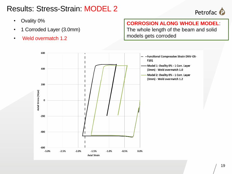
• Ovality 0%
• 1 Corroded Layer (3.0mm)
• Weld overmatch 1.2
Results: Stress-Strain::MODEL 2
CORROSION ALONG WHOLE MODEL:
The whole length of the beam and solid
models gets corroded
20
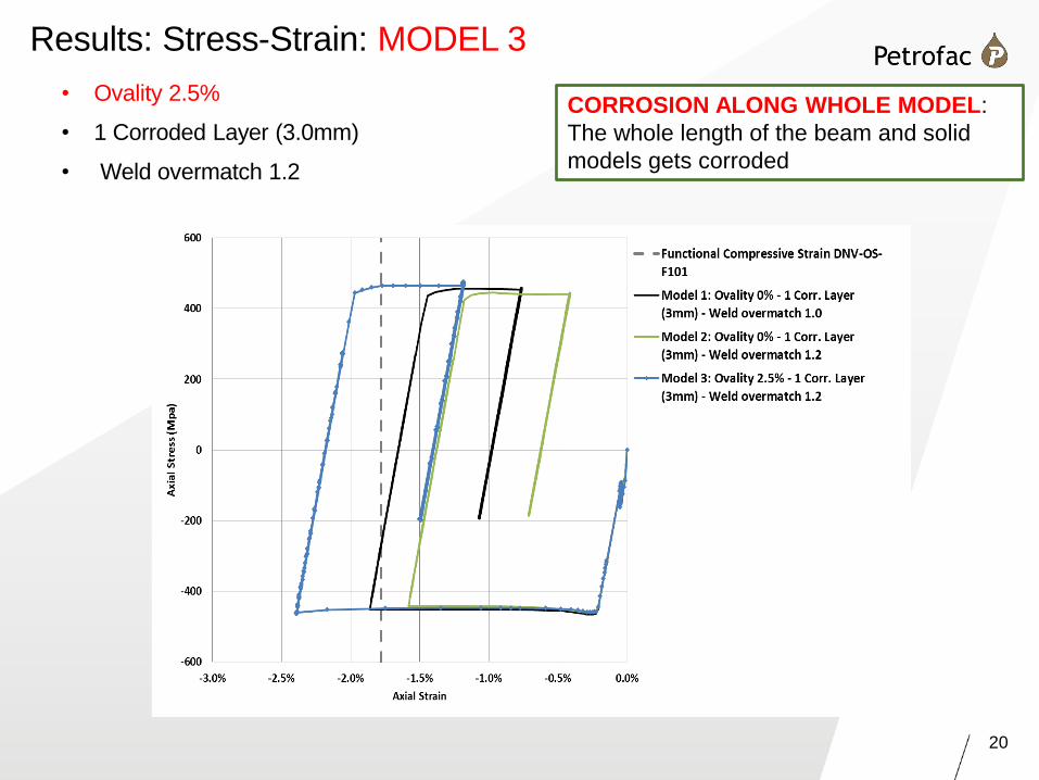
• Ovality 2.5%
• 1 Corroded Layer (3.0mm)
• Weld overmatch 1.2
Results: Stress-Strain: MODEL 3
CORROSION ALONG WHOLE MODEL:
The whole length of the beam and solid
models gets corroded
21
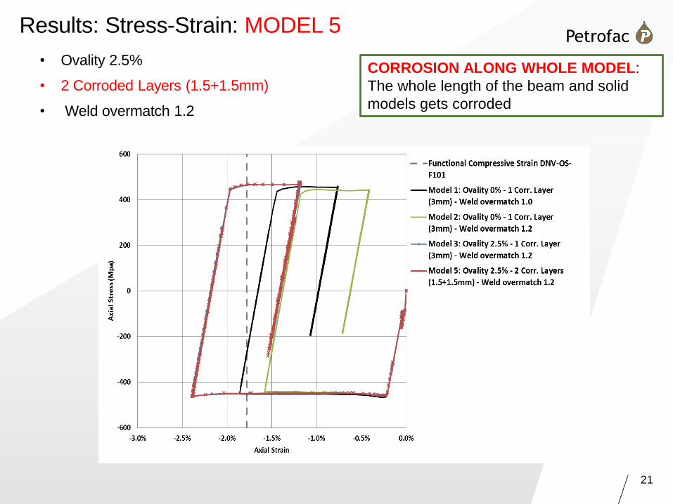
• Ovality 2.5%
• 2 Corroded Layers (1.5+1.5mm)
• Weld overmatch 1.2
Results: Stress-Strain: MODEL 5
CORROSION ALONG WHOLE MODEL:
The whole length of the beam and solid
models gets corroded
22
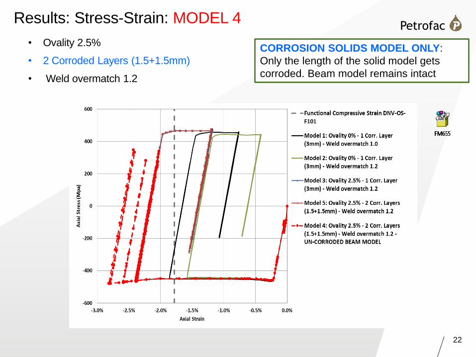
• Ovality 2.5%
• 2 Corroded Layers (1.5+1.5mm)
• Weld overmatch 1.2
Results: Stress-Strain: MODEL 4
CORROSION SOLIDS MODEL ONLY:
Only the length of the solid model gets
corroded. Beam model remains intact
23
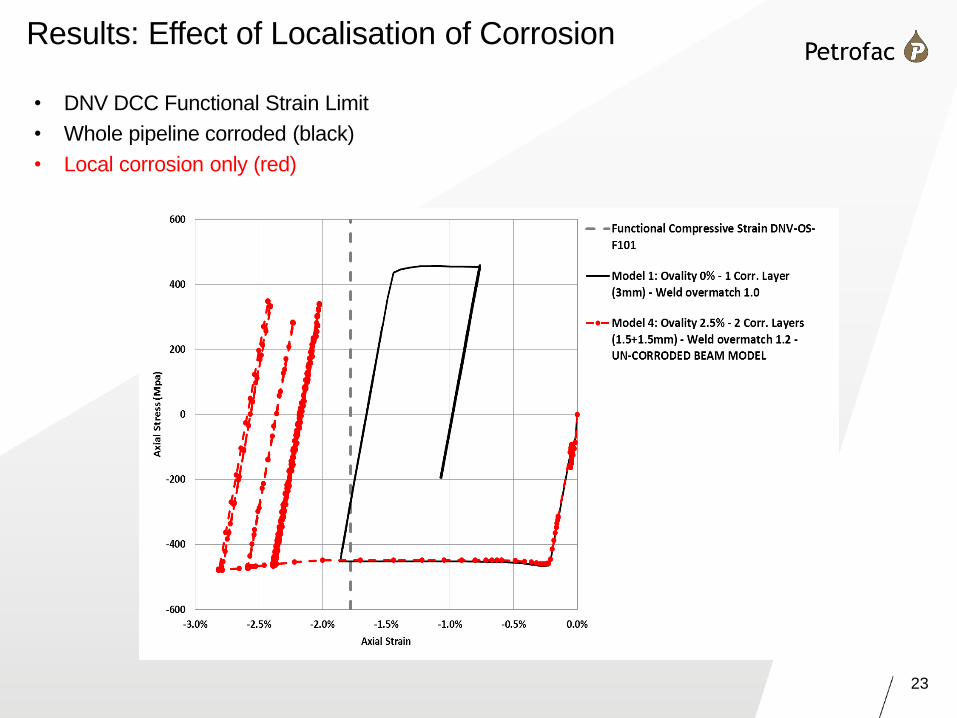
Results: Effect of Localisation of Corrosion
• DNV DCC Functional Strain Limit
• Whole pipeline corroded (black)
• Local corrosion only (red)
24
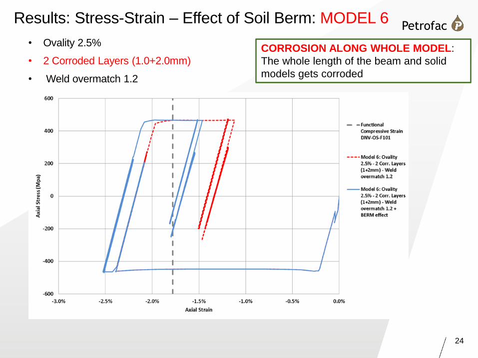
• Ovality 2.5%
• 2 Corroded Layers (1.0+2.0mm)
• Weld overmatch 1.2
Results: Stress-Strain – Effect of Soil Berm: MODEL 6
CORROSION ALONG WHOLE MODEL:
The whole length of the beam and solid
models gets corroded
25
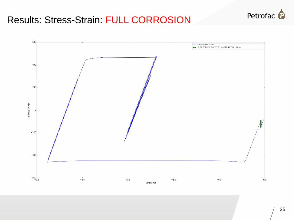
Results: Stress-Strain: FULL CORROSION
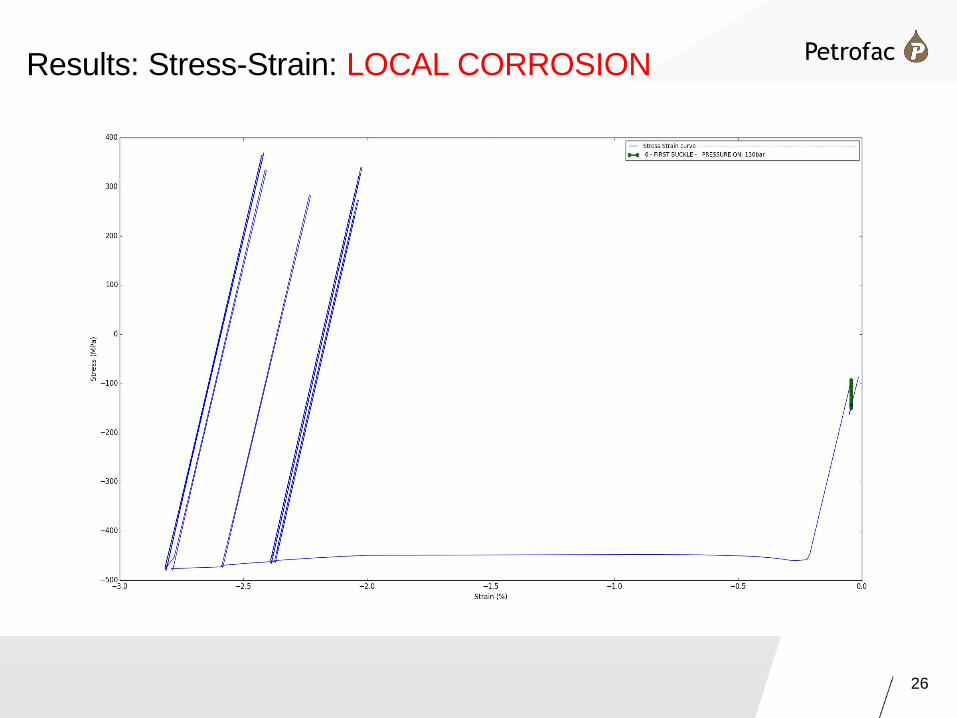
26
Results: Stress-Strain: LOCAL CORROSION
27
• No evidence of local cyclic plasticity or ratcheting at concentration
• Shakedown is achieved both locally and globally
• Soil berms restrict the range of strain on shutdown with corrosion
• But, magnitude of response depends on interpretation of DNV guidance on
corrosion
• If response obtained from nominal wall thickness is applied to corroded section as
required by DNV OS-F101 then:
- Limited ratcheting with increasing corrosion at local concentration is likely
- Target allowable strain from DNV DCC for fully corroded pipe may not be sufficient if
local concentration factor is around 2.5
• If corrosion is assumed to be over entire length of pipeline then:
- One stable reversed plasticity is likely at local concentration before shakedown
- Strain range for this cycle is not likely to be large (typically 1%)
Bulk corrosion, concentration and cyclic buckling examined
Conclusions

28
Thank You Any Questions?