effects of changing different components in a compression refrigeration system
TRANSCRIPT

1
To Study the Effects of Changing
Different Components in a
Compression Refrigeration System
Title of the Mini Project
2
Group Description
Hashim Hasnain
Hadi
Roll No: 13ME36
Ashtar Abbas
Roll No:13ME38
Ghulam Sarwar
Roll No: 13ME19
Group Advisor
Engr. Faisal Maqbool
3
Introduction of a Vapor compression
Refrigeration System:
4
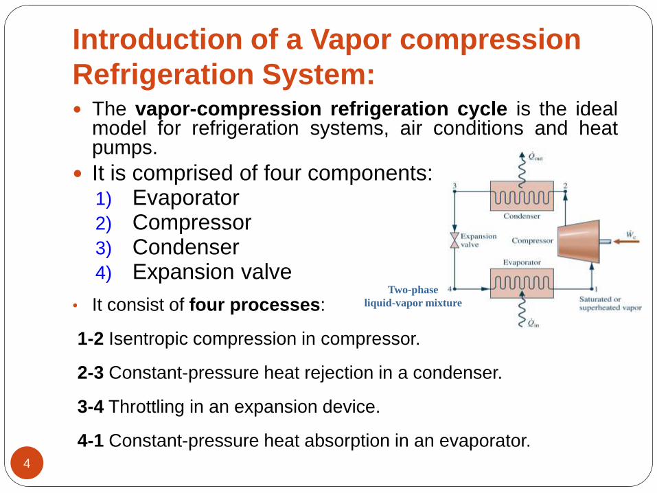
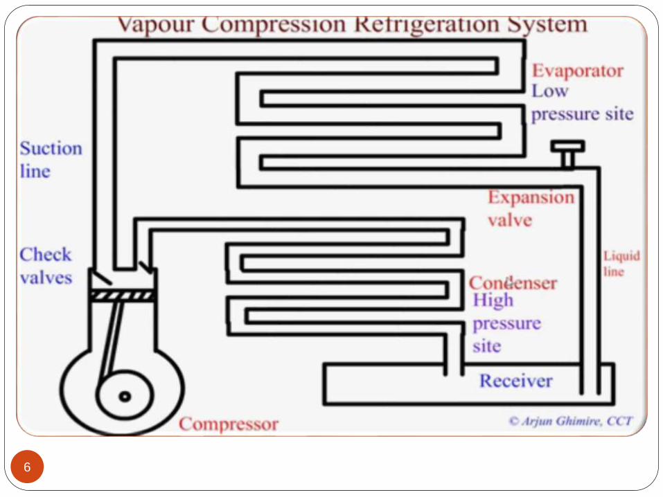
The vapor-compression refrigeration cycle is the idealmodel for refrigeration systems, air conditions and heatpumps.
It is comprised of four components:1) Evaporator2) Compressor3) Condenser4) Expansion valve
• It consist of four processes:
1-2 Isentropic compression in compressor.
2-3 Constant-pressure heat rejection in a condenser.
3-4 Throttling in an expansion device.
4-1 Constant-pressure heat absorption in an evaporator.
Two-phase
liquid-vapor mixture
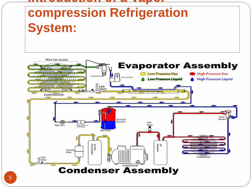
Introduction of a Vapor
compression Refrigeration
System:
5
6
`
7
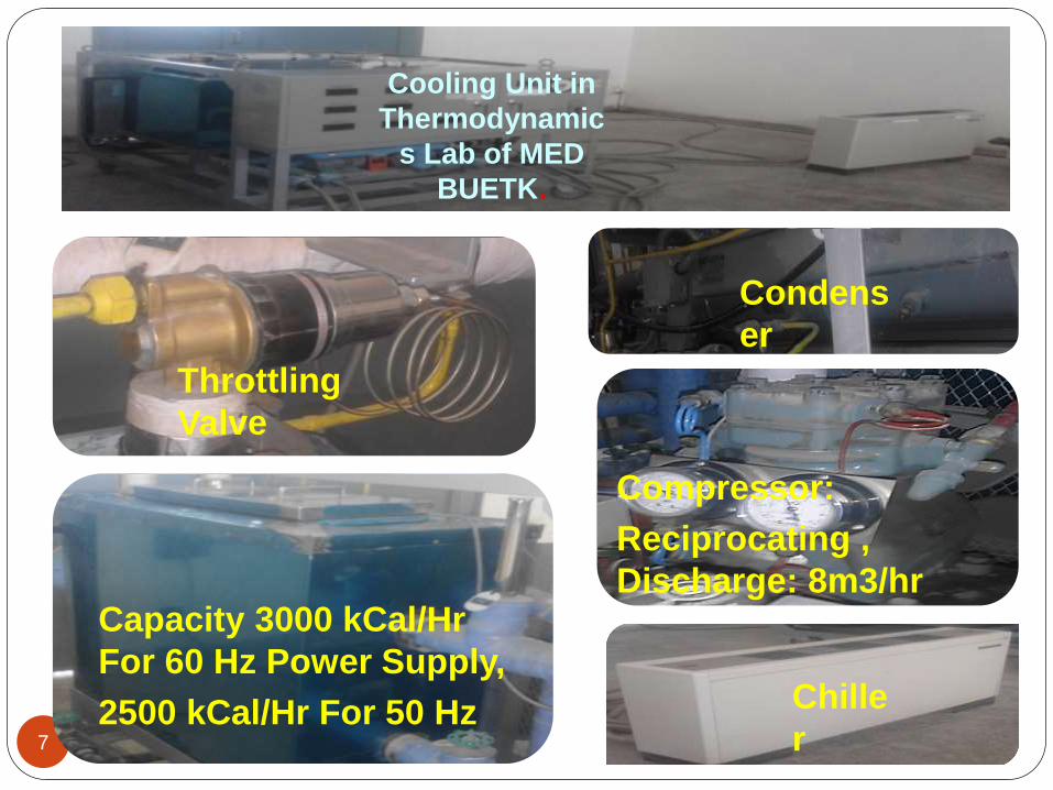
Compressor:
Reciprocating ,
Discharge: 8m3/hr
Cooling Unit in
Thermodynamic
s Lab of MED
BUETK.
Throttling
Valve
Condens
er
Capacity 3000 kCal/Hr
For 60 Hz Power Supply,
2500 kCal/Hr For 50 Hz Chille
r
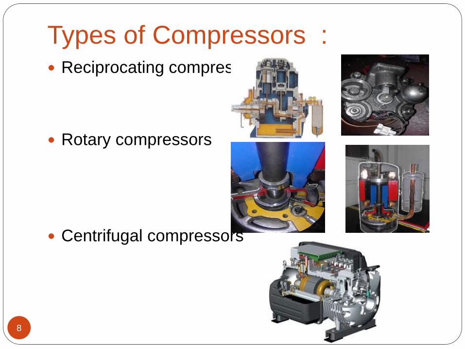
Types of Compressors :
8
Reciprocating compressors
Rotary compressors
Centrifugal compressors
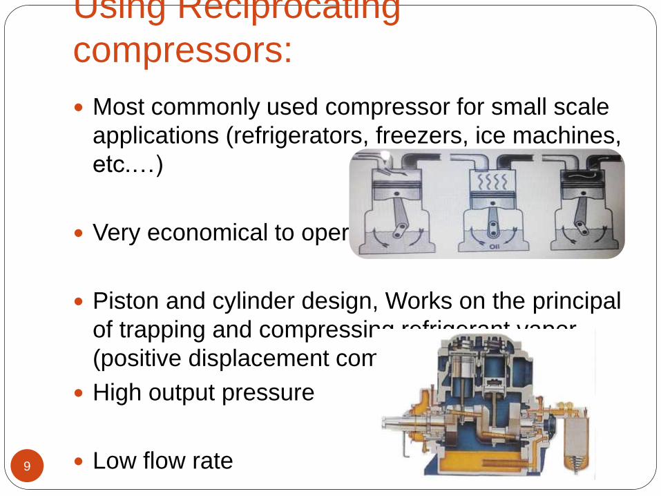
Using Reciprocating
compressors:
9
Most commonly used compressor for small scale
applications (refrigerators, freezers, ice machines,
etc.…)
Very economical to operate
Piston and cylinder design, Works on the principal
of trapping and compressing refrigerant vapor
(positive displacement compressor
High output pressure
Low flow rate
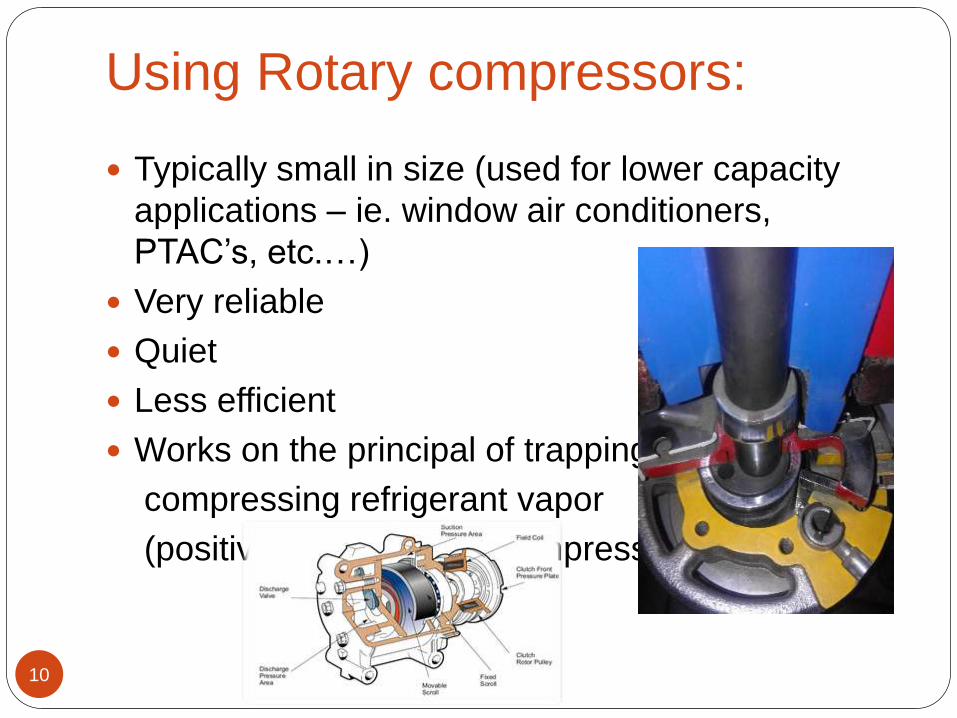
Using Rotary compressors:
10
Typically small in size (used for lower capacity
applications – ie. window air conditioners,
PTAC’s, etc.…)
Very reliable
Quiet
Less efficient
Works on the principal of trapping and
compressing refrigerant vapor
(positive-displacement compressor)
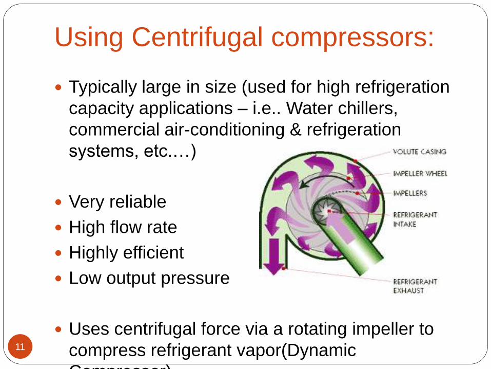
Using Centrifugal compressors:
11
Typically large in size (used for high refrigeration
capacity applications – i.e.. Water chillers,
commercial air-conditioning & refrigeration
systems, etc.…)
Very reliable
High flow rate
Highly efficient
Low output pressure
Uses centrifugal force via a rotating impeller to
compress refrigerant vapor(Dynamic
Compressor)
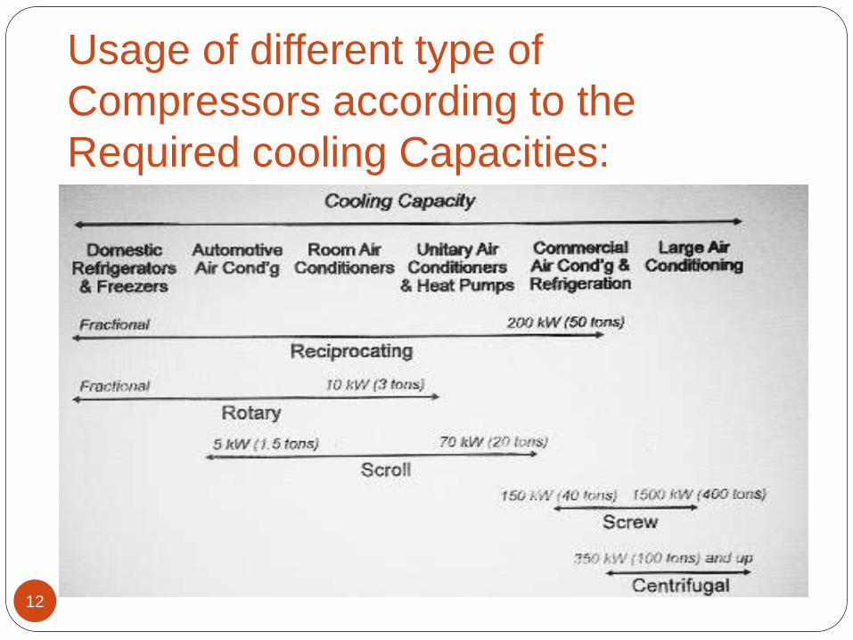
Usage of different type of
Compressors according to the
Required cooling Capacities:
12
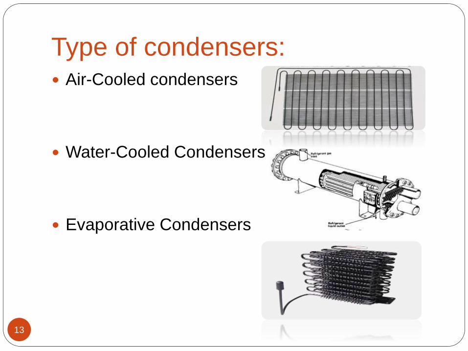
Type of condensers:
13
Air-Cooled condensers
Water-Cooled Condensers
Evaporative Condensers

Using Air-Cooled condensers:
14
Advantages:
Simple in construction__ no pipes are required for air.
Disposal of warm air not a problem
Less fouling(scaling inside tubes)
Low maintenance cost.
• Disadvantages:
Less specific heat Capacity of air
Large flow rate of air is required
Low thermal conductivity
Small heat transfer co-efficient of air
Less cop.
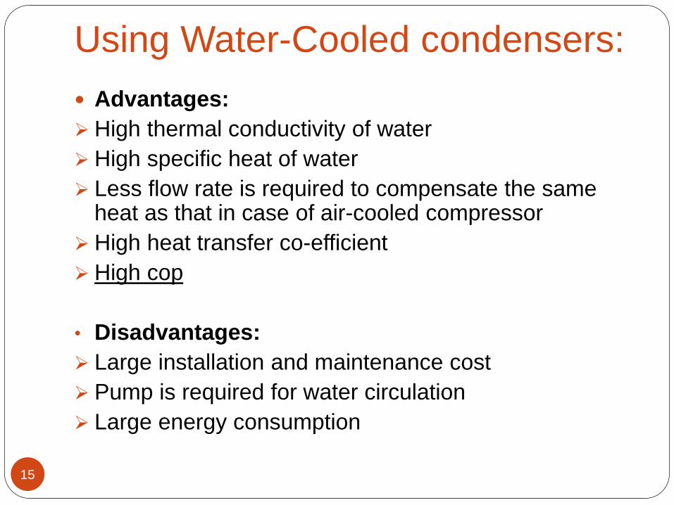
Using Water-Cooled condensers:
15
Advantages:
High thermal conductivity of water
High specific heat of water
Less flow rate is required to compensate the same heat as that in case of air-cooled compressor
High heat transfer co-efficient
High cop
• Disadvantages:
Large installation and maintenance cost
Pump is required for water circulation
Large energy consumption
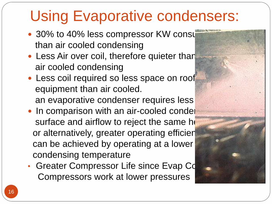
Using Evaporative condensers:
16
30% to 40% less compressor KW consumed
than air cooled condensing
Less Air over coil, therefore quieter than
air cooled condensing
Less coil required so less space on roof for
equipment than air cooled.
an evaporative condenser requires less coil.
In comparison with an air-cooled condenser,
surface and airflow to reject the same heat,
or alternatively, greater operating efficiencies
can be achieved by operating at a lower
condensing temperature
• Greater Compressor Life since Evap Condensing
Compressors work at lower pressures
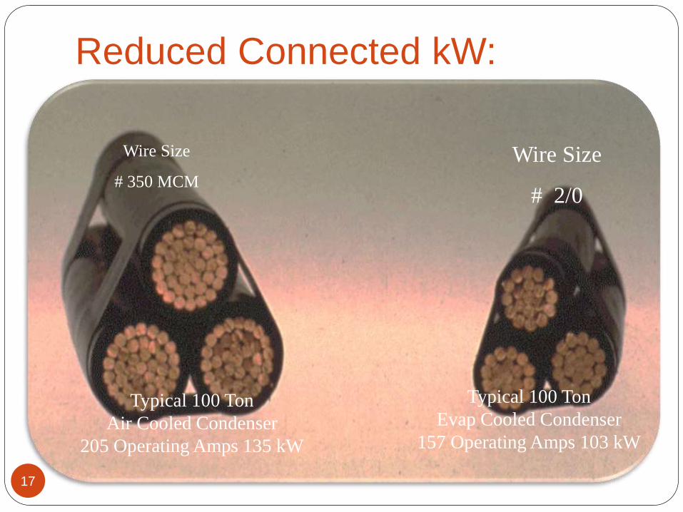
Reduced Connected kW:
17
Wire Size
# 350 MCM
Wire Size
# 2/0
Typical 100 Ton
Air Cooled Condenser
205 Operating Amps 135 kW
Typical 100 Ton
Evap Cooled Condenser
157 Operating Amps 103 kW
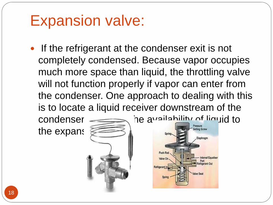
Expansion valve:
18
If the refrigerant at the condenser exit is not
completely condensed. Because vapor occupies
much more space than liquid, the throttling valve
will not function properly if vapor can enter from
the condenser. One approach to dealing with this
is to locate a liquid receiver downstream of the
condenser to assure the availability of liquid to
the expansion device
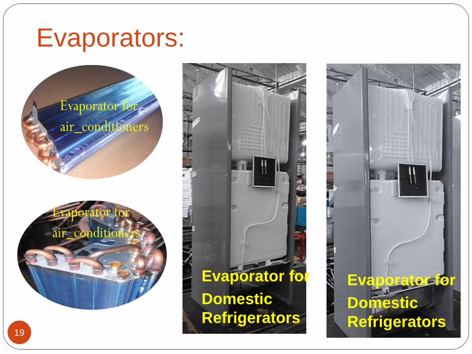
Evaporators:
19
Evaporator for
Domestic
Refrigerators
Evaporator for
Domestic
Refrigerators
Using Multi Evaporators:
20
Expansion process is one of the main factors responsible for energy loss
Not only the cooling capacity but also increase the size of evaporator.
This problem can be eliminated by adopting multi-stage expansion with flash chamber where the flash vapors is removed after each stage of expansion as a consequence there will be increase in cooling capacity and reduce the size of the evaporator.
Work input can also be reduced by replacing multi-stage compression or compound compression with single stage compression.
Refrigeration effect can also be increased by passing the refrigerant through sub cooler after condenser to evaporator.
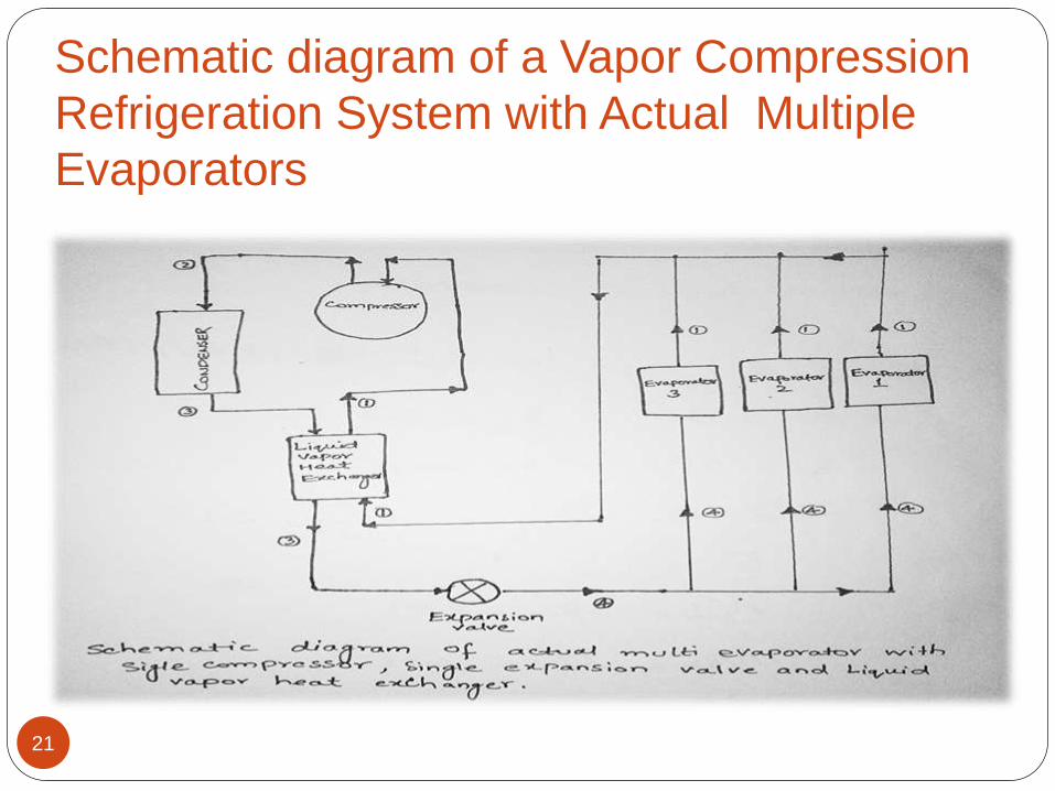
Schematic diagram of a Vapor Compression
Refrigeration System with Actual Multiple
Evaporators
21

22