effective fading reduction techniques in wireless .... 9 issue 4/version-2... · this section...
TRANSCRIPT

IOSR Journal of Electronics and Communication Engineering (IOSR-JECE)
e-ISSN: 2278-2834,p- ISSN: 2278-8735.Volume 9, Issue 4, Ver. II (Jul - Aug. 2014), PP 35-43 www.iosrjournals.org
www.iosrjournals.org 35 | Page
Effective Fading Reduction Techniques in Wireless
Communication System
1Ekwe O. A.,
2Abioye, A. E.,
3Oluwe, M. O.,
4Okoro, K.C.
1,2,3,4,Department of Electrical /Electronics Engineering, Michael Okpara University of Agriculture, Umudike,
Abia State, Nigeria
Abstract: Fading is a major impairment when transmitting a signal in wireless communication channel. It is
cause by multipath propagation. That is signals from different paths can constructively or destructively interfere
with each other. Thus, it becomes very necessary to reduce this effect, to transmit the signal effectively to the
receiver. This paper examines fading and it various types. Different techniques being employed to reduce the
effect of fading using Diversity, rake receiver and equalization are also discussed. Keywords: Diversity, Equalization, Fading, Multipath Propagation, Rake receiver
.
I. Introduction In wireless telecommunication, multi-path is the propagation phenomena that results in radio signals
reaching the receiving antenna by two or more paths. The Causes of multi-path include atmospheric scattering,
ionospheric reflection, reflection from water bodies and terrestrial objects such as mountains and buildings. [1]
Multi-path radio signal propagation occurs on all terrestrial radio links. The radio signals not only travel by the
direct line of sight (LOS) path, but as the transmitted signal does not leave the transmitting antenna in only the
direction of receiver, but over a range of angles even when a directive antenna is used. Consequently, the
transmitted signal spread out from transmitter and they will reach other objects: hills, buildings, reflection
surfaces such as the ground , water, etc. See fig. 1.
The signals may reflect of a variety of surfaces and reach the receiving antenna via paths other than the
direct LOS path. When the radio signals arrive at the receiver via variety of paths, the overall signal received is the sum of all the signals appearing at the antenna. Sometimes, these signals may be in phase with the main
signal and will add to it to increase its strength. At other times, they will be out of phase or interfere with the
main signal, therefore resulting in overall signal strength reduction.
Figure 1: Multipath Propergation
At times, there will be changes in the relative path lengths. This could result from either transmitter or
receiver moving, or any of the objects that provide a reflective surface moves. This will result in phases of the
signal arriving at the receiver changing, and in turn this will result in the signal strength varying.
When a mobile receiving antenna receive a large number of reflected and scattered signals, because of
the signal cancellation effect, the instantaneous received power seen by a moving antenna becomes a random
variable, dependent on the location of the antenna.[2]

Effective Fading Reduction Techniques in Wireless Communication System
www.iosrjournals.org 36 | Page
Since, modern wireless communication systems are typically used in urban setting, where many high buildings,
foliage and street signs are located between the transmitter and receiver, the radio transmission environment in
urban areas is characterized by multi-path propagation. [3]
II. Background Information In a typical wireless communication environment, multiple propagation paths exist between transmitter
and receiver due to scattering by different objects. Thus, copies of the signal following different paths can
undergo different attenuation, distortions, delays and phase shifts. Constructive and destructive interference can
occur at the receiver. When destructive interference occurs, the signal power can be significantly diminished.
This phenomenon is called fading.
2.1 Types Of Fading Frequency Selective fading: The transmitted signal reaching the receiver through multiple propagation paths,
having a different relative delay and amplitude. This is called multipath propagation and causes different parts
of the transmitted signal spectrum to be attenuated differently, which is known as frequency-selective fading. In
this, the channel spectral response is not flat. It has dips or fades in the response due to reflections causing cancellation of certain frequencies at the receiver.
Frequency Non-Selective fading: If all the frequency components of the signal would roughly undergo the
same degree of fading, the channel is then classified as frequency non-selective (also called flat fading).
Figure 2: Frequency selective fading
Slow fading:
Slow fading is a long-term fading effect changing the mean value of the received signal. Slow fading is
usually associated with moving away from the transmitter and experiencing the expected reduction in signal
strength. Slow fading can be caused by events such as shadowing, where a large obstruction such as a hill or
large building obscures the main signal path between the transmitter and the receiver.
Fast fading:
Fast fading is the short term component associated with multipath propagation. It is influenced by the
speed of the mobile terminal and the transmission bandwidth of the signal. In a fast fading channel, the rate of change of the channel is higher than the signal symbol period and hence the channel changes over one period
III. Methodology The methodology of this paper is based on the information gathered from research works, reports ,
journals as well as qualitative sourcing of information from the libraries which are related to this research paper.
This section describe methods that can help reduce the problem of fading in wireless communication channels
as illustrated by figure 2; they are Diversity for fast and slow fading , Equalization for flat and frequency
selection fading , Rake receiver for multipath fading and Channel Coding for deep fading.
Effective Fading Reduction Techniques in Wireless Communication System
www.iosrjournals.org 37 | Page
Figure 3:
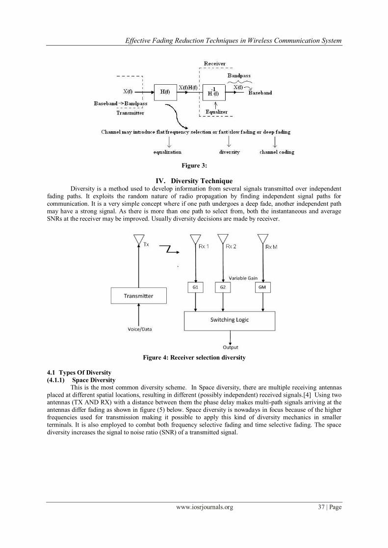
IV. Diversity Technique
Diversity is a method used to develop information from several signals transmitted over independent
fading paths. It exploits the random nature of radio propagation by finding independent signal paths for
communication. It is a very simple concept where if one path undergoes a deep fade, another independent path
may have a strong signal. As there is more than one path to select from, both the instantaneous and average
SNRs at the receiver may be improved. Usually diversity decisions are made by receiver.
Figure 4: Receiver selection diversity
4.1 Types Of Diversity
(4.1.1) Space Diversity
This is the most common diversity scheme. In Space diversity, there are multiple receiving antennas
placed at different spatial locations, resulting in different (possibly independent) received signals.[4] Using two antennas (TX AND RX) with a distance between them the phase delay makes multi-path signals arriving at the
antennas differ fading as shown in figure (5) below. Space diversity is nowadays in focus because of the higher
frequencies used for transmission making it possible to apply this kind of diversity mechanics in smaller
terminals. It is also employed to combat both frequency selective fading and time selective fading. The space
diversity increases the signal to noise ratio (SNR) of a transmitted signal.

Effective Fading Reduction Techniques in Wireless Communication System
www.iosrjournals.org 38 | Page
Figure 5: Space Diversity
(4.1.2) Frequency Diversity
In Frequency Diversity, the same information signal is transmitted and received simultaneously on two
or more independent fading carrier frequencies as shown below in Figure(6). Rationale behind this technique is
that frequencies separated by more than the coherence bandwidth of the channel will be uncorrelated and will
thus not experience the same fades. The probability of simultaneous fading will be the product of the individual
fading probabilities. The frequency diversity is use to reduce frequency selective fading.
Figure 6: Frequency Diversity
(4.1.3) Angle Diversity
Signals arriving at the antennas are coming from different directions. Being independent in their fading
variations these signals can be used for angle or angular diversity. At a mobile terminal angle diversity can be
achieved using two Omni directional antennas acting as parasitic elements to each other changing their patterns
to manage the reception of signals at different angles. As shown in figure (7), two orthogonal antennas are
employed on a single base at different angles.
Figure 7: Angle Diversity
(4.1.4) Time Diversity In time diversity, the signals representing the same information are sent over the same channel at
different times. Time diversity repeatedly transmits information at time spacing that exceeds the coherence time
of the channel. Multiple repetition of the signal will be received with independent fading conditions, thereby
providing for diversity. A redundant forward error correction code is added and the message is spread in time by
means of bit-interleaving before it is transmitted. Thus, error bursts are avoided, which simplifies the error
correction.

Effective Fading Reduction Techniques in Wireless Communication System
www.iosrjournals.org 39 | Page
Figure 8: Time Diversity
(4.1.5) Polarization Diversity Polarization Diversity relies on the de-correlation of the two receives ports to achieve diversity gain.
The two receiver ports must remain cross-polarized. Polarization Diversity at a base station does not require
antenna spacing. Polarization diversity combines pairs of antennas with orthogonal polarizations (i.e.
horizontal/vertical, ± slant 45o, Left-hand/Right-hand etc). Reflected signals can undergo polarization changes
depending on the channel. Pairing two complementary polarizations, this scheme can immunize a system from
polarization mismatches that would otherwise cause signal fade. Polarization diversity has prove valuable at
radio and mobile communication base stations since it is less susceptible to the near random orientations of transmitting antennas.
Figure 9: Polarization Diversity
4.2 Diversity Processing Techniques
Diversity processing techniques is of great importance, so as to able to combine the uncorrelated faded
signals which were obtained from the diversity branches. The diversity processing should be in such a manner
that improves the performance of the communication system like the signal to noise ratio (SNR) or the power of
the received signal at the receiving end. [5] The following diversity processing techniques are discussed below
(4.2.1) Switching In a switching receiver, the signal from only one antenna is fed to the receiver for as long as the quality
of that signal remains above some prescribed threshold. If and when the signal degrades, another antenna is
switched in. Switching is the easiest and least power consuming of the antenna diversity processing techniques
but periods of fading and de synchronization may occur while the quality of one antenna degrades and another
antenna link is established.

Effective Fading Reduction Techniques in Wireless Communication System
www.iosrjournals.org 40 | Page
Figure 10: Switching Diversity
(4.2.2) Selecting Selection processing presents only one antenna’s signal to the receiver at any given time. The antenna
chosen, however, is based on the best signal-to-noise ratio (SNR) among the received signals. This requires that
a pre-measurement take place and that all antennas have established connections (at least during the SNR
measurement) leading to a higher power requirement. [6]
The actual selection process can take place in between received packets of information. This ensures
that a single antenna connection is maintained as much as possible. Switching can then take place on a packet-
by-packet basis if necessary.
Figure 11: Selection Diversity
(4.2.3) Combining In combining, all antennas maintain established connections at all times. The signals are then combined
and presented to the receiver. Depending on the sophistication of the system, the signals can be added directly (equal gain combining) or weighted and added coherently (maximal-ratio combining) as illustrated below
Figure 12: Equal Gain Combining

Effective Fading Reduction Techniques in Wireless Communication System
www.iosrjournals.org 41 | Page
Figure 13: Maximal Ratio Combining
(4.2.4) Dynamic Control
Dynamically controlled receivers are capable of choosing from the above processing schemes for whenever the situation arises. While much more complex, they optimize the power vs. performance trade-off.
Transitions between modes and/or antenna connections are signaled by a change in the perceived quality of the
link. In situations of low fading, the receiver can employ no diversity and use the signal presented by a single
antenna. [7]
4.3 Rake Receiver
Rake receiver, used specially in CDMA cellular systems, can combine multipath components, which
are time-delayed versions of the original signal transmission. This combining is done in order to improve the
signal to noise ratio (SNR) at the receiver.
Rake receiver attempts to collect the time shifted versions of the original signal by providing a separate
correlation receiver for each of the multipath signals. This can be done due to multipath components are practically uncorrelated from another when their relative propagation delay exceeds a chip period. The design of
a rake receiver can be visualized as a series of time delayed correlator taps fed from a common antenna. [8]
If each correlator tap is delayed to match the arrival of a particular transmitted signal, then the outputs
of each tap can be recombined in phase. Once an RF signal with a particular travel time is locked onto by the
correlator tap, an estimate of the gain or loss experienced by that signal must be made. The weighting of the taps
perform this gain normalization function. Once adjusted, the outputs of each finger of the rake can be combined
to form a better version of the transmitted signal.
Figure 14 : A Rake Receiver
Each correlator detects a time-shifted version of the original CDMA transmission, and each finger of
the rake correlates to a portion of the signal, which is delayed by at least one chip in time from the other fingers. Assume M correlators are used in a CDMA receiver to capture M strongest multipath components. A weighting
network is used to provide a linear combination of the correlator output for bit decision. Correlator 1 is
synchronized to the strongest multipath m1. Multipath component m2 arrived t1 later than m1 but has low
correlation with m1.
The M decision statistics are weighted to form an overall decision statistic as shown in Figure 14. The
outputs of the M correlators are denoted as Z1, Z2 … and ZM. They are weighted by α1, α2… and αM,
respectively. The weighting coefficients are based on the power or the SNR (Signal-to- Noise Ratio) from each
correlator output. If the power or SNR is small out of a particular c’

Effective Fading Reduction Techniques in Wireless Communication System
www.iosrjournals.org 42 | Page
\orrelator, it will be assigned a small weighting factor, α If maximal-ratio combining is used, following equation
1 can be written for Z’.
The weighting coefficients, αm, are normalized to the output signal power of the correlator in such a way that the
coefficients sum to unity, as shown in equation 2.
V. Equalization Equalization compensates for Inter Symbol Interference (ISI) and deep fading created by multipath
within time dispersive channels. An equalizer within a receiver compensates for the average range of expected
channel amplitude and delay characteristics. In other words, an equalizer is a filter at the mobile receiver, whose impulse response is inverse of the channel impulse response.
As such equalizers find their use in frequency selective fading channels. In effect, an equalizer is an
inverse filter of the channel. If the channel is frequency selective, the equalizer enhances the frequency
components with small amplitudes and attenuates those with large amplitudes. The goal is for the combination
of channel and equalizer filter to provide a flat composite-received frequency response and linear phase. [9]
Figure 15: Transversal Filter equalizer (Schwartz, P49)
In the figure above, the received samples r are passed sequentially through the filter and are weighted
by the filter taps h. This can be described mathematically as:
𝑆 𝑗 = ℎ
𝑁
𝑛=−𝑁
…………… . (3)
To be able to select the filter coefficients (taps) hn to provide the greatest reduction in intersymbol
interference, the frequency response of the channel needs to be obtained. This can be done by sending known
sequences of pulses across the channel and measuring the response.[10]. Minimization algorithms can then be applied to calculate the filter coefficients so that the received
pulses match the transmitted pulses. As the channel response changes with time,mainly according to receiver
motion, equalization needs to be performed rapidly compared with rate of change of the channel properties.
VI. Channel Coding
In channel coding, redundant data bits are added in the transmitted message so that if an instantaneous
fade occurs in the channel, the data may still be recovered at the receiver without the request of retransmission.
A channel coder maps the transmitted message into another specific code sequence containing more
bits. Coded message is then modulated for transmission in the wireless channel. Channel Coding is used by the receiver to detect or correct errors introduced by the channel. Codes that used to detect errors are error detection
codes. Error correction codes can detect and correct errors under deep fading condition.
…………………….. (2)
…………………….. (1)

Effective Fading Reduction Techniques in Wireless Communication System
www.iosrjournals.org 43 | Page
VII. Conclusion This paper has examined basics of fading in wireless communication system. The effective ways of
mitigating the effect of fading using diversity, rake receiver, equalization and channel coding were also
discussed. Also from the result of this study, it is obvious that the implementation of these techniques will indeed enhance effective fading and inters symbol interference reduction in wireless communication systems.
References [1]. J. Beasley, G. Miller, Textbook on modern Electronic Communication Eight Editions. pp 736 -739, 2008.
[2]. J.J. Popoola, Simulation of Hata’s Equation for Signal Fading Mitigation. The Pacific Journal of Science and Technology available
via http://www.akamaiuniversity.us/PJST.htm. 2009.
[3]. M. Karim, M. Sarraf, Textbook on W-CDMA and CDMA 2000 for 3G Mobile Networks, Mc Graw - Hill, 2002.
[4]. S. Nitika , S. Deepak, Diversity: A Fading Reduction Technique, International Journal of Advanced Research in Computer Science
and Software Engineering Volume 2, Issue 6, ISSN: 2277 128X, 2012. Research Paper Available online at: www.ijarcsse.com.
[5]. W. Pravin, S.L. Badjate , Diversity Techniques for wireless Communication, International journal of advance research in
Engineering & Technology.(IJARET),volume 4, issue 2, march – april 2013 pp 144 - -160.
[6]. M. Simon, M. Alouini , Digital Communications over Fading Channels: A Unified Approach to Performance Analysis (New York:
John Wiley. 2000.
[7]. http://en.wikipedia.org/wiki/Antenna_diversity
[8]. T. Heikkilä, Postgraduate Course in Radio Communications. S-72.333, (2004).
[9]. T. S. Rappaport, Wireless Communications (Upper Saddle River, NJ: Prentice-Hall, 1996.
[10]. Schwartz, Mobile Communication Lecture 1,Schwartz pp49
About the Author Engr. Ekwe Ogbonna A. is a highly motivated Electronic Engineer with a bias in Communications. He
obtained his Bachelor of Engineering (B.Eng.) degree in Electronics Engineering at the University of Nigeria,
Nsukka in 2005, and a Master‟s Degree in Electronic Communications and Computer Engineering from
University of Nottingham, United Kingdom in 2011. He possesses many years of experience in different work
environments with excellent team leadership qualities. Engr. Ekwe, O. A is presently lecturing in the department
of Electrical/Electronic Engineering, Michael Okpara University of Agriculture, Umudike, Abia State, Nigeria.
His research interest are in the areas of Interference management for cellular communication, Communication
techniques for next generation cellular systems, Channel fading mitigation for fixed and mobile wireless
communication systems, etc.
Abioye. Abiodun .E. received his B.Eng. degree in Electrical Engineering from University of Ilorin, Ilorin,
Kwara State Nigeria in 2010, and currently undergoing a Master of Engineering degree in Electronics and Communication Engineering, at Michael Okpara University of Agriculture, (MOUAU) Umudike, Abia State
Nigeria. He is a member of Institute of Electrical Electronics Engineers (IEEE) and International Association of
Engineers (IAENG). His research interests are in the fields of Communication Systems, Digital Electronics,
Power Electronics and Design of Microcontroller based systems.
Oluwe Musbau O. received his B.Eng. degree in Electrical Engineering from Abubakar Tafawa Balewa
University, Bauchi, Bauchi State Nigeria in 2002, and currently undergoing a Master of Engineering degree in
Electrical/Electronics Engineering, Michael Okpara University of Agriculture, (MOUAU) Umudike, Abia State
Nigeria.
Okoro Kalu C. received his B.Eng. degree in Electrical and Electronics Engineering from Madonna University,
Nigeria in 2008, a master’s degree in Power System Engineering, University of Lagos, Nigeria in 2013. and
currently doing a Ph.D in the department of Electrical and Electronics Engineering, Michael Okpara University of Agriculture, Umudike, Abia State Nigeria. He is a member of Institute of Electrical and Electronics Engineers
(IEEE). Okoro K. C is presently lecturing in the department of Electrical/Electronic Engineering, Michael
Okpara University of Agriculture, Umudike, Abia State, Nigeria. His research interests are in the areas of
Electrical Machine drives, Power Automation Systems etc.