effect of vertex angle on elastic-plastic stability of a
TRANSCRIPT

© 2020 IAU, Arak Branch. All rights reserved.
Journal of Solid Mechanics Vol. 12, No. 4 (2020) pp. 791-803
DOI: 10.22034/jsm.2019.1873249.1462
Effect of Vertex Angle on Elastic-Plastic Stability of a Steel Open Conical Shell
H. Shokrollahi *
Department of Mechanical Engineering, Faculty of Engineering, Kharazmi University,
Tehran, Iran
Received 9 July 2020; accepted 14 September 2020
ABSTRACT
In this paper, the stability of a conical shell panel in elastic-plastic
domain is considered. The shell is made of an isotropic material
(316L steel) with linear work hardening behavior. The shell is
placed on simply supported end constraints and the acting loads are
in the form of longitudinal compressive force and lateral pressure.
The incremental Prandtl-Reuss plastic flow theory and von Mises
yield criterion are used in the analysis. The problem is formulated
based on classical shell theory and nonlinear geometrical strain-
displacement relations are assumed. The stability equations are
derived using the principle of the stationary potential energy. Using
Ritz method the equations are solved and the numerical results
obtained for different values of semi vertex and subtended angles.
The obtained results show that there is a distinct semi vertex angle
in which the shell has the best stability conditions. Also, there will
be a limiting condition for the semi vertex angels beyond which the
instability will not occur.
© 2020 IAU, Arak Branch. All rights reserved.
Keywords: Elastic-plastic; Buckling; Deformation; Conical
shell; Stability.
1 INTRODUCTION
ONICAL shell panels are one of the widely used geometrical shapes in engineering applications, especially in
aerospace and marine industries. The stability of shell structures is a very significant problem in both linear and
nonlinear analysis of these structures. To reach a good consideration of carrying capacity of the structures,
comprehensive understanding of the critical equilibrium under combined loading is needed. The stability analysis of
shells developed considerably during the years before. This development is mainly based on the computational
techniques. A comprehensive review of works published before 1982 has been presented by Bushnell [1] in which
elastic-plastic shell stability analyses and numerical methods were discussed. Zielnica [10] and [11] analyzed
elastic-plastic stability problems of conical shells. Paczos and Zielnica [6] investigated the stability of conical panels
made of two orthotropic layers. Jaskula and Zielnica [2] and Zielnica [12] presented an analysis for elastic-plastic
stability of sandwich cylindrical and conical panels, based on deformation theory of plasticity. To the best
knowledge of the authors, there are a few works in the literatures on elastic plastic analysis of conical shell panels.
______ *Corresponding author. Tel.: +98 26 34579600; Fax: +98 26 34569555.
E-mail address: [email protected] (H. Shokrollahi).
C

792 H. Shokrollahi
© 2020 IAU, Arak Branch
However elastic buckling analyses of different conical shells can be found in the literature (Naderi et al. [5],
Kouchakzadeh and Shakouri [3], Shakouri et al. [7]).
The aim of present paper is to investigate the effects of vertex angle of the shell, as a geometric parameter, on its
elastic-plastic stability. The shell is made of an isotropic elastic-plastic material (316L steel) with linear work
hardening behavior. The end edges of the shell are simply supported and the acting loads are in the form of
longitudinal compressive force and lateral pressure. The incremental Prandtl-Reuss plastic flow theory and von
Mises yield criterion are used in the analysis. The problem is formulated based on classical shell theory and the
geometrical strain-displacement relations are assumed to be nonlinear ones. The stability equations are derived using
the principle of the stationary potential energy. Using Ritz method, the equations are solved and the numerical
results obtained for different values of semi vertex and subtended angles.
2 PROBLEM DEFINITION AND ASSUMPTIONS
Fig. 1 shows an open conical shell and two different types of loadings acting on it. The acting loads are in the form
of a longitudinal compressive force, N, and a uniform lateral pressure, q. According to Fig. 1, β is subtended angle, α
is semi vertex angle, R1 and R2 are mid-plane smaller and larger radii of two curved ends, respectively, L is the
length of the shell and the shell thickness is assumed to be h and constant through the length.
Fig.1
Geometry of the conical shell and applied loading.
3 FORMULATION
3.1 Strain displacement relations
According to classical shell theory (CST), the normal and shear strains of the conical shell are as follows (Soedel
[8]):
s s s
s s s
z
0
0
0
(1)
where z denotes the shell thickness direction coordinate, s
0 and 0
are normal strains at the middle surface, s
0
is
shear strain at the middle surface and s , and
s are curvatures of the middle surface which can be expressed
in terms of the displacement components, as follows (Soedel [8]):
s
u w
s s
2
0 1
2
(2a)
v u w w
s sin s s tan s sin
2
0
2 2
1 1
2
(2b)
s
v v u w w
s s s sin s sin s
0 1 1
(2c)

Effect of Vertex Angle on Elastic-Plastic …. 793
© 2020 IAU, Arak Branch
s
w
s
2
2
(2d)
cos v w w
s ss sin s sin
2
2 2 2 2 2
1 1
(2e)
s
w w v v
s sin s s tan ss sin s tan
2
2 2
2 2 1 2
(2f)
where u, v, and w represent the displacements of the middle surface of the conical shell in the s, θ, and z directions,
respectively. In addition, the subscripts s and θ denote the meridional and circumferential directions, respectively.
3.2 Stress-strain relations
The material stress-strain curve is shown in Fig. 2. The stress-strain curve in infinitesimal strain range is presented
by a bilinear model. According to von Mises yield criterion with associated flow rule, plastic strain increment is
defined as (Washizu [9]):
p
p e
e
S3
2
(3)
where p is the plastic strain, p
e
is the equivalent plastic strain, e is the equivalent stress and S is the deviatoric
stress. The changes in stresses for an isotropic material are defined by following equations (Jaskula and Zielnica
[2]),
p
e
s s s
e
E2
2 2 121
(4a)
p
e
s s
e
E2
2 2 121
(4b)
p
e
s s s
e
E3
2 1
(4c)
where E and ν are the Young’s modulus and Poisson’s ratio, respectively. For elastic deformation the equivalent
plastic strain change, p
e , is set to zero, and with plastic deformation it can be determined according to hardening
behaviour of material. Using linear strain hardening (see Appendix A) results as:
p
e e
tE E
1 1
(5)
where Et is the tangent modulus in the plastic range and e is effective stress, defined by:
e s s s
2 2 23 (6)
Substituting p
e from Eq. (5) into Eqs. (4) and solving the system of equations for stress variations leads to
following equation,

794 H. Shokrollahi
© 2020 IAU, Arak Branch
s s
s s
C C C
C C C
C C C
11 12 13
21 22 23
31 32 33
(7)
In which the Cij (i, j= 1, 2, 3) are as follows:
t e t s s sC E E E E2 2 2 2
11 4 1 ( ) 18 1 4 1 4 1 / (8a)
t e t s s sC C E E E E2 2 2 2
12 21 {4 1 ( ) 18 2 1 5 1 2 1 }/ (8b)
s t sC C E E E13 31 3 2 1 2 / (8c)
t e t s s sC E E E E2 2 2 2
22 4 1 ( ) 18 4 1 4 1 1 / (8d)
s t sC C E E E23 32 3 1 2 2 / (8e)
t e t s s
EC E E E2 2 2 2
33 {4 1 ( )[ 5 4 2 4 5 5 4 }/2
(8f)
t e t s s sE E E2 2 2 2 21 4 1 ( ) 18 1 5 4 2 4 5 5 4 (8g)
The stresses resulted from the external loadings (Fig. 1) in pre-buckling state of stress are as follows:
a
s
N ssq s tan
h s s h
2
11 1
2
(9a)
q s tan
h
(9b)
s 0 (9c)
It is assumed that the loading parameters, q and Na, are dependent. The following parameter η, is introduced as
the ratio of lateral to longitudinal load
aN
qR1
(10)
Fig.2
Stress-strain curve for 316L steel (Lee et al. [4])

Effect of Vertex Angle on Elastic-Plastic …. 795
© 2020 IAU, Arak Branch
4 STABILITY EQUATIONS AND SOLUTION PROCEDURE
The principle of the stationary potential energy which is correct for both the pre- and post-critical deformation,
states that,
U W 0 (11)
where, U and W are the total potential energy, deformation energy and the work done by the external loadings,
respectively.
The deformation energy and the work done by the external loadings can be expressed as following (Washizu
[9]),
sh
s s s
h s
sinU C C C C s ds d dz
2
1
/ 2
2 2 2
11 12 22 33
/ 2 0
2 2
(12)
s s
a
s s
wW N s sin dsd q sin w s dsd
s
2 2
1 1
2
1
0 0
1
2
(13)
Having on hand the U and W in terms of displacement components, one can establish the expression for the total
potential energy. Implementing Eq. (11) following equation is obtained,
s
s
s
s
Eq u Eq v Eq w ds d
wBC u u BC v v BC w w BC dw ds
wBCsu u BCsv v BCsw w BCsdw d BCs w
s
2
1
2
1
0
0
( 1 2 3 )
( )
( ) 0
(14)
The terms in Eq. (14) are presented as Appendix B. As can be seen the obtained equations are highly nonlinear
and a large computation effort is needed to solve these equations directly. However, an alternative solution
procedure is used here to define unstable regions for conical shells, as presented here.
Introducing approximate functions for the displacements with unknown coefficients Ai and using Ritz method,
leads to the following equations,
iA
Π0
(15)
Application of Eq. (15) on the obtained potential energy leads to a system of nonlinear equations in terms of
unknown coefficients Ai. Solving these equations will give the displacement components in the considered shell.
The shell is assumed to be simply supported at all the edges. Geometric boundary conditions for simply supported
conical shell are as follows:
u w
v w s s s1 2
0; 0,
0 ,
(16)
To satisfy the boundary conditions (16), based on Ritz method, the following approximate functions for the
displacements are introduced (Paczos and Zielnica [6]):
m s s n
u s , A s sin cos sinL
12 2
1
(17a)

796 H. Shokrollahi
© 2020 IAU, Arak Branch
m s s n
v s , A s sin sin cosL
12 2
2
(17b)
m s s n
w s , A s sin sin sinL
12 2
3
(17c)
where A1, A2 and A3 are unknown coefficients and m and n are axial and circumferential half-wave numbers,
respectively. By comprising the total potential energy and then using the minimization principle by Eq. (15) that
is setting the partial derivatives of the total potential energy with respect to unknown coefficients Ai (i=1,2,3) to
zero, a set of three nonlinear equations in terms of unknown parameters A1, A2 and A3, is obtained as follows:
f A f A f A f A 2
11 1 12 2 13 3 14 3 0 (18a)
f A f A f A f A 2
21 1 22 2 23 3 24 3 0 (18b)
f A f A f q f A f A f A f A A f A A qf2 3
31 1 32 2 33 33 3 34 3 35 3 36 1 3 37 2 3 38 0 (18c)
where coefficients f11, f12, …, f38 and f 33 are very lengthy and for the sake of brevity they will not be given here.
These coefficients depend on geometrical and material parameters of the shell as well as the assumed half-wave
numbers m and n. Solving the above set of equations for q leads to
e A e A e Aq
e e A
2 3
1 3 2 3 3 3
4 5 3
(19)
where η is defined by Eq. (10). Note that the expressions for the coefficients ei (i=1,…,5) are very lengthy and for
the sake of brevity they will not be given here. The coefficients in Eq. (19) depend on the loading parameters q and
η. Therefore by using an iterative method the critical values of loading are obtained. To this aim, we implement an
iterative procedure similar to one introduced by Paczos and Zielnica [6], which is described briefly in the following.
Primarily, the geometrical parameters (R1, L, h, α, β) and materials constants are defined. Then the ratio of axial load
to lateral pressure (η) is assumed. Now for sequential values of A3 the corresponding loadings are calculated by
using an iterative method in which at kth
iteration, using Eq. (19) the value of q are calculated as follows:
k k k
k
k k
e A e A e Aq
e e A
1 1 12 3
1 3 2 3 3 3
1 1
4 5 3
(20)
Then the next iteration started by updating q and coefficients depending on it. The calculations are repeated until
the convergence of q is achieved. The result of above procedure is the determination of external load values (q and
Na) as functions of shell deflection.
Note that the proposed method with appropriate modification can be applied to other types of loadings. For
example for q=0, Eq. (19) can be replaced by following equation
a
e A e A e AN
e A
2 3
1 3 2 3 3 3
5 3
(21)
Moreover, the above mentioned procedure can be repeated for finding Na as a function of shell deflection. It
should be further noted that the principle of the stationary potential energy, and hence the presented analysis, is valid
only if the loading is maintained constant during the deformation.
Based on the above outlined procedure and by aids of the MATLAB program solver a self-developed computer
program is written by which the external load values (q and Na) as functions of shell deflection, and the critical
values of loading can be obtained. It should be emphasized that the presented procedure is an effective technique to
define unstable regions for conical shells.
Effect of Vertex Angle on Elastic-Plastic …. 797
© 2020 IAU, Arak Branch
5 RESULTS AND DISCUSSIONS
A conical shell panel made of 316L steel, whose stress-strain curve is shown in Fig. 2, was considered for numerical
calculations. The assumed value of the yield strength of 316L steel is 196 MPa and other material parameters are E
= 193 GPa, ν = 0.29 and Et = 1.5 GPa. The shell geometrical parameters are considered such that the instability
occurs beyond the elastic limit of the shell material. It must be emphasized that the geometrical parameters also were
chosen in a way that the instability occurs in the range of applicability of the infinitesimal theory of plasticity. In
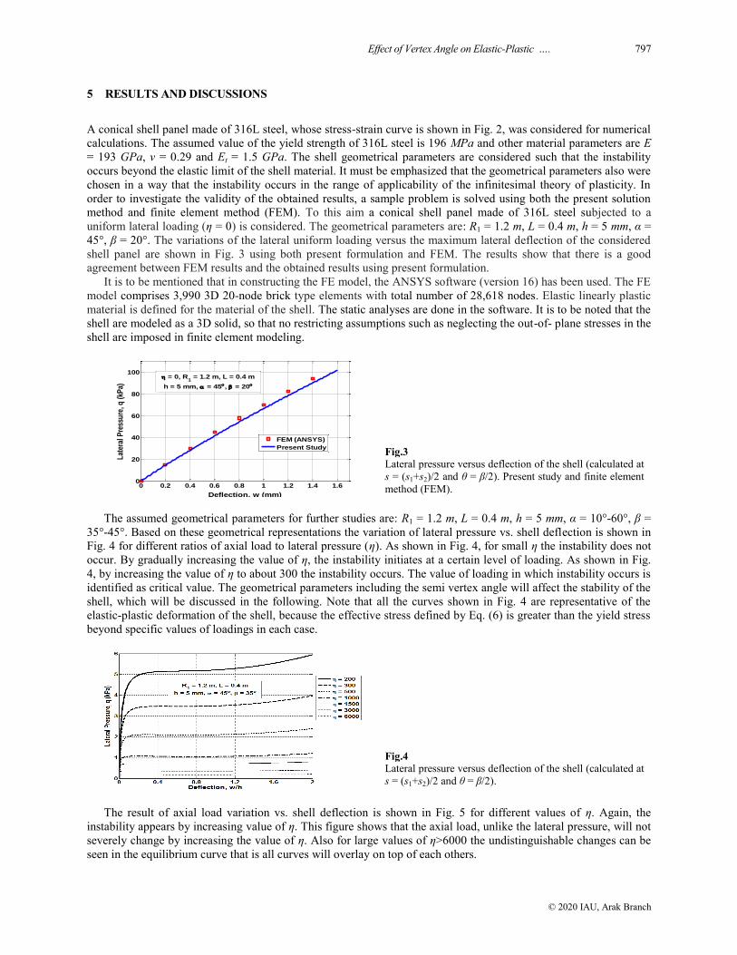
order to investigate the validity of the obtained results, a sample problem is solved using both the present solution
method and finite element method (FEM). To this aim a conical shell panel made of 316L steel subjected to a
uniform lateral loading (η = 0) is considered. The geometrical parameters are: R1 = 1.2 m, L = 0.4 m, h = 5 mm, α =
45°, β = 20°. The variations of the lateral uniform loading versus the maximum lateral deflection of the considered
shell panel are shown in Fig. 3 using both present formulation and FEM. The results show that there is a good
agreement between FEM results and the obtained results using present formulation.
It is to be mentioned that in constructing the FE model, the ANSYS software (version 16) has been used. The FE
model comprises 3,990 3D 20-node brick type elements with total number of 28,618 nodes. Elastic linearly plastic
material is defined for the material of the shell. The static analyses are done in the software. It is to be noted that the
shell are modeled as a 3D solid, so that no restricting assumptions such as neglecting the out-of- plane stresses in the
shell are imposed in finite element modeling.
0 0.2 0.4 0.6 0.8 1 1.2 1.4 1.60
20
40
60
80
100
Deflection, w (mm)
Lat
eral
Pre
ssu
re, q
(kP
a)
FEM (ANSYS)
Present Study
= 0, R1 = 1.2 m, L = 0.4 m
h = 5 mm, = 45, = 20
Fig.3
Lateral pressure versus deflection of the shell (calculated at
s = (s1+s2)/2 and θ = β/2). Present study and finite element
method (FEM).
The assumed geometrical parameters for further studies are: R1 = 1.2 m, L = 0.4 m, h = 5 mm, α = 10°-60°, β =
35°-45°. Based on these geometrical representations the variation of lateral pressure vs. shell deflection is shown in
Fig. 4 for different ratios of axial load to lateral pressure (η). As shown in Fig. 4, for small η the instability does not
occur. By gradually increasing the value of η, the instability initiates at a certain level of loading. As shown in Fig.
4, by increasing the value of η to about 300 the instability occurs. The value of loading in which instability occurs is
identified as critical value. The geometrical parameters including the semi vertex angle will affect the stability of the
shell, which will be discussed in the following. Note that all the curves shown in Fig. 4 are representative of the
elastic-plastic deformation of the shell, because the effective stress defined by Eq. (6) is greater than the yield stress
beyond specific values of loadings in each case.
Fig.4
Lateral pressure versus deflection of the shell (calculated at
s = (s1+s2)/2 and θ = β/2).
The result of axial load variation vs. shell deflection is shown in Fig. 5 for different values of η. Again, the
instability appears by increasing value of η. This figure shows that the axial load, unlike the lateral pressure, will not
severely change by increasing the value of η. Also for large values of η>6000 the undistinguishable changes can be
seen in the equilibrium curve that is all curves will overlay on top of each others.

798 H. Shokrollahi
© 2020 IAU, Arak Branch
Fig.5
Axial load versus deflection of the shell (calculated at s =
(s1+s2)/2 and θ = β/2).
The variation of critical lateral pressure versus variation of semi vertex angle for a shell with R1 = 1.2 m, L = 0.4
m, h = 5 mm, β = 35° is shown in Fig. 6. As shown in this figure, for all values of η there is a distinct semi vertex
angle in which the critical lateral pressure has a maximum value. That is the maximum critical pressure is obtained
at semi vertex angle of about 23°. One can conclude that this semi vertex angle will give the best elastic-plastic
stability for the shell panel with specified parameters and subjected to loading with large values of η.
Fig.6
Critical lateral pressure versus semi vertex angle for
different values of axial to lateral load ratio.
For the same geometrical parameter given in the above case, the variation of the critical axial loads vs. variation
of semi vertex angle for different values of η is shown in Fig. 7. The semi vertex angle related to the maximum
critical axial load in this case again is 23° that is the same as in the case of critical pressure shown in Fig. 6. As
shown in Fig. 7, for small values of η say 200, there is a limiting value for semi vertex angle (35°), beyond which
the instability does not occur.
Fig.7
Critical axial load versus semi vertex angle for different
values of axial to lateral load ratio.
The dependency of the critical loads to semi vertex angle for a shell with R1 = 1.2 m, L = 0.4 m, h = 5 mm, η =
10000 under different values of subtended angle is shown in Fig. 8. As shown in this figure, by increasing the
subtended angle the maximum value of qcr-α curve will shift to the right. In the case for the subtended shell angles
of 35, 37, 40 and 45°, the maximum critical lateral pressure will be obtained for semi vertex angles of 23.0, 25.5, 28
and 30.3°, respectively. In the results shown in this figure, for the subtended shell angles of 45° there will be a
limiting condition for the semi vertex angels beyond which the instability will not occur.

Effect of Vertex Angle on Elastic-Plastic …. 799
© 2020 IAU, Arak Branch
Fig.8
Critical lateral pressure versus semi vertex angle for
different values of subtended angle.
6 CONCLUSION
The effects of vertex angle of the conical shell, as a geometric parameter, on its elastic-plastic stability are
investigated. The shell is made of 316L steel which is an isotropic elastic-plastic material with linear work
hardening behavior. The edges of the shell are simply supported and the acting loads are in the form of longitudinal
compressive force and lateral pressure. The incremental Prandtl-Reuss plastic flow theory and von Mises yield
criterion are used in the analysis. The problem is formulated based on classical shell theory (the Kirchhoff-Love
assumptions) and the geometrical strain-displacement relations are assumed to be nonlinear ones. The stability
equations are derived using the principle of the stationary potential energy. Using Ritz method, the equations are
solved and the numerical results obtained for different values of semi vertex and subtended angles. Based on this
study, it is concluded that there is a distinct semi vertex angle in which the shell has the best elastic-plastic stability
conditions. Moreover, for specified shell geometrical and loading parameters there will be a limiting condition for
the semi vertex angels beyond which the instability will not occur.
APPENDIX A
For a linear strain hardening material, equivalent stress e is defined by:
p
e y eH0 (A.1)
where y 0 is the initial yield stress and H is the plasticity (or hardening) modulus. Then the plastic work increment
δWp is:
p p
e eW (A.2)
From Eq. (A.1) it can be concluded that
p e
eH
(A.3)
On the other hand, the plastic strain increment can be obtained from additive decomposition, as follows:
p e e e
e e e e
t tE E E E
1 1
(A.4)
Substituting p
e from Eq. (A.3) into Eq. (A.4) leads to following equation, for hardening modulus.
t
t
E EH
E E
(A.5)

800 H. Shokrollahi
© 2020 IAU, Arak Branch
APPENDIX B
L NL L NL L NLEq Eq Eq Eq Eq Eq Eq Eq Eq1 1 1 ; 2 2 2 ; 3 3 3
L NL L NL L NLBCsu BCsu BCsu BCsv BCsv BCsv BCsw BCsw BCsw; ;
L NL L NL L NLBC u BC u BC u BC v BC v BC v BC w BC w BC w; ;
L C hsinC hsin C hcos u v wEq u v w C hsin C hsin C hcos
s s s s s s
C C h C hcotv w u v uC hssin C hssin C h
s s ss s
C hcsc C hcscv u vC C h
s s s
2322 22
11 23 12
2 2 222 33 23
11 13 132 2
2 2 2
33 23
12 33 2 2
1 :
2
(B.1)
NL C C hcsc C C hcscC hw w w w w wEq C C hsin
s s s s ss
C h csc C hcscw w w w w w w w w wC h C h C hssin
s s s s ss s s
2 2 212 22 12 3323
12 11 2
22 2 2 2 223 33
13 13 112 2 2 2 2
11 :
2 2
2
(B.2)
L u v u vBCsu C h u C h v C h w C h C h C hs C hs
s s12 13 12 13 12 11 13: sin sin cos sin sin
(B.3)
NL C h w w w wBCsu C h C hs
s s s
2 2
12
13 11
csc 1: sin
2 2
(B.4)
L C h C h C h C h C hu v u vBC u u v w C h C h
s s s s s s s
23 33 23 33 23
13 33
cot csc csc:
(B.5)
NL C h C hw w w wBC u C h
s s ss
2 2 2
23 33
132
csc csc 1:
22
(B.6)
L C C h C hC hsin C h C h C hu v wEq u v w
s s s s ss
C h C hu v wC C h C h C h
s s ss s
C h C h
s
23
22 33 2323 33 23 22
3
3 3
33 23
13 23 33 232 2
3 3
23 22
3
cotsin cos cot2 :
6
cos cot cos2 sin sin cos
12 12
cot csc cot
6 1
C C hw w uC C h
s s ss s
h C hv u vC h C hs C hs
s ss s s
C C hC h w wC
ss s s
32 2 213 23
12 332 2
23 32 2 2
33
23 13 332 2 2
33 3 312 3323
2 2 2
2 cos
122
cot cos cot2 sin sin
1212
2 cotcot csc 1
12 124
wh
s
C h C hC h C hu v w
s s s s
33
13 3
2 23 32 2 322 2223 22
2 3 2 3 3
cos
cot csc cot csccsc csc
12 12
(B.7)
NL C h C hw w w w w w w w wEq C h C h C h C h
s s s s s s s s
C h C hw w w w w wC hs
s s ss s
2 2 2 2
33 23
13 33 12 33 2
22 2 222 23
13 2 2 2 2
2 csc2 : sin
csc cscsin
(B.8)

Effect of Vertex Angle on Elastic-Plastic …. 801
© 2020 IAU, Arak Branch
L C hC h u vBCsv C h u C h v C h w C h C h
s s
C h C h C hw u v wC hs C hs
s s s s ss
C h
2332333
23 33 23 33 232 2
3 3 3
33 33 23
13 332
3
23
cotcos cot: sin sin cos
6 12
cot cos cot cossin sin
12 126
cot csc
12
C hw w w
C hs ss s
32 2 2333
132 2 2
cot 1cos
6 12
(B.9)
NL C h w w w wBCsv C h C hs
s s s
2 2
23
33 13
csc 1: sin
2 2
(B.10)
L C h C hC h C hC h C h w C hu vBC v u v
s s s s ss s
C h C hC h w w u vC h C h
s ss s s
C h
2 23 3
23 2223 2322 22 22
3 3
2 23 33 222 2323
12 233 3 2 2
3
22
cot cot csccsccot csc:
6 12
cot csc cotcot csc
6 12 12
C h C hw w w
s s ss s s
3 32 2
23 12
2 2 2
cot csccot cot
1212 6
(B.11)
NL C h C hw w w wBC v C h
s s ss
2 2 2
22 23
122
csc csc 1:
22
(B.12)
L C C hC h C hC h C h uEq qs u v w
s s s ss
C h C h C hC h C h C h v u vC h C h
s s ss s s s s
C C
3
23 1323 2322 22
3
3 3 33 3
33 23 1322 22 12
12 233 3 3 2 2
23 1
coscos cotcos cos cot3 : sin
3
cos coscot cos cos
3 6 6 4 3
a
h C C C h C C hC hw w v w
s s ss s s s
C C C h C C h C C hw w v
ss s s s
C h wN s C h
s s
3 3 33 2 23 22 12 33 23 1322
3 2 2 2
3 3 32 3 212 22 33 12 33 23 13
3 2 2 2 2
3 2322
1 112
2 4 cotsin
3 12 12 3
2 csc 2 csc 2 cos
126 6
sin 1sin s
12 6
C hC hw v w
s s s
C h C h C hC hv w v w
s s s s s s
C C h w wC h C
s s s
2333 2 32323
3 3 2 3 3
2 3 23 3 333 4 3 422 22 2323
3 3 3 4 2 2 2 3
3 4 412 33 3
132 2 3
csccot cscin
3 3
cot csc csc csccot csc
12 12 4 3
2 csc 1 1
6 3 12
C C hv v wh C h s
ss s s
33 3 412 333 3
13 113 2 4
2 cot 1cos sin
12 12
(B.13)
NL C h C h C h C h C h C hw u w w v w w wEq u v v w
s s s s s ss s s
C C hC h C h C hw w w u w u ww
s s s s s ss
C hC h v w
s s
2
23 23 33 33 33 23
2 2 2
2 233 2223 23 33
2
22323
2 cot3 :
csccot 2 cot 2 csc
csc2 csc
w w u w vC h C h
s s s
u w w w wC C h C h u C h v C h
s s ss s
w u w u w v w v wC h w C h C h C C h C h
s s s ss s
2 3 2 2
13 333 2 2
22 2
12 11 12 13 122 2
2 2 2 2 2
12 13 13 12 33 122 2
1sin sin sin cos
2
cos 2
s
C C h C C hw w w w u wC hs
s s ss s s
u w v w v w w w wC hs C hs C hs C h
s s s ss s s s
2
2 2 2 212 33 12 33
112 2 2
2 2 2 2
11 13 13 132 2 2 2
2 csc 2 cscsin
22
sin sin sin 3
(B.14)

802 H. Shokrollahi
© 2020 IAU, Arak Branch
C hC hw w w w v wC h C hs u
s s s s s
C hC h C h C hw w w u wv w
s s s s
C h u w
s
3 2 2 2
2322
11 11 2 2 2 2
222 2 22323 22 22
2 2 2 2 2 2 2
2 223
2 2
2 csccsc1 3sin sin
2 2
csccsc cot csc cot csc
2
csc
C h C h C hv w v w w w
s s s
C C h C h C hC h w u w u w v w v
s s s s s s s s
C h C h C hu w w vu
s s s s s
2 2 3 22 2 222 22 22
2 2 2 2 3 2
2 2 2 212 33 23 2312
2 2
2
23 23 33
csc csc csc3
2
csc csc 2 csccsc
2
C h C hw u w v w
s s s s s
C h C hw w w w w u w v wC h C h
s s s s s ss s
C C hC hC h w w w
s s s s
2 2
33 23
2 2
2 2 22 2 2 223 23
13 332 2 2
2212 333312
2
csc csc
3 csc 3 csc2 2
2 4 csccsccsc
2
w w w wC h
s s s s
22 2
133
(B.14)
L
a
C C h C C C h C C h C hv w wBCsw v
s s s s
C C h C C h C hC hw v w w
s s s s s ss
wC h
s
3 3 3 3 223 13 12 22 33 23 13 22
2 2 2 2 2
3 3 332 212 33 23 13 1322
12 2
23
11
cos 4 cot csc:
6 12 6 12
4 csc 2 cos sinN s sin
12 12 612
1sin
12
C h C C hC h v w v
s ss s
C C h w w v wC h C h C h s
s s s s s
23 33 2 3 223 12 3323
2 2 2 2 3
3 3 3 2 312 33 3 3 3
13 13 112 2 2 3
csc 2 cotcot csc
126 6
4 csc 1 1 1cos sin
12 3 12 12
(B.15)
NL C hC h C h C h C h C hw w w u w v w wBCsw u v w
s s s s s s
w u w v w w w u wC h C h C h u C h v C h w C h
s s s s s s
Cv wC h
s
2 3
2323 33 23 33 23
2
13 33 12 13 12 13
1
12
csccot csc csc:
2
sin sin cos
C h w w u w v wC hs C hs
s s s s s s
w w wC h C hs
s s
2
2 33
11 13
2 3
13 11
2 cscsin sin
2
3 1sin
2 2
(B.16)
L C hC h C h C h C hv w w vBC w v
ss s s s s
C C h C C h C hw w v
s ss s s
C h C hw
s
233 3 3 322333 23 33 33
3 3 3 3 2 2
23 3 32 2 233 22 13 23 22
2 2 3 2
33 3322 23
3 3
csccot cot csc csc cot:
3 3 3 3 3
4 csc cot csc
612 12
csc cot csc
12 4
C hv w
ss s s
C C h C hw w vC h
s ss s s
232 323
2 2 2
3 33 3 212 33 3 33
132 3 2
csc
3
4 csc cot1
12 6 6
(B.17)
NL C h C hC hC h C hw w w u w v wBC w u v w
s s s s s
C h C h C h C h C hC hw w u w v w w wu v w
s s s s s s s s s ss
C h
2 2
23 222322 22
2 2 2 2 2
3 3
22 23 23 33 2312
3
33
csc csccsccsc cot csc:
csc csc cotcsc
2
C hC hu w v w w w u w v wC h C h
s s s s s s s s ss
C C h w w wC h
s s s
2 2
2323
13 332
2 3
12 33
13
3 csccsc csc
2
2 csc 1
2 2
(B.18)

Effect of Vertex Angle on Elastic-Plastic …. 803
© 2020 IAU, Arak Branch
C h C hC h C hv w w v wBCsdw v C h C h
s s s s s s
w wC h C h s
s s
3 33 3 23 313 1312 12
13 122
2 23 3
13 11 2
cos cot csc 1 1: cos sin
6 12 6 12 12 12
1 1sin
6 12
(B.19)
C h C h C hC h v w wBC dw v
s s s s
C hC h C h C hv w w w
s s s ss s s s
2 2 33 3 33 222 23 2223
3 3 3 3 2
233 3 32 22323 22 12
2 2 2 2
cot csc csc csccot csc:
6 12 6 12
csccot csc csc csc
1212 12 6
(B.20)
C hC h C h C h C hv w w vBCs w v
s ss s s s
C h C hw w wC h
s s s s s
233 3 3 322333 23 33 33
2 2 2 2 2
3 3 2 2323 33
13 2
csccot cot csc csc cot:
63 6 3 6
csc 1
6 3 6
(B.21)
REFERENCES
[1] Bushnell D., 1982, Plastic buckling of various shells, Jornal of Pressure Vessel Technology 104: 51-72.
[2] Jaskula L., Zielnica J., 2011, Large displacement stability analysis of elastic-plastic unsymmetrical sandwich
cylindrical shells, Thin-walled Structures 49: 611-617.
[3] Kouchakzadeh M.A., Shakouri M., 2015, Analytical solution for axisymmetric buckling of joined conical shells under
axial compression, Structural Engineering and Mechanics 54(4): 649-664.
[4] Lee W.S., Lin C.F., Liu T.J., 2006, Strain rate dependence of impact properties of sintered 316L stainless steel, Journal
of Nuclear Materials 359: 247-257.
[5] Naderi A.A., Rahimi G.H., Arefi M., 2014, Influence of fiber paths on buckling load of tailored conical shells,
Steel & Composite Structures 16(4): 375-387.
[6] Paczos P., Zielnica J., 2008, Stability of orthotropic elastic–plastic open conical shells, Thin-Walled Structures 46: 530-
540.
[7] Shakouri M., Spagnoli A., Kouchakzadeh M.A., 2016, Effects of imperfection shapes on buckling of conical shells
under compression, Structural Engineering and Mechanics 60(3): 365-386.
[8] Soedel W., 2004, Vibrations of Shells and Plates, Marcel Dekker Inc., New York, USA.
[9] Washizu K., 1975, Variational Methods in Elasticity and Plasticity, Pergamon Press, Oxford, UK.
[10] Zielnica J., 1981, Elastic plastic buckling of sandwich conical shells under axial compression, Bulletin de
l'Académie Polonaise des Sciences / Série des Sciences Techniques 29: 239-251.
[11] Zielnica J., 2003, Non-linear stability of elastic–plastic conical shell under combined load, Journal of Theoretical and
Applied Mechanics 41: 693-709.
[12] Zielnica J., 2012, Buckling and stability of elastic-plastic sandwich conical shells, Steel & Composite Structures 13(2):
157-169.