effect of the staggered impeller on reducing unsteady
TRANSCRIPT

Effect of the staggered impeller on reducingunsteady pressure pulsations of a centrifugal pumpNing Zhang ( [email protected] )
Jiangsu UniversityJunxian Jiang
Jiangsu UniversityXiaokai Liu
Jiangsu UniversityBo Gao
Jiangsu University
Research Article
Keywords: staggered impeller, centrifugal pump, numerical simulation, reduction of pressure pulsation
Posted Date: April 5th, 2021
DOI: https://doi.org/10.21203/rs.3.rs-308478/v1
License: This work is licensed under a Creative Commons Attribution 4.0 International License. Read Full License
1
Effect of the staggered impeller on reducing unsteady pressure pulsations of a centrifugal pump
Ning Zhang1, Junxian Jiang1, Xiaokai Liu1, Bo Gao1 1School of Energy and Power Engineering, Jiangsu University, Zhenjiang, 212013, China
Abstract: High pressure pulsations excited by rotor stator interaction is always focused in pumps, especially for its control considering the stable operation. In the current research, a special staggered impeller is proposed to reduce intense pressure pulsations of a centrifugal pump with ns=69 based on alleviating rotor stator interaction. The numerical simulation method is conducted to illustrate the influence of staggered impeller on the pump performance and pressure pulsations, and three typical flow rates (0.8ФN-1.2ФN) are simulated. Results show that the staggered impeller will lead to the pump head increasing, and at the design working condition, the increment reaches about 3% compared with the original impeller. Meanwhile, the pump efficiency is little affected by the staggered impeller, which is almost identical with the original impeller. From comparison of pressure spectra at twenty monitoring points around the impeller outlet, it is validated that the staggered impeller contributes significantly to decreasing pressure pulsations at the concerned working conditions. At the blade passing frequency, the averaged reduction of twenty points reaches 89% by using the staggered impeller at 1.0ФN. The reduction reaches to 90%, 80% at 0.8ФN, 1.2ФN respectively. Caused by the rib within the staggered impeller, the internal flow field in the blade channel will be affected. Finally, it is concluded that the proposed staggered impeller surely has a significant effect on alleviating intense pressure pulsation of the model pump, which is very promising during the low noise pump design considering its feasibility for manufacturing. Keywords: staggered impeller, centrifugal pump, numerical simulation, reduction of pressure pulsation
Nomenclature
Qd Pump capacity, m3/h Hd Design head, m nd Design speed, r/min ns Specific speed ΦN Flow coefficient ΨN Head coefficient Z Blade number η Efficiency D1 Impeller suction diameter, mm D2 Impeller exit diameter, mm D4 Volute exit diameter, mm b2 Impeller exit width, mm ϕ Wrap angle of the blade,° u2 Peripheral speed at the blade outlet, m/s δ Rib width, mm ρ Water density, m3/h A Pressure value, Pa cp Pressure coefficient θ Angle of the monitoring point, ° w Relative velocity, m/s Ωz Vorticity magnitude along z direction, 1/s y+ y plus value Δt CFD time step, s fn Rotating frequency, Hz fBPF Blade passing frequency, Hz
Introduction
As the general and common machinery, pumps are used in almost all the industrial fields, and the corresponding stable operation are strictly required in special fields, for example the nuclear power plant and petrochemical industry[1,2]. As for the stable and safe working of the pump, it is considered to be associated with the flow induced pressure pulsations, which is mainly originated by the rotor-stator interaction(RSI)[3-4]. So, pressure pulsations are always emphasized and
2
investigated during the pump design and its operation[5]. For pressure pulsation in centrifugal pumps, two topics are mainly discussed, namely the generating mechanism and
the corresponding control. RSI resulted by the impeller periodically sweeping the tongue is the primary factor accounting for high and intense pressure pulsations in centrifugal pumps, which is investigated and validated by many researchers[6,7]. Pressure spectral characteristics at different working conditions were clarified. It was found that pressure signals show periodic characteristic at the design working condition. In pressure spectrum, caused by RSI effect, the discrete peaks at fBPF (blade passing frequency) and its high harmonics with lower amplitudes could be captured[8,9]. So, the frequency at fBPF keeps the predominant role in spectrum as manifested by the maximum pressure magnitude when the centrifugal pump works around the nominal flow rate as pointed by Yao et al[10]. At off-design flow rates, pressure pulsation amplitude at fBPF will be affected[11]. At low flow rate, the flow separation with large scale in the blade channel will lead to the increment of pressure pulsation, and at high work conditions, the stronger interacting effect between the non-uniform fluid and the tongue will also lead to high pressure pulsation. It means that pressure pulsation will be minimized around the design working condition[12].
As for the control of pressure pulsation, the RSI effect is mainly concentrated, and some effective approaches were discussed. Yang et al proved that the rotor-stator gap is crucial for pressure pulsations, and positive effect will be generated by increasing the gap[13]. Posa et al also validated that the large gap will be beneficial for reducing pressure pulsation amplitude by rotating the diffuser blade around the middle chord[14]. Al-Qutub et al discussed the influecne of blade V-cut on complex pressure pulsation, and it is validated that the V-cut can reduce pressure pulsations[15]. Recently, many researchers believe that the rotor-stator interaction is determined by the flow distribution at the blade trailing edge (BTE), and by controlling the flow distribution at trailing edge of the impeller, unsteady pressure pulsation energy could be decreased[16]. From such point, Gao et al analyzed the effect of BTE shape on pump performance and unsteady pressure pulsation, and results show that the BTE shape surely affects pressure pulsation energy[17,18]. The reason is due to the changing of flow distribution by modifying the BTE shape, and the flow uniformity could be improved significantly by the reasonable BTE shape. Based on the published works, unsteady pressure pulsation energy within the centrifugal pump is affected by two factors, and one is the fluid distribution characteristics at the BTE and the other is the corresponding intense interacting effect with the tongue. So, if we can control and reduce the striking effect between the fluid discharged from the BTE and the volute tongue, then pressure pulsation energy could be decreased[19-21]. For the commonly used impeller, when the wrap angles from the shroud to the hub streamlines are identical, fluid discharged from the impeller will hit and interact with the tongue simultaneously[22,23], namely with the same phase. Finally, high pressure pulsations will be excited. It is inferred that if the flow from the shroud to the hub does not interact with the tongue simultaneously, namely the phase difference is generated by some special impeller types, then pressure pulsation may be reduced. Based on the above analysis and assumption, in the current paper, a special staggered impeller is proposed to reduce pressure pulsations in a centrifugal pump. The impeller is divided into two sections by a rib in the middle plane, and the phase difference will be generated. To investigate effect of the staggered impeller on the pump performance and complex pressure pulsation, the unsteady numerical simulation method was applied, and the corresponding accuracy was validated by the experiment. Emphasis was laid on the resulting influence on pressure pulsations, and twenty monitoring points were placed around the impeller exit to extract pressure signals and to evaluate the positive effect comprehensively. Meanwhile, three typical flow rates were carried out for the staggered impeller, which were compared with the original impeller in detail. Finally, the effect of staggered impeller on the performance and pressure pulsation will be clarified. The obtained results in the present paper will provide a direction to control pressure pulsation energy in centrifugal pump considering its strong maneuverability.
1. Numerical setup
1.1 Model pump for investigation
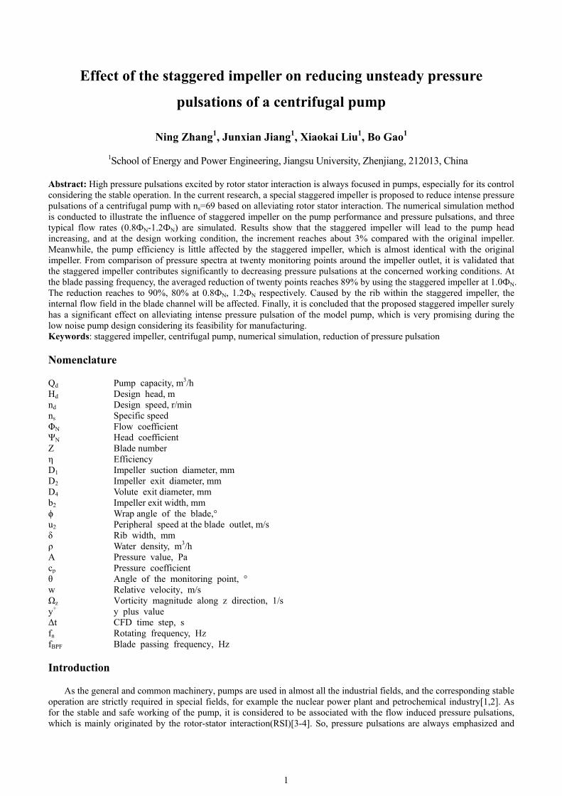
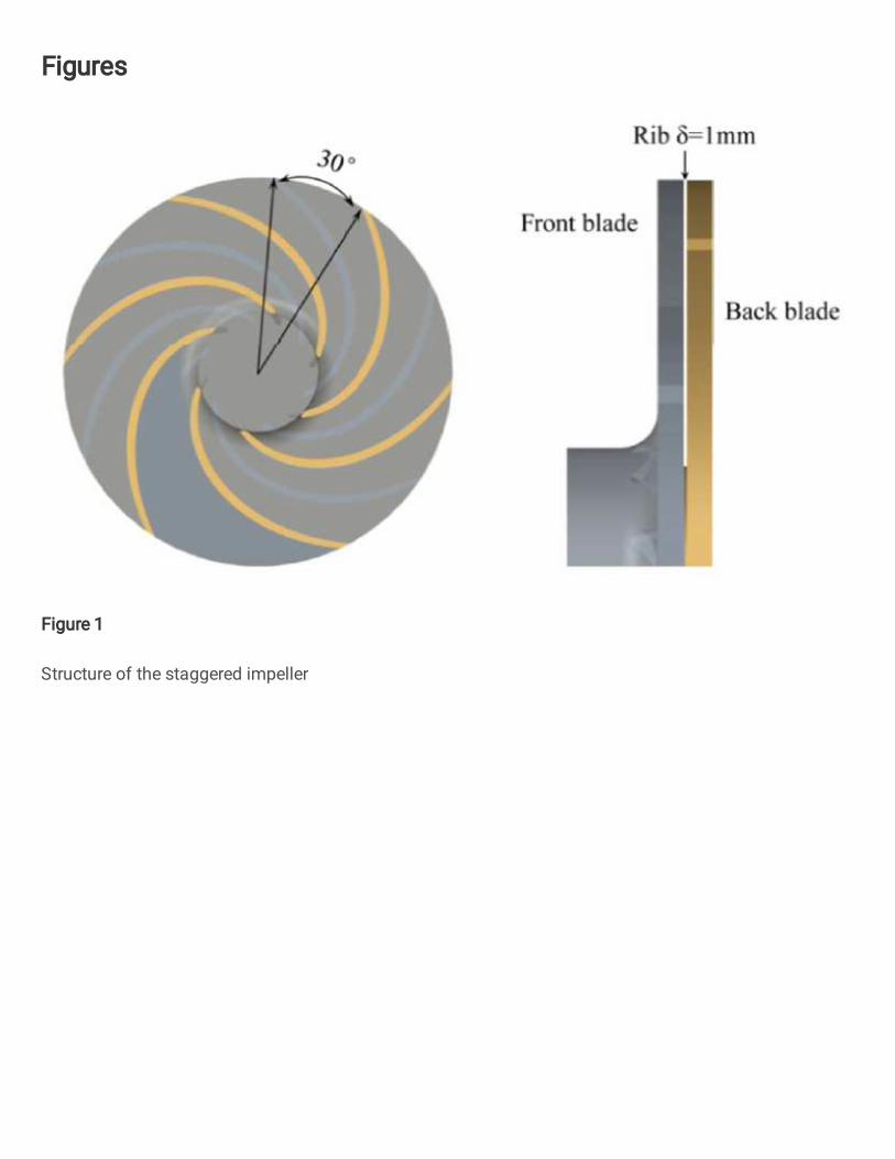
In this study, the model pump with two dimensional blade is used for investigation. Some basic parameters of the model pump are presented in table.1. During the pump design, the original impeller includes six blades. For the proposed staggered impeller, it could be divided into two parts by a rib in the middle of the impeller, namely the front blade and the back blade. The distance between the front and the back blade is δ=1mm. The intersection angle between the front and back blades is 30° as shown in fig.1. It means that for the original blade, it will be separated into two parts by the rib, then the back blade will be rotated by 30°. Finally, the staggered impeller will be formed, and the shape of the staggered impeller is the same with the original impeller. The phase difference will be generated between the front blade and the back blade when the fluid interacts with the tongue. The active outlet width of the staggered blade equals to the original impeller, namely the cross section area of the staggered impeller does not change. Finally, the influence of the rib on the flow capacity could be eliminated.
1.2 Mesh generation
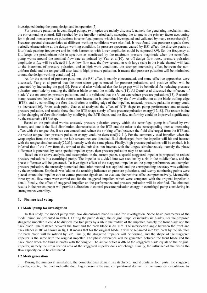
During the numerical simulation, the computational domain is established, and it contains four parts, the staggered impeller, volute, inlet duct and outlet duct. Fig.2 presents the used computational domain for the numerical calculation. As
fmtimmAt
for the model more easily tothe staggered n the reasona
mesh grid is 1million grids aAt the design that with the c
pump, the struo control and gimpeller. Obv
able range[24,21.1. Finally, 5 are generated working cond
current mesh g
PPRS
BImImVOBBORP
uctured mesh generate fromviously, the gr25]. For the immillion structfor the calcul
dition, the pregrids, the typic
T
ParametersPump flow ratPump head HdRotation speedSpecific speed
Blade number mpeller suctiompeller exit d
Volute exit diaOutlet width oBlade exit angBlade wrap anOutlet width oRib width δ Peripheral spe
Fig.2 C
grids are cream comparison wrid around thempeller, the htured grids arlated computaedicted y+ valcal flow struct
Table.1 Param
s e Qd
d d nd d 3.65
s dn n
Z on diameter Ddiameter D2 ameter D4 f the original
gle β2 ngle ϕ f the staggere
ed at the impe
Fig.1 Structur
Computational
3
ated by the ICwith the unstr
e solid wall ofheight of first re created for ational domainlue on the blatures could be
meters used for
0.75/d dQ H
D1
impeller b2
ed impeller b2
eller exit u2
ure of the stagg
l domain estab
CEM software.ructured gridsf the blade is elayer grid is the impeller an. Fig.4 show
ade wall from e resolved prec
r the current p
gered impeller
blished for cal
. The boundar. Fig.3 shows encrypted to gset as 0.1mm,and 4 million
ws the y+ distrthe steady re
cisely.
pump
Value 55 m3/h 20 m 1450 r/min69
6 80 mm 260 mm 80 mm 17 mm 30° 115° 18mm 1mm 19.7 m/s
r
culation
ry layer near t the generatedguarantee the , and the growfor the volute
ribution at theesult reaches 5
n
he solid wall d mesh grids oy+ value to b
wth ratio of the, and about 1e blade surfac5. It is believe
is of be he 11 e.
ed
1
TaptsbsMvs
t
1.3 Numerica
During thThe inlet and and outflow cpump flow ratthe relative msimulation, allbetween two cspatial discretMeanwhile, fovalue 3.0×10⁻⁵
set value. To obtain
transient calcu
al method
he steady numoutlet ducts a
conditions. Mete. At the pum
motion betweel solid surfacecomputationaltization, and or the coupling5 is set as the c
n influence oulation is con
Fi
Fig.4 Valu
merical simulatare prolonged eanwhile, at t
mp outlet, the pen the volutees of the compl domains, thefirst upwind
g of the pressconvergent sta
f the staggerenducted by th
Fig.5 Twen
ig.3 Mesh grid
es of y+ on th
tion, the SST kto at least thr
the inlet, the pressure outle
e and the impputational dome interface is a
scheme is cure and velocandard, and th
ed impeller ohe LES meth
nty points arou
4
ds of the used
he blade surfac
k-ω turbulent ree times of tvelocity boun
et condition wpeller, the mmain were regapplied. The lconducted to city, the SIMPhe pump perfo
on unsteady phod. The Sm
und the impell
staggered bla
ce at the desig
model was cothe pump suctndary conditio
with a constantmoving referen
garded as the least square cedispose the
PLE scheme isormance keeps
pressure pulsamagorinsky-Lil
ler exit during
ade
gn flow rate
onducted to obtion diameter on is given, wt value p=1.0×nce frame appnon-slip wallell method waspatial discre
s used during ts unchanged w
ations at variolly (SM) mod
g calculation
btain the pumto achieve th
which is calcu×105Pa is useproach is usel. To couple thas used to soletization durithe calculatio
when the resid
ous working del is adopte
p performanche stable inflowulated from thd. To deal wited. During thhe data transfeve the gradiening simulationn. The residua
dual reaches th
conditions, thed to close th
e. w he th he fer nt n. al he
he he

gampbmsppmFc
2
2
pesotfsciose
2
governing equapproach, it cmotion betweparameter duribe analyzed amethod is applstep to ensurepulsations of pressure signamonitoring poFinally, pressucharacteristics
2. Results
2.1 Comparis
The follo
Here, watPump pe
performance iexperimental dso in the curroriginal pumpthe flow rate dfront wear rinseen in fig.2. contributes to mprovement
observed fromsignificant. Theffect on the p
2.2 Effect of
Pressure
uation, and thecan be found een the voluteing unsteady s
and obtained lied to treat the the simulatithe model pu
als as presenteoint. During cure signals in s at various wo
and discus
son of pump p
owing equation
ter density ρ ierformance cois predicted data of the orient research,
p head coinciddeviates to 0.8
ng is the mainFrom compathe improvemis about 3%.
m the pump he difference pump performa
the staggered
coefficient is
e correspondinin the publish
e and impellesimulation, what every impe
he momentumion is fully coump, twenty ed in fig.5. Thcalculation, m
the last ten imorking conditi
ssions
performance
ns are used to
is 1000kg/m3. omparison beby SST k-ω iginal impellepump perform
des well with 8 and 1.2ФN, reason accouarison betweement of pump
At off-designefficiency, it is lower thanance will be g
d impeller on
used for inves
ng accuracy ihed research[er is solved bhich is set as Δeller rotating
m discretizationonverged. To points from Phe start angle
more than 30 impeller revolions.
obtain the no
tween the orturbulent mo
er[17]. For themance withinthe experimenthe numerical
unting for the en the originaperformance
n flow rates 0is found tha
n 1% at variogenerated, esp
Fig.6 Pum
n unsteady pr
stigation as ca
5
is validated by[26]. For the by the movinΔt=1.15×10⁻⁴sdegree. As f
n. During calcachieve influ
P1 to P20 are at point P1 iimpeller cyclelutions are use
on-dimensiona
2
2 2
= d
N
Q
u R
2
2
= d
N
gH
u
riginal and stodel. Meanwe general pumn 0.6-1.2ФN isntal data. At l error is lowecalculation e
al and stagge. For the mod0.8ФN and 1.
at the effect oous flow ratesecially for the
mp performan
ressure pulsat
alculated in Eq
y Poas et al[2unsteady calc
ng mesh apprs[27,28]. Namfor the LES mculation, the muence of the re placed arouis defined as es are simulated for the FF
al pump param
aggered impewhile, the calcmp, it will opers concerned. F1.0ФN, the nu
er than 4%. It error, which isered pumps, idel pump head.2ФN, incremeof staggered s. Finally, by e pump head.
nce compariso
tions
q.(3).
6]. As for theculation of thoach. The tim
mely, the pressmethod, the bmaximum 60 it
staggered impund the impezero, which ited to gain thT processing
meters[29,30].
ellers is first culation uncerate around thFrom comparumerical erroris inferred th
s not considerit is evident d under the deents are 2.3%impeller on applying the
on
e governing eqhe model pumme step is thsure value andbounded centriterations are s
mpeller on unseller exit to oincreases withhe periodic prto analyze pr
shown in figertainty is vahe design workrison, it is obr reaches abou
hat the fluid lered during thethat the stag
esign working% and 3.6% re
the pump effstaggered bla
quation of LEmp, the relativhe most cruciad flow field wiral differencinset for one timsteady pressurobtain unsteadh 18° for everressure signalressure spectra
(1
(2
g.6. The pumalidated by thking conditionserved that thut 1.3%. Whe
eaking from the calculation aggered impelleg condition, thespectively. A
fficiency is noade, significan
ES ve al ill ng me re dy ry ls. al
1)
2)
mp he n, he en he as er he As ot nt
ascrpcircctisw
ufF
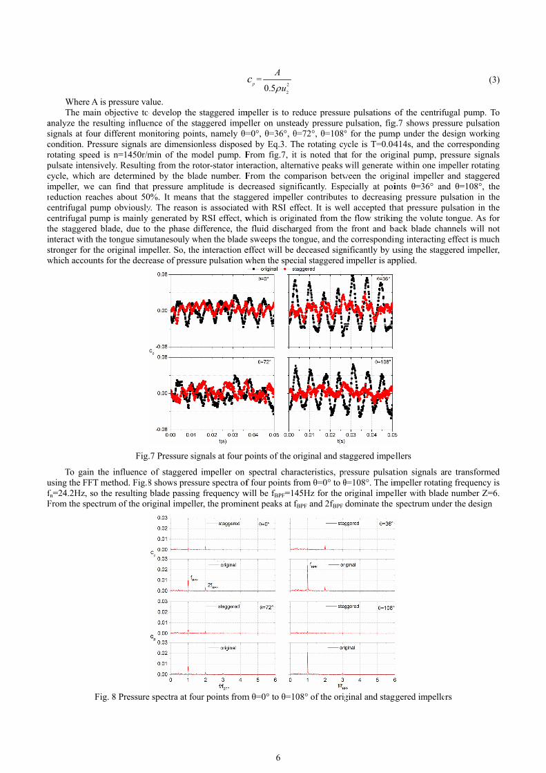
Where A The main
analyze the resignals at fourcondition. Prerotating speedpulsate intensicycle, which mpeller, we
reduction reaccentrifugal pucentrifugal puthe staggered nteract with th
stronger for thwhich account
To gain tusing the FFT fn=24.2Hz, so From the spec
F
is pressure van objective toesulting influer different mo
essure signals d is n=1450r/mively. Resultinare determinecan find thatches about 50ump obviouslyump is mainly
blade, due tohe tongue simhe original imts for the decr
Fig
the influence method. Fig.8the resulting trum of the or
Fig. 8 Pressure
alue. o develop the ence of the stonitoring poinare dimensio
min of the mng from the roed by the blat pressure am0%. It means y. The reason generated by
o the phase dmutanesouly wmpeller. So, therease of pressu
.7 Pressure sig
of staggered 8 shows pressblade passing
riginal impelle
e spectra at fou
staggered imaggered impe
nts, namely θ=onless disposemodel pump. Fotor-stator inteade number. F
mplitude is dethat the stag
is associatedy RSI effect, wdifference, thewhen the bladee interaction eure pulsation w
gnals at four p
impeller on sure spectra ofg frequency wer, the promin
ur points from
6
2
2
=0.5p
A
uc
mpeller is to reeller on unstea=0°, θ=36°, θed by Eq.3. ThFrom fig.7, iteraction, alterFrom the comecreased signiggered impelld with RSI efwhich is origie fluid dischare sweeps the toeffect will be when the spec
points of the o
spectral charf four points f
will be fBPF=14nent peaks at f
m θ=0° to θ=10
educe pressurady pressure
θ=72°, θ=108°he rotating cyt is noted thatrnative peaks wmparison betwificantly. Espeer contributes
ffect. It is weinated from thrged from theongue, and thedeceased sign
cial staggered
original and st
racteristics, prfrom θ=0° to θ45Hz for the ofBPF and 2fBPF
08° of the orig
re pulsations opulsation, fig
° for the pumycle is T=0.04t for the origwill generate
ween the origecially at pois to decreasinll accepted th
he flow strikine front and bae correspondinnificantly by uimpeller is ap
aggered impe
ressure pulsatθ=108°. The imoriginal impeldominate the
ginal and stag
of the centrifg.7 shows pre
mp under the d414s, and the
ginal pump, pwithin one im
ginal impeller ints θ=36° anng pressure phat pressure png the volute ack blade chang interactingusing the stagpplied.
ellers
tion signals ampeller rotatinller with bladspectrum und
ggered impelle
(3
fugal pump. Tssure pulsatiodesign workin
correspondinressure signa
mpeller rotatinand staggere
nd θ=108°, thpulsation in thpulsation in th
tongue. As foannels will nog effect is mucgered impelle
are transformeng frequency
de number Z=6der the design
ers
3)
To on ng ng als ng ed he he he or ot ch er,
ed is 6.

wgfanpci uspaabtdeaa
gFirtd
working condgenerated. Frofrequency is oare 89%, 94%nearly identicapressure pulsacomponent atnteraction by From fig
under the desishows comparpump, due to alternatively oamplitudes areblade is adoptetwenty points decrease is Δceffect on the around the imalleviated sign
F
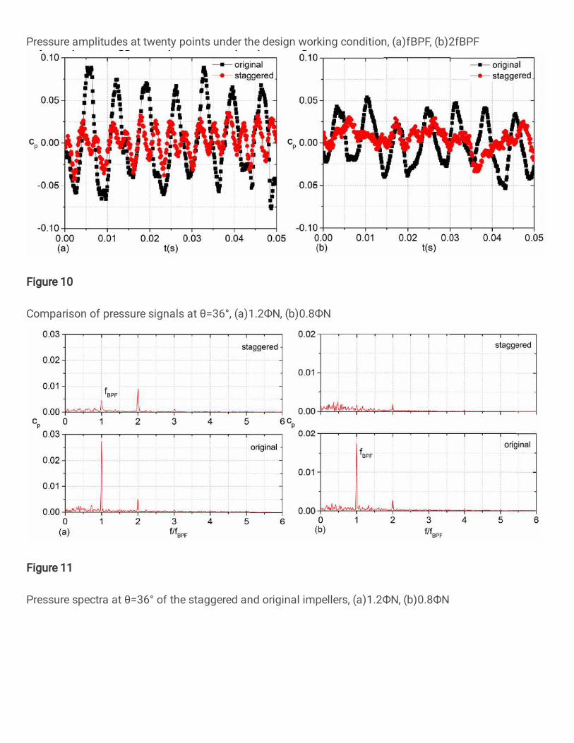
Centrifuggain the influeFig.10 presentt is notable th
reduction reacthe low workindecreased by t
ition. For theom comparisoobviously decr
%, 57% and 9al at 2fBPF. Fination of the cut 2fBPF is almproposing the.7 and fig.8, iign working crison of pressthe intense rooccur. For the almost equaed, pressure ais cp=0.0138
cp=89% by us2fBPF. As for
mpeller exit, nificantly as m
Fig.9 Pressure
gal pumps somence of staggts pressure puhat pressure pches about 50ng condition. the special sta
F
staggered imon of pressurereased at all t4% respective
nally, it is provurrent model
most unaffectee staggered blit is concludecondition. To sure pulsationotor-stator intehe staggered al, especially amplitudes at a84 for the orising the staggthe averaged
it is concludmanifested by t
e amplitudes a
metimes work ered impeller lsation signals
pulsation mag%. From fig.From fig.7 an
aggered impell
Fig.10 Compa
mpeller, similae spectrum, it the concernedely. Meanwhived that the sppump. The a
ed. The obtaade. d that for theanalyze the in
n amplitudes aeraction, presimpeller, sucfor the pointsall the twenty iginal impellegered impellerd values, the ded that by inthe decrease o
at twenty poin
at the off-deson reducing
s at point θ=3nitude of the 10(b), the stagnd fig.10, it isler for the pum
arison of press
7
ar phenomenois validated t
d monitoring pile, pressure apecial designeaveraged reduained results
e four points, nfluence of stat fBPF and 2f
ssure amplitudch phenomens θ>72°. As o
y monitoring per and cp=0.0r. From fig.9(difference is ntroducing thof pressure am
nts under the d
sign flow ratespressure puls6° with the pustaggered imggered impell
s concluded thmp working w
sure signals at
on is observedthat at 1.0ФNpoints. For poamplitudes ofed staggered imuction of the f
coincide with
pressure pulstaggered impefBPF for the cdes exhibit a mon is not obobserved at fB
points will be 001452 for th(b), it is founabout 6%. Fr
he staggered mplitude at fBP
design working
s, especially wsations when ump operating
mpeller is also ler also contrihat pressure puwithin 0.8-1.2Ф
t θ=36°, (a)1.2
d, namely, the, pressure am
oints θ=0° to f the original mpeller has a four points is h the assump
ation amplitudeller on the otoncerned twemodulated pat
bvious, and aBPF, it is evidreduced obvioe staggered im
nd that the starom comparisimpeller, rotoF.
g condition, (a
within 0.8-1.2Фthe pump wog under 1.2ФNlower than th
ibutes to decrulsation energФN.
2ФN, (b)0.8ФN
e peaks at fBPmplitude at the
θ=108°, the fand staggereddistinct effecabout 80%.
ption to redu
udes are decrether monitorinenty points. Fattern, and peaat different pdent that whenously. The aveimpeller. The aggered impeson of all theor-stator inter
a)fBPF, (b)2fBP
ФN. So, it is aorks at off-desN and 0.8ФN. Fhe original imreasing pressugy of the pump
N
F and 2fBPF are blade passinfinal reductiond impellers art on decreasinMeanwhile thce rotor stato
ased obviouslng points, fig.
For the originaaks and valleyoints, pressurn the staggereeraged value ocorrespondin
ller has a little twenty poinraction will b
PF
also essential tsign flow rateFrom fig.10(a
mpeller, and thure pulsation ap could also b
re ng ns re ng he or
ly .9 al ys re ed of ng le
nts be
to es. a), he at be

isaFi
ooo1c1cfepepm
2
Fpa
Fig.11 shs evident tha
spectrum at 1and the reductFrom the abovnteraction wh
To validaoff-design woroperating undeobvious in fig1.2ФN, pressurcp=0.0148 for 1.2ФN. When cp=0.0113 andfig.12, when texit are reducpublished reseeffect is not aspromising techmanufacturing
2.3 Typical fl
As for tFurthermore, iplanes are seleand back blade
hows pressure at distinct pea.2ФN. Compation is more tve analysis, it
hen the pump o
Fig.11 Press
ate the effectivrking conditioer 1.2ФN and
g.12(b) with thre amplitudesthe original ithe pump ope
d cp=0.00115 rthe staggered ced significanearches, somes significant ahnique to alle
g.
Fig
flow structure
the staggeredit is also impoected for invees as seen in f
spectra at theaks at the blaared with the than 80%. Tht is proved thoperates at va
sure spectra at
ve influence oons, fig.12 sh0.8ФN. From he pump opers at twenty poimpeller and cerates at 0.8Фrespectively, aimpeller is prtly, and the a
e approaches was the staggereviate pressur
.12 Pressure a
es within the
d impeller, poortant to obtaiestigation, namfig.13. As for t
e monitoring pade passing froriginal impe
he same phenohat the specialarious working
t θ=36° of the
of staggered imows pressurefig.12(a), the
rating at 0.8Фints are decrecp=0.0032 for
ФN, the averagand the decreroposed, pressaveraged reduwere investiged impeller in
re pulsation d
amplitudes of
blade channe
ositive effect in the effect omely the planethe original im
8
point θ=36° ofrequency fBPFeller, pressureomenon is alsl proposed stag conditions.
staggered and
mpeller on thamplitudes atpressure amp
ФN due to the eased by the sr the staggeredged pressure cement by usinsure amplitud
uction is moregated to decren the current p
during the low
the twenty po
el
will be genof staggered imes Section1 a
mpeller, the sa
f the staggeredand 2fBPF ca
e pulsation amso observed waggered impe
d original imp
e twenty mont fBPF for all t
plitude shows evident flow taggered imped impeller. Fincoefficients fog the staggere
des at the cone than 80% foease pressure paper. We bel
w noise pump
oints at fBPF, (a
nerated considmpeller on the
and Section2, ame relative p
d and original n be identifie
mplitude at fBPwhen the modller contribute
pellers, (a)1.2Ф
nitoring pointsthe calculated a descending separation at eller. The avenally, the redur the original ed impeller iscerned twentyor the three cpulsations in lieve that the design consi
a)1.2ФN, (b)0.
dering the une internal flowwhich locate ositions are al
l impellers. Fred and capturPF is alleviatedel pump opetes to decreasi
ФN, (b)0.8ФN
s when the pud twenty point
trend at 1.2Фlow working
eraged pressuruction reacheand staggere
s about 90%. Fy points arouncalculated flowpumps[31,32staggered imp
idering the fe
.8ФN
unsteady pressw distributionat the mid-sp
lso used for co
rom fig.11(a), red in pressurd significantlyrates at 0.8ФNing rotor-stato
ump operates ats for the pum
ФN, which is noconditions. A
re coefficient s about 80% ad impellers arFrom fig.9 annd the impellew rates. In th
2], however thpeller is a verasibility for i
sure pulsation. Here, two cu
pan of the fronomparison.
it re y, N. or
at mp ot At is at re nd er he he ry ts
n. ut nt

pgsFp
actmmgtio
pbtwico
Fig.14 prpressure distrigradually. At staggered impFinally, fluid phenomenon i
Fig.15 prat Section1, ancorrespondingthe staggered move in the frminimize the generated for the flow capacmpellers, it is
of the impellerTo furthe
presented in fiblade surface, the staggered which occupympeller. Due
caused aroundobserved for th
resents static ibutions are sithe Section2,eller. It is infeat the blade
is also reflecte
resents the relan evident low
g scale is reduimpeller as chront region of
low relative the staggeredcity reduction
s concluded thr even for the er analyze thfig.16 for the
especially onimpeller. Aro
y the blade to to the fluid s
d the blade lhe two impell
Fig
pressure distrimilar, especia, small differ
ferred that the inlet is acce
ed on the inter
Fig.14 Sta
ative velocity w velocity areuced comparedharacterized bf the impeller,
velocity regd impeller, andn in the back hat the rib with
low specific se influence otwo impellers
n the blade sucound the blade
blade channetriking the ribleading edge.lers.
.13 Two cut p
ributions of thally on the Seence is obsergenerating relerated for thrnal relative ve
atic pressure d
distributions ea is generatedd with the ori
by the high relwhich will caion around thd the low veloblade channe
hin the impellespeed impelleof staggered is. On Sectionction side for te leading edgel around the b, high turbule For vorticity
9
planes selected
the original anection1. Fromrved at the bleason is relatehe staggered elocity fields
distributions o
on Section1 ad around the iginal impellerlative velocityause the high he blade preocity region oel. From the rer will affect t
er within two dimpeller on t1, it is observthe two impel
ge, vortical strleading edge
ent flow will y distribution
d for investiga
nd staggered m the blade inllade inlet, andd to the blockblade resultinin fig.15.
n Section1 an
and Section2 ablade pressurr. At the blad
y. It means thavelocity sheessure side. A
on the blade pelative velocithe flow capadimensional bthe internal fved that high llers. On Sectiructures with e. For such phbe developed
ns towards th
ation
impellers on let to the outld low pressurking effect of ng in the low
nd Section2
at the design wre side of the e suction sideat by using thet generating o
At Section2, apressure side ity distributioncities in the frlade.
flow structurevorticity sheeion2, significahigh vorticity
henomenon, it. Finally, cohe
he blade outle
two sectionslet, pressure m
ure area is genthe existing r
w pressure reg
working condstaggered im
e, the fluid is e rib, some fluon the blade suan opposite pis increased, ans of staggereront and back
e, vorticity diets are developant difference y magnitudes t is caused by
herent flow stret, no eviden
s. As observedmagnitude risenerated for thrib on the fluidgion, and suc
dition. As notempeller, and th
accelerated fouid is forced tuction side anphenomenon and it indicateed and originablade channe
istributions arped around this observed foare developed
y the rib in thructures will bnt difference
d, es he d. ch
ed he or to nd is es al ls
re he or d, he be is

3
scoa
apwewf
u
3 Discuss
How to rstability durincontrol and reoriginated fromalleviating the
For the Rand the volutepressure pulsawill be reduceenergy of the will be generafinally, pressur
To validaused to divide
Fig.
sion
reduce unsteadng operation[3educe the higm the intense
e strong RSI efRSI effect, it ise tongue for thation amplituded obviously fluid acting oated. Then, thre pulsation amate the above e the impeller
Fig.15 Rela
.16 Vorticity d
dy pressure p33]. Such toph pressure pue rotor-stator ffect. s determined bhe single stagede[36-39]. Suby increasing
on the tongue.he fluid strikimplitude coulassumption, tr into two pa
ative velocity
distributions o
pulsations in cpic is discussulsations[34,3interaction. S
by the interacte centrifugal pch opinion is
g the rotor-sta. So, it is assuing energy beld be decreasethe staggered arts. The num
10
distributions
on Section1 an
centrifugal pused by many 5]. As for th
So, pressure p
ting effect betpump. It mean
validated in ator gap. The umed that by etween the flued significantl
impeller is dmerical simula
on Section1 a
nd Section2 of
mps is cruciaresearchers, e unsteady prpulsation amp
tween the highs that the strikthe publishedreason is assousing the stag
uid from the by.
designed and iation approach
and Section2
f the two impe
al to the pumpand various aressure pulsatplitude could
h speed fluid dking energy isd paper, and pociated with tggered impellblade with th
investigated inh is applied t
ellers
p design to enapproaches artions in pumpbe reduced s
discharged fros crucial for thpressure pulsathe reduction ler, and the ph
he tongue will
n the present to gain the in
nsure the pumre proposed tps, it is mainlsignificantly b
om the impellehe final resulteation amplitud
of the strikinhase differencl be alleviated
paper. A rib nfluence of th
mp to ly by
er ed de ng ce d,
is he
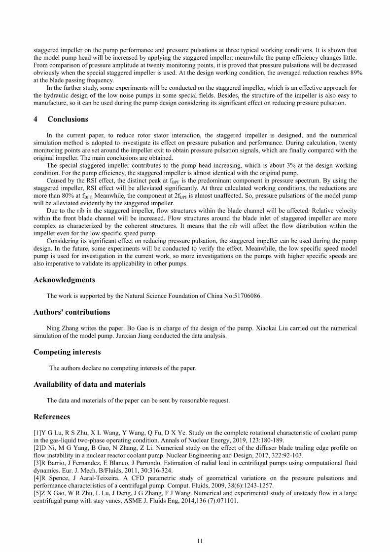
11
staggered impeller on the pump performance and pressure pulsations at three typical working conditions. It is shown that the model pump head will be increased by applying the staggered impeller, meanwhile the pump efficiency changes little. From comparison of pressure amplitude at twenty monitoring points, it is proved that pressure pulsations will be decreased obviously when the special staggered impeller is used. At the design working condition, the averaged reduction reaches 89% at the blade passing frequency.
In the further study, some experiments will be conducted on the staggered impeller, which is an effective approach for the hydraulic design of the low noise pumps in some special fields. Besides, the structure of the impeller is also easy to manufacture, so it can be used during the pump design considering its significant effect on reducing pressure pulsation.
4 Conclusions
In the current paper, to reduce rotor stator interaction, the staggered impeller is designed, and the numerical simulation method is adopted to investigate its effect on pressure pulsation and performance. During calculation, twenty monitoring points are set around the impeller exit to obtain pressure pulsation signals, which are finally compared with the original impeller. The main conclusions are obtained.
The special staggered impeller contributes to the pump head increasing, which is about 3% at the design working condition. For the pump efficiency, the staggered impeller is almost identical with the original pump.
Caused by the RSI effect, the distinct peak at fBPF is the predominant component in pressure spectrum. By using the staggered impeller, RSI effect will be alleviated significantly. At three calculated working conditions, the reductions are more than 80% at fBPF. Meanwhile, the component at 2fBPF is almost unaffected. So, pressure pulsations of the model pump will be alleviated evidently by the staggered impeller.
Due to the rib in the staggered impeller, flow structures within the blade channel will be affected. Relative velocity within the front blade channel will be increased. Flow structures around the blade inlet of staggered impeller are more complex as characterized by the coherent structures. It means that the rib will affect the flow distribution within the impeller even for the low specific speed pump.
Considering its significant effect on reducing pressure pulsation, the staggered impeller can be used during the pump design. In the future, some experiments will be conducted to verify the effect. Meanwhile, the low specific speed model pump is used for investigation in the current work, so more investigations on the pumps with higher specific speeds are also imperative to validate its applicability in other pumps.
Acknowledgments
The work is supported by the Natural Science Foundation of China No:51706086.
Authors' contributions
Ning Zhang writes the paper. Bo Gao is in charge of the design of the pump. Xiaokai Liu carried out the numerical simulation of the model pump. Junxian Jiang conducted the data analysis.
Competing interests
The authors declare no competing interests of the paper.
Availability of data and materials
The data and materials of the paper can be sent by reasonable request.
References
[1]Y G Lu, R S Zhu, X L Wang, Y Wang, Q Fu, D X Ye. Study on the complete rotational characteristic of coolant pump in the gas-liquid two-phase operating condition. Annals of Nuclear Energy, 2019, 123:180-189. [2]D Ni, M G Yang, B Gao, N Zhang, Z Li. Numerical study on the effect of the diffuser blade trailing edge profile on flow instability in a nuclear reactor coolant pump. Nuclear Engineering and Design, 2017, 322:92-103. [3]R Barrio, J Fernandez, E Blanco, J Parrondo. Estimation of radial load in centrifugal pumps using computational fluid dynamics. Eur. J. Mech. B/Fluids, 2011, 30:316-324. [4]R Spence, J Aaral-Teixeira. A CFD parametric study of geometrical variations on the pressure pulsations and performance characteristics of a centrifugal pump. Comput. Fluids, 2009, 38(6):1243-1257. [5]Z X Gao, W R Zhu, L Lu, J Deng, J G Zhang, F J Wang. Numerical and experimental study of unsteady flow in a large centrifugal pump with stay vanes. ASME J. Fluids Eng, 2014,136 (7):071101.

12
[6]R Barrio, J Parrondo, E Blanco. Numerical analysis of the unsteady flow in the near-tongue region in a volute-type centrifugal Pump for different operating points. Comput. Fluids, 2010, 39 (5):859-870. [7]J F Zhang, D Appiah, F Zhang, S Q Yuan, Y D Gu, SN Asomani. Experimental and numerical investigations on pressure pulsation in a pump mode operation of a pump as turbine. Energy Sci Eng, 2019, 7:1264-1279. [8]Y Fu, J Yuan, S Yuan, G Pace, L D’Agostino, P Huang, X Li. Numerical and experimental analysis of flow phenomena in a centrifugal pump operating under low flow rates. ASME J. Fluids Eng,2015, 137(1):011102. [9]C G Rodriguez, E Egusquiza, I F Santos. Frequencies in the vibration induced by the rotor stator interaction in a centrifugal pump turbine. ASME J. Fluids Eng, 2007, 129:1428-1435. [10]Z F Yao, F J Wang, L X Qu, R F Xiao, C L He, M Wang. Experimental investigation of time-frequency characteristics of pressure fluctuations in a double suction centrifugal pump. ASME J. Fluids Eng, 2011, 133 (10):101303. [11]Pavesi G, Cavazzini G, Ardizzon G. Time–frequency characterization of the unsteady phenomena in a centrifugal pump. Int. J. Heat Fluid Flow, 2008, 29(5):1527-1540. [12]J L Parrondo-Gayo, J Gonzalez-Perez, J Fernandez-Francos. The effect of the operating point on the pressure fluctuations at the blade passage frequency in the volute of a centrifugal pump. ASME J. Fluids Eng, 2002, 124(3):784-790. [13]S S Yang, H L Liu, F Y Kong, B Xia, L W Tan. Effects of the radial gap between impeller tips and volute tongue influencing the performance and pressure pulsations of pump as turbine. ASME J. Fluids Eng, 2014, 136(5): 054501. [14]A Posa, A Lippolis. Effect of working conditions and diffuser setting angle on pressure fluctuations within a centrifugal pump. Int.J. Heat Fluid Flow, 2019, 75:44-60. [15]A M Al-Qutub, A E Khalifa, F A Al-Sulaiman. Exploring the effect of V-Shaped cut at blade exit of a double volute centrifugal pump. ASME Journal of Pressure Vessel Technology, 2012, 134:021301. [16]J Keller, E Blanco R Barrio, J Parrondo. PIV measurements of the unsteady flow structures in a volute centrifugal pump at a high flow rate. Exp. Fluid, 2014,10 (55):1820. [17]B Gao, N Zhang, Z Li, D Ni, M G Yang. Influence of the blade trailing edge profile on the performance and unsteady pressure pulsations in a low specific speed centrifugal pump. ASME J. Fluids Eng, 2016, 138(5):051106. [18]N Zhang, X K Liu, B Gao, X J Wang, B Xia. Effects of modifying the blade trailing edge profile on unsteady pressure pulsations and flow structures in a centrifugal pump. Int. J. Heat Fluid Flow, 2019, 75:227-238. [19]N Zhang, X Liu, B Gao, B Xia. DDES analysis of the unsteady wake flow and its evolution of a centrifugal pump. Renewable Energy, 2019, 141:570-582. [20]B Kye, K Parka, H Choia, M Lee, J Kim. Flow characteristics in a volute-type centrifugal pump using large eddy simulation. International Journal of Heat and Fluid Flow, 2018, 72:52-60. [21]N Zhang, J X Jiang, B Gao, X K Liu, D Ni. Numerical analysis of the vortical structure and its unsteady evolution of a centrifugal pump. Renewable Energy, 2020, 155:748-760. [22]J Pei, W J Wang, G Pavesi, M K Osman, F Meng. Experimental investigation of the nonlinear pressure fluctuations in a residual heat removal pump. Annals of Nuclear Energy, 2019, 131:63-79. [23]D Ni, N Zhang, B Gao, Z Li, M G Yang. Dynamic measurements on unsteady pressure pulsations and flow distributions in a nuclear reactor coolant pump. Energy, 2020, 198:117305. [24]A Posa, A Lippolis, E Balaras. Investigation of separation phenomena in a radial pump at reduced flow rate by large-eddy simulation. ASME J. Fluids Eng, 2016, 138 (12):121101. [25]N Zhang, J X Jiang, B Gao, X K Liu. DDES analysis of unsteady flow evolution and pressure pulsation at off-design condition of a centrifugal pump. Renewable Energy, 2020, 153:193-204. [26]A Posa, A Lippolis, R Verzicco, E Balaras. Large-Eddy simulations in mixed-flow pumps using an immersed-boundary method. Comput. Fluids, 2011, 47 (1):33-43. [27]W Jiang, G J Li, P F Liu, L Fu. Numerical investigation of influence of the clocking effect on the unsteady pressure fluctuations and radial forces in the centrifugal pump with vaned diffuser. Int. Commun. Heat Mass Tran, 2016, 71:164-171. [28]D Zhang, W Shi, B Bart van Esch, L Shi, M Dubuisson. Numerical and experimental investigation of tip leakage vortex trajectory and dynamics in anaxial flow pump. Comput. Fluids, 2015, 112:61-71. [29]N Zhang, B Gao, D Ni, X K Liu. Coherence analysis to detect unsteady rotating stall phenomenon based on pressure pulsation signals of a centrifugal pump. Mechanical Systems and Signal Processing, 2021, 148:107161. [30]N Zhang, F K Zheng, X K Liu, B Gao, G P Li. Unsteady flow fluctuations in a centrifugal pump measured by laser Doppler anemometry and pressure pulsation. Phys. Fluids, 2020, 32:125108. [31]D Z Wu, P Yan, X Chen, P Wu, S Yang. Effect of trailing-edge modification of a mixed-flow pump. ASME J. Fluids Eng, 2015, 138:101205. [32]K Wang, Z X Zhang, L L Jiang, H L Liu, Y Li. Effects of impeller trim on performance of two-stage self-priming centrifugal pump. Adv Mech Eng, 2017, 9(2):1-11. [33]W J Wang, J Pei, S Q Yuan, T Y Yin. Experimental investigation on clocking effect of vaned diffuser on performance characteristics and pressure pulsations in a centrifugal pump. Experimental Thermal and Fluid Science, 2018, 90: 286-298. [34]Q Q Li,S Y Li, P Wu, B Huang, D Z Wu. Investigation on reduction of pressure fluctuation for a double-suction centrifugal pump. Chinese Journal of Mechanical Engineering, 2021, 34(12):1-18.

13
[35]Y Tao, S Q Yuan, J R Liu, F Zhang. Influence of Cross-Sectional Flow Area of Annular Volute Casing on Transient Characteristics of Ceramic Centrifugal Pump. Chinese Journal of Mechanical Engineering, 2019, 32(4):1-13. [36]Y B. Liu, L Tan. Spatial-temporal evolution of tip leakage vortex in a mixed-flow pump with tip clearance. ASME J Fluids Eng, 2019, 141:081302. [37]Y B Liu, L Tan. Tip clearance on pressure fluctuation intensity and vortex characteristic of a mixed flow pump as turbine at pump mode. Renew Energy, 2018, 129:606-615. [38]A Posa, A Lippolis. A LES investigation of off-design performance of a centrifugal pump with variable-geometry diffuser. Int. J. Heat Fluid Flow, 2018, 70: 299314. [39]N Zhang, B Gao, Z Li, D Ni, Q Jiang. Unsteady flow structure and its evolution in a low specific speed centrifugal pump measured by PIV. Exp. Therm. Fluid Sci, 2018, 97:133-144.
Figures
Figure 1
Structure of the staggered impeller

Figure 2
Computational domain established for calculation
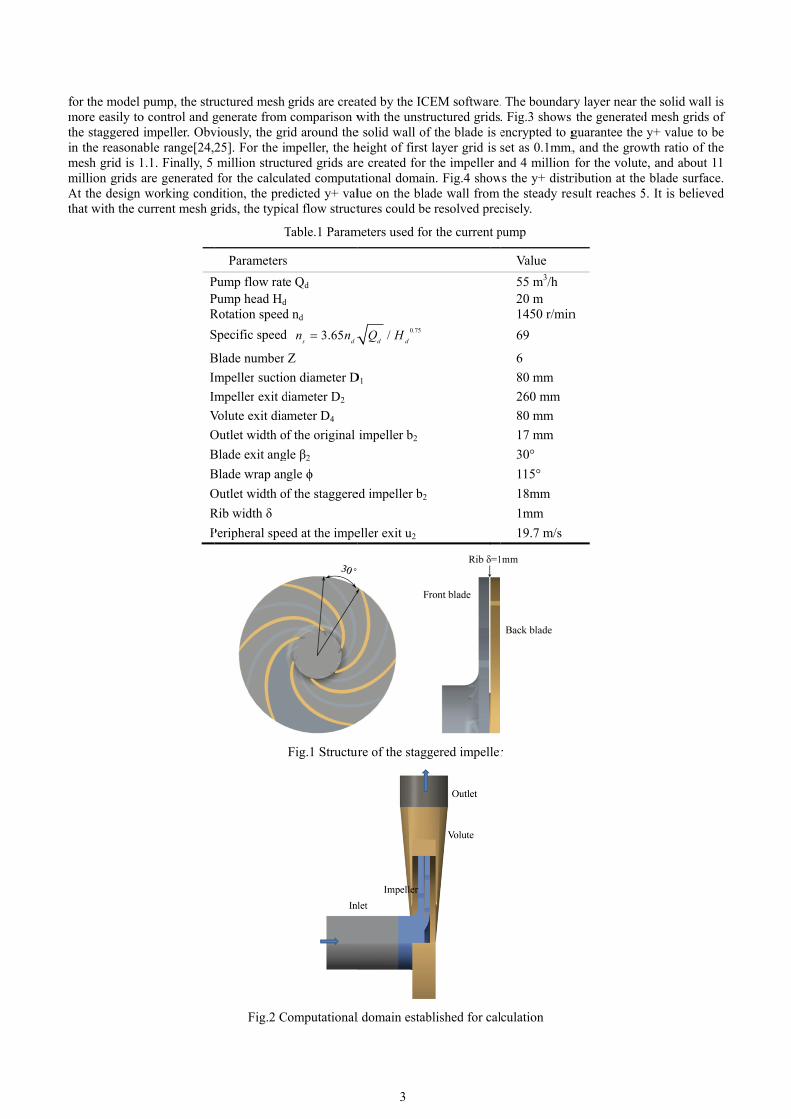
Figure 3

Mesh grids of the used staggered blade
Figure 4
Values of y+ on the blade surface at the design �ow rate

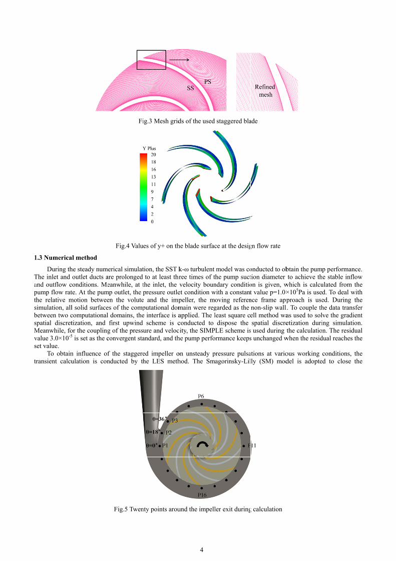
Figure 5
Twenty points around the impeller exit during calculation
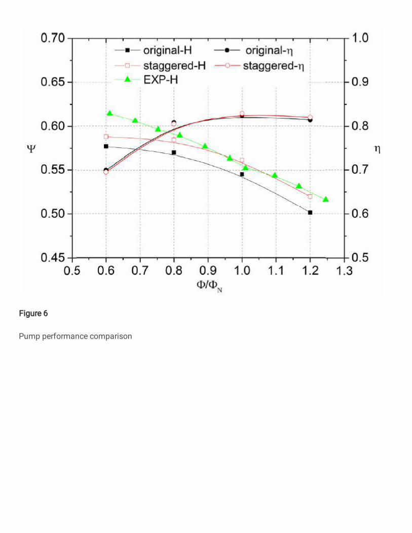
Figure 6
Pump performance comparison

Figure 7
Pressure signals at four points of the original and staggered impe llers

Figure 8
Pressure spectra at four points from θ=0° to θ=108° of the original and staggered impellers
Figure 9
Pressure amplitudes at twenty points under the design working condition, (a)fBPF, (b)2fBPF
Figure 10
Comparison of pressure signals at θ=36°, (a)1.2ФN, (b)0.8ФN
Figure 11
Pressure spectra at θ=36° of the staggered and original impellers, (a)1.2ФN, (b)0.8ФN
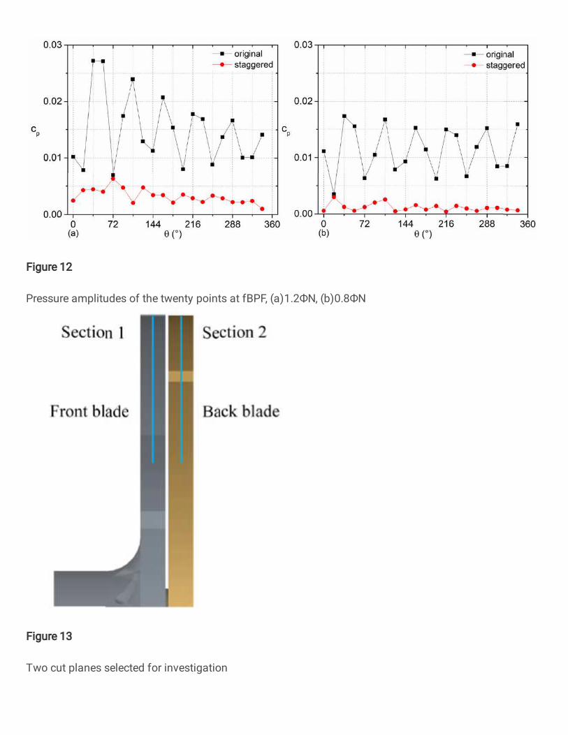
Figure 12
Pressure amplitudes of the twenty points at fBPF, (a)1.2ФN, (b)0.8ФN
Figure 13
Two cut planes selected for investigation

Figure 14
Static pressure distributions on Section1 and Section2

Figure 15
Relative velocity distributions on Section1 and Section2

Figure 16
Vorticity distributions on Section1 and Section2 of the two impellers