effect of surface coatings and exposure on …digital.lib.lehigh.edu/fritz/pdf/318_5.pdf · effect...
TRANSCRIPT

Bolted Connections
EFFECT OF SURFACE COATINGS
AND EXPOSURE ON SLIPBEHAVIOR OF BOLTED JOINTS
ENGJf\JEERfl'JCiLIBRARY
by
James H. LeeColin O'Connor
John W. Fisher
Fritz Engineering Laboratory Report 318.5

EFFECT OF SURFACE COATINGS AND EXPOSURE
ON SLIP BEHAVIOR OF BOLTED JOINTS
James H. Lee
Colin O'Connor
John W. Fisher
This work was carried out as part of the Large Bolted ConnectionsProject sponsored financially by the Pennsylvania Department ofHighways, the Department of Transportation - Bureau of PublicRoads, ond the Research Council on Riveted and Bolted StructuralJoints. Technical guidance is provided by the Research Councilon Riveted and Bolted Structural Joints.
Fritz Engineering Laboratory
Department of Civil Engineering
Lehigh University
Bethlehem, Pennsylvania
June 1968
Fritz Engineering Laboratory Report No. 318.5

1.
2.
3.
4.
5.
6.
7.
TABLE OF CONTENTS
ABSTRACT
ACKNOWLEDGMENTS
INTRODUCTION
PREVIOUS WORK
TESTING PROGRAM
3.1 Description of Specimens
3.2 Plate Properties
3.3 Calibration of Bolts
3.4 Fabrication and. Assembly of Joints
3.5 Instrumentation of Joints and Bolts
3.6 Testing Procedure
TEST RESULTS AND ANALYSIS
4.1 Slip Coefficient
402 Effect of Slotted Holes onSlip Behavior
4.3 Effect of Vinyl Wash Coatings onSlip Behavior
4.4 Effect of Rusting on Slip Behavior
4.5 Effect of Linseed Oil on Slip Behavior
SUMMARY AND CONCLUSIONS
TABLES AND FIGURES
REFERENCES
i
ii
1
4
5
5
6
7
8
9
9
11
11
12 '
12
15
16
17
19
32

ABSTRACT
Eighteen joints of A36 steel with 1 in. diameter A325
high strength. bolts were tested to investigate some effects of
surface' treatment on slip behavior.
All joints were initially blast cleaned. Three had
slotted holes. Three were exposed for 2, 6 and 12 months with
out protection before assembly and testing. Nine were'treated
with linseed oil or vinyl wash coatings and exposed to an in
dustrial environment for 2 months before testing. Three were
treated with vinyl wash coatings but were not exposed to the
outside environment.
Slotted holes reduced the slip coefficient from 0.65
to 0.49. Exposure without protection reduced the slip coefficient
from 0.65 to about 0.4. The slip coefficient with protective
coatings was reduced from about 0.28 to 0.26 after 2 months
exposure. This reduction is not significant.
ACKNOWLEDGMENTS
This study has been carried out as part of the research
project ttLarge Bolted Connections U being conduc,ted at Fritz En
gineering Laboratory, Departmertt of Civil Engineering, Lehigh
University.
The project was sponsored by the Pennsylvania Department
of Highways, the U. S. Department of Transportation - Bureau of
Public Roads, and the Research Council on Riveted and Bolted
Structural Joints. Technical guidance has been provided by the
Council through an advisory committee under the c~airmanship of
Mr. T. W. S~ilman.
The authors express their thanks to their co-workers
N. Yoshida and S. Desai and to Ken Harpel and his laboratory
'technicians for help with the testing. The manuscript was typed
by Shirley Labert and the photography and drawings done under
the supervision of Ric~ard Sopko.
ii

1. INTRODUCTION
In steel construction, it is common to paint faying
surfaces with a protective coating to prevent corrosion due to
exposure bef6re erection. These coatings are usually removed
at assembly, either by grinding or by dissolving with various
solvents. Red lead paint, which is commonly used, reduces the
slip coefficient considerably, and must be removed from joints
designed as friction-type joints. Vinyl wash and linseed oil
coatings are considered in this project as substitutes for red
lead and similar paints and have been left in place during as
sembly and testing. Joints without coatings have also been in
vestigated to see how rusting itself affects the performance of
a bolted j.oint.
The Steel Structures Painting Council Pretreatment
Specification SSPC-PT3-64 requires these coatings to be used
on cl~an steel free of rust and scale. 6 The coating material
must meet the specification MIL-P15328B. A dry film thickness
of 0.3 to 0.5 mil is required and the base metal should show
through the washcoat as evidenced by uneven coloring.
Not all states permit the specification MIL-P15328B.
The state of California still requires MIL-C15328A, but not any
later revision~ The only differences between MIL-C15328A and

MIL-P15328B are the. type of alcohol used, the viscosity of the
pigment, and the fineness of grind of the pigment. Under this
study, both materials are investigated.
The first test series consisted of three joints with
a vinyl wash coating conforming to MIL-C15328A. The spcimens
were blast cleaned, coated and then assembled, and stored inside
the laboratory prior to testing. However, in most field situa
tions, structural members are exposed to the atmosphere for. a
period before erection. In order to simulate this field expo
sure condition, a second test program was initiated.
Twelve blast cleaned joints were divided into four
series of three. Two of the series were treated with vinyl wash
coatings to MIL-C15328A and MIL-Pl5328B. A third series was
treated with linseed oil. These nine joints were exposed out
side the laboratory for a period of two ,months before assembly
to simulate the field condition. The fourth series was blast
cleaned and exposed without treatment for periods of two, six
and twelve months to investigate the effect of rusting on slip
behavior 0
Three joints with slotted holes were also tested in
this test program. These joints were tested previously with
clean mill scale faying surfaces. After testing, they were
-2-
blast cleaned and retested to see the effect of blast cleaning
on the slip coefficient. All three joints were stored inside
the laboratory prior to testing.
-3-

2. REVIEW OF PREVIOUS WORK
The University of Washington reported work by Brookhart,
Siddiqi and Vasarhelyi in 1966 on the effect of galvanizing and
other surface treatments on high tensile bolts and bolted joints. 2
Vinyl wash coating conforming t·o MIL-C15328A arid MIL-P15328B
were considered in the report. All plates were in the sand
blasted and degreased conditi~n before the' surface treatment was
applied. Joints were not exposed before testing. The bolts
were A325 black bolts. The average slip coefficient was 0.28.
Several tests have been undertaken at Lehigh University
on joints with slotted holes. 1 Tests on plates with mill scale
surfaces showed a reduction in slip coefficient of 33% due to
the use of slotted holes instead of the normal clearance round
holes. The loss of bolt tension with time was not greatly
affected.
-4-
3 • TEST PROGRAM
3.1 Description of Specimens
The test specimens for this study were double lap
joints with two lines of four bolts. The joints were fabricated
from 1 inch thick A36 plate and had the geometries shown in
Figures I and 2. The bolts were 1 inch diameter A325 bolts con
necting four plies of plates, at a pitch of 5-1/4 inches.
Fifteen joints had been tested previously with clean mill scale
surfaces. These joints were newly fabricated with blast cleaned
faying surfaces.
The eighteen joints were divided into six groups (See
"Table I). The first group of three joints were designated BOHI.
The faying surfaces were blast cleaned and "treated with vinyl
wash coating conforming to MIL-C15328A. The co?ting was applied
at least 20 hours after blast cleaning. The specimens were
stored inside the laboratory prior to testing.
The second group, designated SOH2, were not coated,
and were exposed to the humid industrial atmosphere of Bethlehem,
for periods of two months, six months and twelve months after
blast cleaning. They were then bolted up without wire brushing
or otherwise di·sturbing the rusted surfaces.
- 5-

Th~ third group, designated SOH3, were treated with
linseed oil after blast cleaning the surfaces. The fourth,
designated SOH4, were treated with vinyl wash coating conforming
to MIL-C15328A. The fifth group, designated SOH5, consisted of
new fabricated joints with blast cleaned surfaces and were
treated with vinyl wash coating conforming to MIL-P15328B. These
three groups, SOH3, SOH4, and SOH~ were exposed for two months
outside the laboratory, in the Bethlehem atmosphere, before
assembly and testing.
The sixth group, designated SSHl, were blast cleaned
joints with slotted holes parallel to the line of load as shown
in Figure 2.
3.2 Plate Properties
The A36 steel plates were ordered to minimum strength.
The plates were 28-1/2 inches wide and 34 feet long. Tensile
coupons were taken from a 2 foot section out from the middle of
each plate and were tested in a mechanical universal testing
machine. The testing speed was 0.025 inches pe'r minute until
strain hardening beg'an. The static yield load was obtained by
stopping the machine during yield and allowing the machine to
stabilize. When the coupon went into strain hardening, the
testing speed was increased to 0.3 inches per minute until th~
-6-

coupon failed. The load-strain curve for an 8 inch gage length
was plotted by automatic recorder for each coupon.
Three standard bar specimens were taken from each plate
used for test specimens. The mean static yield stress was 29.4
ksi with a standard deviation of 0.49 ksi. The mean tensile
strength was 61.2 ksi with a standard deviation of 2.9 ksi.
The percent elongation in 8·in. varied from 29% to 36 percent.
The reduction in area varied from 61% to 65 percent.
3.3 Calibration -of Bolts
One inch diameter A325 bolts were used to bolt up all
eighteen joints. Direct tension and torque tension calibrations
were performed on each lot of bolts. Details are given elsewhere. 3
Three bolts were chosen at random for each calibration. For the
direct tension calibration, the bolts were tested in a universal
testing machine, and the elongation of the bolts was measured
by C-frame extensometer. For the otrque tension calibration, a
Skidmore-Wilhelm calibrator was used. The average load-elongation
curve for three bolts was obtained and considered to be typical
of the general behavior of the whole lot.
All the bolts that were calibrated satisfied the mini
mum proof load and ultimate load requirements spe.cified by the
ASTM. Since the bolts were tested at the same grip as existed
-7-

in the joint, the load-elongation curves obtained from the torque
tension calibration tests could be used directly to determine the
tension in the bolts as installed in the joints.
3.4 Fabrication and Assembly
The test joints were fabricated by a local steel fab
ricator. The individual plates were flame cut to rough size and
then milled to the specified joint dimensions. The faying sur
faces were cleaned of loose mill scale and burrs. The four cor
ner holes were sub-drilled and reamed for alignment. The four'
remaining holes were then drilled through all four plies of steel
to the specified size while the plates were held in alignment by
steel pins in the corner holes.
The slotted holes were formed 'by drilling two adjacent
holes in the plate and removing the metal between them. All
coatings were applied by the fabricator following standard pro
cedures for field construction suggested in Reference 1.
Assembly and instrumentation of the joints were per
formed at the Fritz Engineering Laboratory. All ,bolts were
tightened by the turn-af-nut method. 6 Half turn was applied to
all bolts from snug position. The bolt tension was determined
by measuring the change in bolt length with the extensometer and
then determined the corresponding bolt tension from the torque
tension calibration curve.
-8-
3.5 Instrumentation of Joints
All the specimens were instrumented to record. their
performance during testing. Instruments were designed to record
slip and elongation of the joint. Two 0.0001 inch dials were
attached to tabs tack-weided to both sides of the main plate in
line with the first row of bolts. The tips of the gages rested
on a frame that was tack-welded to the lap plates in line with
the tabs. Thus, slip movement between the main and lap plates
was measured on one line and effects due to axial strains were
minimized.
Two 0.0001 inch dials were attached to tabs tack-welded
to both sides of the main plate one pitch length outside the
first row of bolts. Two steel bars were tack-welded on both
sides of the lap plate one pitch length outside the last row of
bolts. Wires were attached to the pointers of the dials and the
steel bars. The measured total joint elongation included elastic
"elongations over a 26-1/4 in. length as well as. any slip between
the faying surfaces.
3.6 Testing Procedure
All the joints were tested in a 800 kip universal
testing machine using flat wedge grips. Readings were taken at
-9-

zero load, and then at every 10 kips until slip was near. In
the slip range, loads were read every 5 kips or controlled by
the movement of the dial. Tests terminated when the bolts were
completely in bearing.
After testing, the joints w~re dismantled and examined.
Photographs were taken of any unusual disturbances of the con
tact surfaces.
-10-

4. TEST RESULTS AND ANALYSIS
4.1 Slip Coefficient
The slip coefficient is defined as K = PINT where K
is the slip coefficient, P the slip load, N the number of slip
planes, and T the total initial clamping force. The total clamp
ing force has been taken as the sum of all the bolt tensions.
For joints that had sudden and definite slip, slip
load can easily be defined as the highest load the joint can
resist before major slip.
For joints that had no definite major slip, the slip
load could only be arbitrarily defined. Two definitions were
used. in this report. The first definition was based on load vs.
elongation curve. The load that deviated from the straight
line or elastic portion was defined as the slip load and the
corresponding coefficient is referred to as Xl in this report.
The second definition was based on the load vs. slip
curve. The load that .corresponded to 0.02 inches total slip
movement was defined as the slip load and referred to by K2 in
this report. The sliP. coefficients of each of the joints are
summarized in Table II.
-11-

402 Effect of Slotted Holes on Slip Behavior
Three joints had slotted' holes in the enclosed plates,
with the slots placed parallel to the line of the load. These
joints had been tested previously with clean mill scale faying
surfaces. 1 A large amount of minor slip occurred before the
joint came completely into bearing. The slip coefficient de
creased from 0.30 for the control tests to 0.2. Inspecti~n of
the faying surfaces showed severe mill scale disturbances over
the entire face of the joint.
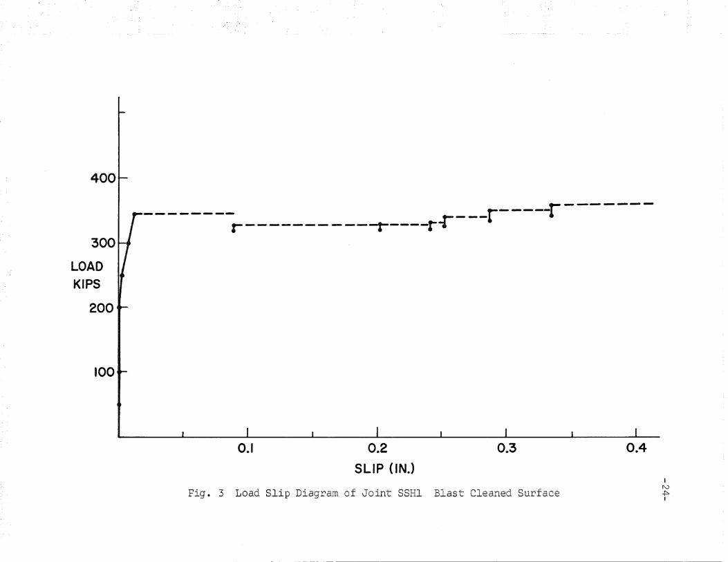
After testing, these joints were blast cleaned and re
tested. The slip behavior was similar to that of the clean mill
icale specimens as shown in Fig. 3, but with a reduced number
of minor slips before bearing. The slip coefficient decreased
from 0.67, the result for blast cleaned control· tests, to 0.49.
A graphical presentation of the test results is shown in Figure
4. For the blast cleaned specimens, the tested surfaces showed
severe disturbance and galling as shown in Figure 5.
4.3 Ef~ect of Vinyl Wash Coatings on Slip Behavior
Nine joints were tested with vinyl wash coatings under
this study. Three joints were coated according to MIL-C15328A
about 20 hours after blast cleaning. The joints were stored
inside the laboratory prior to testing. These joints had normal
hole clearance 1/16 in. bigger than the bolt diameters.
-12-

For the other six joints, SOH4 were coated .with vinyl
wash coating conforming to MIL-CIS328A and SOHS were coated with
vinyl wash coating conforming to MIL-PIS32SB. All six joints
were exposed outside the laboratory for two mODths before as
sembly to simulate field condition prior to erection. SOH4 had
oversize holes 5/16 in. bigger than the bolt diameter and SORS
had oversize holes 1/4 in. bigger than the bolt diameter.
Figure 6 shows a comparison of the behavior of joint,
SOHl, as originally tested with clean mill scale surfaces, and
then with a vinyl wash coating. In the first case, major slip
occurred around 300 kips followed by a large drop in load. A
few minor slips followed. For the vinyl wash coated specimens,
gradual slip occurred and the joint elongated under constant
load at slip. No drop of load nor violent noise occurred. It
is evident that the two tests gave approximately the same slip
load. The vinyl wash coating reduced the slip coefficient from
the blast cleane4 value to about the same as for the original
mill scale surfaces.
The test results are compared with tests by the Uni
versity 'of Washington2 as shown in Figure 7. The average slip
coefficient reported by the University of-Washington for vinyl
wash conforming to MIL-P15328B_ was 0.28, and for vinyl wash
-13-

conforming to MIL-C15328A was 0.27. The result obtained in the
present program for vinyl wash MIL-C15328A without exposure was
0.30. These figures are comparable.
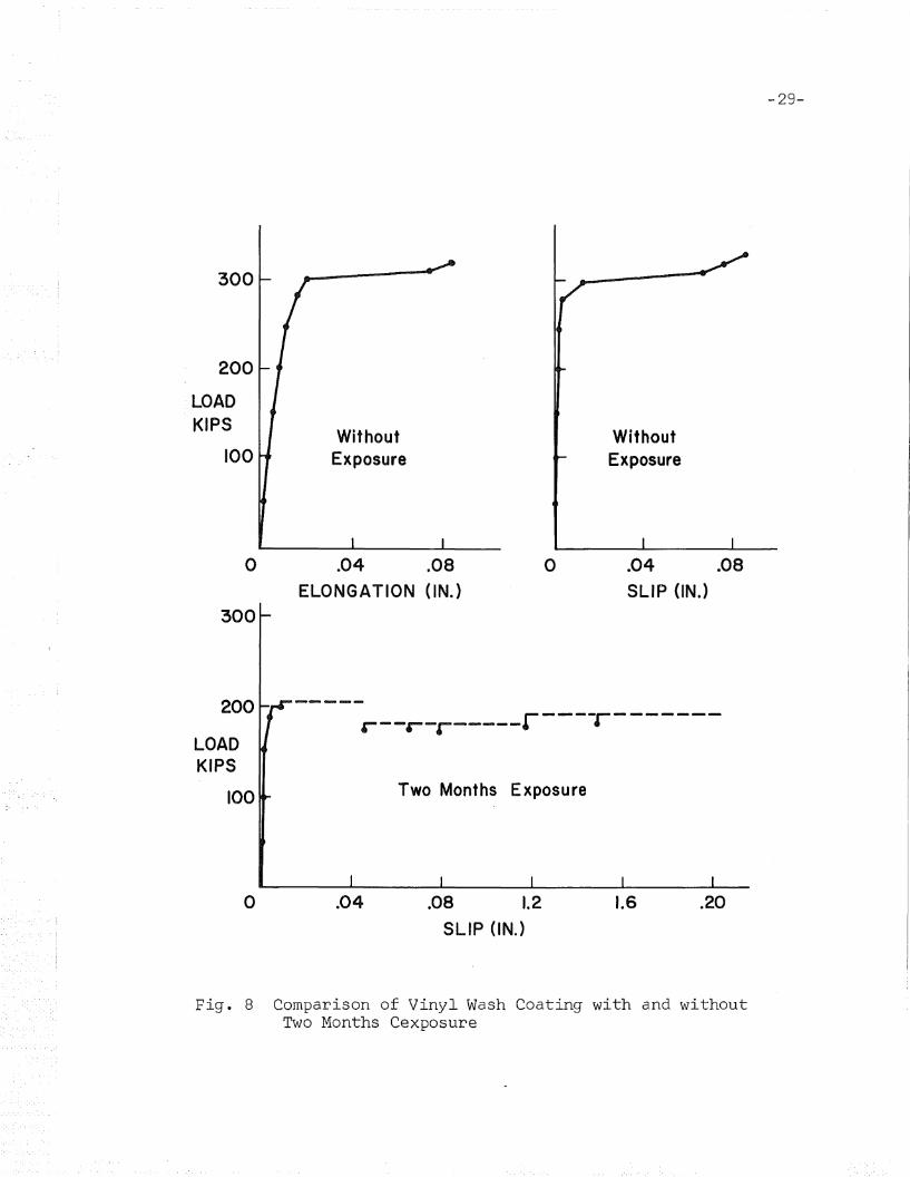
SOH4 had a vinyl wash coating with two months expo
sure outside the laboratory. Close inspection showed no rust
ing of the coated areas, and indicated that the vinyl wash
coating gave adequate protection. A comparison with the joints
without exposure is shown in Figure 8. Sudden slip occurred
for the joints with two months exposure. It was followed by
a large drop of load with violent movement of the slip dials.
The average slip coefficient of 0.29 for the joints without ex
posure is slightly higher than the figure of 0'.26 for the joints
with exposure. However, the exposed joints (SOH4) had 5/16 in.
oversize holes. It has been shown previously, that this size
hole causes a reduction in slip coeffic~ent ~n the order of
17 percent. 1 Therefore, it is concluded that there is no sig
nificant effect on slip coefficient of two months exposure.
All coatings were applied by a local fabricator fol
lowing standard procedures for field construction. The average
thickness of coating was 0.33 y ·.03 mils. This was obtained by
measuring the total plate thickness with a micrometer before and
after coating was removed with a solvent. An increased coating
thickness would probably reduce the slip resistance as all sur
face irregularities would be covered.
-14-

SOHS were new fabricated joints with vinyl wash coat
ing conforming to MIL-P15328B. The slip behavior was similar to
joints conforming to MIL-C15328Ao The' slip coefficients are
also comparable as shown in Figure 9. It may be concluded that
there is no significant difference wither in slip behavior or
in slip resistance for vinyl wash coatings conforming to the
two specifications.
4.4 Effect of Rusting on Slip Behavior
Only three joints have been tested with rusted sur
faces. The joints were blast cleaned and exposed out of doors
for periods of two, six and twelve months. The joints were
bolted up without wire brushing or·any other treatment of the
rusting surfaces. The general trend indicated that there was
a decrease in slip coefficient with time compared with blast
cleaned surfaces, as shown in Table II and Figures 9 and 10.
This still exceeded the slip resistance of the clean mill scale
specimens. 2 The slip behavior of the rusted joints was similar
to that of clean mill scale joints in that a sudden movement
occurred upon major slip.
The slip coefficient was 0.43 for tw~ months exposure,
0.47 for six months exposure, and 0.39 for twelve months exposure.
-15-

Since only three joints have been tested, the result is far from
conclusive. There may be no significant change in slip resistance
over the 2 - 12 month period.
4.5 Effect of Linseed Oil on Slip Behavior
Three joints were treated with linseed oil after blast
cleaning and were exposed outside the laboratory for two months
before assembly. Minor rusting was observed in the coated por
tion. It was evident that linseed oil was less ~ffective as
a protection from rusting than the vinyl wash. The ~erage slip
coefficient was 0.26 as shown in Table II and Fig. 9 which is
comparable with the results for vinyl wash speci.mens. The slip
behavior was similar in that sudden slip occurred. The first
slip movement was about 0.03 inches which readily defined the
slip loado A few minor slips occurred after the major slip_
-16-

5. SUMMARY AND CONCLUSIONS
1. Blast cleaning greatly increases slip resistance
compared with joints with mill scale surfaces.
The increases reported in this and related pro
grams are 2.2 times for round holes, and 2.5
times for slotted holes.
2. Slotted holes reduce the slip coefficient to
about 0.66 - 0.75 of the values for similar
specimens with round holes. The first figure
is that obtained previouslyl for mill scale sur
faces. The second is the figure obtained in this
program for blast' cleaned surfaces.
3. Exposure of blast cleaned surfaces reduces the
slip coefficient (from 0.65 to 0.4 over 12 months).
4. The protective coatings used in this program re
duced the slip coefficient for blast cleaned sur
faces to about 0.28. The values obtained did not
vary significantly with the type of coating, or
with exposure (to 2 months). Also the value was
directly comparable to clean mill scale surfaces.
-17-

5. The linseed oil coating did not provide adequate
protection against corrosion. The vi~yl wash
coatings appeared to be satisfactory in this
. respect.
-18-

6. TABLES AND FIGURES
-19-

TABLE I
TEST PROGRAM
Joint No. of RemarksNo. Joints
SOH-I 3Blast cleaned. Treated wit~ vinyl wash
MIL-C15328A
SOH-2 3Blast cleaned. Exposed for 2, 6, and
12 months
SOH-3 3Blast cleaned. Treated with linseed oil
and exposed two months
SOH-4 3 Blast cleaned. Treated ·with vinyl washMI~-C15328A and exposed two months
SOH-5 3 Blast cleaned. Treated with vinyl washMIL-P15328B and exposed two months
SSH-l 3 Blast cleaned. Longitudinal slotted holes
-20-

TABLE I
TEST PROGRAM
Joint No. of RemarksNo. Joints
SOH-I 3 Blast cleaned. Treated with vinyl washMIL-Cl5328A
SOH-2 3 Blast cleaned. Exposed for 2, 6, and12 months
SOH-3 3 Blast cleaned. Treated with linseed oiland exposed two months
SOH-4 3 Blast cleaned. Treated with vinyl washMI~-C15328A and exposed two months
SOH-5 3 Blast cleaned. Treated with vinyl washMIL-P15328B and exposed two months
SSH-l 3 Blast cleaned. Longitudinal slotted holes
-20-

TABLE I
TEST PROGRAM
Joint No. of RemarksNo. Joints
SOH-I 3Blast cleaned. Treated with vinyl wash
MIL-C15328A
SOH-2 3Blast cleaned. Exposed for 2, 6, and
12 months
SOH-3 3Blast cleaned. Treated with linseed oiland exposed two months
SOH-4 3Blast cleaned. Treated with vinyl washMI~-C15328A and exposed two months
SOH-S 3 Blast cleaned. Treated with vinyl washMIL-P15328B and exposed two months
SSH-l 3 Blast cleaned. Longitudinal slotted holes
-20-
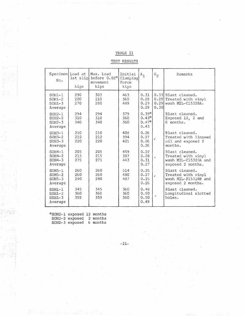
TABLE II
TEST RESULTS
Specimen Load at Max. Load Initial ~l- K2 Remarks
No.1st slip before 0.02 ft Clamping
movement Forcekips kips kips
SOH1-1 290 303 463 0.31 0.33 Blast cleaned.SOHl-2 200 210 360 0.28 0.29 Treated with vinylSOHl-3 270 280 489 0.28 0.29 wash MIL-C15328A.Average 0.29 0.30
SOH2-1 294 294 379 O.39 i': Blast cleaned.SOH2-2 310 310 360 O. 43~': Exposed 12, 2 andSOH2-3 340 340 .360 0.471: 6 months.Average 0.43
SOH3-1 210 210 408 0.26 Blast cleaned.SOH3-2 212 212 394 0.27 .; Treated with linseedSOH3-3 220 220 421 0.26 oil and exposed 2Average 0.26 months.
SOH4-1 205 205 459 0.22 Blast cleaned.SOH4-2 215 215 387 0.28 v Treated with vinylSOH4-3 275 275 443 0.3l wash MIL-C15328A andAverage 0.27 exposed 2 months.
SOHS-l 260 260 514 0.25 Blast cleaned.SOHS-2 260 260 480 0.27 J Treated with vinylSOHS-3 240 240 487 0.25 wash MIL-P15328B andAverage 0.26 exposed 2 months.
SSHl-l 345 345 360 0.48 Blast cleaned.SSHl-2 360 360 360 0.50 Longitudinal.slottedSSHl-3 359 359 360- 0.50
,;holes.
Average 0.49
*SOH2-1 exposed 12 months-SOH2-2 exposed Z monthsSOH2-3 exposed 6 months
-21-

-22-
++++++++
W
..
.. -III A325 Bolts
Series No. Hole WidthTested Dia. IIW"
SOH I :3 I 1/16" 6.40"
SOH 2 3 I 1/4" 6.78 11
SOH :3 3 I 1/411 6.78 11
SOH4 :3 15/1611 6.65 11
SOH 5 :3 I 1/411 6.40 11
Fig. 1 Test Specimens

-23-
6.40 11
III A325 Bolts III A36 12.
.-1
Detail of Slot
Fig. 2 Test Specimens - Slotted Holes Parallel to the Lineof Load
400
300
LOADKIPS
200
100
r --------------- r---~
r----------~----i-r---
0.1 0.2
SLIP (IN.)
0.3 0.4
Fig. 3 Load Slip Diagram of Joint SSHI Blast Cleaned SurfaceI
1'0.p:.I

K
0.7
-........---0.65
0.6
0.5
0.4
0.3 0.30 --+---
0.2 0.20+
+0.49
-25-
Joints With Round Holes(Hole Diameters ~1611- ~411 Oversize)
3Mill ScaleSurfaces
0.1
IMill ScaleSurfaces
2Blast Cleaned
Surfaces(K1)
4Blast Cleaned
Surfaces(K1)
Joints With Slated Holes
Fig. 4 Comparison of Joints 'with Mill Scale and BlastCleaned Surfaces
1. References 1,42. Reference 43. Reference 14. This program

Fig. 5 Faying Surface Damage of SRI Joints
-26-

-27-
----- -----IIf300 11/
I I200
LOADKIPS
100 OHI OHI
CLEAN MILL SCALE
300
200
LOADKIPS
100 SOH I SOH I
o .04 .08
ELONGATION (IN.)
.04 .08
SLIP (IN.)
Fig. 6 Comparison of Clean Mill Scale Specimens and Vinyl WashCoating Without Exposure

0.5
0.4 Univ. of Washington Tests
KA(t '\
0.3 +0.2
Clean Mill Vinyl WashScale CI5328 A PI5328A CI5328 A
0.1 \ )y
Blast Cleaned and Treated
Fig. 7 Tests Results Without Exposure
-28-
300
200
LOADKIPS
100Without
ExposureWithoutExposure
-29-
o
300
.04 .08
ELONGATION (IN.)
o .04 .08SLIP (IN.)
200
LOADKIPS
100
·----r------r--·-r-----'
Two Months Exposure
o .04 .08 1.2SLIP (IN.)
1.6 .20
Fig. 8 Comparison of Vinyl Wash Coating with and withoutTwo Months Cexposure

0.6 1 ( ( ( ( ( ( ( ./ ./ ./ < < ./ ( C C C C < ( c ./ C ( ./ (I C C C C ././ < ./ ./ ( C ./ / C C C ./ ./ ( ./ I
O.7W//////$///#/////#~t~~7Average) Value <T////@//~For/BI~(Cleaned Surfacesn A r-r --;/T-/-r-7'-/7 ..,-,,-- -+-/--+-1
Untreated Blast Cleaned/ /Surfaces/
Scale
• 6months
• 2 months
12 months
••
//~Average~ Value For///,///,/ / (/
/ /Mill Scale Surfaces~//@dQ
----•
0.4 I :; :; :; ]A:; :; ) ) :; i:; :; :; :; :; ) ) , ; , 7 7 7 , , :; :; 7 :; , I/777 77}77>' "",'///
0.5
0.3
K
~ ••
0.2•
SOHI SSHI SOH2 SOH3 SOH4 SOH 5
C15328 A Slotted Holes
0.1 r\. Jy
Without Exposure
RustedJoints
Linseed C15328 A P 15328 B~ Oil ~
YE~posed Two Months
Fig. 9 Summary of Test Results on Specimens with Blast·Cleaned Surfaces.
ILNoI

0.7
0.6
•
•
•
0.5
•K
•0.4 •
//"Untreated Mill' Scale,Su;faces/
0.3 - # # T # T T TT T T T T # ,/
0.2
0.1
o 2 4 6 8EXPOSURE TIME - MONTHS
10 12
Fig. 10 Effect of Exposure on Slip Coefficient with BlastCleaned Surfaces
IeN}-JI
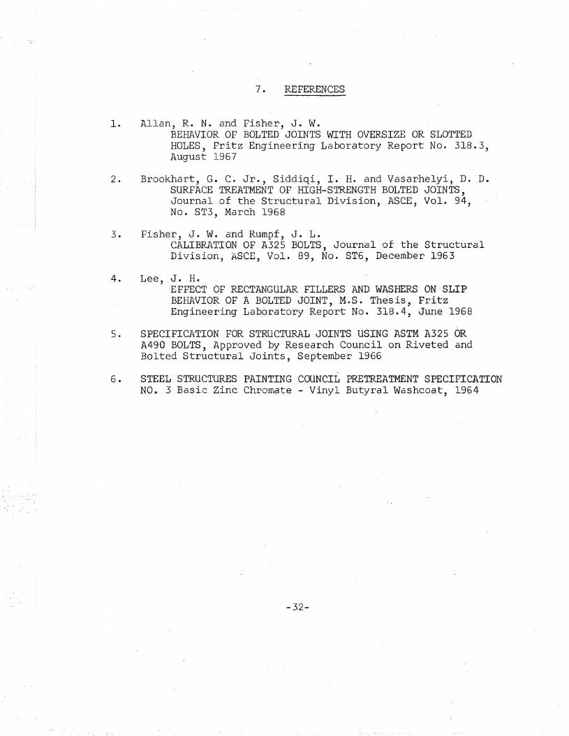
7. REFERENCES
1. Allan, R. N. and Fisher, J. W.BEHAVIOR OF BOLTED JOINTS WITH OVERSIZE OR SLOTTEDHOLES, Fritz Engineering Laboratory Report No. 318.3,August 1967
2. Brookhart, G. C. Jr., Siddiqi, I. H. and Vasarhelyi, D. D.SURFACE TREATMENT OF HIGH-STRENGTH BOLTED JOINTS,Journal of the Structural Division, .ASCE, Vol. 94,No. ST3, March 1968
3. Fisher, J. W. and Rumpf, J. L.CALIBRATION OF A-325 BOLTS, Journal of the StructuralDivision, ASeE, Vol. 89, No. ST6, December 1963
4. Lee, J. H.EFFECT OF RECTANGULAR FILLERS AND WASHERS ON SLIPBEHAVIOR OF A BOLTED JOINT, M.S. Thesis, FritzEngineering Laboratory Report No. 318.4, June 1968
5. SPECIFICATION FOR STRUCTURAL JOINTS USING ASTM A325 ORA490 BOLTS, Approved by Research Council on Riveted andBolted Structural Joints, September 1966
6. STEEL STRUCTURES PAINTING COUNCIL PRETREATMENT SPECIFICATIONNOo 3 Basic Zinc Chromate - Vinyl Butyral Washcoat, 1964
-32-