effect of steel flow control devices on …imim.pl/files/archiwum/vol2a_2015/45.pdf · effect of...
TRANSCRIPT
A R C H I V E S O F M E T A L L U R G Y A N D M A T E R I A L S
Volume 60 2015 Issue 2
DOI: 10.1515/amm-2015-0216
L. SOWA∗ ,]
EFFECT OF STEEL FLOW CONTROL DEVICES ON FLOW AND TEMPERATURE FIELD IN THE TUNDISH OF CONTINUOUSCASTING MACHINE
WPŁYW URZĄDZEŃ STERUJĄCYCH PRZEPŁYWEM STALI NA POLE PRĘDKOŚCI I TEMPERATURY W KADZI POŚREDNIEJURZĄDZENIA CIĄGŁEGO ODLEWANIA
The mathematical model and numerical simulations of the liquid steel flow in a tundish are presented in this paper. Theproblem was treated as a complex and solved by the finite element method. One takes into consideration in the mathematicalmodel the changes of thermophysical parameters depending on the temperature. The single-strand tundish is used to castingslabs. The internal work space of the tundish was modified by flow control devices. The first device was a pour pad situatedin the pouring tundish zone. The second device was a dam. The third device was a baffle with three holes. The dam and bafflewere placed in the tundish at different positions depending on the variant. The main purpose of using these was to put barriersin the steel flow path as well as give directional metal flow upwards which facilitated inclusion floatation. The interaction offlow control devices on hydrodynamic conditions was received from numerical simulations. As a result of the computationscarried out, the liquid steel flow and steel temperature fields were obtained. The influences of the tundish modifications onthe velocity fields in liquid phase of the steel were estimated, because these have essential an influence on high-quality of acontinuous steel cast slab.
Keywords: Numerical simulation, molten metal flow, continuous casting, tundish
W pracy przedstawiono model matematyczny i wyniki symulacji numerycznych przepływu ciekłej stali w kadzi po-średniej urządzenia ciągłego odlewania. Zadanie potraktowano kompleksowo rozwiązując go metodą elementów skończonych.Uwzględniono zmianę parametrów termofizycznych od temperatury. Do rozważań wybrano jednowylewową kadź pośredniąprzeznaczoną do odlewania wlewków płaskich. Przestrzeń robocza kadzi pośredniej była modyfikowana i zabudowywana urzą-dzeniami sterującymi przepływem ciekłej stali. Pierwszym urządzeniem była kształtka podwylewowa umieszczona w strefiezasilania kadzi pośredniej. Drugim urządzeniem była tama a trzecim przegroda z trzema oknami przelewowymi. Tama iprzegroda były umiejscawiane zamiennie w różnych położeniach zależnie od wariantu. Głównym celem zastosowania tychmodyfikacji było wymuszenie spokojnego mieszania cieczy metalicznej oraz ukierunkowanie płynięcia metalu w górę, którewspomaga flotacyjne unoszenie wtrąceń do warstwy żużla. Wpływ zastosowanych w kadzi pośredniej urządzeń sterującychna warunki hydrodynamiczne przepływu ciekłej stali oceniano na podstawie symulacji komputerowych. W wyniku obliczeńnumerycznych otrzymano pola prędkości i temperatury ciekłej stali. Analizowano wpływ modyfikacji wnętrza kadzi na rozkładyprędkości w fazie ciekłej stali, które mają istotny wpływ na jakość wlewka ciągłego odlewania.
1. Introduction
The method of continuous casting of steel is now oftenused in the metallurgical industry, due to the increasing de-mand for the production of high-quality steel. There is there-fore a need for continuous improvement of this method byproposing of new technical solutions in different elements ofthe continuous casting machine. The obtainment of qualitysteel from a continuous casting machine is dependent on alarge number of interlinked process parameters of main ladle,tundish and continuous steel casting (CSC) mould [1]. Moltensteel at an appropriate temperature is poured from the mainladle to the tundish at a preset rate and then flows over this ves-sel and fills it up to a specified height. Next, the steel flows out
through the openings in the tundish bottom to the CSC mould[2]. An important device of continuous casting machine is thetundish, in which a stabilized steel flow has a crucial affect onthe quality and efficiency conditions of the continuous castingprocess. The paper mainly focuses on the analysis of flowand thermal phenomena occurring in the tundish. Nowadays,tundish is not only a storage vessel which guaranty the contin-uous casting of steel, but it become an additional metallurgicalstage where other operation are performed. These operationsare for example the temperature control of alloy and chemicalcomposition, the melt flow control to enable the non-metallicinclusion separation and transport them to the slag layer. Flowbehaviour in the tundish is governed mainly by the size andshape of the tundish and the location of flow control devices,
∗ INSTITUTE OF MECHANICS AND MACHINE DESIGN, CZESTOCHOWA UNIVERSITY OF TECHNOLOGY, 73 DĄBROWSKIEGO STR., 42-201 CZESTOCHOWA, POLAND] Corresponding author: [email protected]
844
such as dams, weirs, filters, pour pad, baffles with holes andturbulence inhibitors [3, 4]. These devices are designed to al-low the implementation of the main objective of the flow in thetundish which is to ensure uniformity and inclusion removal,while avoiding flow-related problems. Tundish flow problemsinclude the surface turbulence, short-circuiting, dead zonesand vortexing. An excessive flow directed across the top sur-face can produce turbulence and lead to reoxidation and slagentrainment. Short-circuiting allows incoming steel from theladle to exit prematurely into the CSC mould with insufficienttime for inclusion flotation. Dead zones are stagnant, colderregions that inhibit inclusion removal and can slowly mix andcontaminate the new steel flowing through the tundish. If theliquid level is too shallow, high-speed, asymmetric flow mayproduce vortexing, which can entrain surface slag down intothe CSC mould. Generally summarize, for the designing ofa tundish arrangement, it is necessary to look for the high-est plug flow volume fraction with a minimum dead volumeand perfect mixing zones [2-5]. An important mechanism forinclusion elimination from liquid steel is a simple flotation,whereby the particle is separated if it rises as the result ofits buoyancy to contact the slag and is then absorbed by theslag. However, the efficiency of inclusion removal by simpleflotation in the tundish is generally limited by the residencetime of liquid metal as it flows through a tundish and therise velocity of the buoyant particles. The rise velocity of aparticle is a function of its size, smaller particles are harderto remove [6-8]. The flow pattern is also affected by the steelflow rate and its temperature distribution. Thermal buoyancytends to lift up the hotter, lower-density flowing steel, whilecolder steel tends to flow down the walls and along the bottom.A temperature difference of only a few degrees is enough tolift the jet flowing beneath the weir and completely reverse theflow direction in the tundish. Flow in the tundish is greatlyaffected by the ladle-tundish nozzle geometry and gas in theladle stream. Problems related to surface turbulence can bereduced by avoiding excessive argon levels in the ladle streamand by using fully-shrouded and immersed nozzles [5-7]. Em-pirical studies of the liquid metal flow in the tundish, dueto the high temperatures and a lack of optical access, arealmost impossible. For this reason, the numerical modellingis currently the main tool for analyzing the phenomena ofcontinuous casting process [1-6, 8-10]. In the present study,the numerical simulation was used.
The mathematical and numerical simulation model of theliquid steel flow in a tundish is presented in this paper. Theproblem was treated as a complex and solved by the finiteelement method [8-11]. The velocity fields are obtained bysolving the momentum equations and the continuity equa-tion, whereas the thermal fields are calculated by solving theconduction equation with convection term. The internal workspace of the tundish was modified by the flow control de-vices. The main purpose of using these devices was to causea quiet liquid mixing as well as give directional metal flowupwards which facilitated inclusion floatation. The interactionof flow control devices on hydrodynamic conditions was re-ceived from numerical simulation. As a result of the compu-tations carried out, the liquid steel flow and steel temperaturefields were obtained. The influence of the tundish modificationon velocity fields in the liquid phase of steel was estimated,
because these have an essential influence on high quality of acontinuous steel cast slab.
2. Mathematical model of the heat-transfer during themolten metal motions
The mathematical model of a molten metal flow in thetundish has been proposed. The superheated metals and theiralloys in the liquid state can be treated as Newtonian fluids[5, 6, 8-12], therefore in the paper is used the system of equa-tions (2, 3) which describe the flow of viscous incompressiblefluid. The equation (1) describes the heat transfer in the regionof a tundish is based on solving the Fourier-Kirchhoff equationwith the convection term [5, 6, 8-14]. It was assumed that thesolidification front is mushy [8-14], but sometimes it is as-sumed that it can be sharp [15, 16]. The assumption of suchmodel (the mushy zone) allowed us to introduce the phasetransformation enthalpy to the effective thermal capacity inthe energy equation in the problem solution. The mathemati-cal model is based on the solution of the following system ofdifferential equations [8-12]:– the energy equation
Ce f
(∂T∂t
+ v j∂T∂x j
)=
∂
∂x j
(λ∂T∂x j
), (1)
– the momentum equations
ρ
(∂vi
∂t+ v j
∂vi
∂x j
)=
∂
∂x j
(µ∂vi
∂x j
)− ∂p∂xi
+ ρgi β (T − Tin) + ρgi,
(2)– the continuity equation
∂vi
∂xi= 0, (3)
where: T – the temperature [K], t – time [s], ρ = ρ(T ) –the density [kg/m3], λ – the thermal conductivity coefficient[W/(mK)], x j – the coordinates of the vector of a considerednode’s position [m], vi – the velocity vector of a molten metalflow [m/s], µ(T ) – the dynamical viscosity coefficient [Ns/m2],Ce f (Ce f = ρLScLS + (ρSL)/(TL-TS) [8]) – the effective heatcapacity of the mushy zone [J/(m3K)], L – the latent heat ofsolidification [J/kg], cLS – the specific heat of the mushy zone[J/(kgK)], p – the pressure [N/m2], ρS, ρL, ρLS – the densityof solid phase, liquid phase, and mushy zone, respectively[kg/m3], gi – the vector of the gravity acceleration [m/s2], β –the volumetric thermal expansion coefficient [1/K], Tin – theinitial temperature (tundish inlet) [K].
The equation of heat conductivity (1), the Navier-Stokesequations and continuity equation (2, 3) create a closed, cou-pled system of equations describing the molten metal flow.This system of equations is completed by the appropriate ini-tial conditions and the classical boundary conditions [8-18].
The initial conditions for velocity fields and temperaturefields are given as:
v(xi, t0) = v0(xi), T (xi, t0) = T0(xi) . (4)
845
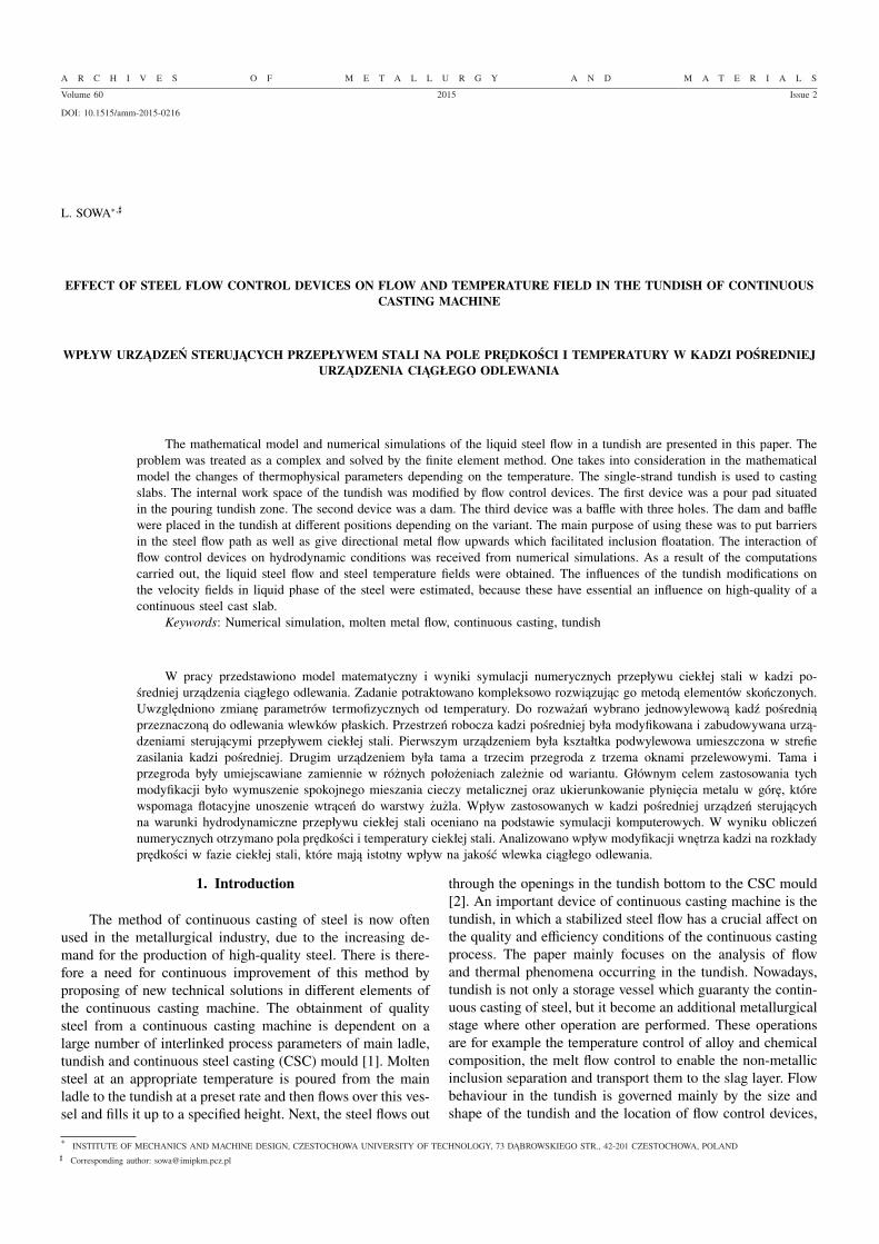
Fig. 1. A schematic illustration of the single-strand tundish containingthe flow control devices
The boundary conditions, on the indicated surfaces(Fig. 1), specified in the considered problem were as follows:– at the inflow nozzle
vy = vin, vx = 0, T = Tin, (5)
– at the tundish wall
vx = vy = 0, λ∂ T∂ n
= −αt (T − Ta) (6)
– at the slag layer
vy = 0, λ∂ T∂ n
= −αs (T − Ta) (7)
– at the outflow nozzle
vx = 0,∂ T∂ n
= 0 (8)
where: Ta – the ambient temperature [K], αt – the heat-transfercoefficient between the steel tundish wall and ambient[W/(m2K)], n – the outward unit normal surface vector.
The above problem was solved by the finite elementmethod in the weighted residuals formulation [8-11, 15-17].
3. Numerical simulations
The calculations were performed for the tundish with across-section 3.3×1.44 and the length 4.7 m (Fig. 1). Theheight of the dam and baffle was equal to 0.27 m. The over-heated steel with temperature Tin = 1900 K was poured withvelocity vin = 0.45 m/s into the tundish with the initial tem-perature Tt = 1400 K. The thermophysical properties of thecast steel and tundish were taken from works [2, 4, 6, 11 - 14].The linear change of the density (ρ) and thermal conductiv-ity (λ) were assumed in the TL – TS temperature interval.The variability of the dynamical viscosity coefficient (µ) withrespect to temperature was determined according to the expo-nential relationship in range 0.003 – 105 [Ns/m2] [19, 20]. Thecharacteristic temperatures of the molten steel were equal to:TL = 1810, TS = 1760 K and ambient temperature Ta = 303 K.The heat-transfer coefficient (α) between the tundish and am-bient was equal αt = 30 W/(m2K) and between the slagand ambient αs = 3 W/(m2K) [1, 9]. The thermal and flu-id flow phenomena occurring in the considered system wereanalyzed. The internal working space of the tundish has been
modified by the location of added flow control devices, suchas the pour pad, dam and baffle with three holes. In numericalcalculations five variants location of the flow control devicesinside the tundish, were taken into account. In I variant thepour pad was used only in the inflow zone. In II variant thedam was used additionally in the outflow zone. In III variantthe baffle with three hols was located in the outflow zone. InIV variant the dam and baffle ware used together. In V variantthe two baffles were applied. An influence of the interactionof this flow control devices on the velocity fields in the liquidphase of steel were estimated. The main objective of the veloc-ity field change was to enable the separation of non-metallicinclusions and directed metal flow upwards which facilitatedthe floatation of inclusions. Examples of calculation resultsare shown in the form of the temperature and velocity fields(Fig. 2-9).
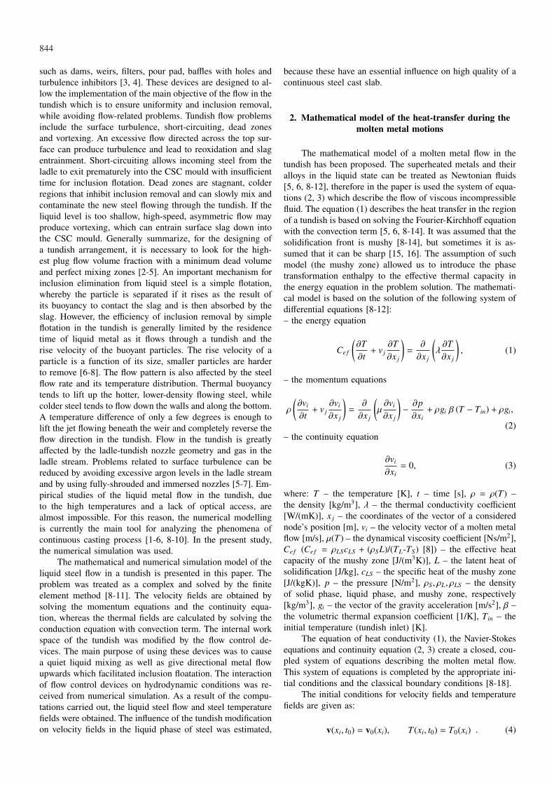
Fig. 2. Velocity vectors and temperature field after time 720 s, Ivariant
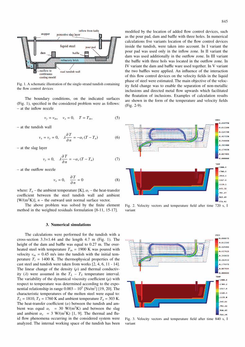
Fig. 3. Velocity vectors and temperature field after time 840 s, Ivariant

846
Fig. 4. Velocity vectors and temperature field after time 720 s, IIvariant
Fig. 5. Velocity vectors and temperature field after time 720 s, IIIvariant
Fig. 6. Velocity vectors and temperature field after time 720 s, IVvariant
Fig. 7. Velocity vectors and temperature field after time 840 s, IVvariant
Fig. 8. Velocity vectors and temperature field after time 720 s, Vvariant
Fig. 9. Velocity vectors and temperature field after time 840 s, Vvariant
847
4. Conclusions
The paper mainly focuses on the analysis of flow andthermal phenomena occurring in the tundish. Investigations ofthe steel flow or inclusions separation process at the industrialplant are nearly impossible because of the high temperatureand a lack of optical accessibility. For this reason the nu-merical modelling is becoming an important tool to analyzeall phenomena of the continuous casting process. This paperpresents the coupled model of the fluid flow and heat transferin the tundish during continuous casting processes. The prob-lem was treated as a complex and solved by the finite elementmethod. Numerical simulation results are shown in the formof the temperature and velocity fields (Fig. 2-9). It was not-ed, that the velocity field of a liquid phase has a significantinfluence on the temperature field. A small intensity of themolten metal motion near the slag layer causes the formationof dead zones and the local temperature drop in the inflowand outflow tundish zone (Fig. 2, 3). Next, four modificationvariants of the internal work space of the tundish were per-formed (Fig. 4-9). In the second variant, the dam causes theexcessive flow directed to the top surface what can lead tothe reoxidation and slag entrainment down into the continuoscasting mould (Fig. 4). In this case, the small movements ofthe liquid phase in the central zone of the tundish occur be-cause the main stream of liquid metal flows after the bottomof it. The use of the baffle with three holes causes the liquidmetal moves return and reducing dead zones (Fig. 5). In thefourth variant, when the dam and baffle are used together,the appropriate directed flow of molten metal was obtained.The main directed flow slightly to the top surface causes thecirculating movements of molten metal in the whole tundishallow flowing of the non-metallic inclusions to the slag layer(Fig. 7). Similarly, satisfying results were obtained in caseof a fifth variant. In this case, the minimum dead volumeis visible because the baffle gives a directional metal flowupwards allowing the inclusions to float toward the slag layer(Fig. 9). Generally summarize, the flow field inside the tundishis frequently unsteady and is an important mechanism for in-clusion elimination from liquid steel allowing the inclusionsto float toward the slag layer. It has an essential influence on
obtain high-quality of the continuous steel cast slab. It is veryimportant for the practice casting.
REFERENCES
[1] R. Pardeshi, S. Basak, A.K. Singh, B. Basu, V. Mahashabde,S.K. Roy, S. Kumar, ISIJ Int. 44, 1534-1540 (2004).
[2] T. Merder, J. Jowsa, A. Bogusławski, Arch. Metall. Mater. 50,933-953 (2005).
[3] T. Merder, Arch. Metall. Mater. 58, 1111-1117 (2013).[4] A. Cwudziński, J. Jowsa, Arch. Metall. Mater. 57, 297-301
(2012).[5] S. López-Ramı́rez, J. De, J. Barreto, P. Vite-Martı́nez, J.A.
Romero Serrano, C. Duran-Valencia, Metall. Mater. Trans. B35, 957-966 (2004).
[6] Y. Miki, B.G. Thomas, Metall. Mater. Trans. B 30, 639-654(1999).
[7] J. Lamut, J. Falkus, B. Jurjevec, M. Knap, Arch. Metall. Mater.57, 319-324 (2012).
[8] L. Sowa, A. Bokota, Arch. Metall. Mater. 57, 1163-1169(2012).
[9] L. Sowa, Arch. Foundry Eng. 14, 103-106 (2014).[10] T. Telejko, Z. Malinowski, M. Rywotycki, Arch. Metall. Mater.
54, 837-844 (2009).[11] W. Piekarska, M. Kubiak, A. Bokota, Arch. Metall. Mater. 56,
409-421 (2011).[12] W. Piekarska, M. Kubiak, Appl. Math. Model. 37, 2051-2062
(2013).[13] W. Piekarska, M. Kubiak, Z. Saternus, Arch. Metall Mater. 57,
1219-1227 (2012).[14] W. Piekarska, M. Kubiak, Z. Saternus, Arch. Metall. Mater.
58, 1391-1396 (2013).[15] T. Skrzypczak, E. Węgrzyn-Skrzypczak, Int. J. Heat Mass Tran.
55, 4276-4284 (2012).[16] T. Skrzypczak, Arch. Metall. Mater. 57, 1189-1199 (2012).[17] A. Bokota, T. Domański, Arch. Metall. Mater. 54, 575-587
(2009).[18] T. Domański, A. Bokota, Arch. Metall. Mater. 56, 325-344
(2011).[19] B. Zhao, S.P. Vanka, B.G. Thomas, Int. J. Heat Fluid Fl. 26,
105-118 (2005).[20] K. Miłkowska-Piszczek, M. Korolczuk-Hejnak, Arch. Metall.
Mater. 58, 1267-1273 (2013).
Received: 20 April 2014.