effect of scaling on design and operation of thermal seawater desalination plants steam/2002 fwg and...
TRANSCRIPT

SCALING_Colour_E.doc Page 1 of 18 Dr. Greffrath/SERCK COMO GmbH/17.09.02
Effect of Scaling on Design and Operation ofThermal Seawater Desalination Plants
Dr. Rainer GreffrathSERCK COMO GmbH
Pankower Str. 16D-21504 Geesthacht
Germany
Tel.: ++49-4152-805-0Fax.: ++49-4152-805-105E-Mail: [email protected]: www.serckcomo.com
This document, and more, is available for download at Martin's Marine Engineeirng Page - www.dieselduck.net

SCALING_Colour_E.doc Page 2 of 18 Dr. Greffrath/SERCK COMO GmbH/17.09.02
1. Introduction
Scaling of heat transfer and evaporation surfaces has different effects on the designand operation of evaporators and related heat transfer equipment. The process anddesign engineers have to consider that scaling reduces effectiveness (productionand/or heat consumption) of the process. As in many cases the supplier has to guar-antee that within a certain operation period the full production is maintained and con-sumption figures are not exceeded, scale formation – as far as not completely avoid-able by other measures – will require over-sizing of the evaporation/heat transfer sur-faces, thus creating significant increase of investment cost.
In this presentation the different ways how scaling affects the main thermal evapora-tion processes will be explained:
MED = Multi-Effect DistillationMED-MVC = MED, driven by means of Mechanical Vapour CompressionMED-TVC = MED, driven by means of Thermal Vapour CompressionMSF (Multi Stage Flash), as Once-Through or Brine Recirculation Process
For better comparison all curves in this presentation shown for the a. m. processeshave been computed on the basis of plants with the same thermal efficiency (324kJ/kg).
As one of SERCK COMO’s main business is the marine sector, some informationwill be given about the problems with scaling in ship evaporators.
This document, and more, is available for download at Martin's Marine Engineeirng Page - www.dieselduck.net

SCALING_Colour_E.doc Page 3 of 18 Dr. Greffrath/SERCK COMO GmbH/17.09.02
2. Scaling in MSF Evaporators
2.1 MSF Working Principle
The main characteristic of the MSF process is that heat transfer to the seawater orbrine and the evaporation procedure itself take place separately. In a flash evaporator(Fig. 1 and Fig. 2) the seawater/brine is heated up to a certain top temperature
Steam Seawater Return
DieselJacket Water
Seawater Condensate
Distillate Jacket Water Return Remixing
Brine Return
Fig. 1: MSF Once-Through Plant for heat Supply from Diesel Engine
Noncondensable Gases
Seawater Return
Steam Stripping Steam
FeedwaterOverhead Vapour
Brine Heater Heat Recovery Section Heat RejectionSection
Seawater
Condensate Brine Blowdown
Distillate
Deaerator
AntiscaleChemicalDosing
EvacuationUnit
Fig. 2: MSF Plant with Brine Recirculation
This document, and more, is available for download at Martin's Marine Engineeirng Page - www.dieselduck.net

SCALING_Colour_E.doc Page 4 of 18 Dr. Greffrath/SERCK COMO GmbH/17.09.02
(BTT = between 88°C and 118 °C according to the design philosophy of the plant).This heating procedure takes place under pressure, boiling during heat transfer isstrictly avoided. As thus the velocity of thermal distortion of the bicarbonates isminimized, scaling is reduced to a minimum, but it still takes place. Velocity of pre-cipitation of calcium Carbonate is an exponential function of the temperature. A moreconservative design applies a low brine top temperature. Once through evaporators –due to the fact of a very low concentration factor of the seawater (cf < 1.1) – are lesssensitive than MSF evaporators with brine recirculation (cf=1.5 – 2). In addition, Thebrine recirculation plants may suffer from Magnesium-Hydroxide scales, caused bythe effect of pH-rise in recirculation brine.
2.2 Consideration of Scaling in MSF Evaporator Design
In many cases the customer specifies a minimum operating period between chemicalcleanings of the plant or he requests to design the condenser surfaces for a certainfouling factor (FF). FF is often – as in this presentation – called a factor, althoughhaving the inverse dimensions of the heat transfer coefficient (OHTC): m2K/ W.
The optimisation of a MSF plant to be designed for a certain capacity and thermalefficiency takes place by “playing” with the following main design parameters:
- Tube length- Tube diameter- Number of tubes- Number of stages
The brine top temperature, the max seawater temperature and the selected process(recirculation or once-through) affect this design as well, and – of course – the foul-ing factor “FF”. How FF influences the design of once-through evaporators is shownby a typical example:
The first possibility for installing reserve surface is to lengthen the condenser tubes(Fig.3). The application of this method only leads soon to a very wide and shortevaporator vessel with unfavourable proporations. (in units with smaller capacitiesthe condensers can have more than 1 pass in order to reduce tube length, not consid-ered here).
The second possibility is to reduce the tube diameter. As in many cases – with respectto the possibilities of a mechanical cleaning – minimum tube diameters are specified,there is in most cases not much room to play with this parameter and for this reasonthis is not considered here.
This document, and more, is available for download at Martin's Marine Engineeirng Page - www.dieselduck.net

SCALING_Colour_E.doc Page 5 of 18 Dr. Greffrath/SERCK COMO GmbH/17.09.02
Tube Length of Condensers of MSF Once Through Evaporator versus Design Fouling Factor, Flow Velocity in tubes = const. = 1.8 m/s
(1000 t/d, 324 kJ/kg, BTT=90°C, TSEA=32°C, 4,5% TDS16mm CuNi9010-Tubes, 2-pass-condensers, w=1.8 m/s)
1500
2000
2500
3000
3500
4000
4500
0,000000 0,000050 0,000100 0,000150
Design Fouling Factor (m2 K / W)
(mm)
13 stages14 stages15 stages16 stages17 stages18 stages
Fig. 3: Influence of Design-FF on the Tube Length
The third possibility is to add additional tubes in the condenser. This will soon lead touneconomically low flow velocities (Fig. 4) in the condenser tubes. The drop of
Flow Velocity in Condenser Tubes of MSF Once Through Evaporator versus design Fouling Factor, Tube Length = const. = 2800 mm
(1000 t/d, 324 kJ/kg, BTT=90°C, TSEA=32°C, 4,5% TDS16mm CuNi-Tubes, 2-passes, L-Tube = 2800 mm)
0,50
1,00
1,50
2,00
2,50
3,00
3,50
4,00
4,50
0,000000 0,000050 0,000100 0,000150
Design Fouling Factor (m2 K / W)
(m/s)
13 stages14 stages15 stages16 stages17 stages18 stages
Fig. 4: Influence of Design-FF on Velocity in Tubes (l-tube=const.)
This document, and more, is available for download at Martin's Marine Engineeirng Page - www.dieselduck.net

SCALING_Colour_E.doc Page 6 of 18 Dr. Greffrath/SERCK COMO GmbH/17.09.02
velocity is accelerated by the decreasing heat transfer coefficients in the tubes, re-sulting in an over-proportional increase of number of tubes.
The most common method for consideration of tube fouling/scaling is to add stages.It should always be always tried to use standardised stage geometries in order tominimise design and manufacturing cost. The typical result of such an optimisation isshown in Fig. 5a/b. Tube length is constant, the fine adjustment of the thermal effi-ciency takes place by varying the number of tubes. The flow velocities are thusvarying within the range acceptable for the selected CuNi-tubes.
1314
1617
10
11
12
13
14
15
16
17
18
Nu
mb
er o
f S
tag
es
0,000000 0,000050 0,000100 0,000150
Design Fouling Factor (m2 K / W)
Optimized Number of Stages of MSF Evaporator (1000 t/d, 324 kJ/kg, BTT=90°C, TSEA=32°C, 4,5%TDS, Once Through, Ltube=2800mm, 2
passes)
Fig. 5a: Optimisation of Number of MSF-Stages
1694
20222153
2455
15001600170018001900200021002200230024002500
(m2)
0,000000 0,000050 0,000100 0,000150
Design Fouling Factor (m2 K / W)
Total Condenser Surface of optimized MSF Evaporator (1000 t/d, 324 kJ/kg, BTT=90°C, TSEA=32°C, 4,5%TDS, Once Through,
Ltube=2800mm, 2 passes)
Fig. 5b: Flow Velocities in Tubes of optimised MSF Evaporator
This document, and more, is available for download at Martin's Marine Engineeirng Page - www.dieselduck.net

SCALING_Colour_E.doc Page 7 of 18 Dr. Greffrath/SERCK COMO GmbH/17.09.02
In this example of a Once-Through MSF Evaporator (design data given in the dia-grams) we have to increase the number of identical stages from 13 (no fouling allow-ance considered) to 17 (for FF = =.000150 m2 K / W). The cost portion of the evapo-rator in a complete unit may be approx. 60 %, cost increase of total MSF-unit due toconsideration of fouling will be – correspondingly - approx. 18 %.
2.3 Effect of Scaling/Fouling on Operation of MSF Evaporators
How does such an over-dimensioned evaporator behave in operation? As the waterproduction in an MSF evaporator is proportional to the flashing seawater/brine flowand the flash temperature range, the influence of tube scaling/fouling on the waterproduction is principally negligible. As the LMTD in the condensers forms part of thetemperature rise in the brine heater, the heat consumption dependes strogly on thefouling of the tubes. This effect is shown in Fig. 6. A flash evaporator with given
Specific Heat Consumption versus actual Fouling Factor of MSF Evaporator
(1000 t/d, 324 kJ/kg, BTT=90°C, TSEA=32°C, 4,5%TDSOnce Through, Ltube=2800mm, 2 passes, Design-FF = 0,000150 m2 K / W)
240
250
260
270
280
290
300
310
320
330
0,000000 0,000050 0,000100 0,000150
Fouling Factor in Operation (m2 K / W)
Spe
cific
hea
t Con
sum
ptio
n (k
J/kg
)
Design Point
Fig. 6: Influence of actual Fouling Factor on Heat Consumption
data, designed for FF=0.000150 m2 K / W should have – when being clean – a heatconsumption of 75% of design value only. The author has the experience that suchenergy savings in clean evaporators are not always found during commissioning al-though they should. It seems that very often the fouling allowance is partially “con-sumed” by temperature losses on the condensation side due to partial pressure of CO2
in the condensers, caused by an improper design of the gas extraction zones. An in-telligent customer should request in the tender specification for a performance test ofthe clean evaporator for verification of the design-FF.
This document, and more, is available for download at Martin's Marine Engineeirng Page - www.dieselduck.net

SCALING_Colour_E.doc Page 8 of 18 Dr. Greffrath/SERCK COMO GmbH/17.09.02
3. MED-Evaporators
3.1 HTE-Working Principle
Most of the existing MED-Evaporators for seawater desalination apply the HTE-Principle as shown in Fig. 7. A distribution system (not necessarily using spray noz-zles as shown), distributes the feed water on top of the horizontal tube bundle. Thefeed water flows from tube row to tube row and partially evaporates. A typical feedwater/distillate ratio is 3 : 1, which means that 33.3% of the feed water are evaporat-
Feed water (3 t per t of distillate)
Vapour to nextEffect
Demister
Brine Outlet
PRINCIPLE OF HORIZONTAL TUBE (FALLING FILM) EVAPORATION (HTE)
Full Cone Spray Nozzle(s)
Produced Vapours
Heating Vapours fromprevious effect
Fig. 7: Working Principle of Horizontal Tube (Falling Film) Evaporator
ing. The main problem in designing such evaporators is to ensure a sufficient flow offeed water on the tubes (given as kg / s / m tube length). A practical low limit knownto the author is 0.032 kg/s/m for 24mm tubes (such figures are of course subject toindividual experience of the different suppliers). It is good to have many tubes in thevertical direction because this keeps the flow per tube high. This means that for anevaporator of small capacity it is more difficult to maintain sufficient wetting of tubesthan for a plant with a high capacity.
A high thermal efficiency requires higher evaporation surfaces, which means that –with respect to the scaling risk - it is easier to design an evaporator with low thermalefficiency. When considering design fouling allowances the dilemma is that addingof tube surface lowers the feed water flow per tube and thus automatically increases
This document, and more, is available for download at Martin's Marine Engineeirng Page - www.dieselduck.net

SCALING_Colour_E.doc Page 9 of 18 Dr. Greffrath/SERCK COMO GmbH/17.09.02
the risk of scaling. An increase of the feed water flow – the first idea to overcome theproblem - is no solution. As the feed water is more or less sub-cooled in comparisonto the evaporation temperature in the effect, an increase of the feed water injectionwould increase the heat loss for preheating of the feed-water as well as the productloss due to a direct condensation taking place at the sub-cooled injected feed water.The result of increased feed water injection would be: the thermal efficiency of thewhole evaporator would drop, or in a TVC-driven MED plant again additional sur-face would become necessary for maintaining the desired plant efficiency: a real vi-cious circle!
3.2 Effect of Scaling on the design of an MED-Evaporators
Fig. 8 is the flow diagram of a 4-Effect MED evaporator with feed water preheaters,directly heated by steam. Fig. 9a shows the influence of the design fouling factor onthe evaporation surface to be installed for a 8-effect plant. Consequently the feed wa-
Seawater return
SeawaterSteam
Condensate Distillate
Brine
Fig. 8: Simplified Flow Diagram of MED Evaporatorwith Feed Water Pre-Heaters
This document, and more, is available for download at Martin's Marine Engineeirng Page - www.dieselduck.net

SCALING_Colour_E.doc Page 10 of 18 Dr. Greffrath/SERCK COMO GmbH/17.09.02
Evaporation Surface of 8-Effect HTE-Evaporator(MDIST=1000 t/d, QSPEC=324 kJ/kg, BTT=68°C, CSEA=4.5%, CF=1.5,
D-TUBE=24mm, with Feedwater Preheaters)
2500
3000
3500
4000
4500
5000
5500
0,000000 0,000050 0,000100 0,000150
Design Fouling Factor (m2 K / W)
Eva
po
rati
on
Su
rfac
e (m
2)
Fig. 9a: Evaporation Surface of 8-Effect THE-Evaporator
ter flow per meter tube length is dropping with the design-FF (Fig.9b). For this roughcalculation is was assumed that the length-height-width ratio of the tube bundles is
Fig. 9b: Feedwater Flow per m of Tube Length (d=24mm)in 8-Effect HTE-Evaporator
This document, and more, is available for download at Martin's Marine Engineeirng Page - www.dieselduck.net

SCALING_Colour_E.doc Page 11 of 18 Dr. Greffrath/SERCK COMO GmbH/17.09.02
4:2:1. As thus the top area of the tube bundles grows proportionally to the evapora-tion surface with an exponent of 0.66, the feed water flow per tube drops corre-spondingly. In this example the consideration of the design fouling factors leads to aspecific feed water flow below the allowable limit, so that another tube bundle ge-ometry than given above has to be selected (bundle to be higher and more slim).
3.3 Increase of Feed water Flow
The first idea for enabling better wetting of tubes is to increase the feed water flowper effect. Fig. 10 shows that this is not a very recommendable solution. The disad-vantageous effect of the sub-cooled feed water injection creates a significant increaseof heat consumption with declining design concentration factor and correspondinglyhigher feed water injection rates.
Specific heat Consumption of 8-Effect MED-Evaporator versus Design Brine Concentration Factor
(MDIST=1000 t/d, TSEA=32°C, CSEA=4.5%, BTT=68 °C, with Feedwater Preheaters)
320
330
340
350
360
370
380
1,1 1,2 1,3 1,4 1,5
CF = Concentration Factor (Design)
Sp
ecif
ic H
eat
Co
nsu
mp
tio
n (
kJ/k
g)
Fig. 10: Effect of Design-CF on heat Consumption of 8-Effect MED
3.4 Effect of Scaling on the Operation of an MED Evaporator
As to be seen in Fig. 11a, fouling/scaling of MED evaporation surfaces does not af-fect the thermal efficiency very much. There is a slight increase of heat consumptionwith rising FF due to the fact that the temperatures in the effects rise more quicklythan the feedwater temperatures at inlet of effects. This results in higher heat andproduct losses in the effects.
This document, and more, is available for download at Martin's Marine Engineeirng Page - www.dieselduck.net

SCALING_Colour_E.doc Page 12 of 18 Dr. Greffrath/SERCK COMO GmbH/17.09.02
Fig. 11b shows the increase of the brine top temperature in effect 1 while maintainingthe water production in spite of scaling/flowling of the evaporation tubes. In caseswhere the temperature at the hot end of the plant can not be increased any more (dueto the limited temperature level of the heating source), further scaling leads to a re-duction of production (not shown in the diagram). This has f. i. to be consideredwhen operating such a plant with motor water from a Diesel engine.
Effect of Fouling/Scaling on Heat Consumption of 8-Effect HTE-Evaporator (Simulation)
(MDIST=1000 t/d, QSPEC-Design=324 kJ/kg, BTT=68°C, CSEA=4.5%, CF=1.5, DTUBE = 24 mm, with Feedwater Preheaters)
310
312
314
316
318
320
322
324
326
0,000000 0,000050 0,000100 0,000150
Fouling Factor in Operation (m2 K / W)
Sp
ecif
ic H
eat
Co
nsu
mp
tio
n
(kJ/
kg)
Fig. 11a: Effect of Scaling on Heat Consumption in MED-Plant
Effect of Fouling on Brine Top Temperature required for 100% Production of MED Evaporator
62,0
63,0
64,0
65,0
66,0
67,0
68,0
69,0
0,000000 0,000050 0,000100 0,000150
Fouling Factor in Operation (m2 K / W)
Bri
ne
To
p T
emp
erat
ure
(°C
)
Fig. 11b: Effect of Scaling on Brine Top Temperature in MED-Plant
This document, and more, is available for download at Martin's Marine Engineeirng Page - www.dieselduck.net
SCALING_Colour_E.doc Page 13 of 18 Dr. Greffrath/SERCK COMO GmbH/17.09.02
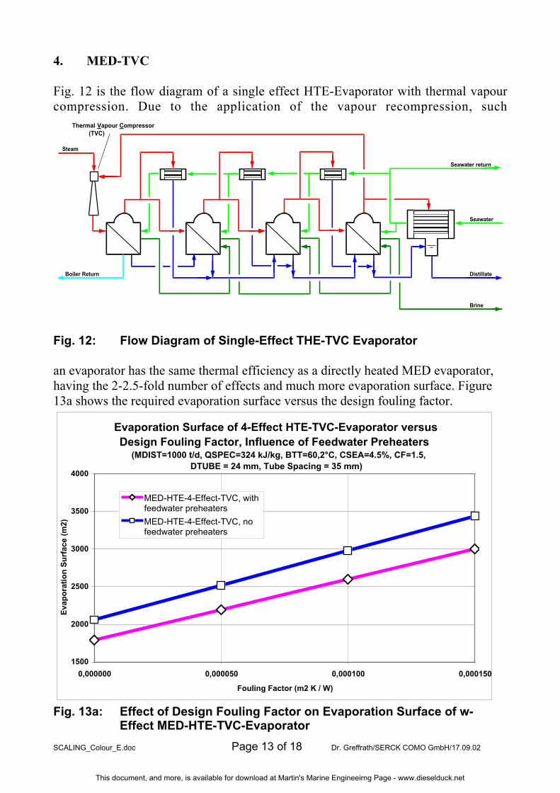
4. MED-TVC
Fig. 12 is the flow diagram of a single effect HTE-Evaporator with thermal vapourcompression. Due to the application of the vapour recompression, such
Thermal Vapour Compressor(TVC)
Steam
Seawater return
Seawater
Boiler Return Distillate
Brine
Fig. 12: Flow Diagram of Single-Effect THE-TVC Evaporator
an evaporator has the same thermal efficiency as a directly heated MED evaporator,having the 2-2.5-fold number of effects and much more evaporation surface. Figure13a shows the required evaporation surface versus the design fouling factor.
Evaporation Surface of 4-Effect HTE-TVC-Evaporator versus Design Fouling Factor, Influence of Feedwater Preheaters
(MDIST=1000 t/d, QSPEC=324 kJ/kg, BTT=60,2°C, CSEA=4.5%, CF=1.5, DTUBE = 24 mm, Tube Spacing = 35 mm)
1500
2000
2500
3000
3500
4000
0,000000 0,000050 0,000100 0,000150
Fouling Factor (m2 K / W)
Eva
po
rati
on
Su
rfac
e (m
2)
MED-HTE-4-Effect-TVC, withfeedwater preheaters
MED-HTE-4-Effect-TVC, nofeedwater preheaters
Fig. 13a: Effect of Design Fouling Factor on Evaporation Surface of w-Effect MED-HTE-TVC-Evaporator
This document, and more, is available for download at Martin's Marine Engineeirng Page - www.dieselduck.net

SCALING_Colour_E.doc Page 14 of 18 Dr. Greffrath/SERCK COMO GmbH/17.09.02
The evaporation surfaces are significantly smaller than in the 8-Effect MED-plant -approx. 60% with and 70% without feed water pre-heaters, at the same thermal effi-ciency. With respect to the scaling risk it is better to equip such a TVC evaporatorwith feed water pre-heaters because this reduces the evaporation surfaces by approx.13% and thus the problems of feed water distribution significantly. The specific feedwater flow (Fig. 13b) remains – even at full design fouling factor – above the criticallimit. This means that – when applying the thermal vapour com pression - it is easier
Fig. 13b: Effect of design Fouling Factor on Feedwater Flow onEvaporator Tubes
to maintain sufficient feed water flows on the tubes than in a comparable directlyheated MED evaporator.
A special risk arises from the operating characteristics of the thermal vapour com-pressor. Fig. 14 is a typical pressure characteristic curve of a Thermo-Ejector. A 4-Effect MED-Evaporator designed for a heat consumption of 324 kJ/kg, operated with10 bar steam, will have a design temperature difference between effect 1 and effect 4of approx. 20 K, where a thermo compressor can recompress approx. 1 t of vapourper 1 t of motive steam. In clean condition, the delta-t between effect 1 and 4 willdrop to approx. 15K, without change in the suction flow of the ejector. In case of ex-ceeding the design fouling factor in operation, the suction flow will sharply drop andmay even become instable, creating a corresponding drop and fluctuations of water
This document, and more, is available for download at Martin's Marine Engineeirng Page - www.dieselduck.net

SCALING_Colour_E.doc Page 15 of 18 Dr. Greffrath/SERCK COMO GmbH/17.09.02
production. This means that in a TVC-driven evaporator it is still more important toinstall sufficient fouling allowances than in a directly heated MED evaporator. ONthe other hand the required surfaces are smaller than in a directly heated MED plant.
Relative Suction Flow of Steam Jet Ejector for Thermal Vapour-Recompression
0,00
0,20
0,40
0,60
0,80
1,00
1,20
0,0 50,0 100,0 150,0 200,0 250,0 300,0
Back Pressure (mbar abs)
Suc
tion
Flow
(kg/
kg)
Fig. 14: Typical Pressure Characteristics of a Thermo-Compressor
An increase of feed water flow (= reduction of concentration factor cf) is not such aproblem as well (Fig. 15). Especially when using feed water pre-heaters, the additio-nally required evaporation surface for maintaining the specific heat consumption isacceptable.
Evaporation Surface of MED-TVC-4-Effect Evaporator versus Brine Concentration Factor
(MDIST=1000 t/d, TSEA=32°C, CSEA=4.5%, BTT=61 °C, QSPEC=324 kWh/t,with Feedwater Preheaters)
2500
3000
3500
4000
4500
5000
5500
1,1 1,2 1,3 1,4 1,5CF = Concentration Factor
Eva
po
rati
on
Su
rfac
e (m
2)
A-Evap (MED-TVC with preheaters)
A-Evap (MED-TVC without preheaters)
Fig. 15: Effect of Design-CF and the presence of Feed WaterPre-Heaters on Evaporation Surfaces in a TVC-THE-Evaporator
This document, and more, is available for download at Martin's Marine Engineeirng Page - www.dieselduck.net

SCALING_Colour_E.doc Page 16 of 18 Dr. Greffrath/SERCK COMO GmbH/17.09.02
5. MVC-HTE Evaporators
Fig. 16 is the typical flow diagram of a MVC-driven evaporator with horizontaltubes. A sufficient supply of the tubes with feed water is not a problem in such
Water Jet Ejector Noncondensable gases
Horizontal Tube Falling Film Evaporator (HTE) Gas Separation Tank
Ejector Water
Overflow
Deaerator
Feedwater Preheater
Mechnical Vapour Compressor Distillate Cooler
(MVC) Distillate
Seawater
Brine
Feedwater Preheater
Brine Cooler
MVC-HTE-Evaporator (Horizontal Tube Evaporator with Mechanical Vapour Compression)
M
M
M
M
M
M
Fig. 16: Flow Diagram of MVC-THE-Evaporator
plants because this is only a matter of sufficient capacity of the brine recirculationpump. The 2 feed water pre-heaters serve for heating the feed-water up to the tem-perature required to close the heat balance of the evaporator which – typically – oper-ates at an evaporation temperature of 60 – 65 °C. The vapour fan typically creates arise of the vapour saturation temperature of 5 – 5.5 K. After subtraction of tempera-ture losses due to vapour transportation and the boiling point elevation – a net delta-tfor heat transfer of approx. 3.0 K is available.
The required reserve evaporation surfaces are in the same order of magnitude as inthe described MED evaporators. More interesting is the behaviour in operation. Fig.17 shows the typical characteristic (as saturation temperature rise) of a vapour com-pressor, together with the characteristic of the evaporator for 3 different degrees offouling, assuming a constant evaporation temperature. As soon as the design foulingfactor is exceeded, the water production will drop below design. As long as foul-ing/scaling is below design, the plant could theoretically produce even more, butpractically – with respect to the load of the compressor drive – the compressor speedor the evaporation temperature will be reduced.
This document, and more, is available for download at Martin's Marine Engineeirng Page - www.dieselduck.net

SCALING_Colour_E.doc Page 17 of 18 Dr. Greffrath/SERCK COMO GmbH/17.09.02
Fig. 17: Influence of Fowling/Scaling on Operation of MVC-Evaporator
An important aspect in a MVC-plant is the energy recovery from brine and distillatefor preheating the feed water. Fig. 18 shows what happens if the 2 plate heat ex-changers for feed water preheating are fouling. The reduction of heat recovery leadsto a drop of the evaporation temperature. As the compressor delivers a – more or less– constant volume flow, the mass flow – which is the water production – declines ac-cording to the declining density of the vapour.
Production of MVC-Evaporator versus Fouling/Scaling of Feedwater Preheaters
(if designed without Fouling Allowance)
40
50
60
70
80
90
100
0,000000 0,000050 0,000100 0,000150
Fouling Factor Feedwater Preheaters (m2 K / W)
Pro
duct
ion
(%),
Tem
pera
ture
(°C
) Evaporation Temperature (°C)
Production (%)
Fig. 18: Effect of Fouling/Scaling of Feed Water Pre-Heaters onOperation of MVC-Evaporator
This document, and more, is available for download at Martin's Marine Engineeirng Page - www.dieselduck.net

SCALING_Colour_E.doc Page 18 of 18 Dr. Greffrath/SERCK COMO GmbH/17.09.02
6. Scaling in Ship Evaporators
One of SERCK COMO’s main business is the delivery of MSF evaporators for cruiseships (a typical flow diagram was shown in fig. 1). As these evaporators are heatedwith motor water from Diesel engines 85 – 92 °C, the design brine top temperature(BTT) varies typically between 78 and 85 °C. Due to the application of the once-through principle, it is physically impossible to over-concentrate the seawater. Thecombination of a low BTT, the once-through principle (cf < 1.07) and the very lowresidence time of the seawater in the evaporator (40 - 60 sec) makes these evapora-tors very insensitive to scaling. Even low-skilled personnel – as often working in theengine rooms of cruise vessels – is able to operate such evaporators. It was reportedthat evaporators were operated over weeks without anti-scale chemicals (because itwas forgotten to fill the dosing tank or operator wanted to save chemical cost) with-out drop of efficiency or production. Part load operation without decreasing brine toptemperature, at very low flow rates through the condenser tubes, was also reported tobe the reason for scaling and fouling.
It was also reported that demisters are scaled, creating pressure and temperaturelosses and thus reducing the performance of the evaporator. This is a follow of thefact that the vapour spaces in flash evaporators for ships are designed for rather highvapour velocities in order to minimize the requirements for valuable space in the en-gine room. Besides this no severe problems are arising from the operation of thesevery simple and reliable once-through flash evaporators.
This document, and more, is available for download at Martin's Marine Engineeirng Page - www.dieselduck.net