effect of process modeling on product quality of
TRANSCRIPT
Effect of Process Modeling on Product Quality of Superalloy Forgings
Martin Stockinger1, Martin Riedler
1, Daniel Huber
1
1Böhler Schmiedetechnik GmbH & Co KG, Mariazeller-Straße 25, Kapfenberg, 8605, Austria
Keywords: Finite Element Simulation, Residual Stress Modeling, Microstructure Modeling,
Nanostructure Modeling, Process Variation Modeling, Fatigue Modeling
Abstract
Even so effects of forming, heating and cooling on microstructure and therefore mechanical
properties are well understood for superalloys like alloy 718 the influence of complex multistep
thermomechanical processes can not be described analytically. Thus the usage of simulation
tools is a necessity in order to secure stable processes and resulting properties. With increasing
computer power and the development of the finite element method it is today possible to
simulate these processes with high accuracy in a sufficient time period. Typical simulation
results like optimization of material input, a guaranteed die filling as well as prevention of
folding or overheating will be part of the paper. In addition the benefits of recent developments
on residual stress and distortion simulation as well as microstructure and nanostructure models
and their influences on mechanical properties will be discussed.
Finally some simulation examples including process variations and their effects on the quality of
parts will be compared with results of microstructure evaluation and mechanical testing of
forgings.
Using these simulation approaches linked with recent developments on fatigue modeling, it is
possible to obtain minimized weight and maximized lifetime in the final part and therefore
optimize the total life cycle costs.
Introduction
The driving force to use modeling and simulation in order to increase the certainty of a process is
interrelated with the risk regarding undesired process deviation. Therefore centuries prior to the
development of computers scaled physical models have been used especially in architecture to
reduce the risk of collapsing buildings (Figure 1). The reason for the development of simulation
in forming processes is similar: With increasing process costs, more expensive materials and
therefore higher costs due to a nonconforming or failed forging (for instance to coarse
microstructure in an engine disc) the importance of reducing the risk grows higher. Therefore in
the early days plasticine models have been used to show grain flow and to get an idea about die
filling (Figure 2), even so the material behavior is pretty different compared to superalloys for
instance.
183

Figure 1: String model of the supporting structure of a church tower used to design
tension free structures by the famous architect Antonio Gaudi and view inside a
tower of the Sacrada Familia.
Figure 2: Easy grain flow model of a die forming process using plasticine
in different colors [1].
Later on some analytical models e.g. [2] as well as the slab method e.g. [3] were used to predict
forming loads and strains. These methods did not find their way from basic research to industrial
use at that time, due to their high effort of problem dependent customization. These
insufficiencies could be overcome with the development of the finite element method [4, 5] and
the increase of computer power in the 1970’s and 1980’s. Finally customer friendly software
designed for special purposes, e.g. for massive deformation, paved the way for industrialization
of the finite element method (FEM).
At Bohler Schmiedetechnik GmbH & Co KG the decision to use finite element (FE) simulation
in order to model die forging processes was made with the ambition to forge parts for aircraft
engines in 1993. Since that time all forging processes for critical parts for aircraft industry as
well as for power plants are designed using the special purpose software DEFORM™. In the
following the main influences on the quality of simulation results and consequently on the
quality of the forged part are discussed.
184

Finite Element Simulation of Thermomechanical Processes
Simulation in an industrial environment like the forging industry is mainly influenced by three
driving forces:
Time Process development and therefore simulation should be as fast as possible.
Cost The developed process and the simulation process itself should be as cheap as
possible.
Quality The developed process should guarantee a high quality final product.
Thus, the main challenge is to find the right balance between those driving forces in dependence
of the problem, which has to be modeled. Due to the bad forgeability of superalloys and the very
high costs of forging trials the main driving force for process development is obviously the
quality of the final part. Therefore higher efforts can be made with regard to cost and time for the
development.
Some apparent possibilities that influence the quality of simulation output are part of the finite
element method. The accuracy can be easily altered by the amount of finite elements used to
describe the geometric shape and to approximate the continuum behavior. The limits of this
approach are set by the time for simulation, which is proportional to the amount of elements, and
the available memory to solve the sets of partial differential equations. The possibility of a
variable mesh density, which is implemented in most of the modern finite element codes, is an
elegant method to slightly overcome these limits. The accuracy of the numerical solution is also
strongly dependent on the size of the simulation steps (time, stroke, etc.). For nonlinear physical
problems like plastic deformation the methods of linearization of the set of nonlinear equations
and the method to solve this set also affects convergence and simulation time. In most FE codes
the user can choose these methods suitable for the problem, which has to be solved (e.g. for
complex geometry 3D simulations of hot die forging Newton-Raphson linearization is used to
develop the system of linear equations and most likely the iterative conjugate residual method is
used to solve this equations efficiently [6]). Considerable benefit with regard to calculation time
and quality of forming simulations can be achieved by efficient automatic remeshing, which
helps preventing massive distortion of the finite element mesh and therefore convergence
problems.
Beside these influence parameters more or less given by the system, the biggest impact on the
quality of simulation output comes from the material data. Dependent on the problem, which has
to be solved, physical parameters for elastic, plastic and thermal material behavior as well as
properties of interfaces and boundaries have to be fed into the simulation software. Even so most
of the special purpose FE-codes like DEFORM™ provide a certain material database, the quality
and limits of validity have to be proven very carefully before usage. Especially for superalloys
most companies simulating thermomechanical processes prefer to develop their own databases,
thus their processes are covered in the most reliable way.
Whereas the measurement of elastic and thermal parameters, like Young’s modulus and heat
capacity, is defined in some specifications and delivers therefore quite reliable data, the
measurement of flow stresses and interfacial properties like friction and heat transfer is strongly
dependent on the experience of the engineer, who performs and evaluates the experiments.
Temperature, strain rate and strain dependent flow stresses may be measured in compression,
tension or torsion tests and have to be corrected mathematically to describe isothermal uniaxial
185
deformation processes. This data can be further fitted to one of the typical more or less empirical
functions like the power law [7] or Hensel & Spittel law [8] which are implemented in the
software or have to be programmed in a separate user routine. For nickel base superalloys low
stacking fault energies, high amounts of alloying elements and several phases present during
deformation are typical and therefore complex hardening and softening processes in dependence
of temperature, strain rate and strain occur, thus the use of flow stresses in tabular manner
combined with an interpolation in-between the measured values is most suitable.
In case of strong textures and therefore anisotropic behavior of the material additional focus has
to be set on the yield function. While for hot die forging simulations in most cases a von Mises
yield function [9] is sufficient, for cold or sheet forming operations a more dimensional criterion
like for instance suggested by Hill [10] leads to more reasonable results.
The importance of accurate data for contact boundary conditions including heat transfer and
friction are often underestimated. Most likely this is due to the complexity of the evaluation
process [e.g. 11]. If all other data can be assumed accurate, it is possible to find reasonable
friction and heat transfer data easiest by comparing the shape of trial forgings e.g. pancakes with
the output of several simulation iterations. This approach is valuable for most superalloy forging
processes, due to the fact that a certain allowance is anyway necessary. For friction it is
additionally important to use the friction law, which is suitable for the simulated process, e.g.
shear model for hot die forging.
Improvement of Dimensional Quality
In most forging companies the finite element method is at least used to improve or even
guarantee the dimensional quality of the final part. The two main failures, which designers want
to avoid, are incomplete filling of dies as well as folds. If the basic requirements discussed above
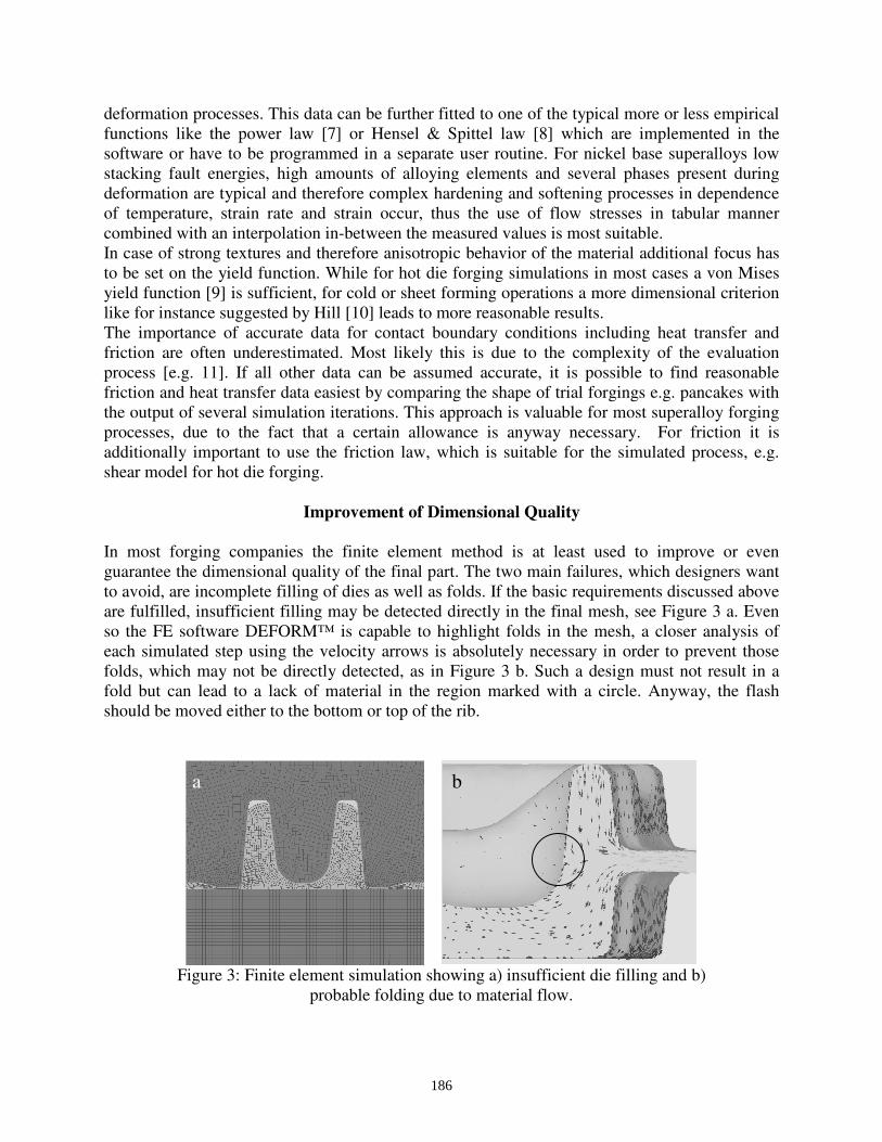
are fulfilled, insufficient filling may be detected directly in the final mesh, see Figure 3 a. Even
so the FE software DEFORM™ is capable to highlight folds in the mesh, a closer analysis of
each simulated step using the velocity arrows is absolutely necessary in order to prevent those
folds, which may not be directly detected, as in Figure 3 b. Such a design must not result in a
fold but can lead to a lack of material in the region marked with a circle. Anyway, the flash
should be moved either to the bottom or top of the rib.
Figure 3: Finite element simulation showing a) insufficient die filling and b)
probable folding due to material flow.
a b
186
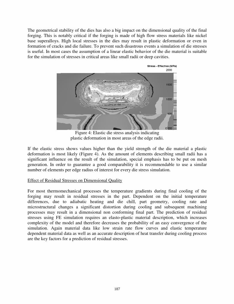
The geometrical stability of the dies has also a big impact on the dimensional quality of the final
forging. This is notably critical if the forging is made of high flow stress materials like nickel
base superalloys. High local stresses in the dies may result in plastic deformation or even in
formation of cracks and die failure. To prevent such disastrous events a simulation of die stresses
is useful. In most cases the assumption of a linear elastic behavior of the die material is suitable
for the simulation of stresses in critical areas like small radii or deep cavities.
Figure 4: Elastic die stress analysis indicating
plastic deformation in most areas of the edge radii.
If the elastic stress shows values higher than the yield strength of the die material a plastic
deformation is most likely (Figure 4). As the amount of elements describing small radii has a
significant influence on the result of the simulation, special emphasis has to be put on mesh
generation. In order to guarantee a good comparability it is recommendable to use a similar
number of elements per edge radius of interest for every die stress simulation.
Effect of Residual Stresses on Dimensional Quality
For most thermomechanical processes the temperature gradients during final cooling of the
forging may result in residual stresses in the part. Dependent on the initial temperature
differences, due to adiabatic heating and die chill, part geometry, cooling rate and
microstructural changes a significant distortion during cooling and subsequent machining
processes may result in a dimensional non conforming final part. The prediction of residual
stresses using FE simulation requires an elasto-plastic material description, which increases
complexity of the model and therefore decreases the probability of an easy convergence of the
simulation. Again material data like low strain rate flow curves and elastic temperature
dependent material data as well as an accurate description of heat transfer during cooling process
are the key factors for a prediction of residual stresses.
187
0 2 4 6 8 10 12 14-600
-400
-200
0
200
400
600
800
0 2 4 6 8 10 12 14 16
FEM - c values:
const=4000
c2=f(Time)
c3=f(Temp)
Tangential Stress
measured
Resid
ual S
tress [M
Pa]
Vertical Distance [mm]
Radial Stress
Vertical Distance [mm]
measured
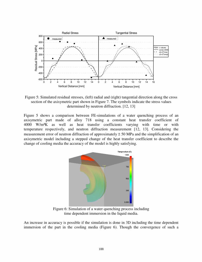
Figure 5: Simulated residual stresses, (left) radial and (right) tangential direction along the cross
section of the axisymetric part shown in Figure 7. The symbols indicate the stress values
determined by neutron diffraction. [12, 13]
Figure 5 shows a comparison between FE-simulations of a water quenching process of an
axisymetric part made of alloy 718 using a constant heat transfer coefficient of
4000 W/m²K as well as heat transfer coefficients varying with time or with
temperature respectively, and neutron diffraction measurement [12, 13]. Considering the
measurement error of neutron diffraction of approximately ± 50 MPa and the simplification of an
axisymetric model including a stepped change of the heat transfer coefficient to describe the
change of cooling media the accuracy of the model is highly satisfying.
Figure 6: Simulation of a water quenching process including
time dependent immersion in the liquid media.
An increase in accuracy is possible if the simulation is done in 3D including the time dependent
immersion of the part in the cooling media (Figure 6). Though the convergence of such a
188

problem is much weaker than the simplified 2D model the simulation time effort for the same
amount of elements in a cross section is in most cases uneconomical.
The easiest way to simulate the distortion during subsequent machining steps is to interpolate the
residual stress state of the forging on the geometry of the final part, this results in a
disequilibrium of the stress state and hence in a distortion. A higher accuracy can be achieved if
the initial mesh is manually generated, thus material removal can be simulated by deleting a
layer of elements (Figure 7). Therefore an interpolation of the stress data on a new mesh is not
necessary.
Figure 7: Simulation of the distortion after 5 machining operations (50x exaggerated) [14].
If the measured final distortion of a machined part and the simulated one show equivalent results
an accurate simulation of the residual stress state in the forging can be assumed. In Figure 8 the
distortion measurement of a 5 step turning trial of a forged and water quenched alloy 718 disc,
illustrated in Figure 7, is compared with the distortion indicated by the DEFORM2D™ elasto-
plastic simulation. The displacement along the disc radius shows good agreement between
experiment and simulation for all machining steps. Therefore machining trials together with
dimensional measurement offer an indirect method to verify residual stresses in forgings, with
the additional advantage of an easier access and less costs compared to neutron diffraction
method. Well known additional methods to verify residual stresses are the hole drilling method,
x-ray diffraction, magnetic, electric and ultrasonic methods which are all capable to measure
stresses only close to surface [15]
Figure 8: Distortion measurement and simulation of a forged and water quenched alloy 718 disc
(see Figure 7) - w indicating deflection and r the radial coordinate on the disc.
f0
f1
f2
f3
f4
f5
189
Microstructure Modeling to Optimize Forging Processes
The production of geometrically correct parts should be possible considering the above
mentioned guidelines. Obviously this may not result in a forging fulfilling all metallurgical and
mechanical requirements. Especially for nickel base superalloys a small variation in temperature
and amount of deformation may result in a significant change of the microstructure. Skilled
engineers are capable to design thermomechanical treatments within the limits of the alloy using
processing maps as published in [16]. The success of this approach is not only dependent on the
know how of the engineer but also on the number of forging and reheating operations as well as
the complexity of the alloy. The number of influencing parameters may therefore exceed the
imagination of a human mind and result in an increase of necessary forging trials. In recent years
due to the increase in computer power the development of finite element coupled microstructure
modeling has became more and more popular. The simulation of microstructural changes during
thermomechanical treatments implies the mathematical description of process relevant physical
phenomenons such as grain growth and recrystallization. In order to model these physical
processes a classification of the different phenomenons is necessary and commonly used [17,
18]. The time and deformation conditions of nucleation and growth of recrystallized grains are
parameters to distinguish the different recrystallization processes from each other. Dynamic
recrystallization is therefore defined as the process where nucleation and growth of the nuclei
happen during deformation. If the nucleation took place during the deformation and the growth
subsequently without further deformation, the recrystallization is called meta-dynamic or post-
dynamic. The third kind of recrystallization is static, which is well known where both nucleation
and growth happen after the deformation during an annealing process. Whereas dynamic and
meta-dynamic recrystallization generally lead to a refinement of the microstructure in alloys like
718, static recrystallization may result in local coarsening. [21]
190

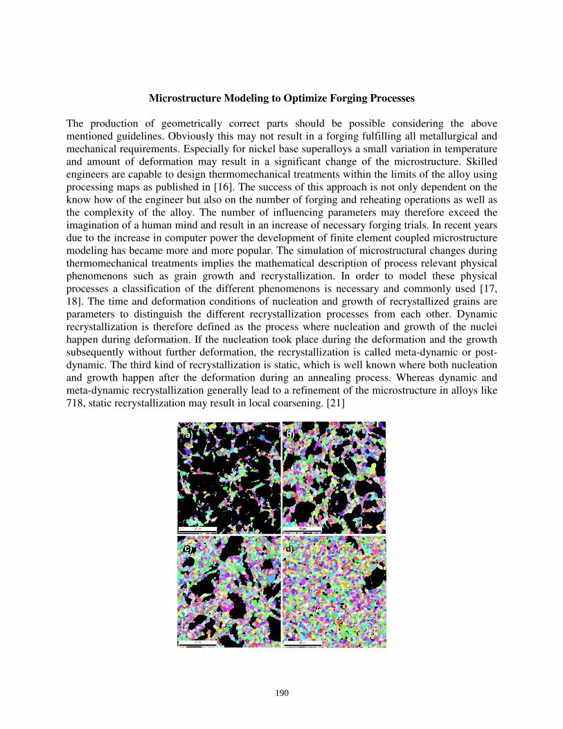
Figure 9: Progress of dynamic recrystallization at a temperature of 1000°C and a strain rate
of 1/s at strains of 0.4 (a), 0.6 (b), 0.9 (c) and 1.6 (d) based on EBSD analysis [23].
In order to calculate microstructural changes due to these physical phenomena with the finite
element method semi-empirical models with a set of material dependent parameters are
commonly coupled to standard FE codes like DEFORM™. The necessary material parameters
have to be derived from experiments like heat treatment trials, constant strain rate compression
or tensile test and quantitative microstructure analysis as illustrated in Figure 9. [e.g. 19, 20, 21]
The main advantages of such semi-empirical models compared to more physical based ones [e.g.
22] is that they usually converge very well within their limits and do not slow down the FE
simulation significantly. A verification of such a microstructure model coupled with the FE code
DEFORM2D™ is shown in Figure 10, indicating an isoline plot of the ASTM grainsize.
Figure 10: Comparison of simulation and microstructure analysis on a forged alloy 718 part.
Figure 11: Difference in ASTM grainsize in an axisymetric alloy 718 part where the blows in the
final pressing operation are varied by < 2.5% in die stroke.
191
It is also possible to test the robustness of a forging process by simulating possible variations.
Figure 11 shows that a small process variation in an alloy 718 disc forging may result in half an
ASTM grainsize difference in the final part, which may be enough to lower the desired
mechanical properties beneath the requirements.
In order to close the gap between grainsize simulation and prediction of mechanical properties of
a superalloy forging the simulation of nanostructural changes, like the precipitation of γ’
particles, is necessary. One possibility is to use the classical nucleation theory extended for
multi-component systems [24, 25] implemented in a thermo-kinetic simulation software like
MatCalc [26]. Assuming the availability of a proper thermodynamic and diffusion database
covering all chemical elements of the alloy a simulation of dissolution and precipitation of
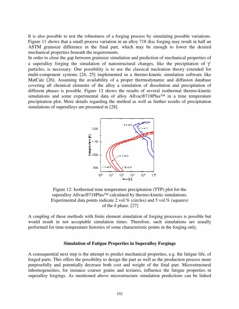
different phases is possible. Figure 12 shows the results of several isothermal thermo-kinetic
simulations and some experimental data of alloy Allvac®718Plus™ in a time temperature
precipitation plot. More details regarding the method as well as further results of precipitation
simulations of superalloys are presented in [28].
Figure 12: Isothermal time temperature precipitation (TTP) plot for the
superalloy Allvac®718Plus™ calculated by thermo-kinetic simulations.
Experimental data points indicate 2 vol.% (circles) and 5 vol.% (squares)
of the δ phase. [27]
A coupling of these methods with finite element simulation of forging processes is possible but
would result in not acceptable simulation times. Therefore, such simulations are usually
performed for time-temperature histories of some characteristic points in the forging only.
Simulation of Fatigue Properties in Superalloy Forgings
A consequential next step is the attempt to predict mechanical properties, e.g. the fatigue life, of
forged parts. This offers the possibility to design the part as well as the production process more
purposefully and potentially decrease both cost and weight of the final part. Microstructural
inhomogeneities, for instance coarser grains and textures, influence the fatigue properties in
superalloy forgings. As mentioned above microstructure simulation predictions can be linked
192

with fatigue models [29]. Comparing the lifetime behavior of four different parts regarding to the
evaluated microstructure, the maximum sustainable stress is reached by the specimen S/N-curve
of part C with highest e and lowest b, followed by part B, see Figure 13. Comparing the
microstructural damage parameters across the four forged parts, the values for part C report the
most unimodal and fine grained microstructure. Evaluating the microstructure of part D, an
increase of microstructural bimodality was detected (high b, low e), which results in a reduced
fatigue life. The microstructural parameters of specimens taken from part A show a huge
statistical spread. The same characteristic was found on the distribution of sustainable load
cycles. Additionally, it has to be taken into account that the specimens truncated from the parts
were tested at different temperatures. The microstructural evaluation model is currently refined
in order to respond the life-time behavior of alloy 718 at higher temperatures more accurately on
the one hand and to more consistently link the DEFORMTM
microstructure simulation with the
fatigue simulation on the other hand, see [30].
Figure 13: Lifetime-dependency of forged alloy 718 parts using microstructural
based damage parameters e (microstructural energy parameter)
and b (factor of heterogeneity) according to [29].
In order to use this information for a life-time prediction of final machined parts influences like
notches, operation temperature and mean stress [e.g. 30, 31] as well as surface quality, residual
stresses and type of loading have to be considered additionally. In a further step, the finite
element code is linked to an optimization tool for determining the optimum set of manufacturing
process parameters such that the component lifetime is maximized while taking process
constraints into consideration [32]. Thus, to use this approach effectively co-operations along the
supply chain are absolutely necessary, see Figure 14.
193

Componentlifetime
Lifetime modelsLifetime tests
on specimens
Forged parts
Hammer
Hydr. press
Screw press
Lifetime testson components
FE Stresses,
Load spectra
Microstructure
(+local material SN-curve at every FE node)
Fatigue Influences: notches, residual stresses, mean stress, size etc.
Virtual optimizationVerification
Componentoptimization
- Design reviews- Damage
tolerant design
Process optimiz.
- Lifetimespecifications
Thermo-mechanicalprocess (TMP) designBöhler
Component design (material,geometry, specifications)Customer
Core of multidisciplinarycomputational optimization runs
∆σ
cycles
∆σ
cycles
Fatigue analysis
Fatigue analysis input
CustomerBöhler Flowchart
Benefits
- Purpose-aimed economic production- First time right
- Neat net shape
- Lightweiht design
- Reduce life cycle costs- Reduce or shorten costly mechanical system testing
- Considering of whole simulation chain
Figure 14: Co-operations along the supply chain for a purpose-aimed component and forging
process design optimization.
Conclusion and Outlook
The fast development of computational power as well as the usability of commercial finite
element codes offer today the possibility to improve the product quality in a broad spectrum of
industrial applications. Especially for superalloy forgings, which are mainly used for critical
aircraft parts, product quality as well as production cost are natural drivers to secure the
production processes by utilizing simulation techniques. Even so residual stress and
microstructure simulations are available and used quite frequently, further improvement in order
to predict mechanical properties is necessary in future. For instance the consideration of
probabilities of impurities, segregation or coarse grains, etc. in the part and their influences on
the final properties would be a valuable extension for microstructure and life-time models.
If the simulation is to be used in the most effective way in future, a strong focus has to be set on
linking the simulation along the supply chain. Therefore special emphasis has to be put on the
definition of interfaces between the simulation methods and scales on the one hand, but on the
other hand also between customer and supplier. For simulations across different companies
specifications for the exchanged data with regard to quality and validity as well as their format
have to be defined carefully, in order to exclude misinterpretations. Even so the first steps have
been done in this direction especially in the automotive industry the way towards a real
“simulation chain” is still a long but nevertheless promising one.
194

References
1. Volker Thoms, “Fertigungstechnik I, Teil 3”, (lecture script, Institut für Formgebende
Fertigungstechnik, TU-Dresden, 2003), 13.
2. E. Siebel and S. Schwaigerer, “Zur Mechanik des Zugversuchs”, Archiv für das
Eisenhüttenwesen, 19 (1948), 145-152.
3. E. Siebel, “Kräfte und Materialfluss bei der bildsamen Formänderung”, Stahl und Eisen, 45
(1925), 1563-1566.
4. Olgierd Cecil Zienkiewicz, The finite element method in structural and continuum
mechanics, (New York, NY: McGraw-Hill, 1967).
5. Olgierd Cecil Zienkiewicz, Robert L. Taylor and J. Z. Zhu, The finite Element Method: Its
Basis and Fundamentals, (Oxford: Butterworth-Heineman – Elsevier, Ed. 6, 2006).
6. G. Li et al. “Recent development and applications of three-dimensional finite element
modeling in bulk forming processes”, Journal of Materials Processing Technology, 113
(2001), 40-45.
7. H.P. Stüwe, “Dynamische Erholung bei der Warmumformung“, Acta Metallurgica, 13
(1965), 1337-1342.
8. A. Hensel and T. Spittel, “Kraft- und Arbeitsbedarf bildsamer Formgebungsverfahren“,
(Report: VEB Deutscher Verlag für Grundstoffindustrie, 1978).
9. R. von Mises, “Mechanik der plastischen Formänderung bei Kristallen”, Zeitschrift für
Angewandte Mathematik und Mechanik, 8 (3) (1928), 161-185.
10. Rodney Hill, The Mathematical Theory of Plasticity, (Oxford: Oxford University Press, Ed.
1998).
11. B.A. Behrens et al. “Verbesserte numerische Prozesssimulation mittels eines innovativen
Reibgesetzes für die Warmmassivumformung”, Schmiede Journal, 3 (2010).
12. U. Cihak et al., “Characterization Of Residual Stresses In Compressor Discs For
Aeroengines: Neutron Diffraction And Finite Element Simulations”, Proceedings of the
Sixth International Special Emphasis Symposium on Superalloys 718, 625, 706 &
Derivatives, eds. E.A. Loria (Warrendale, PA, USA: The Minerals, Metals and Materials
Society, 2005), 517-526.
13. U. Cihak et al., “Characterization of Residual Stresses in Turbine Discs by Neutron and
High-Energy X-Ray Diffraction and Comparison to Finite Element Modeling”, Materials
Science and Engineering A, 437 (1) (2006), 75-82.
195

14. C. Krempaszky, E.A. Werner and M. Stockinger, “Measurement of macroscopic residual
stress and resulting distortion during machining”, Materials Science & Technology, 4
(2005), 109-118.
15. P.J. Withers and H.K.D.H. Bhadeshia, “Residual Stress Part 1 – Measurement
Techniques”, Materials Science and Technology, 17 (2001), 355-365.
16. Y.V.R.K. Prasad and S. Sasidhara, Hot Working Guide: A Compendium of Processing
Maps, (Ohio, OH: ASM International, (1997).
17. R.W. Cahn and P. Haasen, Physical Metallurgy, (Amsterdam: Elsevier, 1983).
18. C.M. Sellars and J.A. Whiteman, “Recrystallization and Grain Growth in Hot Rolling”,
Materials Science, 2 (1979), 187-194.
19. A.J. Brand, K. Karhausen and R. Kopp, “Microstructural Simulation of Nickel Base Alloy
Inconel 718 in Production of Turbine Discs,” Materials Science and Technology, 12
(1996), 963-969.
20. D. Huang et al., “Computer Simulation of Microstructure Evolution During Hot Forging of
Waspaloy and Nickel Alloy 718,” Proc. Microstructure Modeling and Prediction During
Thermomechanical Processing, eds. R. Srinivasan et al. (Warrendale, PA, USA: The
Minerals, Metals and Materials Society, 2001), 137-146.
21. M. Stockinger and J. Tockner, “Optimizing the Forging of Critical Aircraft Parts by the
Use of Finite Element Coupled Microstructure Modeling”, Proceedings of the Sixth
International Special Emphasis Symposium on Superalloys 718, 625, 706 & Derivatives,
eds. E.A. Loria (Warrendale, PA, USA: The Minerals, Metals and Materials Society,
2005), 87-95.
22. Ch. Sommitsch, “Theorie und Modell der mikrostrukturellen Entwicklung von Nickel-
Basis-Legierungen während dem Warmwalzen“, (Ph.D. thesis, Graz, University of
Technology, 1999).
23. D. Huber et al., “Microstructure modeling of the dynamic recrystallization kinetic during
turbine disc forging of the nickel based superalloy Allvac 718 Plus™”, Proc. of the 11th
International Symposium on Superalloys 2008, eds. R.C. Reed, K.A. Green, P. Caron, T.P.
Gabb, and M.G. Fahrmann, (Warrendale, PA, USA: The Minerals, Metals and Materials
Society, 2008), 855-861.
24. J. Svoboda et al., “Modelling of Kinetics in Multi-Component Multi-Phase Systems with
Spherical Precipitates I: Theory”, Materials Science & Engineering A, 385 (2004) 166-174.
25. K.G.F. Janssens, D. Raabe, E. Kozeschnik, M.A. Miodownik and B. Nestler,
Computational Materials Engineering – An Introduction to Microstructure Evolution,
(Oxford, UK: Elsevier Academic Press, 2007).
196

26. E. Kozeschnik et al., “Modelling of Kinetics in Multi-Component Multi-Phase Systems
with Spherical Precipitates II: Numerical Solution and Application”, Materials Science &
Engineering A, 385 (2004) 157-165.
27. G.A. Zickler et al., “The precipitation behavior of superalloy ATI Allvac®718Plus™”,
Advanced Engineering Materials, 12 (3) (2010), 176-183.
28. R. Radis et al., “Numerical Simulation of the Simultaneous Precipitation of d and g’ Phases
in the Ni-Base Superalloy ATI Allvac®718Plus™”, accepted for Proceedings of the
Seventh International Special Emphasis Symposium on Superalloys 718, 625, 706 &
Derivatives, (Warrendale, PA, USA: The Minerals, Metals and Materials Society, 2010).
29. M. Stoschka et al., “Assessment of Lifetime Calculation of Forged IN718 Aerospace
Components Based on a Multi-parametric Microstructural Evaluation”, Proc. of the 11th
International Symposium on Superalloys 2008, eds. R.C. Reed, K.A. Green, P. Caron, T.P.
Gabb, and M.G. Fahrmann, (Warrendale, PA, USA: The Minerals, Metals and Materials
Society, 2008), 573-582.
30. M. Maderbacher et al., “Lifetime Evaluation of Hot Forged Aerospace Components by
Linking Microstructural Evolution and Fatigue Behaviour”, accepted for Proceedings of
the 10th
International Fatigue Congress, (2010).
31. M. Stoscka et al., “Einfluss der Warmformgebung auf die Schwingfestigkeit”, Proceedings
of the 1st Leobener Betriebsfestigkeitstage, eds. W. Eichlseder (Leoben, Austria: Institute of
Mechanical Engineering, 2006), 117-132.
32. H. Maderbacher et al., “Lifetime Optimization of Hot Forged Aerospace Components by
Linking Microstructural Evolution and Fatigue Behaviour”, accepted for The European
Symposium on Superalloys and their Application, (http://www.scientific.net/, 2010).
197