effect of pile- soil- structure interaction on dynamic characteristic of
TRANSCRIPT
The 2012 World Congress on Advances in Civil, Environmental, and Materials Research (ACEM’ 12)Seoul, Korea, August 26-30, 2012
Effect of Pile- Soil- Structure Interaction on Dynamic Characteristic of Sample Jacket Type Offshore Platform by Experimental and
Numerical Investigation
Behrouz Asgarian1a, Hamed Rahman Shokrgozar2, Davoud Shahcheraghi3, Hasan Ghasemzadeh4
1) Associate Professor, Civil Engineering Faculty, K.N.Toosi University of Technology, Tehran, Iran
2) PhD Student in Structure Engineering, Civil Engineering Faculty, K.N.Toosi University of Technology, Tehran, Iran
3) Msc in Marine Structures, Civil Engineering Faculty, K.N.Toosi University of Technology, Tehran, Iran
4) Assistant Professor, Civil Engineering Faculty, K.N.Toosi University of Technology, Tehran, Iran
Abstract. Dynamic response of Pile Supported Structures is highly depended on the Pile Soil Structure Interaction. In this paper, by comparison of experimental and numerical dynamic response of a prototype jacket type offshore platform for both hinge based and pile supported boundary conditions, effect of soil-pile-structure interaction is studied. Jacket and deck of a prototype platform is installed on a hinge-based case first and then platform is installed on eight skirt piles embedded on continuum monolayer sand. Dynamic characteristics of both cases of platform in term of natural frequencies, mode shapes and modal damping are computed and compared with the others. Numerical simulation of responses for the studied structure is also performed for both cases using capability of ABAQUS and SACS software. The 3D model of ABAQUS is created using continuum elements for soil and piles, and beam elements for jacket and deck elements. Mohr-Coulomb model and pile-soil contact theory are used for considering nonlinear inelastic soil properties. Simplified modeling of soil-pile-structure interaction is also studied using SACS software. It is observed that dynamic characteristics of the system changes significantly due to soil-pile-structure interaction. Meanwhile, both of complex and simplified (ABAQUS and SACS) models can predict this effect accurately for the studied platform in small range of deformation. Keywords: Steel Jacket type Offshore Platform: Soil-Pile-Structure Interaction: Experimental Modal Analysis; Finite element. 1. Introduction
Pile foundations are a part of many structures such as jacket type offshore platforms used to transfer loads from superstructure to the soil layer. When external forces such as earthquake, wind or wave act on pile-supported structures, structural, soil and pile displacements are independent of the others. Response of the soil-pile influences the motion of the structure, and the motion of the structure influences the response of the soil-pile, which is termed as soil-pile-structure interaction (SPSI). The effects of SPSI are prominent for pile-

supported structures such as heavy structures resting on soft soils, high-rise buildings and jacket type offshore platforms. SPSI has an important effect in analysis result of jacket type offshore platforms. Meanwhile, dynamic characteristic and response of such a structure is highly depended to dynamic pile-soil structure interaction.
There are considerable researches on dynamic soil–pile–structure interaction (Mizuno 1987). Some procedures have been developed for considering this effect in evaluating of the dynamic response of steel jacket platforms. The simplified double-step method in which uncouples superstructure and pile systems portions is the first and less complex method. In this methods beam elements are used for the modeling of jacket, deck and pile members and soil media is discretized to parallel springs trying to represent soil real behavior. Two and three-dimensional continuum modeling of the pile and surrounding soil by using finite-element or finite-difference approaches is more complex and high computational demands method presented by many researchers (Wu and Finn 1997 and Cai et al. 2000).
In the first category, dynamic beam on a nonlinear Winkler foundation model was used by Nogami (1992) to analysis dynamic response of pile foundations in time domain space. El Naggar (1992) and Novak (1995) presented a nonlinear analysis for pile groups in time domain space within the framework of the Winkler hypothesis. Wang et al. (1998) compared several implementations of the dynamic p-y method and showed that calculations can be sensitive to the details of the nonlinear springs and dashpots. These approaches can be performed by using available computer codes.
In this paper, effect of soil-pile structure interaction on dynamic characteristic of a prototype sample offshore platform is investigated through experimental and numerical studies. For this purpose, a prototype model of a sample steel jacket type offshore platform with a scale factor of 1:15 is fabricated as welded-steel space frame. Dynamic test of platform SP (sample platform) is conducted for two hinge-based and pile-supported conditions. The platform is installed first on strong rigid floor of the laboratory and it is tested as hinge based support condition, then the platform is removed and installed on eight skirt piles and it is tested as pile-supported condition. By comparison of dynamic characteristics platform in both cases, effect of soil pile structure interaction on dynamic characteristics of the platform is investigated.
Numerical dynamic analysis of the model is also performed using two common models of soil-pile-structure interaction modeling techniques. Continuum three-dimensional modeling of pile and surrounding soil is performed using ABAQUS finite-element software. In this model, the interaction between soil and pile is considered using contact elements. Then, the two-step method is considered using SACS software. P-y, T-z and Q-z nonlinear springs, according to the API RP-2A (2000) are modeled to simulate the soil-pile interaction. As SACS is commonly used in offshore engineering applications, it is selected for the simplified modeling of pile and surrounding soil.
2.Identification of the Dynamic Characteristics
Earthquake response of any structure comes from some sources: observations made from the structural response during last earthquakes, experiments conducted on reduced scaled or actual size models of the structures and finally from analytical or numerical study. Performing experimental investigation is unavoidable issue in complex structure such as offshore platforms to verify the numerical result. The use of experimental techniques has been

widely applied to detect dynamic behavior of structural systems subjected to dynamic. These techniques are being investigated in several fields, such as mechanical engineering (Ziebath, and Baumgartner, 1981, James et al, 1994), aircraft testing (Shelleye et al, 1993), aerospace applications (JamesI II et al, 1998) and the offshore industry (Vandiver, 1975, Hamamoto and Kondo, 1993, Ruotolo et al, 2000).
Performing tests using dynamic measurement offers the opportunity to obtain information about the whole system based on small number of measurements. Usually, these tests are based on determining system vibration response and relating it to the modal properties. Experimental modal analysis is the term used for determining the modal properties of a system experimentally. In many cases, the modal properties consist of the modal frequency, mode shape and modal damping. Two very common methods of the structural modal testing are the force vibration and ambient vibration (Salawu and Williams 1995). In ambient vibration tests, the excitation is not under the control and is usually considered as a stationary random process, which means that response data from the structure alone can be used to estimate the dynamic parameters. Ambient excitation can be from sources such as wind, pedestrian or vehicular traffic, earthquakes, waves or similar. For very large and massive structures, ambient excitation is often the only practical choice. Structural identification through ambient vibrations has been successful in numerous cases (Ivanovic, et al. 2000; Ventura, et al. 2003).
In case of the forced vibration testing, the input excitation to the structure is provided by properly designed excitation systems, which entails application of a known force at particular frequencies or frequency bands of interest (Causevic 1987; De Sortis, et al. 2005). This method is based on the fact that if loading on the structure and resulting responses are known, then the structural characteristics can be more unambiguously determined. These types of tests also have the advantage of the achieving larger signal to noise ratios in the response measurements (Salawu and Williams 1995).
The need for testing the behavior of full-scale structures under dynamic loads and studying the modified structural system cannot be implemented due to its complexity and operation. Fabricating the laboratory scale model of the structure is one of the alternative methods to comparison and investigation of the performance of existing and new systems.
2.1. Description of Scaled Model
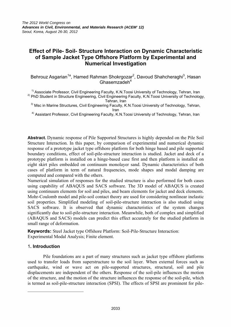
Scaled model of a newly installed jacket type offshore platform in Persian Gulf SP1 is considered for this study. The laboratory model is a welded-steel space frame with six legs, horizontal and vertical braces, two-story decks and eight skirt piles. The details of the model are presented in Figure 1. Due to available pipes and laboratory facilities, the geometric scale used is 1:15. The legs had a diameter of 48 mm and a wall thickness of 3 mm. All horizontal bracing was 34 mm in diameter and 3 mm thick. The deck is consisted of intersectional beams with box section (60×40×3 mm). A plate with a thickness of 15 mm is welded to deck beam in order to simulate rigid diaphragm action and topside weight. For considering joint cans in jacket, the thickness of legs is increased to 5 mm. Eight skirt sleeves with 88.9 mm in diameter and 5 mm thickness is connected to the legs. Totally 4 sample of pipes is tested. One sample is tested for each size of used pipes. The modulus of elasticity and yield stress of steel piles are determined as 2x10⁸ KN/m2 and between 265-285 MN/m2 (respectively).
The 3D frames were constructed by qualified fitters and welders who all is engaged
and quitminimizspecify tubular tested utests, anfailure.
2.1.1.B
te experiencze initial ecclose fit-umember co
under PT (liqnd the repa
Boundary C
Jacket type
ced in real-sccentricitiesup of weldeonnections. quid penetrairs are don
Figu
Condition
e offshore p
scale jackets, bevel the ed componeThe weldinate examina
ne to detect
ure 1. Elev
ns in Expe
platforms a
t fabricationends of m
ents and ung is done uation) and Mt and remo
ation of the s
riment
are connecte
n. Care is taembers simse the full
under the CoMT (magnetve the flaw
scaled mode
ed to seabed
ken to insurmilar to API
penetrationo2 shieldingtic particle
ws that coul
l SP1
d by piles f
re proper alI recommenn butt weldg gas. All wexaminatio
uld cause pr
foundation
lignment, ndations, ds at all
welds are n), NDT remature
with the
sufficient penetration in soil to resist lateral and vertical loads is a safe manner. The effect of soil-pile interaction in the response of structure subjected to external forces is an important issue. In this paper the effect of soil-pile-Structure interaction on dynamic characteristic of a prototype offshore platform is investigated by comparison of experimental and numerical results of platform responses for two boundary condition cases. Firstly forced vibration tests are performed for the platform installed on rigid floor of laboratory as hinged base condition. For this purpose, four corner leg of the platform is connected to floor beam by a short stub (20 cm length) through four bolts for each leg.
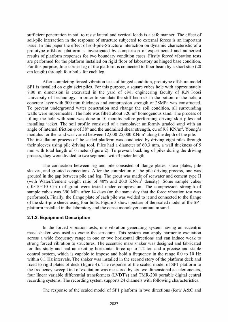
After completing forced vibration tests of hinged condition, prototype offshore model SP1 is installed on eight skirt piles. For this purpose, a square cubes hole with approximately 7.00 m dimension is excavated in the yard of civil engineering faculty of K.N.Toosi University of Technology. In order to simulate the stiff bedrock in the bottom of the hole, a concrete layer with 500 mm thickness and compression strength of 28MPa was constructed. To prevent underground water penetration and change the soil condition, all surrounding walls were impermeable. The hole was filled about 320 m3 homogenous sand. The process of filling the hole with sand was done in 10 months before performing driving skirt piles and installing jacket. The soil profile consisted of a monolayer uniformly graded sand with an angle of internal friction φ of 38° and the undrained shear strength, cu of 9.8 KN/m2. Young’s modulus for the sand was varied between 12,000-25,000 KN/m2 along the depth of the pile. The installation process of the scaled platform was conducted by driving eight piles through their sleeves using pile driving tool. Piles had a diameter of 60.3 mm, a wall thickness of 5 mm with total length of 6 meter (figure 2). To prevent buckling of piles during the driving process, they were divided to two segments with 3 meter length.
The connection between leg and pile consisted of flange plates, shear plates, pile sleeves, and grouted connections. After the completion of the pile driving process, one was grouted in the gap between pile and leg. The grout was made of seawater and cement type II (with Water/Cement weight ratio of 40% and 20.0 KN/m3 density). Some sample cubes (10×10×10 Cm3) of grout were tested under compression. The compression strength of sample cubes was 390 MPa after 14 days (on the same day that the force vibration test was performed). Finally, the flange plate of each pile was welded to it and connected to the flange of the skirt-pile sleeve using four bolts. Figure 3 shows picture of the scaled model of the SP1 platform installed in the laboratory and the dense monolayer continuum sand.
2.1.2. Equipment Description
In the forced vibration tests, one vibration generating system having an eccentric mass shaker was used to excite the structure. This system can apply harmonic excitation across a wide frequency range in one or two horizontal directions and can induce weak to strong forced vibration to structures. The eccentric mass shaker was designed and fabricated for this study and had an exciting horizontal force up to 1.2 ton and a precise and stable control system, which is capable to impose and hold a frequency in the range 0.0 to 10 Hz within 0.1 Hz intervals. The shaker was installed in the second story of the platform deck and fixed to rigid plates of deck (figure 4). The response of the scaled model of SP1 platform to the frequency sweep kind of excitation was measured by six two dimensional accelerometers, four linear variable differential transformers (LVDT's) and TMR-200 portable digital central recording systems. The recording system supports 24 channels with following characteristics.
The response of the scaled model of SP1 platform in two directions (Row A&C and
Row1&increasiapproxitexting evaluateresonanaccelero
&2) was meing the inpumate modaprogram th
ed. In thesent frequencieometers.
Figur
easured in ut frequenc
al frequencyhe exact vale stages, thees by a 0.1H
re 2. sketch
several stacy from 1 Hy values wlue of nature frequencyHz interval
of scaled mo
ages. The fHz to 4 H
were evaluatral frequenc
y of excitatils and the re
odel, SP1, on
first stage oz by 0.2 Hted. In the cies and coion was incesponse of
n soil-pile sup
of the test Hz intervals
next stage rresponding
creased arouthe platform
pported cond
was condus. In this ste of force vg mode shaund the prem was meas
dition.
ucted by tage, the vibration apes was liminary sured by

Figure 3. Installation of scaled model, SP1, on Hinge Support and soil-pile supported condition.
Figure 4. Eccentric mass shaker
2.2. Numerical Modeling Description
Dynamic characteristics of the scaled platform SP1 is also computed numerically using modeling capability of ABAQUS and SACS finite-element software. For three-dimensional modeling of the soil media, piles and superstructure elements, and also considering direct interaction between soil-pile-structure, finite-element ABAQUS software is used. The common and less complex method that used in many offshore engineering applications is used by modeling capability of SACS software.

2.2.1. Modeling in ABAQUS
Finite-element code ABAQUS is used in this study for the numerical modeling of scaled offshore platform SP. The superstructure elements, including legs, vertical and horizontal bracing members and deck beams are modeled using nonlinear two nodes beam elements. Three dimensional solid elements are applied to model piles and soil media. Mohr-Coulomb geotechnical constructive model is assumed for modeling soil material behavior.
The soil-pile interfaces are assumed as a frictional interface where soil-pile slipping and gapping may occur. Generally, Coulomb’s law of friction is used to model slipping and gapping in the soil and pile. If interface surface is in contact, full transfer of shear stress is ensured and separation will occur when there is tension between the soil and pile interface. Thus in ABAQUS, the contact constraint is applied between two surfaces of pile and soil. The surfaces separate when the contact pressure between them becomes zero or negative, and the constraint is removed. This behavior, referred to as hard contact. Because the system is subjected to a small force which does not induce slip, for the tangential component, rough interaction is assumed between surfaces.
2.2.2. Modeling in SACS
In present, SACS software is widely used in practice for modeling soil-pile interaction in both research and professional jobs because it is simple and conceptual definitude. In the software, the pile and surrounding soil are divided into a number of discrete layers. Pile is simulated by Beam element, and its response is traced independently at nodal points of the pile segments within each layer. The stiffness and mass of the pile segments are established at these nodes. Soil resistance is assessed at each node and represented as a non-linear spring. In the present study, the p-y, t-z and q-z curves are used for considering the soil stiffness. The procedures for generating these curves are recommended by the American Petroleum Institute (API-RP-2a, 2000). Some tests are conducted at various deep of soil for calculating the p-y, t-z and q-z curves. 3.Result and Analysis of the Experimental Recorded Data
In this section, the result of experimental and numerical analyses are presented in the term of modal characteristics. Force vibration tests of scaled model of platform are performed and response of system to excitation is derived. To identification of the modal characteristics of the scaled platform SP1, signal processing method was used based on the power spectral density function. Modal frequencies and mode shapes are also obtained numerically using SACS and ABAQUS outputs. 3.1.Estimation of Natural Frequencies
The natural frequency of the scaled platform, SP is calculated using power spectral density (PSD), Equation 1, cross correlation spectrum (CPS), Equation 2, phase relationship, Equation 3, and the Coherence Spectrum (CS), Equation 4. The CPS, phase relationship and CS are estimated between all response measurement points and one reference point. The segment averaging method (also known as Welch’s method) was used for better correlation and minimizing errors. The method consists of dividing time-series data into (possibly overlapping) segments, computing a modified spectrum of each segment, and then averaging the PSD and CPS estimates. Therefore, PSD and CPS are estimated by dividing each acceleration data to eight segments and using a Hanning window with 50% overlap.

To distinguish the spectral peaks representing the platform vibration modes from those corresponding to peaks in the input spectrum, the advantage concurrency of the CPS peak and the orthogonality condition of mode shapes are used. That is, all points of the platform in a lightly damped mode of vibration are in-phase or 1800 out- phase with each other, depending only on the shape of the normal mode. Moreover, the large amount (approximately 1) must be occurred in the value of the coherence spectrum at the candidate frequency. A MATLAB subroutine is coded for this aim.
∫+∞
∞−
τπ− ττ= deRfSPSD fjxxxx
2)()(: (1)
∫+∞
∞−
τπ− ττ= deRfSCPS fjxyxy
2)()(: (2)
)()()( fjQfCfS xyxyxy −= (3)
⎥⎥⎦
⎤
⎢⎢⎣
⎡=θ −
)()()(
21
fCfQtgf
xy
xyxy (4)
)()()(
:2
2
fSfSfS
CSyyxx
xyxy =γ (5)
In the above equation Sxx and Rxx are respectively power spectral density and the auto-correlation of a measurement point of the structure. Sxy and Rxy are respectively the cross correlation spectrum and the cross-correlation between two response measurement points of the structure. The cross correlation spectrum, Sxy is a complex value that is shown by the real value, Cxy and imaginary value, Qxy. The phase spectrum of the CPS is calculated from Equation 2 and detect that the two-point of vibrations (X and Y) is in-phase or out-phase. The degree of linear association between two signals is compared by ordinary coherence function. Two signals are completely correlated, and its function is shown unity value, if there is not any noise during the vibration recording and also, there is not any computational error in the spectral calculation. The coherence spectrum has a peak in the resonant frequency of the platform, and its value is larger than 0.5.
Two typical signal processing output for the force excitation in the Row A&C direction with the constant frequency, 2.7 Hz, are presented figure 5. The figure 5-a is shown the recorded acceleration No. 1 and 2, and in the figure 5-b, the above method is executed for these two accelerations that installed at the top of the jacket of the scaled platform.
Tables 1 and 2 present natural frequencies of the scaled model platform with hinge based supports and pile supported condition respectively. The ratio of natural frequency changes in both cases (Hinge based and pile supported) of scaled platform illustrated in table 3. By comparing the natural frequency of the scaled platform at two boundary condition cases, it is observed soil-pile-structure interaction decreases natural frequencies of different modes. Meanwhile, it has significant decrease on second mode of each direction. In addition ABAQUS and SACS software can predict natural frequency of such a system accurately. ABAQUS model is more complex model compared to SACS model which is a simplified one.

(a)
(b)
Figure 5. (a) the recorded Acceleration in Row A&C direction for Acceleration No. 1 & 2. (b) respectively, power spectral density of Accel. No.1 & No. 2, cross spectral density between Accel. No. 1 & No. 2, coherence spectrum between Accel. No. 1 & No. 2 and phase spectrum between Accel. No.
1 & No. 2. Table 1. Natural Frequency of Scaled model platform with the hinge based case
Test ABQUS Software SACS Software
M.1 M.2 M.1 M.2 Error M.1 %
Error M.2 % M.1 M.2 Error
M.1 % Error M.2 %
Row A&C 3.1 20.32 3.20 20.07 3.42 -1.20 3.27 21.06 5.62 3.64 Row 1&2 3.24 19.69 3.44 19.49 6.23 -0.97 3.41 20.57 5.18 4.47 Torsion 6.15 24.86 5.87 24.73 -4.61 -0.5 5.01 26.11 -18.56 5.03
Table 2. Measured Natural Frequency of the platform for pile supported case
Test ABQUS Software SACS Software
M.1 M.2 M.1 M.2 Error M.1 %
Error M.2 % M.1 M.2 Error
M.1 % Error M.2 %
Row A&C 2.75 11.02 2.95 12.03 6.97 9.24 2.99 13.78 8.64 25.12 Row 1&2 2.89 11.78 3.10 12.12 7.30 2.91 3.07 13.88 6.18 17.86 Torsion 5.49 13.93 5.64 14.25 2.68 2.36 5.70 14.30 3.86 2.69
-4.0
-2.0
0.0
2.0
4.0
6.0
8.0
0.0 20.0 40.0 60.0 80.0 100.0 120.0
A (m
/s2 )
Accel-T1-1
-6.0-4.0-2.00.02.04.06.0
0.0 20.0 40.0 60.0 80.0 100.0 120.0Time (sec)
A (m
/s2 ) Accel-T2-1
0.020.040.060.0
0.0 3.0 6.0 9.0 12.0 15.0 18.0 21.0 24.0 27.0
PSD- Accel.1
0.00
2.00
4.00
0.0 3.0 6.0 9.0 12.0 15.0 18.0 21.0 24.0 27.0
PSD- Accel.2
0.05.0
10.015.0
0.0 3.0 6.0 9.0 12.0 15.0 18.0 21.0 24.0 27.0
CPS- Accel.1 & Accel.2
0.000.501.001.50
0.0 3.0 6.0 9.0 12.0 15.0 18.0 21.0 24.0 27.0
CS- Accel.1 & Accel.2
-4.0-2.00.02.04.0
0.0 3.0 6.0 9.0 12.0 15.0 18.0 21.0 24.0 27.0Frequency (Hz)
Phase angle- Accel.1 & Accel.2
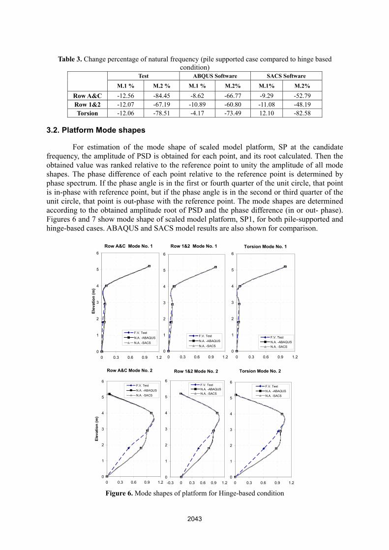
Table 3. Change percentage of natural frequency (pile supported case compared to hinge based condition)
Test ABQUS Software SACS Software
M.1 % M.2 % M.1 % M.2% M.1% M.2%
Row A&C -12.56 -84.45 -8.62 -66.77 -9.29 -52.79 Row 1&2 -12.07 -67.19 -10.89 -60.80 -11.08 -48.19 Torsion -12.06 -78.51 -4.17 -73.49 12.10 -82.58
3.2. Platform Mode shapes
For estimation of the mode shape of scaled model platform, SP at the candidate frequency, the amplitude of PSD is obtained for each point, and its root calculated. Then the obtained value was ranked relative to the reference point to unity the amplitude of all mode shapes. The phase difference of each point relative to the reference point is determined by phase spectrum. If the phase angle is in the first or fourth quarter of the unit circle, that point is in-phase with reference point, but if the phase angle is in the second or third quarter of the unit circle, that point is out-phase with the reference point. The mode shapes are determined according to the obtained amplitude root of PSD and the phase difference (in or out- phase). Figures 6 and 7 show mode shape of scaled model platform, SP1, for both pile-supported and hinge-based cases. ABAQUS and SACS model results are also shown for comparison.
Figure 6. Mode shapes of platform for Hinge-based condition
Row A&C Mode No. 1
0
1
2
3
4
5
6
0 0.3 0.6 0.9 1.2
Elev
atio
n (m
)
F.V. TestN.A. -ABAQUSN.A. -SACS
Row 1&2 Mode No. 1
0
1
2
3
4
5
6
0 0.3 0.6 0.9 1.2
F.V. TestN.A. -ABAQUSN.A. -SACS
Torsion Mode No. 1
0
1
2
3
4
5
6
0 0.3 0.6 0.9 1.2
F.V. TestN.A. -ABAQUSN.A. -SACS
Row A&C Mode No. 2
0
1
2
3
4
5
6
0 0.3 0.6 0.9 1.2
Elev
atio
n (m
)
F.V. TestN.A. -ABAQUSN.A. -SACS
Row 1&2 Mode No. 2
0
1
2
3
4
5
6
-0.3 0 0.3 0.6 0.9 1.2
F.V. TestN.A. -ABAQUSN.A. -SACS
Torsion Mode No. 2
0
1
2
3
4
5
6
0 0.3 0.6 0.9 1.2
F.V. TestN.A. -ABAQUSN.A. -SACS

Figure 7. Mode shapes of platform for pile supported condition
By comparing the mode shape of the scaled platform at two boundary condition cases, it is observed soil pile structure interaction decreases the stiffness of structure and increases the lateral relative displacement of the jacket. It can be observed that the first mode shape of scaled platform at soil pile supporting condition to the hinge base is changed slightly. Nevertheless, the effect of soil pile support is illustrated at the higher mode shapes. In addition, both of ABAQUS and SACS software’s estimated first mode shape of scaled model, SP1, more accurately than the second mode shape.
3.3. Estimation of Modal Damping
Half-power bandwidth method is used for calculating the modal damping. The damping ratio is calculated using equation 6 in which frequencies fa and fb are illustrated in figure 8. Table 4 shows damping ratio for different modes of both boundary condition cases.
ab
ab
ffff
+−=ζ (6)
Row A&C Mode No. 1
0
1
2
3
4
5
6
0 0.3 0.6 0.9 1.2
Elev
atio
n (m
)
F.V. TestN.A. -ABAQUSN.A. -SACS
Row 1&2 Mode No. 1
0
1
2
3
4
5
6
0 0.3 0.6 0.9 1.2
F.V. TestN.A. -ABAQUSN.A. -SACS
Torsion Mode No. 1
0
0.2
0.4
0.6
0.8
1
1.2
0 0.3 0.6 0.9 1.2
F.V. TestN.A. -ABAQUSN.A. -SACS
Row A&C Mode No. 2
0
1
2
3
4
5
6
-0.3 0 0.3 0.6 0.9 1.2
Elev
atio
n (m
)
F.V. TestN.A. -ABAQUSN.A. -SACS
Row 1&2 Mode No. 2
0
1
2
3
4
5
6
-0.3 0 0.3 0.6 0.9 1.2
F.V. TestN.A. -ABAQUSN.A. -SACS
Torsion Mode No. 2
0
0.2
0.4
0.6
0.8
1
1.2
0 0.3 0.6 0.9 1.2
F.V. TestN.A. -ABAQUSN.A. -SACS

compare(naturalhigher m
4. Con
platformthe strubase suforce vimodal pnumericsoftwaredecreasemodal pshapes athan theSACS aexperimit result
It can be sed to hingl frequency modes is so
clusion
In this papm is studieducture laboraupporting coibration dynproperties, scal modeline. The resue the naturproperties, aand modal e first modeand ABAQ
mental results is more ac
Fig
Table 4. M
Row A&C Row 1&2 Torsion
een that gene based coand mode significantl
per, dynamid using expatory and thondition fornamic test issignal proceng of samplult of experiral frequencand considedamping. Te for all the
QUS softwarts. Due to thccurately th
ure 8. Typic
Modal Dampi
Hinge BaseM.1
0.012110.013890.00586
nerally equiondition. Si
shape) the ly than the f
c characteriperimental ahe soil-pile r investigats conductedessing is usele platformimental anacy of structering SPSI iThe effectse dynamic cre, SP1, at he complexian the SAC
cal frequency
ing for both b
ed ConditionM.2
0.002910.002000.00171
ivalent damimilar to th
effect of sfirst mode.
ristics of a sand numeric supportingtion the effd at each suped based on
m, SP1, arealysis is shoture. The sis increasedof SPSI arecharacteristfirst mode
ity of modeCS software
y response cu
boundary co
Pile SuppoM.1
1 0.013240 0.016891 0.00819
mping increahe previousoil pile sup
scaled modecal studies.
g with monofect of soil-pporting conn the powere performedown that theame result
d the relative significanics. The nu
e to secondelling in AB.
urve.
ndition cases
orted ConditioM.2
0.004090.004160.00287
ases in the ps modal chpport to the
el of steel jThe simula
olayer soil -pile-structundition, andr spectral ded using ABe soil-pile-sis also obs
e lateral disntly illustratumerical res
mode is aBAQUS soft
s
on
9 6 7
pile supportharacteristice modal dam
jacket type ated hinge are conside
ure interactid to identificensity functBAQUS anstructure intserved in thsplacement ted at highesults obtainea better mattware, in mo
ted cases s’ result
mping at
offshore bases at
ered as a ion. The cation of tion. The d SACS teraction he other at mode
er modes ed using tch with ost cases,

Acknowledgement
The research employed herein was sponsored under POGC (Pars Oil and Gas Company) project No. 132 “Investigation of Structural Health Monitoring of Steel Jacket Offshore Platforms”. The financial support of POGC is gratefully acknowledged. *a Corresponding author, E-mail: [email protected] References Abaqus Inc., Pawtucket, RI, Abaqus Analysis User’s manual, 2010, Version 6.8-2 American Petroleum Institute, Recommended practice for planning, designing and constructing fixed offshore platforms (2000). API Recommended Practice 2A (RP-2A), 21st ed. American Petroleum Institute, Washington, D.C. Bentley KJ, El Naggar MH., (2000) “Numerical analysis of kinematics response of single piles’’, Can Geotech J;37, 1368–1382. Cai YX, Gould PL, Desai CS., (2000) ‘‘Nonlinear analysis of 3D seismic interaction of soil–pile-structure system and application’’, Engng Struct, 22(2), 191–9. Causevic, M. S., (1987) ‘‘Mathematical modelling and full-scale forced vibration testing of a reinforced concrete structure’’, Engineering Structures, 9(1): 2-8 De Sortis, A., et al. (2005) ‘‘Dynamic identification of a masonry building using forced vibration tests’’, Engineering Structures, 27(2), 155-165. El Naggar MH, Novak M. (1996) ‘‘Nonlinear analysis for dynamic lateral pile response’’, Soil Dyn Earthquake Engng,15, 233–44. El Naggar MH, Novak M., (1995) ‘‘Nonlinear lateral interaction in pile dynamics’’, Soil Dyn Earthquake Engng,14, 141–57. Hamamoto, T. and Kondo, 1. (1993) ‘‘Preliminary experiments for damage detection of offshore structures’’, Proceedings of the Third International Offshore and Polar Engineering Conference, 685-692. Ivanovic, S. S., et al. (2000). ‘‘Ambient vibration tests of a seven-story reinforced concrete building in Van Nuys, California, damaged by the 1994 Northridge earthquake’’, Soil Dynamics and Earthquake Engineering 19(6): 391-411. James III, G. H., Zimmerman, D. C. and Mayes, R. L. (1998) ‘‘Experimental study of Frequency Response Function (FRF) based damage assessment tools’’, Proceedings of the Sixteenth International Modal Analysis Conference, James, G., Mayes, R., Came, T. and Reese, G. (1994) ‘‘Damage detection and health monitoring of operational structure’’, Proceedings of the 1994 international Mechanical Engineering Congress and Exposition, 371-380 Mizuno H. (1987) “Pile damage during earthquake in Japan (1923-1983).” Dynamic response of Pile Foundations, Geotech. Special Publ. No: 11, ASCE, 53-78. Nogami T, Konagai K. (1986) ‘‘Time domain axial response of dynamically loaded single piles’’, J Engng Mech ASCE, 112(11), 1241–52. Nogami T, Konagai K. (1988) ‘‘Time domain flexural response of dynamically loaded single piles’’, J Engng Mech ASCE, 114(9), 1512–25. Nogami T, Otani J, Konagai K, Chen HL. (1992) ‘‘Nonlinear soil–pile interaction model for dynamic lateral motion’’, J Geotech Engng ASCE, 118(1), 89–106. Ruotolo, R., Surace, C. and Worden, K. (2000) ‘‘Application of two damage detection techniques to an offshore platform’’, Shock and Vibration Digest, Vol. 32, No. 1, 30-31 Salawu, O. S. and C. Williams (1995) ‘‘Review of full-scale dynamic testing of bridge structures”, Engineering Structures 17(2): 113-121. Shelley, S. J., Freudinger, L. C. and Allemang, R. J. (1993) ‘‘Development of an on-line modal state monitor", Proceedings of the Eleventh International Modal Analysis Conference Volume 2, l581-1586. Vandiver, J. HK. (1975) ‘‘Detection of structural failure of fixed platforms by measurement of dynamic response’’, Journal of Petroleum Technology, 305-31.

Ventura, C. E., et al. (2003) ‘‘Dynamic characteristics of a base isolated building from ambient vibration measurements and low level earthquake shaking”, Soil Dynamics and Earthquake Engineering 23(4), 313-322. Wang, S., Kutter, B. L., Chacko, M. J., Wilson, D. W., Boulanger, R. W. and Abghari, A. (1998). ‘‘Nonlinear seismic soil-pile structure interaction”. Earthquake Spectra, 14(2), 377-396. Wu, G. and Finn, W. D. L. (1997) ‘‘Dynamic nonlinear analysis of pile foundations using finite element method in the time domain”, Canadian Geotechnical Journal, 34, 44-52. Ziebarth, H. and Baumgartner, R. J. (1981) ‘‘Early detection of cross-sectional rotor cracks by turbine shaft vibration monitoring techniques’’, American Society of Mechanical Engineers, ASME, paper 81-JPGC-Pwr-26.