effect of nano rubber additions on wear and mechanical properties of epoxy glass fibre composites
TRANSCRIPT
International Journal of Recent Research in Civil and Mechanical Engineering (IJRRCME) Vol. 1, Issue 1, pp: (1-11), Month: April 2014 - September 2014, Available at: www.paperpublications.org
Page | 1 Paper Publications
EFFECT OF NANO RUBBER ADDITIONS
ON WEAR AND MECHANICAL
PROPERTIES OF EPOXY GLASS FIBRE
COMPOSITES
D.Srinivasarao1, M.Amareswari Reddy
2, M.N.V.Krishna Veni
3
Sandeep Kumar Mahanti4
123Asst.Professor,Mechanical Engineering Department, ANITS,Visakhapatnam-531162, A.P. India 4Asst.
Manager (Project), Mechanical Department, Grids Steel&Alloys, Cuttack, Odisha. India
Abstract: The use of polymer fiber reinforced composite materials is growing day by day in all types of engineering
structures such as aerospace, automotive, aircraft, chemical, constructions etc. because of their tailorable
properties. Through these materials are tailorable, improvement in tribological properties is demanded
Keywords: epoxy glass fiber composites, nano nitrile butadiene rubber particles.
1. INTRODUCTION
The word “COMPOSITE” in composite material signifies that two or more materials are combined on a microscopic
scale to form a useful material. The advantage of composites is that they usually exhibit the best qualities of their
constituent possesses.Light, strong and corrosion-resistant, composite materials are being used. In an advanced society
like ours we all depend on composite materials in some aspect of our lives. Fiber glass, developed in the late 1940‟s, was
the first modern composite and is still the most common. It makes up about 65% of all the composites produced today
and is used for boat hulls, surfboards, sporting goods, swimming pool linings, building panels and car bodies. For
example, high-strength aluminum alloys do not resist corrosion but pure aluminum alloys are very corrosion resistant.
Thus, a high strength aluminum alloy covered with a corrosion-resistant aluminum alloy is a composite material with
unique and attractive advantages over its constituents.
CLASSIFICATION OF COMPOSITES: A composite is a material that consists of at least two distinct materials.
Thus, numbers of composites are possible. For ease of recognition, they are classified based on two criteria.
1. Based on type of matrix material as metal-matrix composites, polymer-Matrix composites and ceramic-matrix
composites.
2. Based on size-and-shape dispersed phase as particle-reinforced Composites, fiber- reinforced composites and
structural composites.
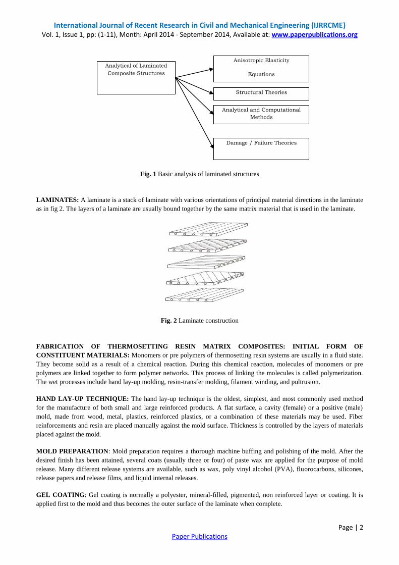
FIBER - REINFORCED COMPOSITE MATERIALS: Fiber-reinforced composite materials consist of high strength
and high modulus fibers in a matrix material. Reinforced steel bars embedded in concrete provide an example of fiber
reinforced composites. Analysis of structural elements made of laminated composite materials involves several steps. As
shown in fig 1, the analysis requires knowledge of anisotropic elasticity, structural theories (i.e., kinematics of
deformation) of laminates, analytical or computational methods to determine solutions of the governing equations, and
failure theories to predict modes of failures and to determine failure loads.
International Journal of Recent Research in Civil and Mechanical Engineering (IJRRCME) Vol. 1, Issue 1, pp: (1-11), Month: April 2014 - September 2014, Available at: www.paperpublications.org
Page | 2 Paper Publications
Fig. 1 Basic analysis of laminated structures
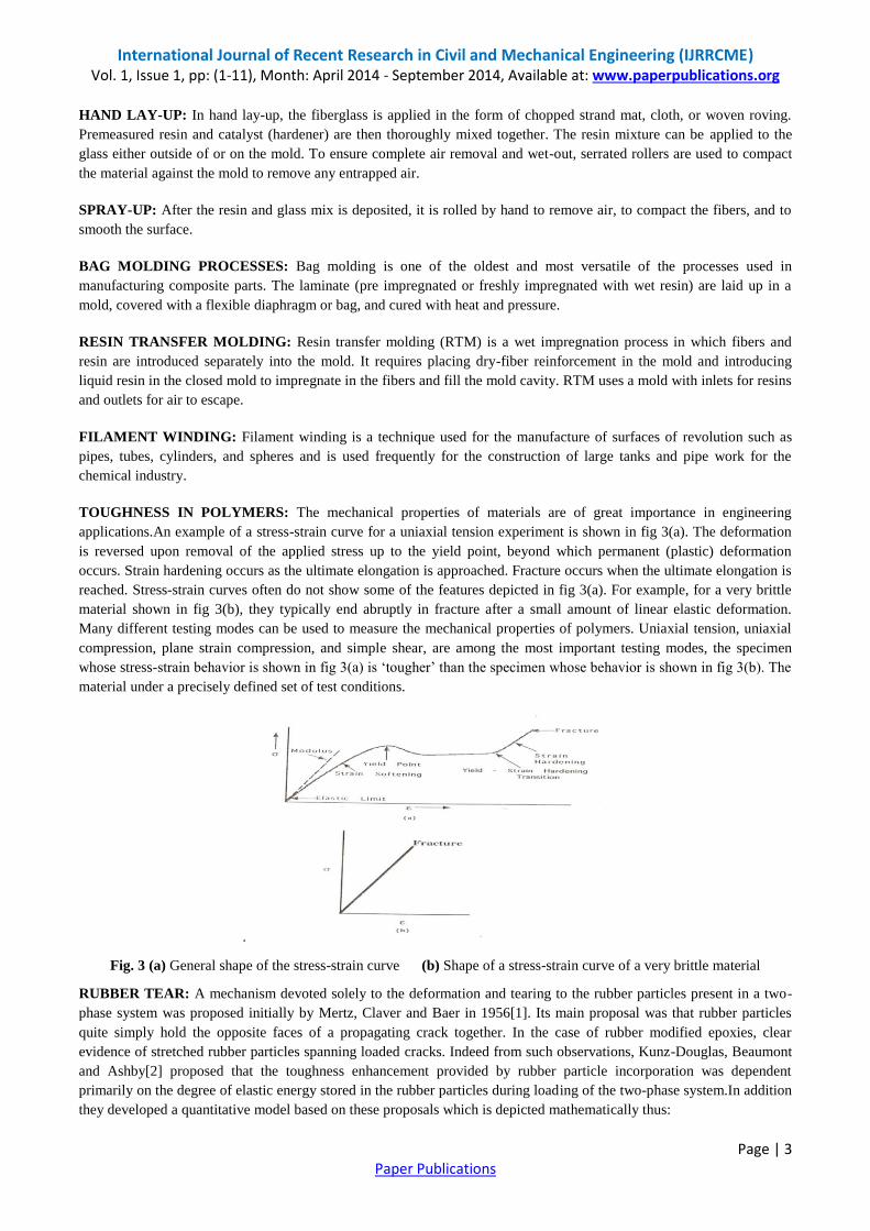
LAMINATES: A laminate is a stack of laminate with various orientations of principal material directions in the laminate
as in fig 2. The layers of a laminate are usually bound together by the same matrix material that is used in the laminate.
Fig. 2 Laminate construction
FABRICATION OF THERMOSETTING RESIN MATRIX COMPOSITES: INITIAL FORM OF
CONSTITUENT MATERIALS: Monomers or pre polymers of thermosetting resin systems are usually in a fluid state.
They become solid as a result of a chemical reaction. During this chemical reaction, molecules of monomers or pre
polymers are linked together to form polymer networks. This process of linking the molecules is called polymerization.
The wet processes include hand lay-up molding, resin-transfer molding, filament winding, and pultrusion.
HAND LAY-UP TECHNIQUE: The hand lay-up technique is the oldest, simplest, and most commonly used method
for the manufacture of both small and large reinforced products. A flat surface, a cavity (female) or a positive (male)
mold, made from wood, metal, plastics, reinforced plastics, or a combination of these materials may be used. Fiber
reinforcements and resin are placed manually against the mold surface. Thickness is controlled by the layers of materials
placed against the mold.
MOLD PREPARATION: Mold preparation requires a thorough machine buffing and polishing of the mold. After the
desired finish has been attained, several coats (usually three or four) of paste wax are applied for the purpose of mold
release. Many different release systems are available, such as wax, poly vinyl alcohol (PVA), fluorocarbons, silicones,
release papers and release films, and liquid internal releases.
GEL COATING: Gel coating is normally a polyester, mineral-filled, pigmented, non reinforced layer or coating. It is
applied first to the mold and thus becomes the outer surface of the laminate when complete.
Analytical of Laminated
Composite Structures
Anisotropic Elasticity
Equations
Structural Theories
Analytical and Computational
Methods
Damage / Failure Theories
International Journal of Recent Research in Civil and Mechanical Engineering (IJRRCME) Vol. 1, Issue 1, pp: (1-11), Month: April 2014 - September 2014, Available at: www.paperpublications.org
Page | 3 Paper Publications
HAND LAY-UP: In hand lay-up, the fiberglass is applied in the form of chopped strand mat, cloth, or woven roving.
Premeasured resin and catalyst (hardener) are then thoroughly mixed together. The resin mixture can be applied to the
glass either outside of or on the mold. To ensure complete air removal and wet-out, serrated rollers are used to compact
the material against the mold to remove any entrapped air.
SPRAY-UP: After the resin and glass mix is deposited, it is rolled by hand to remove air, to compact the fibers, and to
smooth the surface.
BAG MOLDING PROCESSES: Bag molding is one of the oldest and most versatile of the processes used in
manufacturing composite parts. The laminate (pre impregnated or freshly impregnated with wet resin) are laid up in a
mold, covered with a flexible diaphragm or bag, and cured with heat and pressure.
RESIN TRANSFER MOLDING: Resin transfer molding (RTM) is a wet impregnation process in which fibers and
resin are introduced separately into the mold. It requires placing dry-fiber reinforcement in the mold and introducing
liquid resin in the closed mold to impregnate in the fibers and fill the mold cavity. RTM uses a mold with inlets for resins
and outlets for air to escape.
FILAMENT WINDING: Filament winding is a technique used for the manufacture of surfaces of revolution such as
pipes, tubes, cylinders, and spheres and is used frequently for the construction of large tanks and pipe work for the
chemical industry.
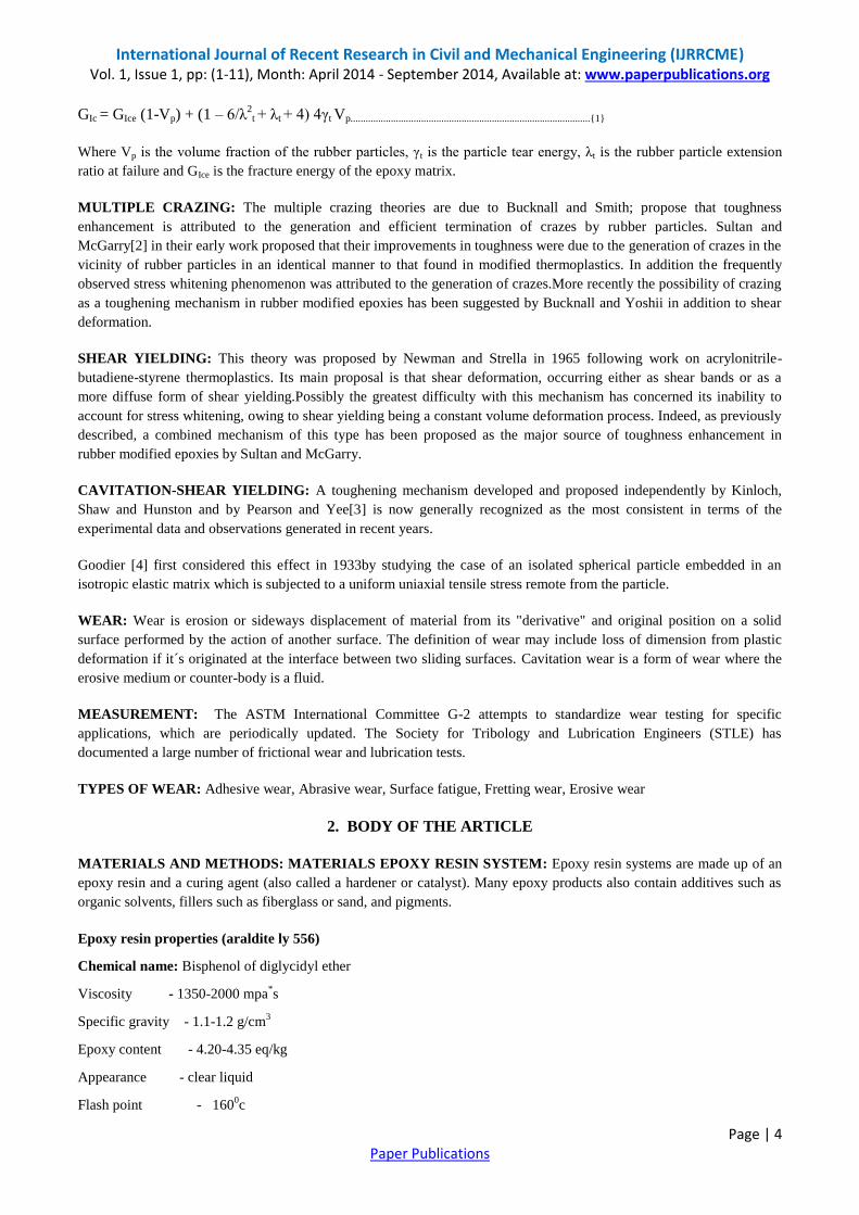
TOUGHNESS IN POLYMERS: The mechanical properties of materials are of great importance in engineering
applications.An example of a stress-strain curve for a uniaxial tension experiment is shown in fig 3(a). The deformation
is reversed upon removal of the applied stress up to the yield point, beyond which permanent (plastic) deformation
occurs. Strain hardening occurs as the ultimate elongation is approached. Fracture occurs when the ultimate elongation is
reached. Stress-strain curves often do not show some of the features depicted in fig 3(a). For example, for a very brittle
material shown in fig 3(b), they typically end abruptly in fracture after a small amount of linear elastic deformation.
Many different testing modes can be used to measure the mechanical properties of polymers. Uniaxial tension, uniaxial
compression, plane strain compression, and simple shear, are among the most important testing modes, the specimen
whose stress-strain behavior is shown in fig 3(a) is „tougher‟ than the specimen whose behavior is shown in fig 3(b). The
material under a precisely defined set of test conditions.
Fig. 3 (a) General shape of the stress-strain curve (b) Shape of a stress-strain curve of a very brittle material
RUBBER TEAR: A mechanism devoted solely to the deformation and tearing to the rubber particles present in a two-
phase system was proposed initially by Mertz, Claver and Baer in 1956[1]. Its main proposal was that rubber particles
quite simply hold the opposite faces of a propagating crack together. In the case of rubber modified epoxies, clear
evidence of stretched rubber particles spanning loaded cracks. Indeed from such observations, Kunz-Douglas, Beaumont
and Ashby[2] proposed that the toughness enhancement provided by rubber particle incorporation was dependent
primarily on the degree of elastic energy stored in the rubber particles during loading of the two-phase system.In addition
they developed a quantitative model based on these proposals which is depicted mathematically thus:
International Journal of Recent Research in Civil and Mechanical Engineering (IJRRCME) Vol. 1, Issue 1, pp: (1-11), Month: April 2014 - September 2014, Available at: www.paperpublications.org
Page | 4 Paper Publications
GIc = GIce (1-Vp) + (1 – 6/λ2t + λt + 4) 4γt Vp...............................................................................................{1}
Where Vp is the volume fraction of the rubber particles, γt is the particle tear energy, λt is the rubber particle extension
ratio at failure and GIce is the fracture energy of the epoxy matrix.
MULTIPLE CRAZING: The multiple crazing theories are due to Bucknall and Smith; propose that toughness
enhancement is attributed to the generation and efficient termination of crazes by rubber particles. Sultan and
McGarry[2] in their early work proposed that their improvements in toughness were due to the generation of crazes in the
vicinity of rubber particles in an identical manner to that found in modified thermoplastics. In addition the frequently
observed stress whitening phenomenon was attributed to the generation of crazes.More recently the possibility of crazing
as a toughening mechanism in rubber modified epoxies has been suggested by Bucknall and Yoshii in addition to shear
deformation.
SHEAR YIELDING: This theory was proposed by Newman and Strella in 1965 following work on acrylonitrile-
butadiene-styrene thermoplastics. Its main proposal is that shear deformation, occurring either as shear bands or as a
more diffuse form of shear yielding.Possibly the greatest difficulty with this mechanism has concerned its inability to
account for stress whitening, owing to shear yielding being a constant volume deformation process. Indeed, as previously
described, a combined mechanism of this type has been proposed as the major source of toughness enhancement in
rubber modified epoxies by Sultan and McGarry.
CAVITATION-SHEAR YIELDING: A toughening mechanism developed and proposed independently by Kinloch,
Shaw and Hunston and by Pearson and Yee[3] is now generally recognized as the most consistent in terms of the
experimental data and observations generated in recent years.
Goodier [4] first considered this effect in 1933by studying the case of an isolated spherical particle embedded in an
isotropic elastic matrix which is subjected to a uniform uniaxial tensile stress remote from the particle.
WEAR: Wear is erosion or sideways displacement of material from its "derivative" and original position on a solid
surface performed by the action of another surface. The definition of wear may include loss of dimension from plastic
deformation if it´s originated at the interface between two sliding surfaces. Cavitation wear is a form of wear where the
erosive medium or counter-body is a fluid.
MEASUREMENT: The ASTM International Committee G-2 attempts to standardize wear testing for specific
applications, which are periodically updated. The Society for Tribology and Lubrication Engineers (STLE) has
documented a large number of frictional wear and lubrication tests.
TYPES OF WEAR: Adhesive wear, Abrasive wear, Surface fatigue, Fretting wear, Erosive wear
2. BODY OF THE ARTICLE
MATERIALS AND METHODS: MATERIALS EPOXY RESIN SYSTEM: Epoxy resin systems are made up of an
epoxy resin and a curing agent (also called a hardener or catalyst). Many epoxy products also contain additives such as
organic solvents, fillers such as fiberglass or sand, and pigments.
Epoxy resin properties (araldite ly 556)
Chemical name: Bisphenol of diglycidyl ether
Viscosity - 1350-2000 mpa*s
Specific gravity - 1.1-1.2 g/cm3
Epoxy content
- 4.20-4.35 eq/kg
Appearance - clear liquid
Flash point - 1600c
International Journal of Recent Research in Civil and Mechanical Engineering (IJRRCME) Vol. 1, Issue 1, pp: (1-11), Month: April 2014 - September 2014, Available at: www.paperpublications.org
Page | 5 Paper Publications
Epoxy hardener properties (araldite hy 951)
Viscosity - 10-20 mpa*s
Specific gravity - 0.98 g/cm3
Appearance - clear liquid
Flash point - 1100c
GLASS FIBRE: Over 95% of the fibers used in reinforced plastics are glass fibers, as they are inexpensive, easy to
manufacture and possess high strength and stiffness with respect to the plastics with which they are reinforced. Addition
of chemicals to silica sand while making glass yields different types of glasses. E-Glass has been used extensively in
polymer matrix composites, commonly termed “fibreglass”.
FIBRE MANUFACTURE: Glass fibres are generally produced using melt spinning techniques. These involve melting
the glass composition into a platinum crown which has small holes for the molten glass to flow. Continuous fibres can be
drawn out through the holes and wound onto spindles, while short fibres may be produced by spinning the crown, which
forces molten glass out through the holes centrifugally. Fibres are cut to length using mechanical means or air jets. As
fibres are being produced, they are normally treated with sizing and coupling agents. These reduce the effects of fibre-
fibre abrasion which can significantly degrade the mechanical strength of the individual fibres. Other treatments may also
be used to promote wetting and adherence of the matrix material to the fibre.
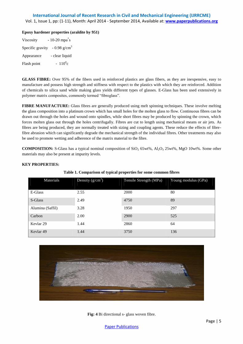
COMPOSITION: S-Glass has a typical nominal composition of SiO2 65wt%, Al2O3 25wt%, MgO 10wt%. Some other
materials may also be present at impurity levels.
KEY PROPERTIES:
Table 1. Comparison of typical properties for some common fibres
Materials Density (g/cm3) Tensile Strength (MPa) Young modulus (GPa)
E-Glass 2.55 2000 80
S-Glass 2.49 4750 89
Alumina (Saffil) 3.28 1950 297
Carbon 2.00 2900 525
Kevlar 29 1.44 2860 64
Kevlar 49 1.44 3750 136
Fig: 4 Bi directional s- glass woven fibre.
International Journal of Recent Research in Civil and Mechanical Engineering (IJRRCME) Vol. 1, Issue 1, pp: (1-11), Month: April 2014 - September 2014, Available at: www.paperpublications.org
Page | 6 Paper Publications
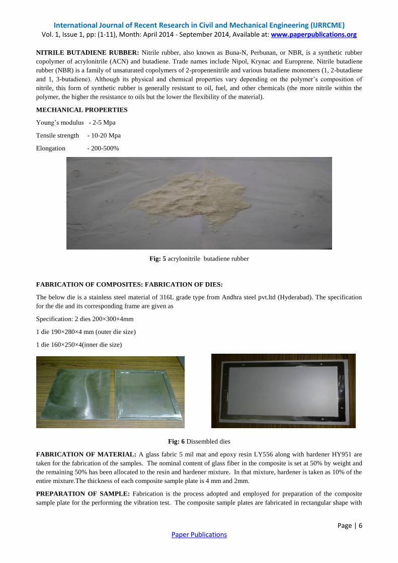
NITRILE BUTADIENE RUBBER: Nitrile rubber, also known as Buna-N, Perbunan, or NBR, is a synthetic rubber
copolymer of acrylonitrile (ACN) and butadiene. Trade names include Nipol, Krynac and Europrene. Nitrile butadiene
rubber (NBR) is a family of unsaturated copolymers of 2-propenenitrile and various butadiene monomers (1, 2-butadiene
and 1, 3-butadiene). Although its physical and chemical properties vary depending on the polymer‟s composition of
nitrile, this form of synthetic rubber is generally resistant to oil, fuel, and other chemicals (the more nitrile within the
polymer, the higher the resistance to oils but the lower the flexibility of the material).
MECHANICAL PROPERTIES
Young‟s modulus - 2-5 Mpa
Tensile strength - 10-20 Mpa
Elongation - 200-500%
Fig: 5 acrylonitrile butadiene rubber
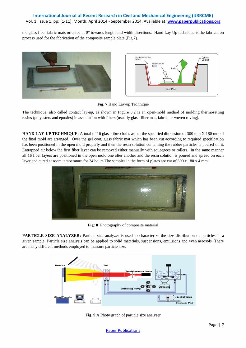
FABRICATION OF COMPOSITES: FABRICATION OF DIES:
The below die is a stainless steel material of 316L grade type from Andhra steel pvt.ltd (Hyderabad). The specification
for the die and its corresponding frame are given as
Specification: 2 dies 200×300×4mm
1 die 190×280×4 mm (outer die size)
1 die 160×250×4(inner die size)
Fig: 6 Dissembled dies
FABRICATION OF MATERIAL: A glass fabric 5 mil mat and epoxy resin LY556 along with hardener HY951 are
taken for the fabrication of the samples. The nominal content of glass fiber in the composite is set at 50% by weight and
the remaining 50% has been allocated to the resin and hardener mixture. In that mixture, hardener is taken as 10% of the
entire mixture.The thickness of each composite sample plate is 4 mm and 2mm.
PREPARATION OF SAMPLE: Fabrication is the process adopted and employed for preparation of the composite
sample plate for the performing the vibration test. The composite sample plates are fabricated in rectangular shape with
International Journal of Recent Research in Civil and Mechanical Engineering (IJRRCME) Vol. 1, Issue 1, pp: (1-11), Month: April 2014 - September 2014, Available at: www.paperpublications.org
Page | 7 Paper Publications
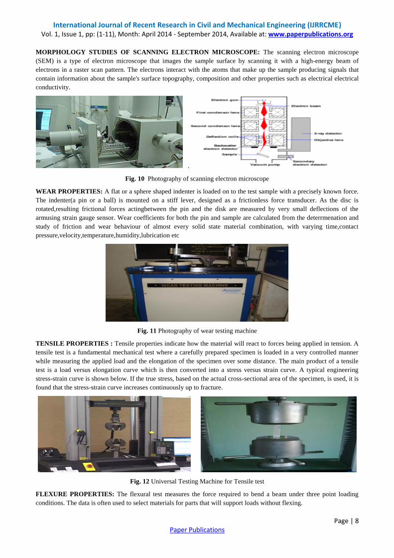
the glass fiber fabric mats oriented at 0° towards length and width directions. Hand Lay Up technique is the fabrication
process used for the fabrication of the composite sample plate (Fig.7).
Fig. 7 Hand Lay-up Technique
The technique, also called contact lay-up, as shown in Figure 3.2 is an open-mold method of molding thermosetting
resins (polyesters and epoxies) in association with fibers (usually glass-fiber mat, fabric, or woven roving).
HAND LAY-UP TECHNIQUE: A total of 16 glass fibre cloths as per the specified dimension of 300 mm X 180 mm of
the final mold are arranged. Over the gel coat, glass fabric mat which has been cut according to required specification
has been positioned in the open mold properly and then the resin solution containing the rubber particles is poured on it.
Entrapped air below the first fiber layer can be removed either manually with squeegees or rollers. In the same manner
all 16 fiber layers are positioned in the open mold one after another and the resin solution is poured and spread on each
layer and cured at room temperature for 24 hours.The samples in the form of plates are cut of 300 x 180 x 4 mm.
Fig: 8 Photography of composite material
PARTICLE SIZE ANALYZER: Particle size analyzer is used to characterize the size distribution of particles in a
given sample. Particle size analysis can be applied to solid materials, suspensions, emulsions and even aerosols. There
are many different methods employed to measure particle size.
Fig. 9 A Photo graph of particle size analyser
International Journal of Recent Research in Civil and Mechanical Engineering (IJRRCME) Vol. 1, Issue 1, pp: (1-11), Month: April 2014 - September 2014, Available at: www.paperpublications.org
Page | 8 Paper Publications
MORPHOLOGY STUDIES OF SCANNING ELECTRON MICROSCOPE: The scanning electron microscope
(SEM) is a type of electron microscope that images the sample surface by scanning it with a high-energy beam of
electrons in a raster scan pattern. The electrons interact with the atoms that make up the sample producing signals that
contain information about the sample's surface topography, composition and other properties such as electrical electrical
conductivity.
.
Fig. 10 Photography of scanning electron microscope
WEAR PROPERTIES: A flat or a sphere shaped indenter is loaded on to the test sample with a precisely known force.
The indenter(a pin or a ball) is mounted on a stiff lever, designed as a frictionless force transducer. As the disc is
rotated,resulting frictional forces actingbetween the pin and the disk are measured by very small deflections of the
armusing strain gauge sensor. Wear coefficients for both the pin and sample are calculated from the deterrmenation and
study of friction and wear behaviour of almost every solid state material combination, with varying time,contact
pressure,velocity,temperature,humidity,lubrication etc
Fig. 11 Photography of wear testing machine
TENSILE PROPERTIES : Tensile properties indicate how the material will react to forces being applied in tension. A
tensile test is a fundamental mechanical test where a carefully prepared specimen is loaded in a very controlled manner
while measuring the applied load and the elongation of the specimen over some distance. The main product of a tensile
test is a load versus elongation curve which is then converted into a stress versus strain curve. A typical engineering
stress-strain curve is shown below. If the true stress, based on the actual cross-sectional area of the specimen, is used, it is
found that the stress-strain curve increases continuously up to fracture.
Fig. 12 Universal Testing Machine for Tensile test
FLEXURE PROPERTIES: The flexural test measures the force required to bend a beam under three point loading
conditions. The data is often used to select materials for parts that will support loads without flexing.
International Journal of Recent Research in Civil and Mechanical Engineering (IJRRCME) Vol. 1, Issue 1, pp: (1-11), Month: April 2014 - September 2014, Available at: www.paperpublications.org
Page | 9 Paper Publications
Fig. 13 Universal Testing Machine for flexure test
EVALUATION OF WEIGHT FRACTIONS: Burn out test is carried out as per ASTM standards D618 to find the
weight fractions of fibers and matrix present in composites. Three specimens are tested using electric muffle furnace. The
specimens of size 20mm X 20mm are considered for the test. The average fiber weight fraction is found as 40 % of the
total weight of the each sample.
Fig. 14(a) Weight of the specimen (b) Specimen in muffle furnace.
III. RESULTS AND DISCUSSIONS
MORPHOLOGY STUDIES OF PARTICLE SIZE ANALYZER:
Fig: 15 Morphology studies of particle size analyzer measurement results
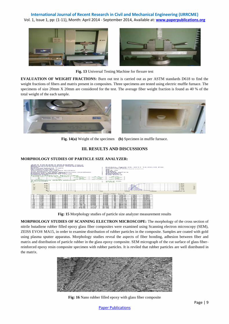
MORPHOLOGY STUDIES OF SCANNING ELECTRON MICROSCOPE: The morphology of the cross section of
nitrile butadiene rubber filled epoxy glass fiber composites were examined using Scanning electron microscopy (SEM),
ZEISS EVO® MA15, in order to examine distribution of rubber particles in the composite. Samples are coated with gold
using plasma sputter apparatus. Morphology studies reveal the aspects of fiber bonding, adhesion between fiber and
matrix and distribution of particle rubber in the glass epoxy composite. SEM micrograph of the cut surface of glass fiber-
reinforced epoxy resin composite specimen with rubber particles. It is reviled that rubber particles are well distributed in
the matrix.
Fig: 16 Nano rubber filled epoxy with glass fiber composite
International Journal of Recent Research in Civil and Mechanical Engineering (IJRRCME) Vol. 1, Issue 1, pp: (1-11), Month: April 2014 - September 2014, Available at: www.paperpublications.org
Page | 10 Paper Publications
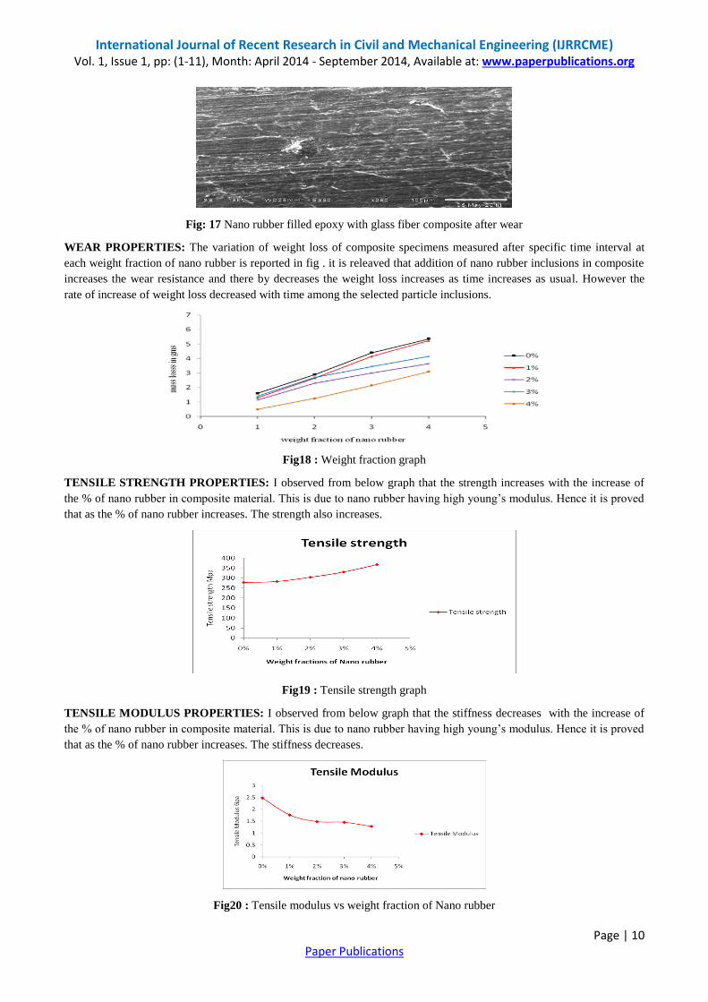
Fig: 17 Nano rubber filled epoxy with glass fiber composite after wear
WEAR PROPERTIES: The variation of weight loss of composite specimens measured after specific time interval at
each weight fraction of nano rubber is reported in fig . it is releaved that addition of nano rubber inclusions in composite
increases the wear resistance and there by decreases the weight loss increases as time increases as usual. However the
rate of increase of weight loss decreased with time among the selected particle inclusions.
Fig18 : Weight fraction graph
TENSILE STRENGTH PROPERTIES: I observed from below graph that the strength increases with the increase of
the % of nano rubber in composite material. This is due to nano rubber having high young‟s modulus. Hence it is proved
that as the % of nano rubber increases. The strength also increases.
Fig19 : Tensile strength graph
TENSILE MODULUS PROPERTIES: I observed from below graph that the stiffness decreases with the increase of
the % of nano rubber in composite material. This is due to nano rubber having high young‟s modulus. Hence it is proved
that as the % of nano rubber increases. The stiffness decreases.
Fig20 : Tensile modulus vs weight fraction of Nano rubber

International Journal of Recent Research in Civil and Mechanical Engineering (IJRRCME) Vol. 1, Issue 1, pp: (1-11), Month: April 2014 - September 2014, Available at: www.paperpublications.org
Page | 11 Paper Publications
FLEXURAL PROPERTIES: FLEXURAL STRENGTH PROPERTIES: I observed from below graph that the
strength increases with the increase of the % of nano rubber in composite material. This is due to nano rubber having
high young‟s modulus. Hence it is proved that as the % of nano rubber increases. The strength also increases.
Fig21: Flexural strength vs weight fractions of nano rubber
FLEXURAL MODULUS PROPERTIES: I observed from below graph that the stiffness decreases with the increase
of the % of nano rubber in composite material. This is due to nano rubber having high young‟s modulus. Hence it is
proved that as the % of nano rubber increases. The stiffness decreases.
Fig22: Flexural modulus vs weight fraction nano rubber
IV. CONCLUSION
The enhancement of abrasive wear properties of epoxy glass fiber composites are carried out through the addition of
nano nitrile butadiene rubber particles. Samples are fabricated with different weight fraction of nitrile butadiene rubber
using hand lay up technique.
The morphology studies of nano nitrile butadiene rubber dispersion in epoxy glass fiber composite studied using
scanning electron microscope.
The experimental studies on associate properties like strength, stiffness are in tension and flexural is also carried out.
The influence of weight fraction of nitrile butadiene rubber is on wear, tensile and flexural properties are carried
out.
Among the selected weight fractions 4% weight fraction is exhibited better wear, tensile and flexural properties are
observed.
REFERENCES
[1] Studies on heterogeneous polymeric systems by E. H. Merz, G. C. Claver, M. Baer.
[2] Rubber Toughened Engineering Plastics edited by A. A. Collyer.
[3] Advanced routes for polymer toughening byKinloch, Shaw and Hunston and by Pearson and Yee.
[4] J. N. Goodier, J. Appl. Mech., 1963, 1, 39.