effect of morphology and extent of infiltration on the cohesivity and dispersion mechanisms of...
TRANSCRIPT

Chemical Engineering Science 62 (2007) 3740–3747www.elsevier.com/locate/ces
Effect of morphology and extent of infiltration on the cohesivity anddispersion mechanisms of particle agglomerates
P. Gopalkrishnana,1, I. Manas-Zloczowera, D.L. Fekeb,∗aDepartment of Macromolecular Science and Engineering, USA
bDepartment of Chemical Engineering, Case Western Reserve University, Cleveland, OH 44106, USA
Received 2 January 2007; received in revised form 26 March 2007; accepted 27 March 2007Available online 6 April 2007
Abstract
A unified approach to predict the tendency for dispersion of particle agglomerates, inclusive of a wide range of particle and agglomerateproperties, is presented. This framework is applied to analyze the behavior of three prototypical materials (fumed silica, calcium carbonateand titanium dioxide) across a range of agglomerate packing densities. Simulations of dispersion phenomena, which employ our previouslydeveloped solution for liquid–bridge interactions for wet interparticle contacts and the Rumpf model for the tensile strength of the dry andwet portions of the agglomerate, have been performed. Various mechanisms of dispersion are predicted for various conditions of agglomeratedensity and extent of fluid infiltration. These range from an adhesive mechanism at the wet–dry interface for sparse materials to a cohesivemechanism by erosion as agglomerate density increases. The results correspond well with the results of earlier experimental studies involvingthe same materials.� 2007 Elsevier Ltd. All rights reserved.
Keywords: Agglomerate; DEM; Dispersion; Liquid bridges; Particle; Simulation
1. Introduction
Control of the dispersion process for particle agglomeratesis of prime importance in optimizing the properties of suspen-sions and composite materials. In the case of dry agglomeratesof fumed silica (Boyle et al., 2005; Scurati, 2002), calcium car-bonate (Levresse et al., 2002), titania (Lee et al., 1993) and car-bon black (Rwei et al., 1990), dispersion has been observed toproceed via a classical erosion mechanism wherein small frag-ments sequentially detach from the surface of the agglomerate.When processing conditions are such that little or no process-ing fluid is imbibed into the agglomerate during dispersion, thiserosion mechanism can be classified as a dry cohesive mech-anism of dispersion. In this case, the properties of the particleand the packing morphology within the agglomerate togetherdetermine the cohesive strength of the agglomerate and its re-sponse to applied hydrodynamic shear.
∗ Corresponding author. Tel.: +1 216 368 2750; fax: +1 216 368 3016.E-mail address: [email protected] (D.L. Feke).
1 Present address: Procter and Gamble Inc., Cincinnati, Ohio, USA.
0009-2509/$ - see front matter � 2007 Elsevier Ltd. All rights reserved.doi:10.1016/j.ces.2007.03.037
Fluid infiltration into such dry agglomerates has been ob-served to change the apparent cohesivity of the agglomerates.Depending on the particle characteristics and the extent of fluidinfiltration, a failure locus at the advancing liquid interface maybe created (Boyle et al., 2005). In such cases, the agglomeratedisperses by what is known as an adhesive mechanism in whichfragments containing wetted particles pull away from the dryinterior portions of the agglomerate. This dispersion mechanismis associated with agglomerates of loosely packed particles withopen morphologies such as fumed silica. In such systems, asfluid infiltrates, the capillary pressure exerted by the infiltrat-ing liquid causes rearrangement of the packing structure. Moredensely packed agglomerates resist infiltration-driven packingrearrangement to a greater extent, thereby reducing the ten-dency for dispersion by an adhesive mechanism and resortingto the traditional cohesive or erosion-based dispersion mecha-nism.
Prediction of dispersion mode, dispersion kinetics, and thenature of the fragments produced by dispersion would beof significant utility in the applications involving dispersion

P. Gopalkrishnan et al. / Chemical Engineering Science 62 (2007) 3740–3747 3741
processing. Based on the desired dispersion outcomes,customized processing conditions (e.g., flow geometry andintensity, presoaking conditions which determine the extent ofinfiltration, etc.) could then be established.
In this work, we describe a modeling approach that providesa first step towards determining the desired processing condi-tions to be imposed. Our approach employs a distinct elementmethod (DEM) (Cundall and Strack, 1979) in which materialparameters are inputted as variables in computing the forcesactive within the agglomerates. However, in contrast to a timeand resource-consuming model on the micro-scale of the in-dividual particles, we employ a meso-scale DEM approach toencompass bulk effects of the detachment of entire fragments(Gopalkrishnan et al., 2005). This enables each scenario tobe modeled on a moderately powered desktop within a user-friendly Matlab environment within a few minutes. The overallresponse of the agglomerates to dispersion conditions can thenbe predicted. We apply this framework to analyze the dispersionbehavior of three prototypical materials that have been studiedexperimentally (fumed silica, calcium carbonate and titaniumdioxide) across a range of agglomerate packing densities.
Prediction of dispersion mode, dispersion kinetics, and thenature of the fragments produced by dispersion are of signifi-cant utility in particle processing applications. Controlling thefinal dispersed particle size affects the mechanical, optical, andtransport properties of polymer composites as well as othermulti-phase systems.
2. Dispersion model
2.1. Interaction forces within agglomerates
The methodology for predicting agglomerate dispersion be-havior described in a previous study (Gopalkrishnan et al.,2005) is used here. The agglomerate is depicted in Fig. 1 as astring of seven potential fragments defined with respect to dif-ferent failure loci. Each fragment is presumed to have a mass inproportion to its volume, and to be interacting with its neighborfragments via relevant interparticle forces. Such an abstractionof the agglomerate on the scale of fragments as opposed to in-dividual particles, has been shown (Gopalkrishnan et al., 2005)to be adequate to allow depiction of the different dispersionmechanisms. Here we employ the same model to contrast mor-phology and fluid infiltration effects in materials of differentdensities and how these drive their different dispersion mecha-nisms. Excellent corroboration between model and experimentwas obtained with even secondary responses being reproducedin the modeling results.
In previous work (Gopalkrishnan et al., 2002) we have pre-sented an analytical solution for the fluid-induced interactionsdue to a pendular liquid bridge between particles. In dimen-sionless form, the force expression for the total interaction isestimated by
FLB
�R�≡ F ∗
LB = R∗2
R∗1(R∗
1 + R∗2) + 3
2CaLB
R∗42
(R∗22 + h∗)2 , (1)
3
7
1
FN_1
FN_1
d
Dry coreL1
L2
L3
2
4
6
5
FN_3
FN_2
FN_3
FN_2
Fig. 1. Seven spheres represent the potential fragments of the agglomerate.These are chosen such that massfragment =masssphere. L1, L2, and L3 are therelative separation distances between fragments which are compared to hrupfrom Eq. (3) to indicate failure at any contact. d is the depth of infiltration(shown is 30% of agglomerate radius). L1 > hrup indicates wet cohesivefailure; L2 > hrup indicates adhesive failure; L3 > hrup indicates dry cohesivefailure.
wherein F ∗LB is the total dimensionless liquid bridge force,
R the radius of particles bound by liquid bridge, � the liq-uid surface tension, R∗
1 the dimensionless primary radius ofcurvature = R1/R, R∗
2 the dimensionless secondary radius ofcurvature = R2/R, CaLB the dimensionless Capillary Numberdefined for liquid bridge geometries (Kroger and Rath, 1995),as
CaLB = �vR
�h= �v
�
(1
h∗
). (2)
Here, � is the viscosity of the liquid within the bridge, v isthe relative speed between two interacting particles located adistance h apart and attached by the liquid bridge, h∗ the di-mensionless separation scaled on R, the radius of the spheres.
Eq. (1) effectively collapses the capillary forces due to sur-face tension of the fluid and the viscous forces that dependon the dynamics of the interaction between constituent parti-cles into the Capillary Number CaLB . For a given system ofparticle–liquid interactions, i.e., constant viscosity and interfa-cial tension, the Capillary Number and radii of curvature onlydepend on the instantaneous liquid bridge extension achieved.Thus, by keeping the dynamics of interaction and fluid prop-erties constant, the dimensionless liquid bridge force scalesonly with the instantaneous dimensionless separation, h∗ takenfrom experiments on a reference system as described earlier(Gopalkrishnan et al., 2002).
Eq. (1) can quantify the dynamic response of an agglom-erate being distorted under shearing conditions on the scale

3742 P. Gopalkrishnan et al. / Chemical Engineering Science 62 (2007) 3740–3747
Table 1Primary and secondary units constituting the infiltrated agglomerate
Material Primary particlediameter Dprim (nm)
Apparent infiltration-induceddiameter Dapp (nm)
Fumed silica 8 700Calcium carbonate 80 300Titanium dioxide 167 ∼1000
of the units, i.e., individual pairs of particles. To extend thismodel to an overall partially infiltrated agglomerate, we em-ployed the form developed by Rumpf for the estimation of thetensile strength of infiltrated powders (Pietsch, 1991; Pierratand Caram, 1997). Thus, the tensile strength of the infiltratedouter portions of the agglomerate is determined from
�Wet_Tensile = �
1 − �
FLB
D2app
, (3)
where � is the volume fraction of solids within the agglomer-ate, and Dapp is the average diameter of the particles interactingthrough liquid bridges. This value differs from the actual sizeof primary particles (Dprim) due to clustering of primary par-ticles that occurs during fluid infiltration. This tensile strengthacting over the infiltrated shell portion of the agglomerate, es-timates the cohesive strength of the agglomerate sections ateach potential failure plane due to binder contributions (FLB),summed over the infiltrated cross-sectional area as �FLB (ap-plied in Eq. (6)).
Information on Dapp can be obtained from Washburn-typeexperiments designed to measure the capillary-pressure drivenfluid infiltration into beds of particles as a function of time. Suchstudies have been conducted at different overall bed-packingdensities (Scurati, 2002). Dapp was found to be greater thanDprim in all cases, although the disparity differed for each ma-terial investigated. The primary and the apparent particle sizesmeasured by the Washburn experiments for fumed silica andcalcium carbonate (Scurati, 2002) and titanium dioxide (Lee,1993) are tabulated in Table 1.
The cohesivity of the dry core, �Tensile (Rumpf, 1962) isgiven by
�Tensile = 1.1�
(1 − �)
A
24h2minDprim
, (4)
where A is the Hamaker constant, hmin = 2 nm is set as theminimum separation distance between particles of size Dprimcomprising the dry core, and � is the volume fraction of solidswithin the agglomerate. The cohesive force due to van der Waalsinteractions is summed from an estimate of the dry contactarea over each potential failure plane. The total cohesive forceresisting dispersion, at each plane is then the sum of the effectsof �Tensile and �Wet_Tensile acting on their respective dry andwet contact surfaces.
2.2. Imposition of rearrangement due to fluid infiltration inmodel
Previously (Gopalkrishnan et al., 2005), we have studied theeffect of predetermined structure rearrangement due to fluid in-filtration on the dispersion mechanism that is manifested. Wheninfiltration does not lead to rearrangement, the agglomeratestend to disperse via a cohesive failure mode. Here we calcu-late the extent of infiltration-induced rearrangement based onthe force balances prior to application of hydrodynamic forcein inducing rearrangement within the agglomerate. The samecomponents of the cohesive force, i.e., liquid bridge and drycontact interactions, act within the agglomerate, differently atdifferent loci depending on the relative distribution of liquidbridge and dry contacts. This results in varying rearrangementin different portions of the agglomerate at the time of startinghydrodynamic force application.
2.3. Dispersion criterion
The criterion for agglomerate breakage is based on Lian’sliquid–bridge rupture distance criterion between two spheres(Lian et al., 1993):
hrup = (1 + 0.5�)3√
VLB , (5)
where � is the contact angle and VLB is the volume of liq-uid within each liquid bridge. hrup has been shown to varyinsignificantly over a wide range of inter-particle separations.Here the liquid bridge interacts between two particles of meandiameter, Dapp due to infiltration-induced capillary pressureeffects. This is an appropriate criterion since at distances pre-dicted by Eq. (5), van der Waals forces between particles arenegligibly small, i.e., only liquid bridge forces persist to theseseparations.
2.4. Simulation approach
The modeling approach involves solving a coupled set offorce balances (Newton’s second law of motion) for the evolu-tion of each fragment position with time:
mdv
dt= FN + �FLB + �Fvdw, (6)
where m and v are the mass and instantaneous velocity of eachfragment, FN is the applied hydrodynamic force, �FLB is thetotal interaction force due to liquid bridges present at eachinter-segment plane, and �Fvdw is the total van der Waals forceacting at each plane.
The hydrodynamic force is derived from analytical expres-sion of the stress that acts on portions of impermeable spheressubjected to shear flows of prescribed strength and flow geom-etry. Since agglomerates can be up to two orders of magnitudeweaker in tension than in shear (Boyle, 2003), we study onlythe influence of the normal stress component in dispersing theagglomerate. In addition, we focus on simple-shear flow, andthus presume that the fracture surfaces are arranged perpen-dicular to the principal straining axis of the flow field, as in
P. Gopalkrishnan et al. / Chemical Engineering Science 62 (2007) 3740–3747 3743
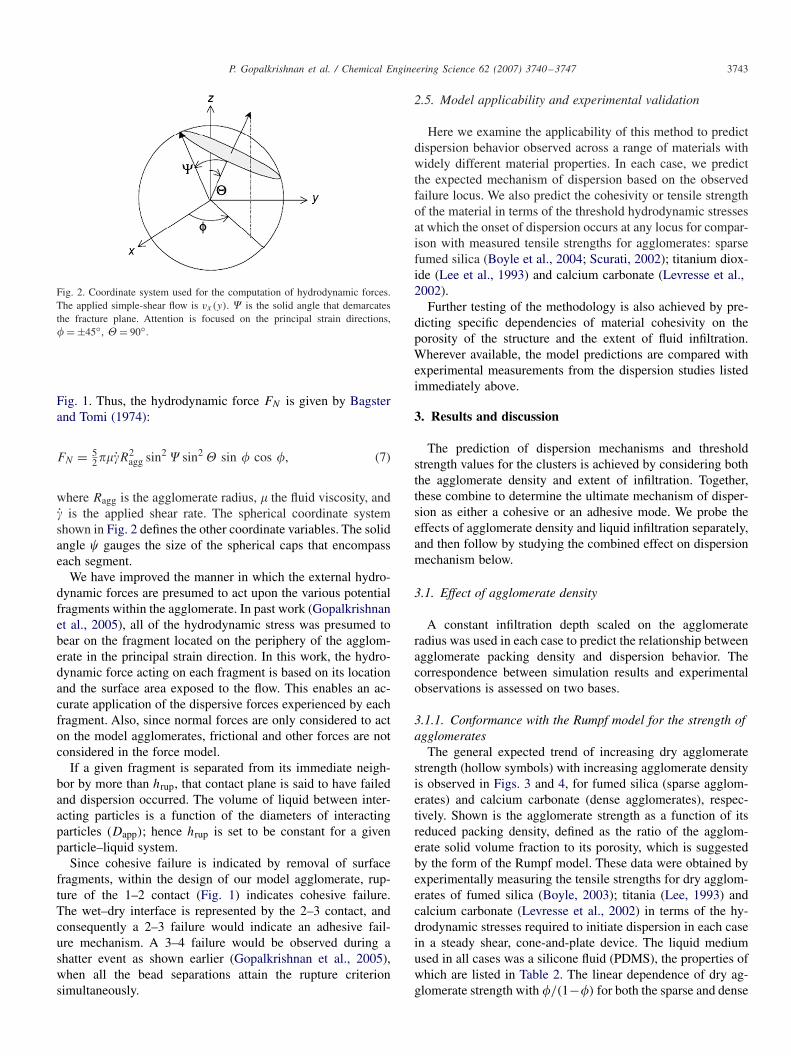
Fig. 2. Coordinate system used for the computation of hydrodynamic forces.The applied simple-shear flow is vx(y). � is the solid angle that demarcatesthe fracture plane. Attention is focused on the principal strain directions,� = ±45◦, = 90◦.
Fig. 1. Thus, the hydrodynamic force FN is given by Bagsterand Tomi (1974):
FN = 52��R2
agg sin2 � sin2 sin � cos �, (7)
where Ragg is the agglomerate radius, � the fluid viscosity, and is the applied shear rate. The spherical coordinate systemshown in Fig. 2 defines the other coordinate variables. The solidangle � gauges the size of the spherical caps that encompasseach segment.
We have improved the manner in which the external hydro-dynamic forces are presumed to act upon the various potentialfragments within the agglomerate. In past work (Gopalkrishnanet al., 2005), all of the hydrodynamic stress was presumed tobear on the fragment located on the periphery of the agglom-erate in the principal strain direction. In this work, the hydro-dynamic force acting on each fragment is based on its locationand the surface area exposed to the flow. This enables an ac-curate application of the dispersive forces experienced by eachfragment. Also, since normal forces are only considered to acton the model agglomerates, frictional and other forces are notconsidered in the force model.
If a given fragment is separated from its immediate neigh-bor by more than hrup, that contact plane is said to have failedand dispersion occurred. The volume of liquid between inter-acting particles is a function of the diameters of interactingparticles (Dapp); hence hrup is set to be constant for a givenparticle–liquid system.
Since cohesive failure is indicated by removal of surfacefragments, within the design of our model agglomerate, rup-ture of the 1–2 contact (Fig. 1) indicates cohesive failure.The wet–dry interface is represented by the 2–3 contact, andconsequently a 2–3 failure would indicate an adhesive fail-ure mechanism. A 3–4 failure would be observed during ashatter event as shown earlier (Gopalkrishnan et al., 2005),when all the bead separations attain the rupture criterionsimultaneously.
2.5. Model applicability and experimental validation
Here we examine the applicability of this method to predictdispersion behavior observed across a range of materials withwidely different material properties. In each case, we predictthe expected mechanism of dispersion based on the observedfailure locus. We also predict the cohesivity or tensile strengthof the material in terms of the threshold hydrodynamic stressesat which the onset of dispersion occurs at any locus for compar-ison with measured tensile strengths for agglomerates: sparsefumed silica (Boyle et al., 2004; Scurati, 2002); titanium diox-ide (Lee et al., 1993) and calcium carbonate (Levresse et al.,2002).
Further testing of the methodology is also achieved by pre-dicting specific dependencies of material cohesivity on theporosity of the structure and the extent of fluid infiltration.Wherever available, the model predictions are compared withexperimental measurements from the dispersion studies listedimmediately above.
3. Results and discussion
The prediction of dispersion mechanisms and thresholdstrength values for the clusters is achieved by considering boththe agglomerate density and extent of infiltration. Together,these combine to determine the ultimate mechanism of disper-sion as either a cohesive or an adhesive mode. We probe theeffects of agglomerate density and liquid infiltration separately,and then follow by studying the combined effect on dispersionmechanism below.
3.1. Effect of agglomerate density
A constant infiltration depth scaled on the agglomerateradius was used in each case to predict the relationship betweenagglomerate packing density and dispersion behavior. Thecorrespondence between simulation results and experimentalobservations is assessed on two bases.
3.1.1. Conformance with the Rumpf model for the strength ofagglomerates
The general expected trend of increasing dry agglomeratestrength (hollow symbols) with increasing agglomerate densityis observed in Figs. 3 and 4, for fumed silica (sparse agglom-erates) and calcium carbonate (dense agglomerates), respec-tively. Shown is the agglomerate strength as a function of itsreduced packing density, defined as the ratio of the agglom-erate solid volume fraction to its porosity, which is suggestedby the form of the Rumpf model. These data were obtained byexperimentally measuring the tensile strengths for dry agglom-erates of fumed silica (Boyle, 2003); titania (Lee, 1993) andcalcium carbonate (Levresse et al., 2002) in terms of the hy-drodynamic stresses required to initiate dispersion in each casein a steady shear, cone-and-plate device. The liquid mediumused in all cases was a silicone fluid (PDMS), the properties ofwhich are listed in Table 2. The linear dependence of dry ag-glomerate strength with �/(1−�) for both the sparse and dense

3744 P. Gopalkrishnan et al. / Chemical Engineering Science 62 (2007) 3740–3747
0
2000
4000
6000
8000
10000
12000
0 0.1 0.2 0.3 0.4 0.5
Tensile
str
ength
, P
a
Fumed Silica - DryFumed Silica - Infiltrated
φ / (1−φ)
Fig. 3. Agglomerate tensile strength as a function of the reduced agglomeratedensity for fumed silica. Dry tensile strength data from Boyle (2003). Forthe infiltrated case, the depth of infiltration (d) is 30% of the agglomerateradius. Infiltrating fluid is 60 Pa s PDMS.
0
2000
4000
6000
8000
10000
12000
14000
16000
18000
20000
0 0.1 0.2 0.3 0.4 0.5 0.6 0.7
Tensile
str
ength
, P
a
Calcium carbonate - dry
Calcium carbonate - infiltrated
φ / (1−φ)
Fig. 4. Agglomerate tensile strength as a function of the reduced volumefraction for calcium carbonate agglomerates. Dry tensile strength data fromLevresse et al. (2002). For the infiltrated case, the depth of infiltration (d)=5%of the agglomerate radius. Infiltrating fluid is 60 Pa s PDMS.
Table 2Physical properties of silicone fluid used in dispersion experiments
Fluid Viscosity (Pa s) Density × 10−3 (kg/m3) Surface tension (mJ/m2)
PDMS 60 0.97 21.3
agglomerates is in line with predictions of the Rumpf model(Rumpf,1962).
Also superposed in Figs. 3 and 4 are the predictions for tensilestrength of partially infiltrated agglomerates (solid symbols) offumed silica and calcium carbonate, respectively, as a functionof reduced agglomerate density. The earlier dispersion studiesfor fumed silica (Boyle et al., 2004) and calcium carbonate(Levresse et al., 2002) show clearly the effect of structuralrearrangement caused by the fluid infiltration process as well asthe reinforcing effects of the formed liquid bridges. This affectsthe strength of the infiltrated agglomerates and their kineticsof dispersion. However, infiltration affects different materialsdifferently as explained below, and we employ the model toprobe these effects:
Fumed silica: Sparse density regime. Fumed silica exhibitsa significant weakening on infiltration, at equivalent agglomer-
0.0002
0.0001
0
0.3 0.4 0.5 0.6 0.7 0.8 0.9 1 1.1
TI - A
PDMS : 10.000 cS
Shear Rate : 37.5 s-1
Ero
sio
n R
ate
Consta
nt, k
φ / (1−φ)
Fig. 5. Taken from Lee (1993). Erosion rate as a function of reduced compactdensity, �/(1 − �) for TiO2 agglomerates. When �/(1 − �) is near 0.4, theerosion rate is large due to weakened cohesivity of the agglomerates.
ate densities for dry and infiltrated agglomerates (Boyle et al.,2005). As seen from Fig. 3, at typical porosity values for fumedsilica (e.g. 90%, i.e., reduced density ∼ 0.11), the estimatedtensile strength for the model 30% infiltrated agglomerate ap-proximately equals the strength of the dry agglomerate. How-ever, as we move up the density axis, the infiltration-inducedweakening effect manifests itself, i.e., the infiltrated clusters(solid symbols) modeled with a constant infiltration depth of30% show lower tensile strength as compared to their dry coun-terparts as observed (Boyle et al., 2005).
Calcium carbonate: Dense regime. Levresse et al. (2002)demonstrated for calcium carbonate, a strengthening ofagglomerates on infiltration, inferred from the slower kinetics ofdispersion following liquid infiltration. In line with these exper-iments for calcium carbonate, the model predicts a significantenhancement of the strength of the agglomerates as a resultof infiltration. As the density of these agglomerates increases,their strength increases linearly, for both dry and infiltratedscenarios.
3.1.2. Effect of internal agglomerate morphology ondispersion kinetics
Specific insight on the dependence of dispersion behavioron agglomerate structure can be obtained from experiments ontitanium dioxide agglomerates. Measurements of erosion ratesof the dry TiO2 agglomerates as a function of the agglomeratedensity (Lee et al., 1993) have shown a rapid transition from fastkinetics to a slow regime with increasing agglomerate density(Fig. 5). This sharp transition was found to occur near a reducedagglomerate density of 0.4. It is expected that this variationin the nature of the behavior of agglomerates should manifestitself in our modeling efforts.
Infiltrated titanium dioxide agglomerates of increasingporosities were simulated for dispersion behavior. The level ofinfiltration in all these calculations was maintained constantat 5%. By monitoring the estimated dispersion times, a clearpicture of the effect of agglomerate density on the dispersionkinetics emerges. Fig. 6 plots a characteristic rate of disper-sion, defined here conveniently as the inverse of the time to

P. Gopalkrishnan et al. / Chemical Engineering Science 62 (2007) 3740–3747 3745
118
116
114
112
110
108
106
104
120
0.3 0.35 0.4 0.45 0.5
Dis
pers
ion r
ate
, (s
ec)-1
Titanium dioxide
φ / (1−φ)
Fig. 6. Transition in agglomerate dispersion rates with increasing agglom-erate density. Note the transition in dispersion kinetics between a reducedagglomerate predicted to occur at a density of 0.38–0.42.
φ / (1−φ)
0
1000
2000
3000
4000
5000
6000
7000
8000
9000
0.3 0.35 0.4 0.45 0.5
Tensile
str
ength
, P
a
Titanium dioxide - dry
Titanium dioxide - infiltrated
Fig. 7. Agglomerate tensile strength as a function of the reduced agglomeratedensity for titanium dioxide agglomerates. Depth of infiltration (d)= 30% ofthe agglomerate radius. Infiltrating fluid is 60 Pa s PDMS. Dry tensile strengthdata from Lee (1993 (2)).
agglomerate breakage, calculated in each case. As seen, thedispersion rate remains flat everywhere except in the region ofagglomerate density of approximately 0.4, where a transitionto a lower dispersion rate occurs. This can be attributed to astrengthening of the agglomerate beyond a critical value ofagglomerate density 0.4, leading to larger rupture times.
Fig. 7 plots the tensile strength of the dry (experimental val-ues) and infiltrated titanium dioxide agglomerates (predictedfrom the model) against agglomerate density. As expected, anincrease in agglomerate strength with density is observed. How-ever, while the tensile strength estimations for the infiltratedagglomerates reflect the effect of the transition in dispersiondynamics, the dry agglomerates do not. This can be attributedto the increased deformability of the agglomerate when infil-trated, as a result of which the response better traces the changein dispersion dynamics.
In Fig. 7, an inflection in the tensile strength separates a lin-ear dense regime from a linear low-density regime. At bothends of the agglomerate density spectrum, the dependence ofagglomerate strength on the reduced density is linear, in con-formance with the Rumpf model (Rumpf, 1962). The abruptshift in the prediction at a reduced density of ∼ 0.4 is indica-tive of a transition occurring within the agglomerate betweenthe dense and sparse morphologies.
0
200
400
600
800
1000
1200
0 5 10 15 20 25 30 35
Tensile
str
ength
, P
a
Fumed silica
% infiltration (d/Ragg
)
Fig. 8. Predicted agglomerate tensile strength as a function of the extentof infiltration for sparse fumed silica of typical porosity 0.9. The symbolsrepresent specific cases simulated, while the connecting line presents theexpected trends.
3.2. Effect of infiltration depth at constant porosity
A comprehensive experimental study of varying infiltrationdepth on agglomerate tensile strength has yet to be completed.However, this model allows us to probe this effect easily andprovides good agreement with preliminary quantitative obser-vations by Boyle et al. (2005) and Lee (1993) for fumed silicaand titanium dioxide, respectively.
The effect of the extent of infiltration on dispersion of par-tially infiltrated agglomerates can also be investigated by dis-persing agglomerates of the same porosity with varying degreesof infiltration. In agreement with experimental observations byBoyle (2003), model predictions for sparse fumed silica (poros-ity of 0.9) exhibit increased tensile strengths as the depth ofinfiltration of PDMS into the agglomerate increases, as seenfrom Fig. 8.
In contrast, for the case of titanium dioxide at a typical poros-ity of 0.69 (reduced agglomerate density of 0.45), an inflectionpoint in tensile strength is predicted at an infiltration depth of15–20% as seen in Fig. 9. This reflects the increased effect offluid-induced rearrangement on the inner fragments with in-creasing levels of infiltration.
3.3. Predicting dispersion mechanisms: effect of agglomeratedensity and extent of infiltration
The effects of solid packing density and the degree of fluidinfiltration-induced structure modification combine to deter-mine the final mechanism of dispersion of the agglomerates.
Fumed silica: For the case of fumed silica, an estimate ofthe capillary pressure driving fluid infiltration compared to theshear strength of fumed silica compacts shows it to be moresusceptible to rearrangement (Boyle et al., 2005) at the wet–dryinterface than calcium carbonate or titanium dioxide. Conse-quently, infiltrated silica agglomerates are known from experi-ment to fail by the adhesive mechanism at the advancing liquidinterface (Boyle et al., 2005). This is confirmed by our model,

3746 P. Gopalkrishnan et al. / Chemical Engineering Science 62 (2007) 3740–3747
0
1000
2000
3000
4000
5000
6000
7000
8000
9000
0 5 10 15 20 25 30 35
Tensile
str
ength
, P
a
Titanium dioxide
% infiltration (d/Ragg
)
Fig. 9. Predicted agglomerate tensile strength as a function of the extent ofinfiltration for titanium dioxide of typical porosity 0.69. Greater depths ofinfiltration induce larger fragments to be generated during dispersion (Leeet al., 1993) requiring larger applied hydrodynamic stresses (Levresse et al.,2001). The symbols represent the specific cases simulated.
0.00
0.10
0.20
0.30
0.40
0.50
0.60
0.70
0.80
0.90
1.00
0 0.01 0.02 0.03 0.04 0.05 0.06 0.07 0.08
Dimensionless time of shear
Dim
en
sio
nle
ss s
ep
ara
tio
n
Inter-fragment separation 1-2
Inter-fragment separation 2-3
Inter-fragment separation 3-4
Critical rupture distance
Fig. 10. Prediction of the dispersion of fumed silica agglomerates of porosity0.9, depicting the adhesive mechanism of dispersion at 30% infiltration.Applied hydrodynamic stress: 1140 Pa. Separation is made dimensionless onthe bridge rupture distance, hrup (Lian et al., 1993). Dimensionless time ofshear is related to the product of time and shear rate.
as seen from a plot of the relative separation distances betweenfragments as function of dimensionless time in Fig. 10. At 30%depth of infiltration, a hydrodynamic stress of 1140 Pa is re-quired to initiate dispersion.
However, as seen earlier, increasing levels of infiltration mayhinder dispersion. This is seen from the increase in the tensilestrength of fumed silica agglomerates with increasing infiltra-tion extents (Fig. 8).
We now proceed to contrast the dispersion behavior of theother materials investigated in the light of the above discussionon fumed silica.
Calcium carbonate: The behavior in the case of calciumcarbonate is markedly different on account of the increaseddensity of the material, in that fluid infiltration does not signif-icantly alter the agglomerate structure via rearrangement, andhence the mechanism by which dispersion proceeds. Moreover,as noted earlier (Levresse et al., 2002), experiments show a sig-
0.00
0.10
0.20
0.30
0.40
0.50
0.60
0.70
0.80
0.90
1.00
0 0.02 0.04 0.06 0.08 0.1 0.12 0.14
Dimensionless time of shear
Dim
ensio
nle
ss s
epara
tion Inter-fragment separation 1-2
Inter-fragment separation 2-3
Inter-fragment separation 3-4
Critical rupture criterion
Fig. 11. Prediction of the dispersion of calcium carbonate agglomerates ofporosity 0.7, depicting the cohesive mechanism of dispersion at 5% infiltration.Applied hydrodynamic stress: 10 140 Pa.
nificant increase in cohesivity for calcium carbonate agglom-erates on infiltration. At the infiltration depths that correspondto the size of each bead that constitutes the seven-fragmentmodel we employ in our DEM calculations, i.e., ∼ 30%infiltration, we observe that the agglomerate structure is sosignificantly strengthened that dispersion is not observed undertypically employed shearing conditions. However, using a lowerdepth of infiltration of 5%, we can corroborate the occurrenceof a cohesive mechanism of dispersion. Fig. 11 tracks the non-dimensionalized inter-fragment separations vis-à-vis the Lianet al. (1993) liquid bridge rupture criterion as a function ofthe dimensionless time of application of shear, for infiltratedcalcium carbonate agglomerates of porosity 0.7 at 5% depthof infiltration. The applied stress level at which dispersioninitiates is very high, at 10 140 Pa. This indicates a very signif-icant contribution of liquid bridges in altering the cohesivityof calcium carbonate agglomerates.
Titanium dioxide: Titanium dioxide agglomerates also exhibitdense-packed structures. Experiments conducted to monitorthe dispersion of TiO2 agglomerates by Lee et al. (1993), led tothe observation of the detachment of large fragments from theagglomerate on shearing after infiltration has occurred. Thesedetached fragments were comparable in size to the thicknessof the infiltrated portion, seemingly suggesting a wet–dry in-terfacial failure mechanism. By allowing for infiltration of thePDMS fluid, we are able to corroborate qualititatively, thedispersion behavior identified by Lee et al. (1993) throughidentification of failure loci corresponding to the size of theinfiltrated region. This indicates dispersion by an adhesivemechanism due to failure at the wet–dry interface. Fig. 12 mapsthe inter-fragment separations as a function of dimensionlessshear time for a titanium dioxide agglomerate of porosity 0.69(reduced agglomerate density ∼ 0.45), 30% infiltrated with60 Pa s PDMS fluid that fails when subjected to a hydrody-namic stress of 6300 Pa. In the range of agglomerate densitiesfor which we had dry agglomerate tensile strength data, thetensile strengths for the infiltrated agglomerates at correspond-ing densities, exhibit an increase due to the presence of liquidbridges (Fig. 7).

P. Gopalkrishnan et al. / Chemical Engineering Science 62 (2007) 3740–3747 3747
0.00
0.10
0.20
0.30
0.40
0.50
0.60
0.70
0.80
0.90
1.00
0 0.2 0.4 0.6 0.8 1
Dimensionless time of shear
Dim
ensio
nle
ss s
epara
tion Inter-fragment separation 1-2
Inter-fragment separation 2-3
Inter-fragment separation 3-4
Critical rupture criterion
Fig. 12. Prediction of the dispersion of titanium dioxide agglomerates ofporosity 0.69, depicting the adhesive mechanism of dispersion at 30% infil-tration. Applied hydrodynamic stress: 7680 Pa.
Titanium dioxide thus provides a transition case wherein in-filtration is seen to increase agglomerate cohesivity in line withthe behavioral trends observed for dense agglomerates althoughit also exhibits dispersion loci varying with the degree of infil-tration.
4. Conclusions
A single framework to investigate different dispersion phe-nomena and characterize the mechanism and efficacy of mix-ing has been developed. Since this model only requires easilyaccessible material parameters as input to compute the hydro-dynamics to be employed and predict corresponding dispersionbehavior, it finds potential application in the optimization ofdispersion processing. The applicability of this methodologyacross different materials has been tested and meaningful inter-pretations and predictions of experimentally observed phenom-ena have been made. Greater resolution on dispersion behaviorcan be easily achieved by increasing the number of potentialfailure loci that are incorporated into the modeling algorithm.
This modeling approach successfully distinguish betweenthe three dispersion modes; cohesive failure (failure in the drycore), adhesive failure (failure at the wet–dry interface) andinstantaneous shatter (simultaneous failure at all loci). Evenanomalies in behavior (e.g. variations in dispersion kinetics asa function of packing density) are reproduced by consideringthe influence of packing density, van der Waals interactions inthe dry phase and liquid bridges in the wetted portions of realagglomerates. This modeling approach provides a tool usefultowards designing particle-size distributions in multi-phasesystems. Based on the desired dispersion outcomes, customizedprocessing conditions (e.g., flow geometry and intensity,
presoaking conditions which determine the extent of infiltra-tion, etc.) could then be established.
Acknowledgments
The authors gratefully acknowledge the financial support ofGrant # 35561-AC9 of the Petroleum Research Fund of theAmerican Chemical Society.
References
Bagster, D.F., Tomi, D., 1974. The stresses within a sphere in simple flowfields. Chemical Engineering Science 29, 1738–1773.
Boyle, J., 2003. Governing factors and mechanisms of powder dispersion.Ph.D. Dissertation, Case Western Reserve University.
Boyle, J., Manas-Zloczower, I., Feke, D.L., 2004. Influence of powdermorphology and flow conditions on the dispersion behavior of fumed silicain silicone polymers. Particle and Particle Systems Characterization 21,205–212.
Boyle, J.F., Manas-Zloczower, I., Feke, D.L., 2005. Hydrodynamic analysisof the mechanisms of agglomerate dispersion. Powder Technology 153,127–133.
Cundall, P.A., Strack, O.D.L., 1979. A discrete numerical model for granularassemblies. Geotechnique 29, 47–65.
Gopalkrishnan, P., Feke, D.L., Manas-Zloczower, I., 2002. Analysis of liquidpendular bridges: experiments and modeling. In: Proceedings of the AIChEAnnual meeting, Indianapolis.
Gopalkrishnan, P., Feke, D.L., Manas-Zloczower, I., 2005. Investigatingdispersion mechanisms in partially infiltrated agglomerates: interstitial fluideffects. Powder Technology 156, 111–119.
Kroger, R., Rath, H.J., 1995. Velocity and elongation rate distributionsin stretched polymeric and Newtonian liquid bridges. Journal of Non-Newtonian Fluid Mechanics 57, 137–153.
Lee, Y.J., 1993. Study on the dispersion of surface treated titanium dioxidein various media. Ph.D. Dissertation, Case Western Reserve University.
Lee, Y.J., Feke, D.L., Manas-Zloczower, I., 1993. Dispersion of titaniumdioxide agglomerates in viscous media. Chemical Engineering Science 48,3363–3372.
Levresse, P., Feke, D.L., Manas-Zloczower, I., 2001. Hydrodynamic analysisof porous spheres with infiltrated peripheral shells in linear flow fields.Chemical Engineering Science 56, 3211–3220.
Levresse, P., Feke, D.L., Manas-Zloczower, I., 2002. Dispersion studies ofagglomerates in steady and dynamic flows of polymeric materials. RubberChemistry and Technology 75, 119–132.
Lian, G., Thornton, C., Adams, M.J., 1993. A theoretical study of the liquidbridge forces between two rigid spherical bodies. Journal of Colloid andInterface Science 161, 138–147.
Pierrat, P., Caram, H.S., 1997. Tensile strength of wet granular materials.Powder Technology 91, 83–93.
Pietsch, W., 1991. Size Enlargement by Agglomeration. Wiley, New York.Rumpf, H., 1962. in: Knepper, W. (Ed.), The Strength of Granules and
Agglomerates, from Agglomeration. Wiley, New York.Rwei, S.P., Feke, D.L., Manas-Zloczower, I., 1990. Observation of carbon
black agglomerate dispersion in simple shear flows. Polymer Engineeringand Science 30, 701–706.
Scurati, A., 2002. Dispersion engineering and modeling of silica filled rubbercompounds. Ph.D. Dissertation, Case Western Reserve University.