effect of low transformation temperature welding
TRANSCRIPT

[Research Paper] 대한금속 ·재료학회지 (Korean J. Met. Mater.), Vol. 59, No. 8 (2021) pp.524-532
DOI: 10.3365/KJMM.2021.59.8.524
Effect of Low Transformation Temperature Welding Consumable on Microstructure, Mechanical Properties and Residual Stress in
Welded Joint of A516 Carbon Steel
Sungki Choi1,†, Junsang Lee1,†, Jae-Yik Lee2, Seung-Kyun Kang1, Young-Cheon Kim3,*,
Seung-Joon Lee4,**, and Dongil Kwon1
1Department of Materials Science and Engineering, Seoul National University, Seoul 08826, Republic of Korea2Welding & Joining Research Group, Steel Solution Research Lab, Technical Research Lab., POSCO,
Pohang 37859, Republic of Korea3Research Center for Energy and Clean Technology, School of Materials Science and Engineering,
Andong National University, Andong 36729, Republic of Korea4Department of Advanced Materials Engineering, Korea Polytechnic University, Siheung 15073, Republic of Korea
Abstract: The microstructure, mechanical properties and residual stress of flux-cored arc welded ASTM
A516-70N carbon steel using a Mn-based low-temperature transformation (LTT) welding consumable were
investigated. Microstructural analysis with X-ray diffraction, an electron backscattered diffractometer and a
field-emission scanning electron microscope showed that the LTT weld metal was made up of ferrite,
austenite, martensite, and bainite with phase fractions 50.5%, 0.2%, 40.2% and 9.1%, respectively. The
increase in hardness and the decrease in absorbed impact energy of the LTT weld metal compared with
conventional consumable welds were confirmed to be due to the relatively high fraction of martensite phase
in the weld metal. The welding residual stress distributions in three coupons (LTT, conventional and post-
weld heat-treated conventional weld) were compared by the results using instrumented indentation testing.
The LTT weld coupon showed compressive residual stress distributed in the weld metal and heat-affected zone
(HAZ), confirming previous studies in which this residual stress was attributed to a martensitic phase
transformation at relatively low temperature. PWHT in the conventionally welded coupon considerably
reduced the tensile residual stress distributed in the weld metal and HAZ. The LTT consumable, however,
showed a significant advantage in welding residual stress, even compared with the heat-treated conventional
consumable.
(Received April 6, 2021; Accepted April 29, 2021)
Keywords: low transformation temperature, LTT consumable, flux-cored arc welding, mechanical properties,residual stress, indentation
1. Introduction
The integrity of welds in various industrial processes such
as building construction, ships, automobiles, mining is cru-
cial to the overall safety of the structure. In particular, tensile
residual stresses introduced by the welding process can affect
in the entire stress state of the weld. Welding residual stress,
which is inevitable during cooling after welding, can lead to
stress-corrosion cracking, distortion, and reduction in the
fatigue strength of the weldment [1-5]. Several thermal and
mechanical techniques can reduce the tensile residual stresses in
the joint via introducing compressive residual stresses. These
include post-weld heat treatment (PWHT), shot peening and
thermal tensioning techniques [6-11]. However, these meth-
ods have limitations such as technical complexity, high cost
and time-consuming process.
Many studies have been carried out on ways to reduce
residual stresses and improve the mechanical properties of
weldments using novel welding consumables that can control
-
*Corresponding Author: Young-Cheon Kim
[Tel: +82-54-820-6810, E-mail: [email protected]]
**Corresponding Author: Seung-Joon Lee
[Tel: +82-31-8041-0585, E-mail: [email protected]]
+These authors contributed equally to this work
Copyright ⓒ The Korean Institute of Metals an Materials
Sungki Choi et al. 525
the processing temperature, preventing the phase transformation.
Alberry and Jones reported that a reduction in processing
temperature can drive the suppression of residual stresses
[12]. Low-transformation-temperature (hereinafter LTT)
welding consumables that exploit this phenomenon have
been developed in recent years [13-17]. Conventional con-
sumables have a transformation temperature of about 500 oC,
but in an LTT welding material with Fe-10Ni-10Cr (wt.%)
developed by Ohta et al., phase transformation occurred at
180 oC [14]. This welding consumable could reduce tensile
residual stresses or generate compressive residual stresses.
Kromm and Kannengiesser reported that the martensite start
temperature (Ms) decreased with increasing Ni content due to
the higher austenite (γ) stability [18]. Murakawa et al.
reported that compressive residual stress increased as Ms
decreases up to approximately 200 oC [6]. Many researchers
have found not only a reduction in residual stress but also an
improvement in fatigue strength [17,19-22] and the suppres-
sion of distortions [23-26] in weldments when using LTT
welding materials. By tuning the temperature so that the
transformation from γ to α'-martensite occurs at a lower tem-
perature, the volume expansion accompanied by strain can
compensate thermal shrinkage that occurs with cooling after
welding [14,27,28].
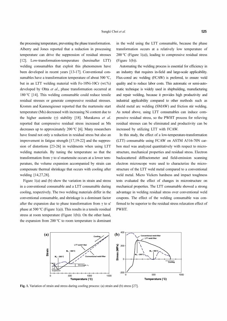
Figure 1(a) and (b) show the variation in strain and stress
in a conventional consumable and a LTT consumable during
cooling, respectively. The two welding materials differ in the
conventional consumable, and shrinkage is a dominant factor
after the expansion due to phase transformation from γ to α'
phase at 500 oC (Figure 1(a)). This results in a tensile residual
stress at room temperature (Figure 1(b)). On the other hand,
the expansion from 200 oC to room temperature is dominant
in the weld using the LTT consumable, because the phase
transformation occurs at a relatively low temperature of
200 oC (Figure 1(a)), leading to compressive residual stress
(Figure 1(b)).
Automating the welding process is essential for efficiency in
an industry that requires in-field and large-scale applicability.
Flux-cored arc welding (FCAW) is preferred, to ensure weld
quality and to reduce labor costs. This automatic or semi-auto-
matic technique is widely used in shipbuilding, manufacturing
and repair welding, because it provides high productivity and
industrial applicability compared to other methods such as
shield metal arc welding (SMAW) and friction stir welding.
As noted above, using LTT consumables can induce com-
pressive residual stress, so the PWHT process for relieving
residual stresses can be eliminated and productivity can be
increased by utilizing LTT with FCAW.
In this study, the effect of a low-temperature-transformation
(LTT) consumable using FCAW on ASTM A516-70N car-
bon steel was analyzed quantitatively with respect to micro-
structure, mechanical properties and residual stress. Electron
backscattered diffractometer and field-emission scanning
electron microscope were used to characterize the micro-
structure of the LTT weld metal compared to a conventional
weld metal. Micro Vickers hardness and impact toughness
tests evaluated the effect of changes in microstructure on
mechanical properties. The LTT consumable showed a strong
advantage in welding residual stress over conventional weld
coupons. The effect of the welding consumable was con-
firmed to be superior to the residual stress relaxation effect of
PWHT.
Fig. 1. Variation of strain and stress during cooling process: (a) strain and (b) stress [27].

526 대한금속 ·재료학회지 제59권 제8호 (2021년 8월)
2. Experimental Procedure
2.1 Materials and weld fabrication
A schematic layout of the welded coupons is shown in Fig. 2.
The chemical composition carbon equivalent (Ceq) of weld-
ing consumables and base metal is listed in Table 1, and their
mechanical properties are presented in Table 2. The carbon
equivalent of the welding materials can be calculated with
Eq. (1) [29].
(1)
Welding plates of ASTM A516-70N carbon steel were pre-
pared for a butt weld size of 300 mmw× 200 mml× 12 mmt
(two plates 150 mm wide were joined), which had a 60 o V-
groove geometry. Welding consumables with 1.2 mm diam-
eter, AWS E71T-1C [30] were used for the conventional
welding coupon and Mn-based LTT material for the LTT
welding coupon, were welded in four passes. Flux-cord arc
welding (FCAW) was performed with different welding con-
ditions and two welding consumables, as shown in Table 3.
Three FCAW coupons were fabricated, two with conven-
tional consumables and one with a Mn-based LTT consum-
able. One of the conventional welding coupons was post-
weld heat-treated as specified in ASME section III NX-4622
[31]. PWHT was performed at 635±15 oC for 12 hours after
welding, according to ASME section III NX-4622 [31], for
an additional conventional welding coupon.
2.2 Microstructure characterization and mechanical
properties
Cross-sectional samples of 10 mmw× 10 mml× 10 mmt
containing the fusion line were machined at the center of the
welding coupons from the LTT weld and the conventional
weld without PWHT. The samples were mechanically pol-
ished with 400-2400 grit paper and then a suspension with 1-
μm-diamond particles and 0.25-μm-colloidal silica. X-ray
diffractometer (D8-Advance, Bruker, Karlsruhe, Germany)
was used to detect the phases of the weld metal with the two
welding consumables using a Cu-Kα target, and a scanning
range and speed of 20 o to 100 o and 3 o/min, respectively.
The sample used for X-ray diffraction measurement was
chemically etched with 5% nital for microstructural obser-
vation. A field-emission scanning electron microscope (FE-
SEM, FEI Quanta 250 FEG, Hillsboro, OR, USA) was used
to identify the microstructures in the weld metal. Additional
Ceq CMn
6--------
Cr Mo V+ +( )
5--------------------------------
Ni Cu+( )
15----------------------+ + +=
Fig. 2. Schematic layout of welding coupons from (a) top view, (b)side view and Charpy impact test specimen.
Table 1. Chemical compositions and carbon equivalent (Ceq) of welding consumables and base material (wt-%)
C Si Mn O P S Fe Ceq
Conventional consumable 0.04 0.55 1.25 - 0.02 0.01 Bal. 0.25
Mn- LTT consumable 0.03 0.38 4.30 0.07 - - Bal. 0.75
Base metal (A516-70N) 0.31 0.15-0.40 0.85-1.20 - 0.03 0.03 Bal. 0.45-0.51
Table 2. Tensile properties of welding consumables and basematerial
Materials
Yield
strength
(MPa)
Tensile
strength
(MPa)
Elongation
(%)
Conventional consumable 520 580 23
Mn- LTT consumable 727 820 23
Base metal (A516-70N) 404 575 21
Table 3. Welding conditions for welding consumables
Welding
current
(A)
Arc
voltage
(V)
Welding
speed
(cm/min)
Heat
input
(kJ/cm)
Conventional consumable 240 30 22 20
Mn- LTT consumable 260 32 48 10

Sungki Choi et al. 527
surface preparation was made for electron backscattered dif-
fractometer (EBSD; EDAX-Hikari) analysis by electropol-
ishing in a mixed solution of 90% ethanol (C2H5OH) and
10% perchloric acid (HClO4) at 31 V for 30 s. EBSD anal-
ysis was operated at an acceleration voltage of 15 kV and a
working distance of 15 mm, and a step size of 2 μm. The
phase fraction in the weld metal with the LTT consumable
was analyzed quantitatively under this condition with a scan
area of 200 μm × 200 μm and a step size of 0.5 μm.
Microhardness testing was performed by Micro-AIS (Fron-
tics Inc., Seoul, Korea) with a Vickers indenter at fixed max-
imum load of 0.1 kgf. The hardness distribution over the
cross-section was measured from the weld center toward the
heat-affected zone (hereinafter HAZ). Two diagonal lengths of
the indent were directly measured by optical microscope. Three
sub-sized Charpy V-notch specimens (5 mm × 10 mm × 55 mm,
45 o) were extracted from the center of the weld line fol-
lowing ASME section II SA370 [32] in the direction trans-
verse from the welding plates, as shown in Fig. 2. The tests
were conducted at room temperature
2.3 Residual stress measurement
The residual stress of the LTT welding coupon was mea-
sured using X-ray diffraction prior to indentation testing to
compare the results of the two tests. An Xstress3000 (X-ray
Stress Analyzer) was used with Cr-Kα radiation (λ = 0.22911
nm), 2θ = 156.4 °, diffracting plane {211} from base metal
and weld metal. From Bragg’s Law, the sin2ψ method was
used for measurements. To measure the changes in lattice
spacing, the operating voltage was 30 kV and the current
6.7 mA. The measurements were carried out from the weld
center through the red line (Fig. 2) perpendicular to the weld-
ing line at 2 mm intervals.
Instrumented indentation testing (IIT) was performed for
residual stress measurement on the top surface of the three
welding coupons, carefully polished up to 2000 grit sand-
paper following ISO 14577-1 [33]. A commercial indentation
system, AIS 3000 (Frontics Inc., Korea) with a load reso-
lution of 0.05 N and depth resolution of 0.1 μm was used. A
Vickers indenter with an apex angle of 136 o [34] was used,
and all the tests were controlled with a maximum load of
490 N (50 kgf) and an indentation loading rate of 0.3 mm/
min. The measurements were performed at 4 mm intervals on
the red line, as well where the X-ray diffraction was per-
formed. The normality between the indenter and the spec-
imen surface was carefully controlled not to exceed 1 degree.
The model developed by Lee and Kwon was used for
residual stress evaluation [35]. The indentation load-depth
curve is shifted depending on the sign and magnitude of the
residual stress relative to the curve in the stress-free state.
The relation between the force difference as a result of resid-
ual stress and the deviatoric stress of the indenting direction
was formulated with the projected area as Eq. (2).
(2)
where L0 and Ls are the loads in the stress-free and stressed
state, respectively, and As means indentation contact area.
3. Results and Discussion
3.1 Microstructure characterization
The microstructure of the LTT weld metal was charac-
terized by X-ray diffraction, FE-SEM and EBSD, and then
compared to the conventional weld metal without PWHT.
The X-ray diffraction peaks of the two weld metals (except
the conventional weld metal with PWHT, since phase trans-
formation does not generally occur with PWHT) are com-
pared in Fig. 3. Both weldments had phases suspected to be
ferrite or bainite/martensite showing a bcc structure in the
σresidual 3L0 Ls–( )
As
-------------------⋅=
Fig. 3. Results of XRD in weld metal of conventional and LTTconsumable.

528 대한금속 ·재료학회지 제59권 제8호 (2021년 8월)
weld metal. No retained austenite phase was detected by X-
ray diffraction analysis; it rarely forms when the carbon con-
tent is less than 0.4 wt% [36], as was the cases in these two
weldments.
Figure 4 shows the weld metal images obtained from FE-
SEM at ×800, ×1500 and ×3000 magnitude. Ferrite phases
(acicular, allotriomorphic, and Widmanstätten) were observed
in the weld metal with the conventional consumable, as pre-
viously reported [37,38]. And, in case of the weldment with
the LTT, mixed structures of ferrite, bainite, and martensite
were detected. These results correspond to those of the X-ray
diffraction peak analyses.
For more depth-in-analysis of phases in the conventional
and LTT welding, the effective grain size and phase fraction
of the weld metals was measured by EBSD analysis. Figure
5 shows the IQ map of the weld metals. The average effec-
tive grain size can be calculated by defining a misorientation
angle larger than 15 o [39,40]. The average effective grain
sizes were 6.70 μm and 5.49 μm for the conventional and
LTT consumable, respectively. It was estimated that the max-
imum temperature during welding of the conventional con-
sumable was higher than the LTT consumable, and LTT’s
finer effective grain size affected the hardness and impact
toughness.
GOS map and Gaussian fitting graph from IQ analysis
using EBSD were performed for the LTT consumable, since
the phases were difficult to distinguish accurately using only
XRD and FE-SEM. The fraction of martensite phase in the
weld metal of the Mn-based LTT consumable was distin-
guished by analyzing the grain orientation spread (GOS) map
and IQ map from the EBSD results. Low-angle and high-
angle boundaries were divided by ranges into 2 ° < θ < 15 °
and θ > 15 ° [41] and are indicated in Fig. 6(a) as red and
Fig. 4. FE-SEM Micrographs in weld metal of sample welded with (a) conventional and (b) LTT consumables.
Fig. 5. IQ map of sample welded with (a) conventional and (b) LTTconsumables in weld metal.

Sungki Choi et al. 529
blue lines, respectively. Ferrite can be identified in the GOS
map, having a tolerance angle of 15 ° and a misorientation
angle less than 5 ° [42]; it is represented by the yellow region
in Fig 6(a). After eliminating the ferrite phase, bainite and
martensite phases can be distinguished by Gaussian fitting
the graph from IQ analysis [36]. In general, the martensite
phase has larger lattice imperfections than the bainite phase,
and thus has lower Kikuchi pattern intensity, which in turn
results in lower contrast than the bainite phase [36].
Since the IQ value is affected by many operating factors
including image condition, it should be normalized to min-
imize error effects. The normalized IQ value can be repre-
sented by Eq. (3) [43]:
(3)
where IQN is the normalized IQ value and IQinitial is the value
obtained directly from experiment; IQMax and IQMin are the
maximum and minimum IQ values.
Figure 6(b), showing the fraction of the normalized IQ
value, can be separated into two distributions by Gaussian fit-
ting. The red distribution of IQ values with relatively low
contrast represents the martensite phase, and the other dis-
tribution of IQ values with high contrast on the right can be
identified as the bainite phase.
The phase fractions of ferrite, austenite, martensite and
bainite were 50.5%, 0.2%, 40.2% and 9.1%, respectively.
The fraction of martensite is considered a major factor affect-
ing the mechanical properties (strength, hardness and tough-
ness) and residual stresses.
3.2 Micro Vickers hardness and impact toughness
Micro Vickers hardness was evaluated at 1 mm intervals
from the weld center to the base metal in the transverse direc-
tion for a cross section about 1 mm from the top surfaces of
the welding coupons. Similar levels of hardness in the HAZ
and base metal were measured as shown in Fig. 7, whereas
average hardness values in the weld metal showed a dif-
ference, with 216.8 Hv in the conventional consumable and
314.5 Hv in the LTT consumable. Martensite in the LTT
weld metal is reasonably considered a major cause of the
higher hardness distribution.
The average values of impact absorption energy for the
IQN
IQInitial IQMin–
IQMax IQMin–--------------------------------- 100×=
Fig. 6. (a) GOS map (Red and blue lines are low angle grain boundary and high angle grain boundary, respectively) and (b) Normalized IQGaussian distribution of sample welded with LTT consumable in weld metal.
Fig. 7. Results of micro hardness (0.1 kgf) distribution of weldmentin the cross-section.
530 대한금속 ·재료학회지 제59권 제8호 (2021년 8월)
conventional weld were 174.3±13 J and 53.3±3 J for the LTT
weld. The large difference in impact absorption energy can
be explained by microstructure: the greater fraction of acic-
ular ferrite in the material increases impact toughness [44]
and finer effective grain size decreases impact toughness
[45].
Martensite or martensite-austenite is the main factor deter-
mining absorption energy at room temperature, because
cracks can initiate due to stress concentrations around a hard
phase. The absorption energy can be lower with the higher
phase fractions [45,46]. With a conventional consumable,
acicular ferrite is distributed and martensite is not present in
the weld metal. However, when the LTT consumable was
used, a considerable martensite phase was distributed. The
presence of these phases influences the difference in impact
toughness between the two weldments.
3.3 Residual stress distribution
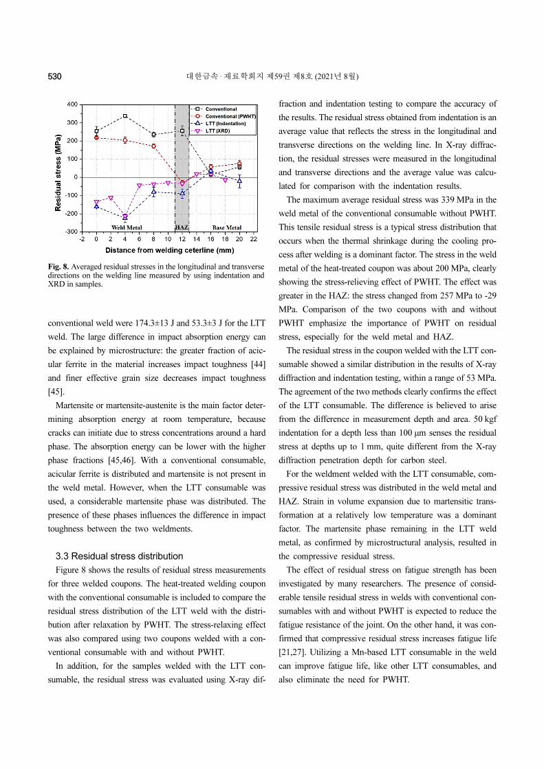
Figure 8 shows the results of residual stress measurements
for three welded coupons. The heat-treated welding coupon
with the conventional consumable is included to compare the
residual stress distribution of the LTT weld with the distri-
bution after relaxation by PWHT. The stress-relaxing effect
was also compared using two coupons welded with a con-
ventional consumable with and without PWHT.
In addition, for the samples welded with the LTT con-
sumable, the residual stress was evaluated using X-ray dif-
fraction and indentation testing to compare the accuracy of
the results. The residual stress obtained from indentation is an
average value that reflects the stress in the longitudinal and
transverse directions on the welding line. In X-ray diffrac-
tion, the residual stresses were measured in the longitudinal
and transverse directions and the average value was calcu-
lated for comparison with the indentation results.
The maximum average residual stress was 339 MPa in the
weld metal of the conventional consumable without PWHT.
This tensile residual stress is a typical stress distribution that
occurs when the thermal shrinkage during the cooling pro-
cess after welding is a dominant factor. The stress in the weld
metal of the heat-treated coupon was about 200 MPa, clearly
showing the stress-relieving effect of PWHT. The effect was
greater in the HAZ: the stress changed from 257 MPa to -29
MPa. Comparison of the two coupons with and without
PWHT emphasize the importance of PWHT on residual
stress, especially for the weld metal and HAZ.
The residual stress in the coupon welded with the LTT con-
sumable showed a similar distribution in the results of X-ray
diffraction and indentation testing, within a range of 53 MPa.
The agreement of the two methods clearly confirms the effect
of the LTT consumable. The difference is believed to arise
from the difference in measurement depth and area. 50 kgf
indentation for a depth less than 100 μm senses the residual
stress at depths up to 1 mm, quite different from the X-ray
diffraction penetration depth for carbon steel.
For the weldment welded with the LTT consumable, com-
pressive residual stress was distributed in the weld metal and
HAZ. Strain in volume expansion due to martensitic trans-
formation at a relatively low temperature was a dominant
factor. The martensite phase remaining in the LTT weld
metal, as confirmed by microstructural analysis, resulted in
the compressive residual stress.
The effect of residual stress on fatigue strength has been
investigated by many researchers. The presence of consid-
erable tensile residual stress in welds with conventional con-
sumables with and without PWHT is expected to reduce the
fatigue resistance of the joint. On the other hand, it was con-
firmed that compressive residual stress increases fatigue life
[21,27]. Utilizing a Mn-based LTT consumable in the weld
can improve fatigue life, like other LTT consumables, and
also eliminate the need for PWHT.
Fig. 8. Averaged residual stresses in the longitudinal and transversedirections on the welding line measured by using indentation andXRD in samples.

Sungki Choi et al. 531
4. Conclusions
In this study, the effect of welding consumables (Mn-based
LTT and conventional) and PWHT for FCAW-welded ASTM
A516-70N carbon steel was analyzed in terms of micro-
structure, mechanical properties and residual stress. The con-
clusions are summarized as:
(1) The microstructures containing acicular ferrite, allotri-
omorphic ferrite, and Widmanstätten ferrite were distributed
in the weld metal with the conventional consumable. In the
Mn-based LTT consumable weld metal, ferrite, austenite,
martensite, and bainite were identified in fractions of 50.5%,
0.2%, 40.2% and 9.1%, respectively, by GOS mapping and
normalized EBSD image quality analysis.
(2) The average hardness in the weld metal was 216.8 HV
in the conventional consumable and 314.5 HV in the LTT
consumable; likewise, the absorption energy from Charpy V-
notch testing was 174.3 J and 53.3 J, respectively. For the
LTT consumable, the relatively higher hardness and lower
absorption energy than the conventional consumable are
attributed to the finer effective grain size and the martensite
phase.
(3) The residual stress distribution with the LTT consum-
able was double-checked using two methods, instrumented
indentation and X-ray diffraction. The residual stress distri-
butions obtained with both methods showed a similar trend
within a range of 53 MPa difference.
(4) Considerable tensile residual stresses were distributed
in the coupons with the conventional consumable. PWHT
considerably decreased the magnitude of residual stress in the
weld metal and the HAZ, especially the HAZ, from 257 MPa
to -29 MPa. Compressive residual stress was identified in the
weld metal and HAZ when the LTT consumable was used,
and this can be presented as the main advantage of the low-
transformation-temperature welding consumables.
Acknowledgements
This work was supported by POSCO and the Korea Insti-
tute of Energy Technology Evaluation and Planning (KETEP)
and the New Faculty Startup Fund from Seoul National Uni-
versity for S.-K. K.
REFERENCES
1. H. Murakawa, M. Béreš, C. M. Davies, S. Rashed, A. Vega,
M. Tsunori, K. M. Nikbin, and D. Dye, Sci. Technol. Weld.
Join. 15, 393 (2010).
2. D. Deng and H. Murakawa, Comput. Mater. Sci. 78, 55
(2013).
3. G. A. Webster and A. N. Ezeilo, Int. J. Fatigue 23, 375
(2001).
4. S. Zabeen, M. Preuss, and P. J. Withers, Acta Mater. 83, 216
(2015).
5. H. J. Lee, S. Oh, and H. Kim, Korean J. Met. Mater. 57, 51
(2019).
6. H. Murakawa, M. Béreš, A. Vega, S. Rashed, C. M. Davies,
D. Dye, and K. Nikbin, Trans. JWRI 37 (2008).
7. D. J. Smith and S. J. Garwood, Int. J. Press. Vessels Pip. 51,
241 (1992).
8. J. S. Porowski, W. J. O'Donnell, M. L. Badlani, and E. J.
Hampton, Nucl. Eng. Des. 124, 91 (1990).
9. J. Altenkirch, A. Steuwer, M. J. Peel, P. J. Withers, S. W.
Williams, and M. Poad, Metall. Mater. Trans. A 39, 3246
(2008).
10. G. Hammersley, L. A. Hackel, and F. Harris, Opt. Lasers.
Eng. 34, 327 (2000).
11. Hyeonuk Park, Junhyung Kim, Youngsik Pyun, Amanov
Auezhan, Yoon Suk Choi, Met. Mater. Int. 25, 606 (2019).
12. WKC. Jones and PJ. Alberry, Met. Technol. 11, 557 (1977).
13. J. Altenkirch, J. Gibmeier, A. Kromm, T. Kannengiesser, T.
Nitschke-Pagel, and M. Hofmann, Mater. Sci. Eng. A 528,
5566 (2011).
14. A. Ohta, N. Suzuki, Y. Maeda, K. Hiraoka, and T.
Nakamura, Int. J. Fatigue 21, S113 (1999).
15. W. Wang, L. Huo, Y. Zhang, D. Wang, and H. Jing, J. Mater.
Sci. Technol. 18, 527 (2002).
16. P. P. Darcis, H. Katsumoto, M. C. Payares-Asprino, S. Liu,
and T. A. Siewert, Fatigue Fract. Eng. Mater. Struct. 31,
125 (2008).
17. S. Zenitani, N. Hayakawa, J. Yamamoto, K. Hiraoka, Y.
Morikage, T. Kubo, K. Yasuda, and K. Amano, Sci.
Technol. Weld. Join. 12, 516 (2007).
18. A. Kromm and T. Kannengiesser, Soldag. insp. 14, 82
(2009).
19. A. Ota, C. Shiga, Y. Maeda, N. Suzuki, O. Watanabe, T.
Kubo, K. Matsuoka, and S. Nishijima, Weld. Int. 14, 801
(2000).
532 대한금속 ·재료학회지 제59권 제8호 (2021년 8월)
20. J. Eckerlid, T. Nilsson, and L. Karlsson, Sci. Technol. Weld.
Join. 8, 353 (2003).
21. A. Ohta, N. Suzuki, Y. Maeda, and S. J. Maddox, Weld.
World 47, 38 (2003).
22. E. Harati, L. Karlsson, L.-E. Svensson, and K. Dalaei, Int. J.
Fatigue 97, 39 (2017).
23. H. K. D. H. Bhadeshia, Math. Modell. Weld Phenom. 2, 71
(1995).
24. Y. Mikami, Y. Morikage, M. Mochizuki, and M. Toyoda,
Sci. Technol. Weld. Join. 14, 97 (2009).
25. A. Kromm, J. Dixneit, and T. Kannengiesser, Weld. World
58, 729 (2014).
26. X. Chen, P. Wang, Q. Pan, and S. Lin, Cryst. 8, 293 (2018).
27. Z. Barsoum and M. Gustafsson, Eng. Fail. Anal. 16, 2186
(2009).
28. H. K. D. H. Bhadeshia, Mater. Sci. Eng. A 378, 34 (2004).
29. IIW/IIS DOC. 452-74. Weld World 12, 65 (1974).
30. AWS—A5.20/A5.20M:R2015 Carbon Steel Electronics for
Flux Cored Arc Welding; (AWS: Miami, FL, USA, 2015).
31. ASME Section III, NX, "Rules for Construction of Nuclear
Facility Components", ASME, 2010.
32. ASME Boiler and Pressure Vessel Code, Section II SA-370,
2015.
33. ISO/FDIS 14577-1: Metallic materials - Instrumented
indentation test for hardness and material parameter, Part 1:
Test method. (International Organization for Standardization,
Geneve, Switzerland, 2002).
34. ASTM E2546-15: Standard Practice for Instrumented
Indentation Testing (ASTM International, 2015).
35. Y.-H. Lee and D. Kwon, Acta Mater. 52, 1555 (2004).
36. M.-S. Baek, K.-S. Kim, T.-W. Park, J. Ham, and K.-A. Lee,
Mat. Sci. Eng. A 785, 139375 (2020).
37. M. Abbas, A. S. Hamdy, and E. Ahmed, Mater. Res.
Express 7, 036523 (2020).
38. T. W. Shin, J. H. Hyun, and J. H. Koh, J. Weld. Join. 35, 68
(2017).
39. N. J. Kim and Y. G. Kim, Mater. Sci. Eng. A 129, 35 (1990).
40. Y. Ohmori, H. Ohtani, and T. Kunitake, Met. Sci. 8, 357
(1974).
41. N. Isasti, D. Jorge-Badiola, M. Taheri, B. López, and P.
Uranga, Metall Mat Tras. 42, 3729 (2011).
42. S.-I. Lee, T.-W. Hong, and B. Hwang, Korean J. Mater. Res.
27, 636 (2017).
43. J. Wu, P. J. Wray, C. I. Garcia, M. Hua, and A. J. Deardo,
ISIJ Int. 45, 254 (2005).
44. L. Svensson and B. Gretoft, Weld. J. 69, 454 (1990).
45. S.-W. Lee, S.-I. Lee, and B. Hwang, Korean J. Met. Mater.
58, 293 (2020).
46. N. Huda, A. R. H. Midawi, J. Gianetto, R. Lazor, and A. P.
Gerlich, Mater. Sci. Eng. A 662, 481 (2016).