effect of inclination angle on the response of double-row
TRANSCRIPT

1150 Technical Gazette 27, 4(2020), 1150-1159
ISSN 1330-3651(Print), ISSN 1848-6339 (Online) https://doi.org/10.17559/TV-20200408155204 Original scientific paper
Effect of Inclination Angle on the Response of Double-row Retaining Piles: Experimental and Numerical Investigation
Jinbi YE, Chenfei WANG, Weipeng HUANG, Jing ZHANG, Xianqi ZHOU
Abstract: The excavation depth of foundation pits has been increasing along with the continuous development of underground space and high-rise buildings. As a result, traditional double-row vertical piles cannot meet the ground settlement and deflection requirements. This study proposed a double-row pile optimization method to extend the suitability of double-row retaining piles to greater excavation depth. The optimization model was established by adjusting the inclination angle of the front and rear piles. Physical scale model tests were performed to analyze the effect of the inclination angle on the pile head displacements and bending moments during excavations and step loadings using three schemes, namely, traditional double-row piles with vertical piles, double-row contiguous retaining piles with batter pile in the front row, and double-row contiguous retaining piles with batter pile in both rows. Numerical simulations were also conducted to verify the effectiveness of the inclination angle adjustment in optimizing the double-row piles. Results indicate that the increase in the displacement and bending moment of the double-row contiguous retaining batter piles is not evident during excavation and step loading when compared with those of the double-row vertical piles and the double-row contiguous retaining piles with batter pile in the front row. Thus, double-row contiguous retaining batter piles can be used in deep foundation pits. The tilt angle is also excessively small to reduce the lateral displacement of the foundation pit, and the optimal tilt angle is 8° – 16°. Although the embedment depth can influence the deformation of the double-row contiguous retaining batter piles significantly, a critical embedment depth may be reached. The findings of this study can provide references for the optimization of double-row piles in foundation pits.
Keywords: double-row contiguous retaining batter piles; foundation pit; inclination angle; optimization method; physical model test
1 INTRODUCTION
At present, the excavation depth of foundation pits has become increasingly large along with the continuous development of underground space and high-rise buildings. Although deep excavation is temporary, underestimating its importance yields adverse consequences. The ground settlement and deflection of the supporting structure are the two major criteria of the foundation pit design [1]. Excessive ground settlement can affect the function of the surrounding buildings and pipelines, even cause collapse [2]. In addition, the presence of buildings, vehicles, and other forms of surcharge loading on the ground causes additional stress [3, 4] to the supporting structure, thereby increasing the deflection and ground settlement. The shear strength and loading path of soil will also affect the stability of foundation pit [5-8].
The double-row pile support structure is a novel supporting structure that is composed of a front pile, a rear pile, and a crossbeam. Unlike single-row piles, the lateral stiffness of the double-row piles is enhanced because of spatial effects, thereby increasing lateral resistance and reducing deformation. Therefore, the double-row pile support structure is widely used in foundation engineering and the excavation depth is approximately 10 m [9]; as the excavation depth of the foundation pit increases, the applicability of the double-row pile declines because of its large deflection and internal force, which hardly meet engineering requirements. Therefore, effective and suitable supporting structures should be developed.
Batter piles convert a part of the load into axial pressure or tension when resisting horizontal load and have higher horizontal resistance than vertical piles [10]. However, batter piles are prefabricated, thereby hindering their application in onshore engineering. At present, batter piles can be driven in foundation pits, and their applicability in engineering gradually improved with the development of construction machinery [11]. As an alternative to single-row contiguous retaining batter piles,
oblique-straight alternate piles have also exhibited rapid development [12]. However, it cannot promote the spatial effects fully because of the small row spacing. Therefore, oblique-straight alternate piles are not the optimal choice.
The analysis shows that the traditional double-row vertical piles and oblique-straight alternate piles fail to meet the requirements of deep excavations. Few scholars have investigated the risky surcharge loading [4] of double-row piles.
This work mainly aims to investigate the effect of the inclination angle on the response of double-row retaining piles. Subsequently, the optimal pile layout is selected through physical scale model tests and numerical simulations. Three types of double-row piles, namely, double-row vertical piles, double-row contiguous retaining piles with batter pile in the front row, and double-row contiguous retaining batter piles, are evaluated in the physical scale model tests. The pile head displacements and bending moments during excavations and step loadings are measured using the displacement meters and strain gauges installed on the piles. Similar numerical examples of double-row piles are also provided to verify the physical scale model tests using the explicit finite difference software FLAC3D. The variations in the lateral deformation are determined through numerical simulations by changing the parameters, including the inclination angle and the embedment depth. The reasonable inclination angle values and some suggestions with consideration of the deflection are proposed for the design of double-row piles as a retaining structure.
2 STATE OF THE ART
Many scholars have performed numerous studies on double-row piles in foundation pits. Cao et al. [13] provided an equivalent truss model considering the shear deformation effect of soil between the piles and the pile-soil interface friction. However, the soil pressure of this

Jinbi YE et al.: Effect of Inclination Angle on the Response of Double-row Retaining Piles: Experimental and Numerical Investigation
Tehnički vjesnik 27, 4(2020), 1150-1159 1151
model was assumed to be Rankine's Earth pressure, which may be different from the actual earth pressure distribution.
Peng et al. [14] investigated the effect of row spacing on the double-row piles in deep foundation pits through physical model tests. The results showed that row spacing greatly affected the behavior of double-row piles. Moreover, the effect on the back row was greater than that of the front row. The optimal row spacing was 3 - 4 times the diameter of the pile. However, the influence of the pile tilt on the double-row piles was neglected. To reflect the pile-soil interaction thoroughly, Wang et al. [9] used PLAXIS3D to establish a real 3D finite element model of double-row piles, and their spatial effects on the entire foundation pit was considered. The results showed that the soil pressures among the piles and below the excavation face are close to Rankine's active and static earth pressures, respectively. The lateral deformation and bending moment in the middle of the long side of the foundation pit is larger than that at the corner. The surcharge loading effect, however, was disregarded in the model. Fall et al. [15] reported the application case of the double-row sheet pile wall in deep foundation pits near the subway lines. The results of the numerical calculation and field measurement demonstrated that the deformation of the foundation pit of the double-row sheet pile wall is relatively small. However, the corresponding internal force was not provided.
The excavation of foundation pits and the surrounding structures poses mutual effects. The adjacent surcharge loading of the surrounding ground may increase the deformation of the foundation pit and even cause collapse, and the excavation of the foundation pit may induce adverse consequences, such as the tilting of adjacent buildings. Therefore, many scholars have analyzed the interaction between the excavations of the foundation pit and those of the surrounding grounds. With regard to the influence of surcharge loading on the foundation pit, Liu et al. [4] performed field monitoring and numerical simulation to study the influence of the asymmetric load of vehicles on deep foundation pits beside the highway. The results indicated that vehicular loads can seriously influence the response of deep excavation. However, deep excavation was supported by bored piles with one and seven levels of reinforced concrete and steel pipe struts. Single-row piles with a diameter of 1.2 m and a spacing of 1.5 m, which are not economically efficient, are used in the project. Singh et al. [1] conducted a pseudostatic analysis of the settlement and deflection of cantilever sheet pile walls under earthquake surcharge loading using the finite difference software FLAC. The findings indicated that the deflection and settlement of these walls increase with the horizontal seismic acceleration coefficient and decrease with the increase in the distance between the surcharge loading and the top of the wall. This study mainly investigated the cantilever sheet pile wall using a 2D model. Nisha et al. [16] reported a deep excavation for an office building in Bengaluru, India to investigate the influence of excavation on the surrounding structures. The uncertainty of the construction led to the collapse of a foundation pit with an excavation depth of 20 m, which may cause large deformation to adjacent high-rise buildings. Therefore, necessary measures were implemented immediately to remedy the situation. Soomro et al. [17] used ABAQUS to analyze the effect of
excavation on the adjacent loaded single floating pile considering the excavation depth, pile head boundary conditions, and working loads. However, parameters, such as pile length, diameter, and distance from the edge of the foundation pit, were not considered. Shakee et al. [18] studied a 2 × 2 floating pile group located adjacent to a deep soft clay excavation. The influences of the excavation depth, pile length, pile group location (from excavation), supporting system's stiffness, soil state and permeability, and working load, were investigated using a finite element model. The excavation depth was 20 m, and the underground diaphragm wall was 1.0 m thick and 40 m deep. A total of 10 struts were used in the project. However, the relationship between the deformations of the underground diaphragm wall and the floating pile group was not quantified. However, among the aforementioned studies, only few analyzed the interaction between the double-row pile support foundation pits and the surrounding structures.
In the study of batter piles, Goit et al. [19] applied lateral harmonic loadings to the pile heads of vertica l, 5°, and 10° batter piles in noncohesive soil. The horizontal impedance functions of the inclined single piles were measured experimentally. However, this study focused on a single batter pile, and the load was applied to the pile head. Jeyapriya et al. [20] conducted laboratory tests to study the behaviour of the vertical and batter pile groups under the coupling effect of the vertical and lateral loads in sand. Similar to the previously mentioned study, the load was applied to the pile head. The diameter of the model pile was only 8 mm, and the scale effect cannot be ignored. Pankaj et al. [21] applied lateral, uplift, and combined loads to vertical and batter pile groups in a model test and discovered that the negative batter pile with a length-to-diameter ratio of 38 and an inclination angle of 35° exhibited the largest bearing capacity under various load conditions. Ghazavi et al. [22] proposed an analytical solution to explore the static pile-soil-pile interaction of two pile groups, where the piles and the soil medium were assumed to be linearly elastic. The pile-soil-pile interaction coefficient was defined as the additional head displacement of the second pile obtained from dividing the first pile by the head displacement of the first pile. The results revealed that the interaction among the batter piles decreases with the increase in pile spacing and inclination. However, due to the assumption that the pile and soil are elastic, the plasticity of the latter was disregarded. Ghasemzadeh et al. [23] studied the interaction among batter piles; discussedthe coupling effects between axial and lateral loads; andanalyzed the influence of the batter angle, slendernessratio, pile spacing, pile-soil stiffness ratio, and soilplasticity on the interaction coefficient using ABAQUS.However, the relationship between the ultimate bearingcapacity and the inclination of the batter pile group was notanalyzed.
Few studies focused on the use of batter piles in foundation pit retaining structures. Seo et al. [11] developed a retaining structure using front supports and batter piles. Finite element analysis and field test were conducted to verify the applicability of the batter piles. The results showed that batter piles could control the displacement effectively. However, this type of structure

Jinbi YE et al.: Effect of Inclination Angle on the Response of Double-row Retaining Piles: Experimental and Numerical Investigation
1152 Technical Gazette 27, 4(2020), 1150-1159
does not fully utilize spatial effects, and the bending moment at the top of the pile is large.
The aforementioned studies mainly focused on double-row vertical piles, batter piles with load at the pile head, and single-row inclined-braceless retaining wall. The studies on raking piles in foundation pits are scarce, especially double-row contiguous retaining batter piles. The present study conducted physical scale model test and numerical simulation to compare the behaviours of double-row vertical pile, double-row contiguous retaining pile with batter pile in the front row, and double-row contiguous retaining batter piles. The characteristics of the double-row contiguous retaining batter piles at different inclination angles and embedment depths were also discussed. This work is expected to improve our understanding of double-row piles in deep excavations and provide design references to engineers.
The remainder of this study is organized as follows. Section 3 presents the methodology, including the physical scaling model tests and numerical simulations. Section 4 discusses the results of the tests and the simulations, as well as the influence of tilt angle and embedment depth on the behaviour of double-row contiguous retaining batter piles. The last section provides the summary and conclusions.
3 METHODOLOGY 3.1 Subtitle 1 (Writing Instructions)
Model tests have been frequently used in geotechnical engineering and are important in understanding the complex behaviour of prototypes. Physical models are more preferred than full-scale field tests because of their flexibility and ease of application under loading conditions.
3.1.1 Model Preparation
The response obtained from the model tests is different from that obtained from the prototype. Thus, a set of scaling relations is necessary to correlate both responses. According to the physical scaling law, the model test should reflect the actual situation of the prototype. The pile length L, material properties (E, μ, ρ), section characteristics (A, I, W), internal force (M, N), section stress σ, and strain ε are important physical parameters in the simulation of pile. The pile model satisfies the similarity of the bending stiffness [24]. Tab. 1 summarizes the scaling relationships used in this study, where λ is the geometric scaling ratio of the model to the prototype. According to the size of the experimental groove (length × width × height = 1000 × 400 × 900 mm) (Fig. 1) and the scaling law, λ = 1:25.
Table 1 Model-prototype scaling relations Parameters Symbol Scaling factors
Length L λ Flexural rigidity EI λ5 Strain ε 1 Density γ 1
The excavation depth of the prototype foundation pit is 10 m. The pile diameter, pile length, and distance between the prototype piles are 0.8, 17.5, and 2.5 m, respectively. After scaling, the corresponding parameters for the model are 400, 32, 700, and 100 mm, respectively. PVC pipes with outer and inner diameters of 32 and 27.2 mm, respectively, are used as a model pile, and the hollow part of the pipe was filled with calcined gypsum with a gypsum mix ratio of 1.1:1. The calculation results demonstrate that the model pile satisfies the flexural rigidity similarity.
Figure 1 Schematic of the physical scale model (unit: mm)
3.1.2 Model Test Device
The test device is composed of an experimental groove, a loading frame, double-row model piles, and a soil medium.
(1) Experimental groove. The experimental groove,which had the dimension of 1000 (length) × 400 (width) × 900 (height) mm, was welded using steel plates.
(2) Loading frame. A self-designed loading frame wasequipped with guide rails to ensure that the load was vertically downward.

Jinbi YE et al.: Effect of Inclination Angle on the Response of Double-row Retaining Piles: Experimental and Numerical Investigation
Tehnički vjesnik 27, 4(2020), 1150-1159 1153
(3) Double-row model piles. As previously mentioned,the model pile was simulated using a PVC pipe filled with plaster. Strain gauges were pasted on the outer surface of the model pile, and seven monitoring points were installed 50 mm from the top of the pile with an interval of 100 mm. A total of 28 strain gauges were installed to monitor the bending behavior of the double-row piles.To ensure the connection validity, the front and back piles were connected using wooden boards with a thickness of 18 mm, length of 380 mm, and width of 250 mm. Plywood pieces with a thickness of 0.5 mm were arranged at the back of the front row pile to prevent the soil between the pile rows from being squeezed out during the test.
(4) Soil medium. The soil media below and above thebottom of the excavation is lateritic clay and standard quartz sand, respectively. The lateritic clay was excavated from the foundation pit of the administrative building of Xiamen University of Technology, whereas the standard sand was the International Organization for Standardization (ISO) standard quartz sand produced in Xiamen. The water content, bulk density, cohesion and friction angle of the lateritic clay and standard quartz sand are 3.5%, 15.8 kN/m3, 0 kPa, 22° and 8.2%, 18.4 kN/m3, 30 kPa, 20°, respectively.
Table 2 Test schemes No. Description Row spacing at the pile
head D / mm Inclination of front
row pile α1 / ° Inclination of rear
row pile α2 / ° Pile spacing S /
mm Case 1 Conventional double-row vertical piles 100 0 0 100 Case 2 Double-row piles with batter pile in the front row 100 8 0 100 Case 3 Double-row batter piles 100 8 8 100
3.1.3 Model Test Schemes
Three model tests with different pile arrangements, namely, double-row vertical piles, front-row inclined double-row piles and double-row batter piles, were performed. According to previous research [13, 25], the cost-efficient centre-to-centre distance and row distance are both approximate 4 times of pile diameter. Thus, the pile distance in row and row distance were 100 mm, 3.3 times of the pile diameter. The test schemes are summarized in Tab. 2, and the profile of the model test is illustrated in Fig. 2.
Figure 2 Experimental setup with different layouts
3.1.4 Test Procedures
The side wall was lubricated to reduce the boundary effect of the experimental groove. Petroleum jelly was initially applied on the side wall. Then, two layers of plastic film with a small coefficient of friction were used as covers. Soil filling was performed in two sections: filling of lateritic clay below the bottom of the excavation and filling of the standard quartz sand above the bottom of the excavation. The lateritic clay was filled layer by layer, and each layer was 20 mm thick. A 2 kg rubber hammer was used, and the drop distance was 40 cm. The standard quartz sand was filled using the air pluviation method [26] and reproducible density was achieved. Each filling layer was
10 mm thick, and the drop distance was 40 cm. The compactness of the soil in the different test schemes was the same. The soil was then consolidated for 2 days before the test.
Figure 3 Experimental process
The test procedure was divided into two stages. The first stage refers to the excavation of the foundation pit. The excavation depth was 400.0 mm, and the excavation process was completed within three times, with an

Jinbi YE et al.: Effect of Inclination Angle on the Response of Double-row Retaining Piles: Experimental and Numerical Investigation
1154 Technical Gazette 27, 4(2020), 1150-1159
excavation depth of 133.3 mm each time. Manual excavation was implemented, and the soil near the pile was excavated carefully to avoid disturbance. Excavations were performed every 2 hours. The next stage was the step loading, which was performed 100.0 mm away from the center of the rear-row pile. The load of each stage was 0.2 kN, and the next level was applied after the load had been stabilized for 60 minutes. The tests aimed to compare the ultimate bearing capacity of the three layouts of double-row piles, thus, the step loads were applied until the double-row piles failed. The test process is shown in Fig. 3.
3.2 Numerical Model
The explicit 3D finite difference code FLAC3D was used to explore the behavior of double-row batter piles further.
3.2.1 Basis of Modeling
The pile, the coupling beam, and the soil were simulated through solid elements, whereas the pile-soil interaction was simulated using interface elements. The size of the model is larger than the tested experimental models to avoid the boundary effects on the response of the piles. The size selected for the model is 2.4 × 0.4 × 1.2 m. The geometry and mesh of the model are shown in Fig. 4. The nonlinear behaviour of soil was modelled using Mohr-Coulomb failure criteria, and the pile was modelled as a linear elastic material [9, 24]. The two layers of soil were assumed to be homogeneous and isotropic. As previously described, the model pile used in the tests comprises a PVC
pipe injected with gypsum. To simplify the simulation, the equivalent Young's modulus for the model pile was adopted. The material parameters in the numerical simulation are listed in Tab. 3.
Figure 4 3D mesh and boundary conditions adopted in this study
3.2.2 Boundary Conditions and Calculation Process
The boundary conditions adopted in this analysis are illustrated in Fig. 4. With regard to displacement boundary conditions, the gridpoints at the side boundaries of the mesh were constrained horizontally, whereas the gridpoints at the base were fixed in all directions. The top of the model was allowed to move in any direction.
FLAC3D first generated the initial vertical stresses that were in equilibrium with the self-weight of the soil. After three excavations, the uniformly distributed step loadings were applied to the surface of the model.
Table 3 Material parameters in the numerical simulation Material Young's modulus/MPa Poisson's ratio Frictional angle /° Cohesion /kPa Density/ kg/m3
Soil (ISO standard sand) 10 0.32 22 0.05 15.8 Soil (lateritic clay) 25 0.25 20 30 18.4 Supporting pile 8300 0.2 - - 24.0 Pile cap 10000 0.2 - - 20
4 RESULTS AND DISCUSSIONS 4.1 Experimental Results
The lateral displacement of the pile head and the bending moment of the pile shaft were obtained on the basis of the physical scaling model test in Section 3.1.
The pile head displacements during excavation are shown in Fig. 5a. The horizontal displacement in the three cases increased approximately linearly during excavation, with the fastest increases exhibited by Case 1. During the entire excavation process, the displacement increase rates in Cases 2 and 3 were smaller than those in Case 1.
Figure 5 Curves of the lateral displacement versus the (a) excavation step and (b) vertical load for the model pile head

Jinbi YE et al.: Effect of Inclination Angle on the Response of Double-row Retaining Piles: Experimental and Numerical Investigation
1155 Technical Gazette 27, 4(2020), 1150-1159
The load-displacement curve of the step loading process is shown in Fig. 5b. To reflect the effect of step loadings on the lateral displacement of the pile head, the pile head displacement after the excavation was set to zero. The curve can be divided into three stages. The first stage was a slow development stage. When the load is not more than 0.6 kN, the lateral displacements of the pile head in the three cases were small, and the maximum displacement was observed in Case 1. The second stage was the rapid development stage, wherein as the load increased from 0.6 kN to 1.2 kN, the lateral displacement of the pile head rapidly increased. The last stage was the accelerated deformation stage. The lateral displacement of the pile head in the three conditions rapidly increased until failure. The failure in the three cases occurred when the load is 1.6, 2.0, 2.4 kN, respectively. Compared with Case 1, the bearing capacity was increased by 25.0% and 50.0% in Cases 2 and 3, respectively.
The experimental data of the bending moment were divided into two parts: front and rear piles, where z is the
distance from the top of the soil. The pile moment is positive in compression at the near-pit side.
The bending moments of the front and rear rows of piles under the third excavation are shown in Fig. 6. In Case 1, the bending moment of the front-row piles is the smallest, whereas the back-row piles have the largest bending moment. However, the maximum bending moment in the front and rear rows of the piles exhibited minimal difference in Case 1. The bending moment of the front-row piles is the largest in Case 2, which is also significantly larger than that of the rear-row piles. Similar to Case 2, the stress of the front-row piles also dominates Case 3.
Considering various step loading conditions, only three typical ones are selected for analysis. Load P = 0.6 kN corresponds to the end of the slow development stage, load P = 1.2 kN refers to the end of the rapid development stage, and the final one denotes the ultimate load.
Figure 6 Bending moment of the double-row piles under the third excavation
Figure 7 Bending moment of the double-row pile under the third loading
Fig. 7 describes the pile moment distribution at the third loading. The bending moment of the front-row pile followed an "S" shape. The bending moments above and below the surface were negative and positive, respectively. The bending moments at the top and bottom of the piles were small. Except in Case 3, the bending moment of the back-row pile was displayed as an "S" shape. In the three cases, the bending moment of the front-row piles is slightly larger than that of the rear-row piles, and the bending moment above the excavation surface is greater than that below.
Fig. 8 shows the distribution of the pile moment under the sixth loading. In the three cases, the bending moment
of the front-row pile is still larger than that of the rear-row pile, but the difference gradually decreased. The bending moments of the front and rear rows of the piles were distributed in an "S" shape. As previously mentioned, when the step load is 1.2 kN, the displacements of the pile top in Cases 1, 2, and 3 were 8.17, 4.42, and 3.26 mm, respectively. Although the bending moment of the pile in Case 1 is small, the displacement of the pile head is relatively large.
Fig. 9 shows the distribution of the bending moment under the ultimate load. The maximum bending moment is transferred from above the excavation surface to below the bottom of the excavation (z = −0.45 m). The ultimate load

Jinbi YE et al.: Effect of Inclination Angle on the Response of Double-row Retaining Piles: Experimental and Numerical Investigation
1156 Technical Gazette 27, 4(2020), 1150-1159
in Case 1 is 1.6 kN. In addition, the bending moment is the smallest, but the failure occurred first, indicating that the double-row piles in this case have a low resistance to horizontal displacement. In Case 2, the ultimate load is 2.0 kN and the carrying capacity increased by 25.0% compared with Case 1. However, the bending moment substantially
increased, indicating that Case 2 is not the optimal two-row pile arrangement scheme. In Case 3, the ultimate load is 2.4 kN, and the bearing capacity increased by 50.0%. The maximum bending moment of Case 3 is at the medium level among the three conditions, implying that this case is the best choice among the three types of double-row piles.
Figure 8 Bending moment of the front-row pile under the sixth loading
Figure 9 Bending moment of the piles under the ultimate loading
4.2 Numerical Results of the Physical Model Tests
The load-displacement curve of the pile head and the lateral pile shaft displacement under different conditions were obtained from the numerical simulation.
The pile head displacement of the three cases under the actions of excavation and step loading is shown in Fig. 10. The numerical results are in good agreement with those of the model tests.
Figure 10 Comparison of the pile head displacement obtained from the experimental and numerical results under the (a) excavation and (b) step loading processes
The displacement of the pile shaft under the actions of excavation and step loading is shown in Fig. 11 and Fig. 12. During the third excavation, the displacement is thelargest in Case 1, followed by those in Cases 2 and 3.Notably, the maximum displacements in the three caseswere observed at the pile head, z = −0.25 m (middle part
above the excavation lever), and z = −0.35 m (low part above the excavation lever), respectively.
The displacement further increased when the step loading was 1.6 kN. The displacement in Case 1 is still the largest, followed by Cases 2 and 3. The largest displacement in Case 1 was observed at the pile top, whereas those in Cases 2 and 3 were at the same positions

Jinbi YE et al.: Effect of Inclination Angle on the Response of Double-row Retaining Piles: Experimental and Numerical Investigation
Tehnički vjesnik 27, 4(2020), 1150-1159 1157
as before. The double-row contiguous retaining piles with batter pile in front row and double-row contiguous retaining batter piles have smaller displacements than the
traditional double-row vertical piles, but the position of the maximum displacement moved downward from the pile head.
Figure 11 Lateral displacement of the pile shaft under the third excavation
Figure 12 Lateral displacement of the pile shaft under the eighth loading
4.3 Effect of the Inclination Angles
To investigate the effect of the inclination angle, four numerical double-row batter piles with different tilt angles (0°, 4°, 8°, and 16°) are inputted in the numerical simulation. The vertical pile has an inclination angle of 0°. A step loading of 1.6 kN was applied to the soil surface.
The lateral displacements of the front and rear rows of piles at different inclination angles are shown in Fig. 13. As the inclination angle increases, the displacement greatly declined. However, when the inclination angle increased from 0° to 4°, the displacement slightly decreased. The optimal tilt angle is 8° - 16°.
Figure 13 Comparison of the pile shaft displacements under different inclined angles
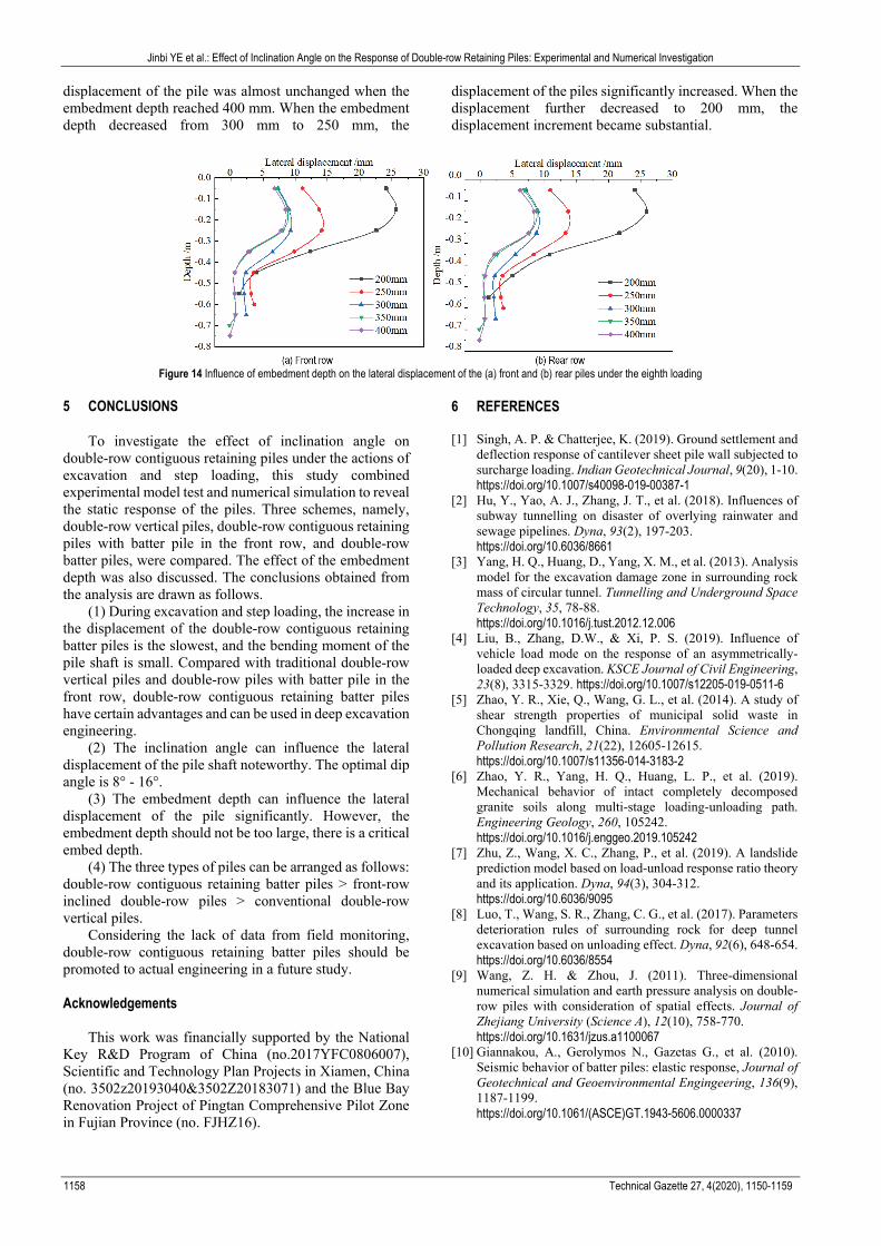
4.4 Effect of Embedment Depth
To investigate the effect of embedment depth, five numerical double-row inclined piles with different embedment depths (200, 250, 300, 350, and 400 mm) are simulated. The inclination angle and the load are 8° and 1.6 kN, respectively.
The lateral displacements of the front and rear rows of the piles at different embedment depths are displayed in Fig. 14. The embedment depth in the benchmark model is 300 mm. When the embedment depth increased from 300 mm to 350 mm, the maximum displacement of the front and back rows of piles mildly decreased but the displacement distribution changed. The lateral
Jinbi YE et al.: Effect of Inclination Angle on the Response of Double-row Retaining Piles: Experimental and Numerical Investigation
1158 Technical Gazette 27, 4(2020), 1150-1159
displacement of the pile was almost unchanged when the embedment depth reached 400 mm. When the embedment depth decreased from 300 mm to 250 mm, the
displacement of the piles significantly increased. When the displacement further decreased to 200 mm, the displacement increment became substantial.
Figure 14 Influence of embedment depth on the lateral displacement of the (a) front and (b) rear piles under the eighth loading
5 CONCLUSIONS
To investigate the effect of inclination angle on double-row contiguous retaining piles under the actions of excavation and step loading, this study combined experimental model test and numerical simulation to reveal the static response of the piles. Three schemes, namely, double-row vertical piles, double-row contiguous retaining piles with batter pile in the front row, and double-row batter piles, were compared. The effect of the embedment depth was also discussed. The conclusions obtained from the analysis are drawn as follows.
(1) During excavation and step loading, the increase inthe displacement of the double-row contiguous retaining batter piles is the slowest, and the bending moment of the pile shaft is small. Compared with traditional double-row vertical piles and double-row piles with batter pile in the front row, double-row contiguous retaining batter piles have certain advantages and can be used in deep excavation engineering.
(2) The inclination angle can influence the lateraldisplacement of the pile shaft noteworthy. The optimal dip angle is 8° - 16°.
(3) The embedment depth can influence the lateraldisplacement of the pile significantly. However, the embedment depth should not be too large, there is a critical embed depth.
(4) The three types of piles can be arranged as follows:double-row contiguous retaining batter piles > front-row inclined double-row piles > conventional double-row vertical piles.
Considering the lack of data from field monitoring, double-row contiguous retaining batter piles should be promoted to actual engineering in a future study.
Acknowledgements
This work was financially supported by the National Key R&D Program of China (no.2017YFC0806007), Scientific and Technology Plan Projects in Xiamen, China (no. 3502z20193040&3502Z20183071) and the Blue Bay Renovation Project of Pingtan Comprehensive Pilot Zone in Fujian Province (no. FJHZ16).
6 REFERENCES
[1] Singh, A. P. & Chatterjee, K. (2019). Ground settlement anddeflection response of cantilever sheet pile wall subjected tosurcharge loading. Indian Geotechnical Journal, 9(20), 1-10.https://doi.org/10.1007/s40098-019-00387-1
[2] Hu, Y., Yao, A. J., Zhang, J. T., et al. (2018). Influences ofsubway tunnelling on disaster of overlying rainwater andsewage pipelines. Dyna, 93(2), 197-203.https://doi.org/10.6036/8661
[3] Yang, H. Q., Huang, D., Yang, X. M., et al. (2013). Analysismodel for the excavation damage zone in surrounding rockmass of circular tunnel. Tunnelling and Underground SpaceTechnology, 35, 78-88.https://doi.org/10.1016/j.tust.2012.12.006
[4] Liu, B., Zhang, D.W., & Xi, P. S. (2019). Influence ofvehicle load mode on the response of an asymmetrically-loaded deep excavation. KSCE Journal of Civil Engineering,23(8), 3315-3329. https://doi.org/10.1007/s12205-019-0511-6
[5] Zhao, Y. R., Xie, Q., Wang, G. L., et al. (2014). A study ofshear strength properties of municipal solid waste inChongqing landfill, China. Environmental Science andPollution Research, 21(22), 12605-12615.https://doi.org/10.1007/s11356-014-3183-2
[6] Zhao, Y. R., Yang, H. Q., Huang, L. P., et al. (2019).Mechanical behavior of intact completely decomposedgranite soils along multi-stage loading-unloading path.Engineering Geology, 260, 105242.https://doi.org/10.1016/j.enggeo.2019.105242
[7] Zhu, Z., Wang, X. C., Zhang, P., et al. (2019). A landslideprediction model based on load-unload response ratio theoryand its application. Dyna, 94(3), 304-312.https://doi.org/10.6036/9095
[8] Luo, T., Wang, S. R., Zhang, C. G., et al. (2017). Parametersdeterioration rules of surrounding rock for deep tunnelexcavation based on unloading effect. Dyna, 92(6), 648-654.https://doi.org/10.6036/8554
[9] Wang, Z. H. & Zhou, J. (2011). Three-dimensionalnumerical simulation and earth pressure analysis on double-row piles with consideration of spatial effects. Journal ofZhejiang University (Science A), 12(10), 758-770.https://doi.org/10.1631/jzus.a1100067
[10] Giannakou, A., Gerolymos N., Gazetas G., et al. (2010).Seismic behavior of batter piles: elastic response, Journal ofGeotechnical and Geoenvironmental Engingeering, 136(9),1187-1199.https://doi.org/10.1061/(ASCE)GT.1943-5606.0000337

Jinbi YE et al.: Effect of Inclination Angle on the Response of Double-row Retaining Piles: Experimental and Numerical Investigation
Tehnički vjesnik 27, 4(2020), 1150-1159 1159
[11] Seo, M. S., Im J. C., Kim, C., et al.(2016). A study on theapplicability of retaining wall using batter piles in clay.Canadian Geotechnical Journal, 53, 1195-1212.https://doi.org/10.1139/cgj-2014-0264
[12] Wang, E. Y., Zhou, H. Z., Zheng, G., et al.(2019). Numericalanalyses of deformation of inclined pile-retainedexcavations. Chinese Journal of Geotechnical Engineering,41(sup. 1), 73-76.
[13] Cao, J., Qian, G.W., Yang, Z. S., et al. (2018). Study oncalculation model of double-row retaining wall based onequivalent truss model. Journal of Disaster Prevention andMitigation Engineering, 38(6), 943-949.
[14] Peng, W. X. & Liu, B. (2018). Indoor model test study onrow spacing of double-row piles supporting deep excavationpit. Journal of Hunan University (Natural Sciences), 45(1),121-127.
[15] Fall, M., Gao, Z.G., & Ndiaye, B.C. (2019). Subway tunnelsdisplacement analysis due to two different communicationchannels construction procedures. Heliyon, 5(6), e01949https://doi.org/10.1016/j.heliyon.2019.e01949
[16] Nisha, J.J., Muttharam, M., Vinoth, M. et al. (2019). Design,Construction and uncertainties of a deep excavation adjacentto the high-rise building. Indian Geotechnical Journal,49(5), 580-594. https://doi.org/10.1007/s40098-019-00368-4
[17] Soomro, M. I., Mangnejo, D. A., & Bhanbhro, R. (2019). 3D finite element analysis of pile responses to adjacentexcavation in soft clay: Effects of different excavationdepths systems relative to a floating pile. Tunnelling andUnderground Space Technology, 86, 138-155.https://doi.org/10.1016/j.tust.2019.01.012
[18] Shakee, M. & Ng, C.W.W. (2018). Settlement and loadtransfer mechanism of a pile group adjacent to a deepexcavation in soft clay. Computers and Geotechnics, 96, 55-72. https://doi.org/10.1016/j.compgeo.2017.10.010
[19] Goit, C.S. & Saitoh, M. (2019). Model tests and numericalanalyses on horizontal impedance functions of inclinedsingle piles. Earthquake Engineering and EngineeringVibration, 12,143-154.https://doi.org/10.1007/s11803-013-0158-0
[20] Jeyapriya, S. P. & Praveen, K.S. (2018). Behaviouralanalysis of vertical and batter pile groups under vertical andlateral loading in sand. Arabian Journal of Geosciences,11(706), 1-7. https://doi.org/10.1007/s12517-018-4032-2
[21] Pankaj, B., Laxmikant, Y., & Sandeep, K. C. (2019).Behavior of vertical and batter piles under lateral, uplift andcombined loads in non-cohesive soil. InnovativeInfrastructure Solutions, 4(55), 1-17.https://doi.org/10.1007/s41062-019-0242-z
[22] Ghazavi, M., Ravanshenas, P., & Lavasan, A. A. (2014).Analytical and numerical solution for interaction betweenbatter pile group. KSCE Journal of Civil Engineering, 18(7),2051-2063. https://doi.org/10.1007/s12205-014-0082-5
[23] Ghasemzadeh, H., Tarzaban, M., & Hajitaheriha, M.M.(2018). Numerical analysis of pile–soil–pile Interaction inpile groups with batter piles. Geotechnical and GeologicalEngineering, 36, 2189-2215.https://doi.org/10.1007/s10706-018-0456-4
[24] Liu, X. R., Kou, M. M., Feng, H., et al. (2018). Experimentaland numerical studies on the deformation response andretaining mechanism of h-type anti-sliding piles in claylandslide. Environmental Earth Sciences, 77(5), 163-176.https://doi.org/10.1007/s12665-018-7360-3
[25] Shen, Y. J., Yu, Y., Ma, F., et al. (2017). Earth pressureevolution of the double-row long-short stabilizing pilesystem. Environmental Earth Sciences, 76(586).https://doi.org/10.1007/s12665-017-6907-z
[26] Singh, T., Pal, M., & Arora, V. K. (2017). Ultimate capacityof batteredpilegroupssubjected to obliquepulloutloads insand. International Journal of Geosynthetics and GroundEngineering, 3(28).https://doi:10.1007/s40891-017-0103-9
Contact information:
Jinbi YE, PhD, Lecturer, (Corresponding author) 1) School of Civil Engineering and Architecture, Xiamen University of Technology, 2) Engineering Research Center of Structure Crack Control for Major Project, Fujian Province University, Room 402, 6th Jinggong Yuan, No. 600 Ligong Road, Jimei District,Xiamen, 361024, Fujian Province, China E-mail: [email protected]
Chenfei WANG, PhD, Lecturer, 1) School of Civil Engineering and Architecture, Xiamen University of Technology, 2) Engineering Research Center of Structure Crack Control for Major Project, Fujian Province University, Room 201, 6th Jinggong Yuan, No. 600 Ligong Road, Jimei District, Xiamen, 361024, Fujian Province, China E-mail: [email protected]
Weipeng HUANG, Master, Senior Engineer, Xiamen Zhongjian Dongbei Design Institute Co., Ltd, No. 120 Changqing Beili, Siming District, Xiamen, 361012, Fujian Province, China E-mail: [email protected]
Jing ZHANG, PhD Candidate, Department of Civil Engineering, Ryerson University, M5B 2K3, ON, Toronto, Canada Email: [email protected]
Xianqi ZHOU, PhD, Associate Professor, 1) School of Civil Engineering and Architecture, Xiamen University of Technology, 2) Basic Construction Division, Xiamen University of Technology Room 403, 6th Jinggong Yuan, No. 600 Ligong Road, Jimei District,Xiamen, 361024, Fujian Province, China E-mail: [email protected]