effect of hydrodynamic thrust bearings on rotordynamics · 3 along the impeller back shroud and...
TRANSCRIPT

1
The 12th International Symposium on Transport Phenomena and Dynamics of Rotating Machinery
Honolulu, Hawaii, February 17-22, 2008 ISROMAC12-2008-20076
EFFECT OF HYDRODYNAMIC THRUST BEARINGS ON ROTORDYNAMICS
Joel V. Madison
Chief Executive Officer Ebara International Corporation
350 Salomon Circle, Reno, NV 89434 (775) 356-2796
[email protected] ABSTRACT In cryogenic pumps and turbine expanders, the submerged motor or generator is cooled and the bearings lubricated by a predetermined portion of the liquefied gas being pumped or expanded. The cryogenic liquid is routed through a thrust-balancing device to control axial loads on the bearings. The thrust-balancing device is essentially a self-adjusting hydrodynamic thrust bearing with a particular system of flow passages, chambers, labyrinth seals and a stationary thrust plate on the hub side of the impeller or runner. Depending on the tolerance range of the clearances between these passages, the pressure distribution across the thrust balancing device is in some cases not uniform and generates a small asymmetry in the pressure distribution across the thrust-balancing device. This small asymmetry in the pressure distribution is rotating synchronously with the rotor and causes a small bending force on the rotor shaft affecting the dynamic performance of the rotor. The paper presents a detailed analysis of the effect of asymmetric pressure distributions in hydrodynamic thrust bearings on the rotordynamic performance. It is shown, that small tolerances of the clearances have only a minimal effect on the rotordynamics, but with increasing tolerances a resonant effect is observed due to the synchronous rotational speed of the rotor and the asymmetric pressure distribution.
INTRODUCTION During the performance testing, an Ebara International Corporation (EIC) high-pressure LNG pump exhibited high vibration levels. After testing, the rotating assembly and clearances of the pump were examined. It was found that the thrust-balancing device was situated at an angle relative to the shaft. The thrust-balancing device discussed in this paper is unique to EIC and is called the Thrust Equalizing Mechanism (TEM). It was theorized that the angle between the TEM impeller and the shaft caused an asymmetric pressure distribution resulting in a bending force on the shaft. Calculations and an analysis were performed to asses whether this unbalanced pressure distribution may affect the rotordynamic performance of the pump. It was found that small moment magnitudes minimally affected the rotordynamic performance, but as the moment magnitudes increased a resonant effect was observed due to the asymmetric pressure distribution and synchronous rotational speed. Sebastian Berger et al (1998, 2001) have studied the nonlinear influence of the thrust bearing on the dynamic behavior of a flexible shaft. Their study considers a perfect thrust bearing and a defected thrust bearing. The coupling between the thrust bearings and the bending vibrations of the shaft is analyzed in their publications and their study is supported by non-linear simulations. In contrast, non-linear calculations, simulations, and results presented below are supported by performance test data. NOMENCLATURE t time in seconds M(t) Moment as a function of time
2
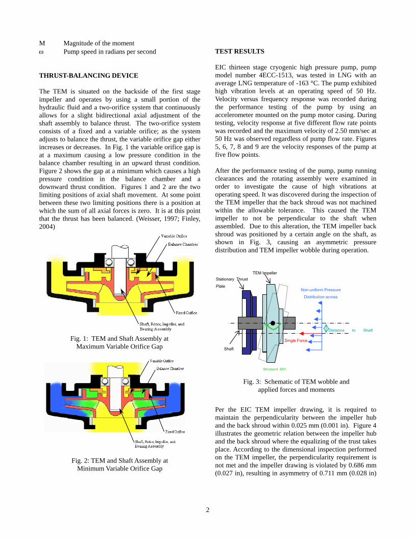
M Magnitude of the moment ω Pump speed in radians per second THRUST-BALANCING DEVICE The TEM is situated on the backside of the first stage impeller and operates by using a small portion of the hydraulic fluid and a two-orifice system that continuously allows for a slight bidirectional axial adjustment of the shaft assembly to balance thrust. The two-orifice system consists of a fixed and a variable orifice; as the system adjusts to balance the thrust, the variable orifice gap either increases or decreases. In Fig. 1 the variable orifice gap is at a maximum causing a low pressure condition in the balance chamber resulting in an upward thrust condition. Figure 2 shows the gap at a minimum which causes a high pressure condition in the balance chamber and a downward thrust condition. Figures 1 and 2 are the two limiting positions of axial shaft movement. At some point between these two limiting positions there is a position at which the sum of all axial forces is zero. It is at this point that the thrust has been balanced. (Weisser, 1997; Finley, 2004)
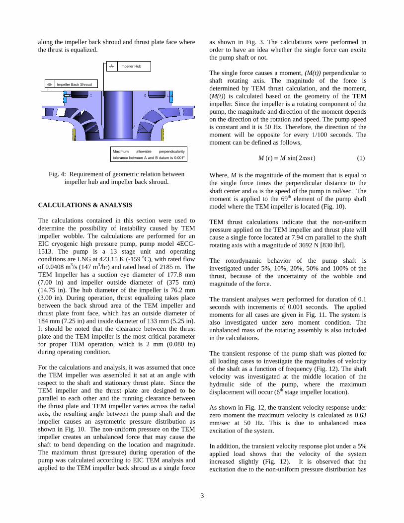
TEST RESULTS EIC thirteen stage cryogenic high pressure pump, pump model number 4ECC-1513, was tested in LNG with an average LNG temperature of -163 °C. The pump exhibited high vibration levels at an operating speed of 50 Hz. Velocity versus frequency response was recorded during the performance testing of the pump by using an accelerometer mounted on the pump motor casing. During testing, velocity response at five different flow rate points was recorded and the maximum velocity of 2.50 mm/sec at 50 Hz was observed regardless of pump flow rate. Figures 5, 6, 7, 8 and 9 are the velocity responses of the pump at five flow points. After the performance testing of the pump, pump running clearances and the rotating assembly were examined in order to investigate the cause of high vibrations at operating speed. It was discovered during the inspection of the TEM impeller that the back shroud was not machined within the allowable tolerance. This caused the TEM impeller to not be perpendicular to the shaft when assembled. Due to this alteration, the TEM impeller back shroud was positioned by a certain angle on the shaft, as shown in Fig. 3, causing an asymmetric pressure distribution and TEM impeller wobble during operation.
Per the EIC TEM impeller drawing, it is required to maintain the perpendicularity between the impeller hub and the back shroud within 0.025 mm (0.001 in). Figure 4 illustrates the geometric relation between the impeller hub and the back shroud where the equalizing of the trust takes place. According to the dimensional inspection performed on the TEM impeller, the perpendicularity requirement is not met and the impeller drawing is violated by 0.686 mm (0.027 in), resulting in asymmetry of 0.711 mm (0.028 in)
Fig. 1: TEM and Shaft Assembly at Maximum Variable Orifice Gap
Fig. 2: TEM and Shaft Assembly at Minimum Variable Orifice Gap
Single Force
Non-uniform Pressure Distribution across
Distance to Shaft
Moment M(t)
Shaft
Stationary Thrust Plate
TEM Impeller
Fig. 3: Schematic of TEM wobble and applied forces and moments
3
along the impeller back shroud and thrust plate face where the thrust is equalized.
Fig. 4: Requirement of geometric relation between impeller hub and impeller back shroud.
CALCULATIONS & ANALYSIS The calculations contained in this section were used to determine the possibility of instability caused by TEM impeller wobble. The calculations are performed for an EIC cryogenic high pressure pump, pump model 4ECC-1513. The pump is a 13 stage unit and operating conditions are LNG at 423.15 K (-159 oC), with rated flow of 0.0408 m3/s (147 m3/hr) and rated head of 2185 m. The TEM Impeller has a suction eye diameter of 177.8 mm (7.00 in) and impeller outside diameter of (375 mm) (14.75 in). The hub diameter of the impeller is 76.2 mm (3.00 in). During operation, thrust equalizing takes place between the back shroud area of the TEM impeller and thrust plate front face, which has an outside diameter of 184 mm (7.25 in) and inside diameter of 133 mm (5.25 in). It should be noted that the clearance between the thrust plate and the TEM impeller is the most critical parameter for proper TEM operation, which is 2 mm (0.080 in) during operating condition. For the calculations and analysis, it was assumed that once the TEM impeller was assembled it sat at an angle with respect to the shaft and stationary thrust plate. Since the TEM impeller and the thrust plate are designed to be parallel to each other and the running clearance between the thrust plate and TEM impeller varies across the radial axis, the resulting angle between the pump shaft and the impeller causes an asymmetric pressure distribution as shown in Fig. 10. The non-uniform pressure on the TEM impeller creates an unbalanced force that may cause the shaft to bend depending on the location and magnitude. The maximum thrust (pressure) during operation of the pump was calculated according to EIC TEM analysis and applied to the TEM impeller back shroud as a single force
as shown in Fig. 3. The calculations were performed in order to have an idea whether the single force can excite the pump shaft or not. The single force causes a moment, (M(t)) perpendicular to shaft rotating axis. The magnitude of the force is determined by TEM thrust calculation, and the moment, (M(t)) is calculated based on the geometry of the TEM impeller. Since the impeller is a rotating component of the pump, the magnitude and direction of the moment depends on the direction of the rotation and speed. The pump speed is constant and it is 50 Hz. Therefore, the direction of the moment will be opposite for every 1/100 seconds. The moment can be defined as follows,
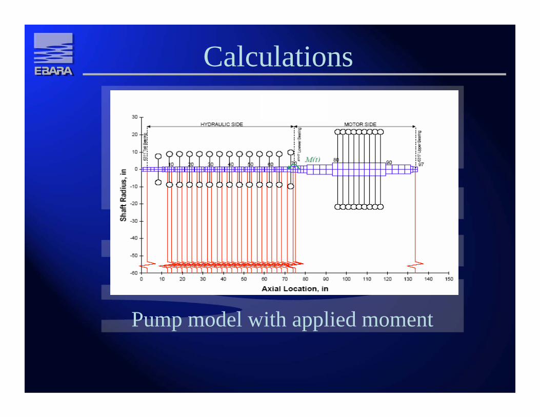
)2sin()( tMtM πω= (1) Where, M is the magnitude of the moment that is equal to the single force times the perpendicular distance to the shaft center and ω is the speed of the pump in rad/sec. The moment is applied to the 69th element of the pump shaft model where the TEM impeller is located (Fig. 10). TEM thrust calculations indicate that the non-uniform pressure applied on the TEM impeller and thrust plate will cause a single force located at 7.94 cm parallel to the shaft rotating axis with a magnitude of 3692 N [830 lbf]. The rotordynamic behavior of the pump shaft is investigated under 5%, 10%, 20%, 50% and 100% of the thrust, because of the uncertainty of the wobble and magnitude of the force. The transient analyses were performed for duration of 0.1 seconds with increments of 0.001 seconds. The applied moments for all cases are given in Fig. 11. The system is also investigated under zero moment condition. The unbalanced mass of the rotating assembly is also included in the calculations. The transient response of the pump shaft was plotted for all loading cases to investigate the magnitudes of velocity of the shaft as a function of frequency (Fig. 12). The shaft velocity was investigated at the middle location of the hydraulic side of the pump, where the maximum displacement will occur (6th stage impeller location). As shown in Fig. 12, the transient velocity response under zero moment the maximum velocity is calculated as 0.63 mm/sec at 50 Hz. This is due to unbalanced mass excitation of the system. In addition, the transient velocity response plot under a 5% applied load shows that the velocity of the system increased slightly (Fig. 12). It is observed that the excitation due to the non-uniform pressure distribution has
-A-
-B-
Maximum allowable perpendicularity tolerance between A and B datum is 0.001"
Impeller Hub
Impeller Back Shroud

4
no effect over the unbalanced mass excitation of the rotating assembly. Furthermore, similar behavior was also observed for a 10% applied moment (Fig. 12). There is a slight increase in velocity when 10% of the moment is applied to the system. The velocity response plot for a 20% applied moment indicates that the pump shaft becomes unstable by the application of this moment (Fig. 12). The velocity at operating speed increased by 17% compared to the no moment case. The maximum calculated velocity under this condition is 0.82 mm/sec. According to Fig. 12, when applying 50% of the moment at the TEM impeller location, the transient velocity response of the system increased by two times when compared to the no moment case. The system has instability at an operating speed of 50 Hz and the vibration level of the equipment is significantly increased by the moment as a result of the asymmetric pressure distribution. Based on results shown in Fig. 12, applying 100% of the moment will increase the velocity of the system by almost 4 times compared to zero the moment case. The maximum velocity is calculated as 2.4 mm/sec at the operating speed of 50 Hz. CONCLUSIONS The rotordynamic response analysis indicates that a small magnitude of moment due to asymmetric clearances between TEM impeller and stationary thrust plate have only a minimal effect on the rotordynamics, but with an increase the magnitude of the loading, a resonant effect is observed due to the synchronous rotational speed of the rotor and the asymmetric pressure distribution. Test results and dimensional inspection of the equipment prove that the non-uniform pressure distribution across the TEM impeller and stationary thrust plate can result in instability of rotating equipment during operation. REFERENCES Berger, s., Bonneau, O., Frene, J. “Influence of Axial Thrust Bearing Defects on the Dynamic Behavior of an Elastic Shaft.” AUSTRIB ’98, Tirbology Conference: Proceedings of the 5th International Tribology Conference in Australia, Brisbane 6-9 December 1998. Berger, s., Bonneau, O., Frene, J. “Influence of Axial Thrust Bearing on the Dynamic Behavior of an Elastic Shaft: Coupling Between the Axial Dynamic Behavior and the Bending Vibrations of a Flexible Shaft.” Journal of
Vibration and Acoustics, Vol. 123, Issue 2. April 2001. pp 145-149. Finley, C. “Continuously transient operation of two-phase LNG expanders.” AIChE Spring National Meeting, LNG IV. April 25-29, 2004. Weisser, L. “Hydraulic turbine power generator incorporating axial thrust equalizing means.” US Patent No. 5,659,205. 1997.

Fig. 5: Velocity response at 99.98 m3/s flow
5

Fig. 6: Velocity response at 126.76 m3/s flow
6
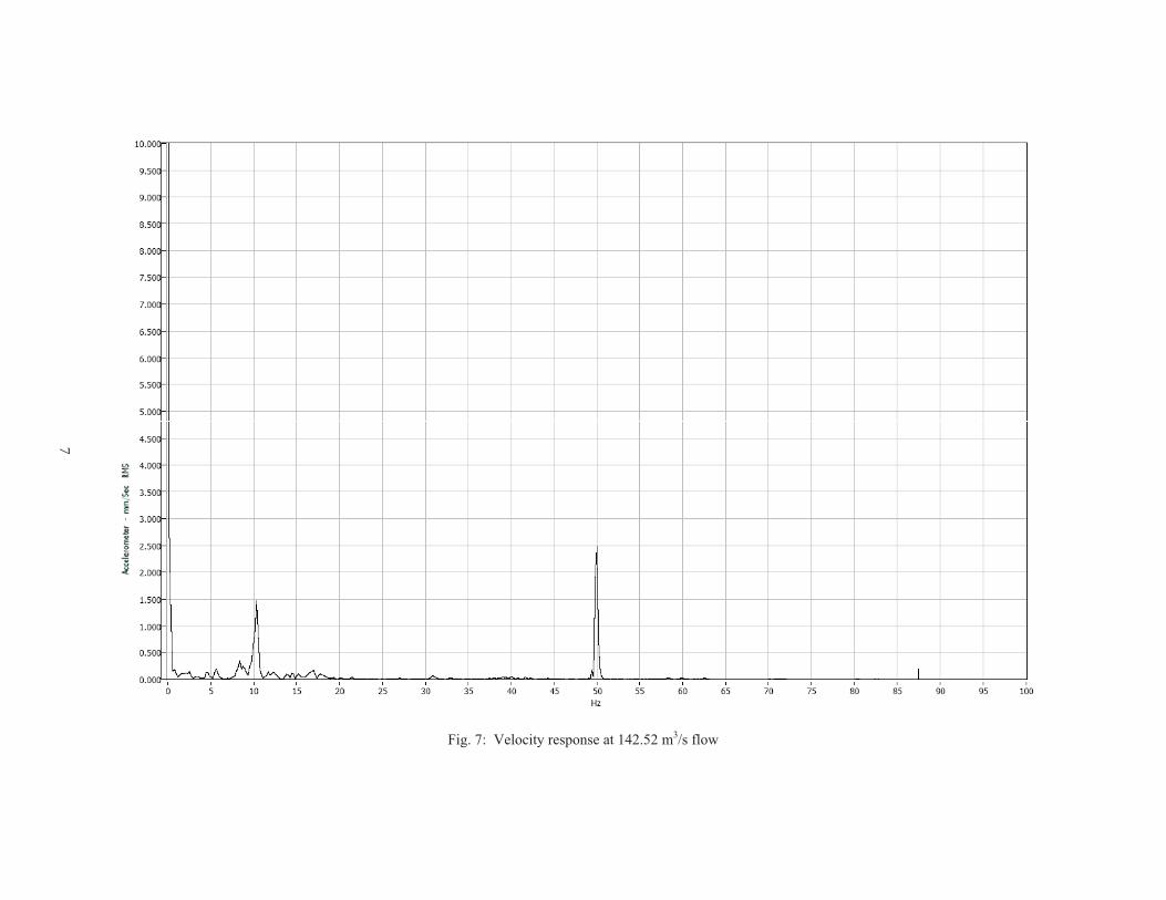
Fig. 7: Velocity response at 142.52 m3/s flow
7

Fig. 8: Velocity response at 178.20 m3/s flow
8

9
Fig. 9: Velocity response at 203.62 m3/s flow
Fig. 10: Pump shaft model with applied moment

10
Applied Moment at Station # 69 of Shaft Model
-400.00
-300.00
-200.00
-100.00
0.00
100.00
200.00
300.00
400.00
0 0.01 0.02 0.03 0.04 0.05 0.06 0.07 0.08 0.09 0.1
Time [sec]
Mom
ent [
N.m
]
M(t) 5% [N.m]M(t) 10% [N.m]M(t) 20% [N.m]M(t) 50% [N.m]M(t) 100% [N.m]
Fig. 11: Applied moment at station #69 as a function of time for six cases of applied moment
Velocity Transient Response
0
0.2
0.4
0.6
0.8
1
1.2
1.4
1.6
1.8
2
2.2
2.4
2.6
0 50 100 150 200 250 300 350 400 450 500
Frequency, Hz
Velo
city
, mm
/s
Applied Moment 100%
Applied Moment 50%
Applied Moment 20%
Applied Moment 10%
Applied Moment 5%
Applied Moment 0%
Fig. 12: Velocity transient response for six cases of applied moment

EFFECT OF HYDRODYNAMIC THRUST BEARINGS ON
ROTORDYNAMICSISROMAC 12
Honolulu, Hawaii February 19, 2008
Joel V. MadisonC.E.O.
Ebara International CorporationSparks, NV

Overview• Cause for investigation• Pump model• Thrust balancing device (TEM)• Performance testing results• Post-testing machine examination• TEM Wobble• Calculations• Results and analysis• Additional Analysis• Conclusions drawn• Questions

Cause for Investigation• During performance testing of an Ebara
International high pressure pump, the machine exhibited increased vibration levels at 50 Hz
• Examination of straightness and rotating balances checked and verified to be within design specification
• Concentricity of casing and close clearances checked and verified to be within design specification

• Large axial vibration at the operating speed led to examination of the Thrust Equalizing Mechanism (TEM) components
• Examination of the machine found the TEM impeller situated at an angle to the thrust plate
• Will the tilt of the TEM affect the rotordynamic performance?
Cause for Investigation

High Pressure Pump
• EIC model # 4ECC-1513• 13 stage high pressure
pump• Rated Flow: 147 m3/hr• Rated Head: 2185 m• Operating liquid: LNG• Operating temperature:
-159oC

Thrust Balancing Device (TEM)
TEM and shaft assembly at maximum variable orifice gap
TEM and shaft assembly at minimum
variable orifice gap

Performance Testing Results• High vibration levels at synchronous
speed of 50 Hz• Velocity vs. frequency response was
recorded during testing via accelerometer mounted on motor casing
• Radial velocity traces recorded at the middle bearing
• Velocity response recorded for 5 different flow rate points
• Maximum velocity of 2.5 mm/s at 50 Hz regardless of flow rate

Radial Velocity Response
Accelerometer vs. Frequency at a Flow Rate of 99.98 m3/s

Radial Velocity Response
Accelerometer vs. Frequency at a Flow Rate of 126.76 m3/s

Radial Velocity Response
Accelerometer vs. Frequency at a Flow Rate of 142.52 m3/s

Radial Velocity Response
Accelerometer vs. Frequency at a Flow Rate of 178.20 m3/s

Radial Velocity Response
Accelerometer vs. Frequency at a Flow Rate of 203.62 m3/s

• FFT recorded for the TEM probe• Found large synchronous vibration at operating
speed of 50 Hz
Axial Displacement

TEM Examination Findings• Running clearances and rotating
assembly was dismantled and examined
• During inspection of the TEM impeller it was found that the back shroud was not machined within tolerance
• TEM impeller back shroud was situated at an angle to the shaft

Required Geometric Relation• TEM impeller is required to maintain
perpendicularity between hub and back shroud within 0.025 mm
• Asymmetry of 0.711 mm found along impeller back shroud and thrust plate face

TEM Impeller WobbleAn angle between the TEM impeller and the shaft
causes an asymmetric pressure distribution resulting in TEM impeller wobble during operation.

CalculationsAssumptions:• TEM impeller was situated at an angle with
respect to shaft and stationary thrust plate• Running clearance varied across radial axis
between thrust plate and TEM impeller• Non-uniform pressure distribution resulted• Asymmetric pressure distribution can be
modeled as a single un-balanced force acting on the TEM impeller back shroud
• Un-balanced force causes a bending moment acting on the shaft

Calculations
• Thrust calculations indicate that the force is 3692 N and 7.94 cm from the rotating axis
• Since the impeller is a rotating component, the moment depends on the rotational direction and speed
• The pump speed is a constant 50 Hz : the direction of the moment will be opposite every 1/100 seconds
)2sin(*)( tMtM πω=
Calculations
Pump model with applied moment

Calculations• The rotordynamic behavior was investigated
under 5%, 10%, 20%, 50%, and 100% of the thrust
• Transient analyses were performed for a duration of 0.1s with increments of 0.001s
• The system was also investigated under zero moment condition
• Un-balanced mass was included• Transient response was plotted for all cases to
investigate the velocity as a function of frequency at the middle location of the hydraulic side of the pump where max displacement will occur

Applied moment as a function of time for all cases
Applied Moment ResultsApplied Moment at Station # 69 of Shaft Model
-400.00
-300.00
-200.00
-100.00
0.00
100.00
200.00
300.00
400.00
0 0.01 0.02 0.03 0.04 0.05 0.06 0.07 0.08 0.09 0.1
Time [sec]
Mom
ent [
N.m
]
M(t) 5% [N.m]M(t) 10% [N.m]M(t) 20% [N.m]M(t) 50% [N.m]M(t) 100% [N.m]

Transient Response: Zero MomentZero Applied Moment:• Max velocity 0.63 mm/s at 50 Hz• Due to un-balanced mass
Velocity Transient Response
0
0.1
0.2
0.3
0.4
0.5
0.6
0.7
0 100 200 300 400 500 600
Frequency, Hz
Velo
city
, mm
/s
[No Moment]

Transient Response: 5% & 10%
5% & 10% Applied Moment:
• Slight increase of system velocity
• Excitation due to non-uniform pressure has no effect over un-balanced excitation
Velocity Transient Response
0
0.1
0.2
0.3
0.4
0.5
0.6
0.7
0 100 200 300 400 500 600
Frequency, Hz
Velo
city
, mm
/s
Applied Moment: %5
Velocity Transient Response
0
0.1
0.2
0.3
0.4
0.5
0.6
0.7
0.8
0 100 200 300 400 500 600
Frequency, Hz
Velo
city
, mm
/s
Applied Moment: 10%

Transient Response: 20% Moment20% Applied Moment:• Max velocity 0.83 mm/s at 50 Hz• Primarily due to un-balanced mass
Velocity Transient Response
0
0.1
0.2
0.3
0.4
0.5
0.6
0.7
0.8
0.9
0 100 200 300 400 500 600
Frequency, Hz
Velo
city
,mm
/s
Applied Moment: 20%

Transient Response: 50% & 100%
50% Applied Moment• Velocity twice the zero
moment case• System unstable at 50 Hz• Vibration level of system
significantly increased by the moment
100% Applied Moment• Increase system velocity by
4 times the zero moment case
• Max velocity 2.4 mm/s at 50 Hz
Velocity Transient Response
0
0.2
0.4
0.6
0.8
1
1.2
1.4
1.6
0 100 200 300 400 500 600
Frequency, Hz
Velo
city
, mm
/s
Applied Moment: 50%
Velocity Transient Response
0
0.5
1
1.5
2
2.5
0 100 200 300 400 500 600
Frequency, Hz
Velo
city
, mm
/s
Applied Moment: 100%

Transient Response ResultsVelocity Transient Response
0
0.2
0.4
0.6
0.8
1
1.2
1.4
1.6
1.8
2
2.2
2.4
2.6
0 50 100 150 200 250 300 350 400 450 500
Frequency, Hz
Velo
city
, mm
/s
Applied Moment 100%
Applied Moment 50%
Applied Moment 20%
Applied Moment 10%
Applied Moment 5%
Applied Moment 0%
Transient response for all cases

Additional Analysis
Deflected shape of the shaft at operating speed
Shaft Deflected Shape at Operating Speed of 3000 RPM
0.000
0.025
0.050
0.075
0.100
0.125
0.150
0.175
0.200
0.225
0.250
0.275
0.300
0.325
0.350
0.375
0.400
0.425
0.450
0.475
0.500
0 10 20 30 40 50 60 70 80 90 100 110 120 130
Shaft Axial Location [in]
Dis
plac
emen
t [m
ils]
Applied Moment 0%Applied Moment 5%Applied Moment 10%Applied Moment 20%Applied Moment 50%Applied Moment 100%
Loca
tion
of th
e M
omen
t

Additional Analysis
Effect of moment on the critical speed
Rotordynamic Response Plot
0.00
0.50
1.00
1.50
2.00
2.50
3.00
3.50
4.00
4.50
5.00
5.50
6.00
6.50
7.00
7.50
0 1000 2000 3000 4000 5000 6000 7000 8000 9000
Rotor Speed [RPM]
Dis
plac
emen
t [m
ils]
Applied Moment 100%Applied Moment 50%Applied Moment 20%Applied Moment 10%Applied Moment 5%Applied Moment 0%

Conclusions• A small magnitude of moment due to
asymmetric clearances between the TEM impeller and thrust plate have a minimal effect on the rotordynamics
• Increased magnitude of moment results in a resonant effect due to synchronous rotational speed and asymmetric pressure distribution
• A non-uniform pressure distribution across the TEM impeller and asymmetric clearances may result in instability of rotating equipment during operation
• The critical speed is not affected by the moment