effect of harmonic excitation sequences on structures
TRANSCRIPT

Paper Number 37
Effect of harmonic excitation sequences on structures
2010 NZSEE
Conference
K. Twigden, X. Li, M. Ali, C. Oyarzo-Vera & N. Chouw
Department of Civil and Environmental Engineering, The University of Auckland, New Zealand.
ABSTRACT: It is common that aftershocks can still occur several months after a severe earthquake. Some of these aftershocks can have intensity high enough to increase the damage that is generated by a previous main shock or in some cases they can generate damage in a structure which was apparently intact after the main event. This situation is also applicable to the cumulative effect of all earthquakes that a structure experiences throughout its life time. This work analyses the response of structural members under a sequence of harmonic excitations, as a preliminary investigation. The results of this study will help in addressing the actual problem of earthquakes and aftershocks cumulative effects.
Coir fibre and rope reinforced concrete (CFRRC) columns were investigated under monotonic, cyclic and different harmonic loadings. Basic static properties of coir fibre reinforced concrete were also investigated using standard procedures. Load-displacement curves were obtained for monotonic and cyclic tests and the ductility of the specimen was calculated. Harmonic excitations were applied using a shake table. The change in dynamic properties of CFRRC columns was determined by an impact test after each ground motion excitation. A change in natural frequency is observed prior to the visible cracking of columns specimens. This shows that there is some non-visible material degradation in the specimen before cracking.
1 INTRODUCTION
Structures may experience a large number of earthquakes of different magnitudes during their life time. Properly designed structures behave well under medium intensity earthquakes. Apparently, no damage is usually observed as the structure remains within the elastic limit. However, the actual elastic limit of the structure cannot be defined exactly. When the structure goes near to or just exceeds its elastic limit during an earthquake, there may be some internal invisible damage. This can reduce its stiffness and, ultimately, its strength. Once the structure incurs in the non-linear range, further slight movement due to an earthquake aftershock can cause additional damage. Therefore, it is necessary to investigate the non-visible degradation of the structure during medium to high intensity earthquakes before any major collapse. If the time gap between two consecutive earthquakes is long enough, the non-visible degradation can be identified and appropriate remedial measures can be taken. Studies on the effect of earthquake of successive ground excitations are still very limited (Oyarzo-Vera and Chouw, 2008; Hatzigeorgiou and Beskos, 2009). In general they are based on numerical analysis, and no experimental research to address this subject has been found. Our work analyses experimentally the response of structural members under a sequence of harmonic excitations, as a preliminary approach to deal with the actual problem of cumulative structural degradation due to successive earthquake.
Coir fibre and rope reinforced concrete (CFRRC) columns were selected for this purpose. The reason for using this new material is to explore its behaviour as well. Coir fibres have the highest ductility among all natural fibres. Munawar et al. (2007) and Satyanarayana et al. (1990) reported strain of 24% and 39%, respectively, for coir fibres, whereas other natural fibres have strains in the range of 3-6%.
Shamim and Grace (2009) tested steel and fibre reinforced polymer (FRP) concrete columns under constant axial load and reversed cyclic lateral load that simulated forces from an earthquake. The main

2
variables investigated were axial load level, thickness and type of FRP. An increase in axial load re-sulted in reduced ductility and deformability of the column. The energy dissipation capacity of the sec-tion under lower axial load was more than 10 times that of the section under high axial load. The amount of FRP reinforcement needed to improve column behaviour depends on the level of axial load.
2 EXPERIMENTAL PROCEDURES
2.1 Specimens
A fibre length of 5 cm and a content of 3% were used for preparing coir fibre reinforced concrete (CFRC). The fibres preparation, casting CFRC and pouring of CFRC into moulds were performed as described by Ali and Chouw (2009), in which dynamic properties of coir fibre and rope reinforced concrete beams were determined experimentally. The basic static properties of CFRC were determined by standard procedures, normally used for plain concrete.
Figure 1 shows the cast-specimens from one concrete batch. The cylinders (100 mm diameter x 200 mm height) and beams (100 mm x 100 mm x 500 mm) were used to determine the basic static properties of CFRC. Column specimens having cross-section of 100 mm x 100 mm and height of 850 mm were casted along with base beams (100 mm x 100 mm x 600 mm). Coir ropes of 10 mm and 5 mm diameter were used as longitudinal and transverse reinforcement, respectively. The longitudinal reinforcement was used at corners and the transverse reinforcement was placed at 100 mm centres. The longitudinal reinforcement was pre-tensioned so that there should not be sagging while pouring the CFRC, and knots were provided near corners and at intersection of beam and column, to provide anchorage. A clear concrete cover of 15 mm was maintained with the help of removable steel rods (placed at 100 mm centres) as shown in Figure 2. These steel rods were removed after filling the mould with CFRC, and then the top surface was levelled.
Figure 1: Specimens Figure 2: Column specimen during CFRC pouring
2.2 Material properties
Table 1 summarises the material properties: compressive strength (σ), corresponding strain (ε), modulus of elasticity (E), splitting tensile strength (STS), modulus of rupture (MOR), and corresponding deflection (∆) and cracking load (PCrack), and maximum deflection (∆max). Cracking load is the load taken by fibres after the first visible crack is produced. All values are the average of three readings. It was observed that the cracks were produced in CFRC cylinders and spalling/splitting of plain concrete occured while performing compressive and tensile tests. CFRC small beams did not break into two pieces after crack is produced, ensuring the advantage of fibres. It may be noted that the maximum deflection (∆max) of beam is approximately 6.5 times the deflection at cracking (∆).

3
Table 1: Properties of coir fibre reinforced concrete
Cylinder testing Small beam testing Density (kg/m3) σ
(MPa) ε
(%) E
(GPa) STS
(MPa) MOR (MPa)
∆ (mm)
PCrack (kN)
∆max (mm)
40.8 0.17 31.8 3.95 5.01 1.8 2.6 11.6 2291
2.3 Testing
2.3.1 Specimen under monotonic loading
The set up for testing the column specimen under monotonic loading is shown in Figure 3a. The load was applied from one side at the top of column using a hydraulic actuator. The deflection was measured from the other side of column with a linear variable differential transformer (LVDT). The load applied to the column was measured by means of a load cell fixed between the column and the actuator. The maximum deflection of column after cracking is shown Figure 3b.
a. Test set up b. At maximum deflection
Figure 3: Monotonic loading test
2.3.2 Specimen under cyclic loading
Figure 4 shows the cyclic loading history used for testing column specimens. Two cycles of each displacement were applied to the top of column. The displacement increments were 1, 2, 4 and 8 mm up to the displacement of 6, 20, 32 and 72 mm, respectively. The test set up for column specimen under cyclic loading is shown in Figure 5a. LVDTs were fixed on both sides at the top of the column to measure displacements, and the load was measured using a load cell attached between column and actuator.
A crack was formed on the left side at bottom of column (Figure 5b) in the first cycle of 2 mm displacement during pulling (-ve displacement in loading history) and the column was deflected up to -6 mm. Then the column was pushed (+ve displacement in loading history) up to +2 mm, the crack on the other side was also formed. Further cycles of displacements were applied as per loading history. In the end of the test, four reversible cycles of 72 mm displacement were applied instead of two, because the column was still standing at its deflected position. The breaking of fibres could be easily heard without any device while applying the displacement of -14 mm and afterwards up to the displacement of 56 mm.
The maximum deflections of the column when pulling and pushing are shown in Figure 5b and 5c, respectively.

4
-72
-48
-24
0
24
48
72D
isp
lace
men
t (m
m)
6 mm20 mm
32 mm
72 mm
Figure 4: Cyclic loading history
a. Test set up b. Maximum deflection
when pulled c. Maximum deflection
when pushed
Figure 5: Cyclic loading test
2.3.3 Specimen under dynamic loading
The mounted column specimen on shake table is shown in Figure 6a. A mass of 105 kg was attached at the top of the column; this mass represents the equivalent mass of the considered structure. An accelerometer was attached at the top of column to measure response time-histories. An accelerometer was also attached at the base beam. The accelerometer readings of base beam and shake table coincided well, confirming that the specimen had a fixed support during testing.
The initial plan of these tests was to consider real earthquake records as base excitation. In fact, the El Centro record was used several times to produce damage in the column without any success. No visible damage was observed; even though the El Centro record was scaled up to the maximum capacity of the shake table and the mass at top was increased up to 165 kg. This situation can be explained by the difference between the natural frequency of specimen (between 15 to 20 Hz depending upon the attached mass) and the dominant frequency content of the earthquake (under 10 Hz) that does not allow dynamic amplifications. For this preliminary study, formal scaling procedures were not applied. After having experience about the behaviour of this novel material, the earthquake records will be scaled according to the scale of the structure.
Finally, two artificial excitations that match the natural frequency of the structure were employed: excitation series with increasing amplitude and sequence of main and secondary excitations, which may be regarded as a sequence of earthquakes without and with aftershocks, respectively. This
Pull Push

5
excitation pattern has a frequency content that passes through the fundamental frequency of the structure quickly, instead of matching system frequency. The purpose of this is to have controlled progressive damage instead of collapse because of resonance.
a. Excitation series with increasing amplitude
The excitation pattern applied by the shake table is shown in Figure 7. This pattern was applied until the specimen failure. The frequency of each acceleration series changes from 10 to 20 Hz in a period of 60 seconds. Modal testing was performed with the help of calibrated hammer. A small impact load was applied three times at mid height before applying the next acceleration series to the specimen. Note that the impact load is applied three times to take the average of resulting three values of a particular dynamic property. The columns failed at an acceleration of 0.25g. Figure 6b shows the specimen during cracking.
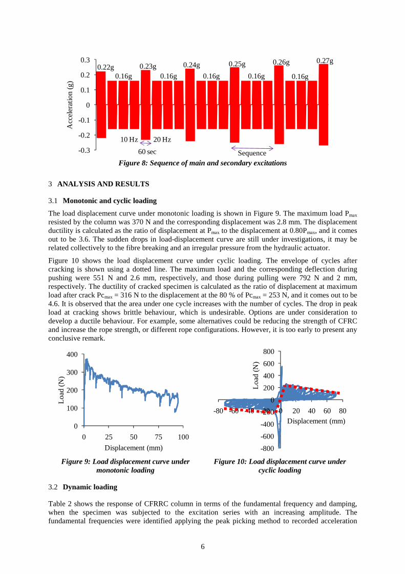
b. Sequence of main and secondary excitations
Another specimen was tested under a sequence of main and secondary excitations pattern (Figure 8). Each sequence consists in a “main excitation series” followed by three “secondary excitation series”, representing the main shock and subsequent aftershocks of an earthquake. The main excitation series have amplitudes ranging from 0.22g to 0.27g (increasing 0.01g in each successive sequence), while the secondary excitation series have a constant amplitude equals to 0.16g. The load pattern was applied until the specimen failure. The specimen failed at an acceleration of 0.27g. Modal testing was also performed after each excitation series. Each maximum acceleration amplitude was applied with changing frequency from 10 Hz to 20 Hz for a period of 60 seconds (Figure 7 and 8).
a. Specimen on shake table b. Specimen during cracking
Figure 6: Seismic loading test
-0.3
-0.2
-0.1
0
0.1
0.2
0.3
Acc
eler
atio
n (g
)
0.07g0.13g
0.17g 0.20g0.22g 0.23g 0.25g
60 sec
10
Hz
20 H
z
Figure 7: Excitation series with increasing amplitude
6
-0.3
-0.2
-0.1
0
0.1
0.2
0.3A
ccel
erat
ion
(g)
0.22g 0.23g 0.24g
0.16g 0.16g 0.16g
0.25g 0.27g
0.16g 0.16g
0.26g
60 sec
10 Hz 20 Hz
Sequence Figure 8: Sequence of main and secondary excitations
3 ANALYSIS AND RESULTS
3.1 Monotonic and cyclic loading
The load displacement curve under monotonic loading is shown in Figure 9. The maximum load Pmax resisted by the column was 370 N and the corresponding displacement was 2.8 mm. The displacement ductility is calculated as the ratio of displacement at Pmax to the displacement at 0.80Pmax, and it comes out to be 3.6. The sudden drops in load-displacement curve are still under investigations, it may be related collectively to the fibre breaking and an irregular pressure from the hydraulic actuator.
Figure 10 shows the load displacement curve under cyclic loading. The envelope of cycles after cracking is shown using a dotted line. The maximum load and the corresponding deflection during pushing were 551 N and 2.6 mm, respectively, and those during pulling were 792 N and 2 mm, respectively. The ductility of cracked specimen is calculated as the ratio of displacement at maximum load after crack Pcmax = 316 N to the displacement at the 80 % of Pcmax = 253 N, and it comes out to be 4.6. It is observed that the area under one cycle increases with the number of cycles. The drop in peak load at cracking shows brittle behaviour, which is undesirable. Options are under consideration to develop a ductile behaviour. For example, some alternatives could be reducing the strength of CFRC and increase the rope strength, or different rope configurations. However, it is too early to present any conclusive remark.
0
100
200
300
400
0 25 50 75 100
Loa
d (N
)
Displacement (mm) -800
-600
-400
-200
0
200
400
600
800
-80 -60 -40 -20 0 20 40 60 80
Lo
ad (N
)
Displacement (mm)
Figure 9: Load displacement curve under monotonic loading
Figure 10: Load displacement curve under cyclic loading
3.2 Dynamic loading
Table 2 shows the response of CFRRC column in terms of the fundamental frequency and damping, when the specimen was subjected to the excitation series with an increasing amplitude. The fundamental frequencies were identified applying the peak picking method to recorded acceleration

7
frequency response functions (FRF). The logarithmic decrement method was used to measure the damping of the specimens. There is a systematic frequency decrement, but that is not very significant (Figure 11). It indicates that there is some non-visible material degradation even after very small magnitude acceleration.
Table 2: Results of excitation series with increasing amplitude test
Acceleration applied Column response
Fundamental frequency (Hz)
Damping ratio (%)
0.00g 14.04 2.22
0.07g 13.88 2.60
0.13g 13.88 2.15
0.17g 13.73 2.56
0.20g 13.79 2.62
0.22g 13.63 2.51
0.23g 13.63 2.75
0.25g Specimen collapsed.
Table 3: Results of sequence of main and secondary excitations test
Sequence Acceleration applied Column response
Fundamental frequency (Hz)
Damping ratio (%)
0 0g 13.71 1.17
1 0.22g, 0.16g, 0.16g, 0.16g 13.16, 12.82, 12.70, 12.70 2.24, 2.87, 1.90, 1.51
2 0.23g, 0.16g, 0.16g, 0.16g 12.53, 12.45, 12.37, 12.25 1.40, 2.31, 1.55, 1.69
3 0.24g, 0.16g, 0.16g, 0.16g 12.33, 12.16, 12.33, 12.25 1.83, 1.81, 1.80, 2.02
4 0.25g, 0.16g, 0.16g, 0.16g 11.84, 11.56, 11.51, 11.76 3.94, 3.65, 2.51, 2.16
5 0.26g, 0.16g, 0.16g, 0.16g 11.15, 10.80, 10.76, 10.87 3.65, 3.76, 4.10, 3.66
6 0.27g Specimen broken
13.50
13.75
14.00
14.25
0 0.07 0.13 0.17 0.20 0.22 0.23Fu
nd
am
ent
al f
requ
enc
y (H
z)
Acceleration (g)
11
12
13
14
0 0.22 0.23 0.24 0.25 0.26
Fu
nd
am
ent
al f
requ
enc
y (H
z)
Acceleration (g)
Figure 11: Frequency decrement for excitation series with increasing amplitude
Figure 12: Frequency decrement for sequence of main and secondary excitations

8
The fundamental frequency and damping of CFRRC column, when specimen is subjected to sequence of main and secondary excitations is presented in Table 3. It can be observed that the fundamental frequency generally decreases after each main excitation series of 0.22g, 0.23g, 0.24g, 0.25 and 0.26g (Figure 12), and a less significant frequency degradation is also detected after the secondary excitation series
4 CONCLUSIONS
This work presented the results of preliminary investigations on the behaviour of coir fibre and rope reinforced concrete (CFRRC) columns under different loading sequences. The basic properties of CFRC were also determined. During the modulus of rupture test, it was observed that the beam reached a maximum deflection of approximately 6.5 times the deflection at first cracking, and the specimen was still held together by the fibres. The displacement ductility of CFRRC columns under monotonic and cyclic loading were 3.6 and 4.6, respectively.
The results of both dynamic tests reveal that non-visible degradation occurred prior to the cracking of column by the decrement of natural frequency. This frequency change is detected even in the case of small magnitude excitations (secondary excitation series) applied after a significant magnitude excitation (main excitation series). Similarly, it is expected that the natural frequency degradation can also be identified in the case of real earthquakes followed by aftershocks. Consequently, appropriate remedial measures are possible during the time gap between two consecutive earthquakes.
Following are recommendations for future studies: • Investigations of CFRRC columns under real earthquake loading • Numerical simulation of damage progression on CFRRC structures • Behaviour of CFRC columns with different configuration of rope reinforcement
ACKNOWLEDGEMENTS
The authors would like to thank all persons who helped them throughout the research, particularly Mark Byrami, Noel Perinpanayagam, Sujith Padiyara, Teck Goon Ang, Quincy Ma, and Golden Bay Cement and Winstone Aggregates for their support of this research. Thanks also to anonymous reviewer for the suggestions and constructive comments.
REFERENCES:
Ali, M. and Chouw, N. 2009. Coir fibre and rope reinforced concrete beams under dynamic loading. Annual Aus-tralian Earthquake Engineering Society Conference, “Newcastle Earthquake – 20 years on”, Paper 04.
Hatzigeorgiou, G. D., and Beskos, D. E. (2009). "Inelastic displacement ratios for SDOF structures subjected to repeated earthquakes." Engineering Structures, 31(11):2744-2755.
Munawar, S. S., Umemura, K., and Kawai, S. 2007. Characterization of the morphological, physical, and mechanical properties of seven nonwood plant fiber bundles. Journal of Wood Science, 53(2): 108-113.
Oyarzo Vera, C., and Chouw, N. 2008. "Effect of earthquake duration and sequences of ground motions on structural responses." 10th International Symposium on Structural Engineering for Young Experts, Changsha, China.
Shamim A. S. and Grace Y. 2009. Seismic behaviour of concrete columns confined with steel and fibre-reinforced polymers. ACI Structural Journal, 99(1): 72-80.
Satyanarayana, K. G., Sukumaran, K., Mukherjee, P. S., Pavithran, C., and Pillai, S. G. K. 1990. Natural fibre-polymer composites. Cement and Concrete Composites, 12(2): 117-136.