effect of fiber surface treatment in carpet …effect of fiber surface treatment in carpet recycling...
TRANSCRIPT

EFFECT OF FIBER SURFACE TREATMENT IN CARPET
RECYCLING
By
ABHISHEK JAIN
Bachelor of Science in Mechanical EngineeringRajiv Gandhi Proudyogiki Vishwavidyalaya
Bhopal, MP, India2008
Submitted to the Faculty of theGraduate College of
Oklahoma State Universityin partial fulfillment of
the requirements forthe Degree of
MASTER OF SCIENCEJuly, 2010

COPYRIGHT c©
By
ABHISHEK JAIN
July, 2010

EFFECT OF FIBER SURFACE TREATMENT IN CARPET
RECYCLING
Thesis Approved:
Dr. Raman P. Singh
Thesis Advisor
Dr. Kaan A. Kalkan
Dr. Sandip Harimakar
Dr. Mark E. Payton
Dean of the Graduate College
iii

ACKNOWLEDGMENTS
I would like to express my gratitude and appreciation to the members of my thesis
committee, Dr. Sandip Harimkar and Dr. Kaan Kalkan for their valuable time and feedback.
I would like to thank my mentor Dr. Raman P. Singh for his guidance and support. I
have learnt a lot of things from him in just two years. The very friendly environment he
creates while working helps a lot in dealing with problems. He has totally changed my way
of looking at the problem. I would also like to thank Seshumani Vorrey for her help and
interest in this work.
I would like to thank my roommates Kunal Mishra (bihari, maalik, seth ji), Abhisek
Bhadra (a= alpha, b= banana...), and Suman Dasgupta (scored 13 goals in a very big soccer
tournament). Special thanks to Liela and Arif (alylhydro) for their help. I am grateful to all
my lab-mates including Chirag (chotu), Dhivakar (the man ??), Mohammed (mamagela),
Phil (gora desi), Austin (hain hain hain.....), Hamim (earphone man), Sadia, Chaitanya (ya
dude), Balaji (Sheldon Cooper), and Vasudevan (bhagvaan) for their help.
I have been really lucky to work with Dr. Abhishek K. Singh (hum batayein.....), and
unlucky also, for not getting enough time to learn more from him. Dr. Gajendra Pandey
(kcowboy) has been a great mentor through out my studies and my stay here in US.
Dr. Pranav Nawani has now become a new mentor, and i would also like to thank him.
At last but not the least, I would like to thank my father, mother, and my younger
brother, for their support,faith, and love. Hearty thanks to Sumedha for being my friend. I
am also grateful to Nikhil Jain (childhood buddy) for being my friend in all my good and
bad times. Sweta, Shubhi, Neha, Amit (pappu), Yogesh (seth jiii), Prasanna (anna), Amit
(compounder), and lot more many people, I am thankful to all.
iv

TABLE OF CONTENTS
Chapter Page
1 INTRODUCTION 1
1.1 PROBLEM STATEMENT . . . . . . . . . . . . . . . . . . . . . . . . . . 1
1.2 CARPET CONSTRUCTION . . . . . . . . . . . . . . . . . . . . . . . . . 2
1.3 CONVENTIONAL CARPET RECYCLING TECHNIQUES . . . . . . . . 4
1.3.1 Primary Recycling or Depolymerization . . . . . . . . . . . . . . . 5
1.3.2 Secondary Recycling by Polyamide Extraction . . . . . . . . . . . 8
1.3.3 Tertiary Recycling or Melt blending . . . . . . . . . . . . . . . . . 10
1.3.4 Quaternary Recycling or Incineration . . . . . . . . . . . . . . . . 11
1.4 NEED OF AN EASY RECYCLING PROCESS . . . . . . . . . . . . . . . 11
2 FABRICATION, CHARACTERIZATION AND ANALYSIS 13
2.1 FABRICATION OF CARPET LAMINATES . . . . . . . . . . . . . . . . 13
2.2 MATERIAL CHARACTERIZATION . . . . . . . . . . . . . . . . . . . . 15
2.2.1 Optical Inspection . . . . . . . . . . . . . . . . . . . . . . . . . . 15
2.2.2 Density and Porosity Measurement . . . . . . . . . . . . . . . . . 17
2.2.3 Mechanical Characterization . . . . . . . . . . . . . . . . . . . . . 18
2.3 RESULTS AND DISCUSSION . . . . . . . . . . . . . . . . . . . . . . . 19
2.3.1 Density and Porosity . . . . . . . . . . . . . . . . . . . . . . . . . 19
2.3.2 Flexural properties . . . . . . . . . . . . . . . . . . . . . . . . . . 20
2.3.3 Failure Characterization . . . . . . . . . . . . . . . . . . . . . . . 23
2.3.4 Conclusions . . . . . . . . . . . . . . . . . . . . . . . . . . . . . . 24
v

3 SURFACE TREATMENT OF NYLON FACE FIBERS 26
3.1 NYLON FIBERS AND THEIR PROPERTIES . . . . . . . . . . . . . . . 26
3.2 WORK DONE ON MODIFYING SURFACE CHEMISTRY . . . . . . . . 27
3.3 DYES AND STAIN RESISTANT CHEMICALS IN CARPET . . . . . . . 30
3.4 INDUCTIVE COUPLED PLASMA ELEMENTAL ANALYSIS . . . . . . 32
3.5 FTIR OF PURE NYLON 6 AND NYLON 6,6 . . . . . . . . . . . . . . . . 34
3.6 EXPERIMENTATION . . . . . . . . . . . . . . . . . . . . . . . . . . . . 34
3.6.1 Surface treatment, Fabrication and Characterization . . . . . . . . . 34
3.7 RESULTS AND DISCUSSION . . . . . . . . . . . . . . . . . . . . . . . 36
3.7.1 pH Measurement . . . . . . . . . . . . . . . . . . . . . . . . . . . 36
3.7.2 FTIR Spectrometry . . . . . . . . . . . . . . . . . . . . . . . . . . 37
3.7.3 Surface Roughness . . . . . . . . . . . . . . . . . . . . . . . . . . 41
3.7.4 Density and Porosity of Fabricated Laminates . . . . . . . . . . . . 41
3.7.5 Flexural properties . . . . . . . . . . . . . . . . . . . . . . . . . . 43
3.7.6 Failure Characterization . . . . . . . . . . . . . . . . . . . . . . . 44
3.7.7 Possible Mechanism . . . . . . . . . . . . . . . . . . . . . . . . . 46
3.8 CONCLUSIONS . . . . . . . . . . . . . . . . . . . . . . . . . . . . . . . 49
4 CONCLUSIONS 52
BIBLIOGRAPHY 54
vi

LIST OF TABLES
Table Page
2.1 Specimen fabrication . . . . . . . . . . . . . . . . . . . . . . . . . . . . . 15
2.2 Density and porosity values of carpet composites fabricated using the VARTM
technique. . . . . . . . . . . . . . . . . . . . . . . . . . . . . . . . . . . . 20
2.3 Mechanical properties of the composite fabricated. . . . . . . . . . . . . . 21
3.1 ICP data showing the elements and their amount present in carpet. . . . . . 33
3.2 The pH values of the solvents before and after soaking. . . . . . . . . . . . 36
3.3 FTIR spectra assignment of untreated and treated carpet fibers (cm−1) . . . 38
3.4 Density an porosity values of carpet composites fabricated using the VARTM
technique after surface treatment. . . . . . . . . . . . . . . . . . . . . . . . 43
3.5 Mechanical properties of the composite panels. . . . . . . . . . . . . . . . 44
vii

LIST OF FIGURES
Figure Page
1.1 Tufting method to manufacture carpet pile, adapted from [1]. . . . . . . . . 3
1.2 Application of secondary backing, adapted from [1]. . . . . . . . . . . . . 4
1.3 Architecture of the two most common type of carpet used. . . . . . . . . . 4
2.1 Vacuum assisted resin transfer molding of carpet laminates . . . . . . . . . 14
2.2 Images of nylon based carpet composite panels prepared using VARTM
process. . . . . . . . . . . . . . . . . . . . . . . . . . . . . . . . . . . . . 16
2.3 Three point bend flexure test of the carpet composite. A nylon based com-
posite in FBBF configuration has been shown here at failure. . . . . . . . . 18
2.4 Load–displacement graphs for Nylon based carpet composite . . . . . . . . 21
2.5 Comparison of modulus of elasticity of composites fabricated by Mancosh
et al. [2] and the material fabricated under the current work. . . . . . . . . 23
2.6 Scanning electron micrograph of a fiber at the fractured surface of the com-
posite with vinyl ester as a matrix. . . . . . . . . . . . . . . . . . . . . . . 24
3.1 Intermolecular hydrogen bonding between two adjacent chains of Nylon 6,6. 27
3.2 Depolymerization of polyamide chain using acid and catalyst [3]. . . . . . . 30
3.3 Infrared spectra of Nylon 6 and Nylon 6,6 fibers. (A) nylon 6 ; (B) nylon
6,6 [4]. . . . . . . . . . . . . . . . . . . . . . . . . . . . . . . . . . . . . . 35
3.4 Superimposed IR spectra of virgin fibers against fibers treated with iso-
propanol, methanol, sodium hydroxide, and potassium hydroxide. . . . . . 37
3.5 FTIR spectra comparison of untreated and treated carpet fibers with MeOH. 38
3.6 Lewis acid-base complexation mechanism scheme. . . . . . . . . . . . . . 39
viii

3.7 FTIR spectra of the fibers treated with Isopropylalcohol . . . . . . . . . . . 39
3.8 FTIR spectra of fibers treated with sodium hydroxide. . . . . . . . . . . . . 40
3.9 FTIR spectra of fibers treated with potassium hydroxide. . . . . . . . . . . 41
3.10 Atomic force microscopy image comparison of the roughness of a virgin
fiber and a fiber treated with Methanol and sodium hydroxide (0.5 M). . . . 42
3.11 Stress-strain curves of the composites fabricated after surface treatment. . . 44
3.12 The crack developed in the composite samples when loaded to failure in a
three-point bend test. . . . . . . . . . . . . . . . . . . . . . . . . . . . . . 45
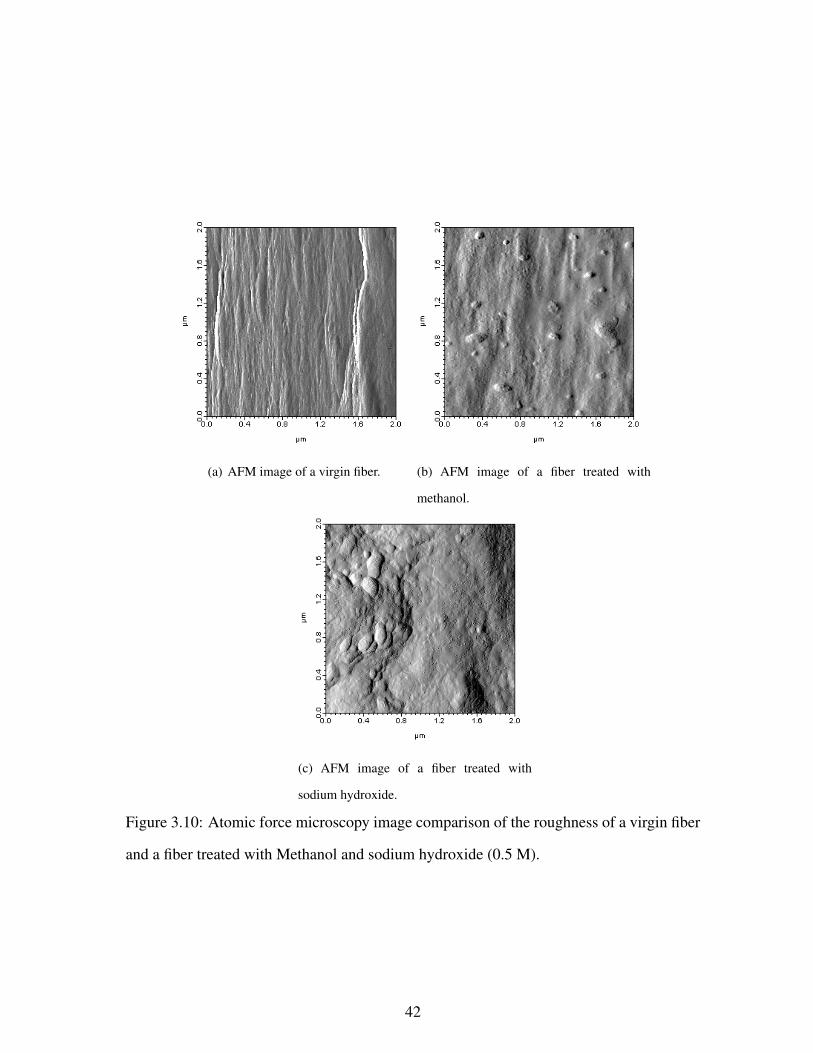
3.13 Scanning electron micrograph of the treated fibers composite at the frac-
tured surface. . . . . . . . . . . . . . . . . . . . . . . . . . . . . . . . . . 46
3.14 FTIR spectra comparison of untreated and treated fibers, when cured the
vinyl ester resin. . . . . . . . . . . . . . . . . . . . . . . . . . . . . . . . . 47
3.15 FTIR spectra comparison of vinyl ester resin used in current study and the
vinyl ester resin used by Rosu et al. [5] to confirm the structure of the resin. 48
3.16 Structure of the resin proposed by Rosu et al. [5], prepared by addition of
monocarboxilic acid and an epoxy backbone. . . . . . . . . . . . . . . . . 48
3.17 A proposed possible mechanism of interaction of vinyl ester resin with the
nylon 6,6 molecule treated with methanol. . . . . . . . . . . . . . . . . . . 49
3.18 Second proposed possible mechanism of interaction of vinyl ester resin
with the Nylon 6,6 molecule treated with methanol. . . . . . . . . . . . . . 50
3.19 Third proposed possible mechanism of interaction of vinyl ester resin with
the Nylon 6,6 molecule treated with methanol. . . . . . . . . . . . . . . . . 50
ix

CHAPTER 1
INTRODUCTION
1.1 PROBLEM STATEMENT
Carpet is extensively used as a floor covering in households and commercial buildings. It
is generally a pile of synthetic fibers tufted in a backing. Carpet is made to be very durable
and long lasting, but after a certain period of time it needs to be replaced, and old carpet
is disposed to landfills. In the United States, about 200 million metric tons (450 billion
pounds) of carpet waste is generated every year. Only 2%, around 4 million tons (8.8
billion pounds) of this, is recycled [6]. Nearly all the rest of the waste is disposed into the
landfills.
Post-consumer carpet accounts for approximately 1 wt.% and 2-vol.% of the municipal
solid-waste stream in the United States, and this number is increasing every year [7]. Since
the average life expectancy of a carpet is about 11 years [8], it has already become one of
the largest components of post-consumer solid waste going to landfill. In addition, carpet
is non-biodegradable, which diminishes the availability of landfills for other uses.
Apart from environmental problems, there are many economical aspects associated with
carpet waste. These involve direct and indirect costs for the disposal of carpet waste. The
direct cost includes the money given for discarding it to the landfill which is approximately
equal to $0.025/lb [9]. At present, carpet waste is discarded to landfills at a rate of $100
million per year in the United States. The indirect cost associated with the disposal of carpet
waste may include the discarding of valuable raw material in the form of high engineering
value fibers going to landfills. These fibers involve Nylon 6,6, polypropylene, polyester,
polyvinyl chloride etc.
1

Mainly two types of carpet waste is generated, which can be broadly classified on
their source of origin: pre-consumer carpet waste and post-consumer carpet waste. Pre-
consumer carpet waste includes scrap generated during the process of making carpets for
various consumer based applications, such as in automobiles, households or commercial
buildings. As an example, in the case of automobiles, a considerable amount of carpet
scrap is generated during the trimming and fitting process of cars. This scrap has a de-
formed and irregular shape and has no further use. Pre-consumer carpet waste accounts
for about 12% of the total carpet discarded [7]. On the other hand, post-consumer waste
includes used carpet generated due to exhaustion of its lifetime from the households and
commercial buildings. In addition, used carpet from specialized sources, such as aircrafts,
can contain chemical additives such as flame-retardents, stain resistant chemicals etc. This
type of carpet waste contains various impurities, which makes its reuse or recycling process
generally more complex.
Carpets are manufactured in various types and varieties, which are different from each
other. So it becomes important to study the variety and types of carpet manufactured–their
construction and how they are manufactured.
1.2 CARPET CONSTRUCTION
Broadly, carpet can be classified as per its construction and the face fiber materials used in
carpet. Based on the construction, carpet is classified as cut-pile, level-loop, and multilevel-
loop. Additionally, based on face fiber material, carpet is classified as Nylon 6, Nylon
6,6, polypropylene, olefin, polyester, and polyvinyl chloride. Generally, carpet consists of
face fibers, primary backing, secondary backing, adhesive, and filler materials. Primary
backing is the material into which yarn of face fibers is tufted. Secondary backing is the
material laminated to the back of the carpet pile. The backings could either be woven or
non–woven, and are generally made up of polypropylene or polyester. Tufting is the most
common method used for manufacturing carpet. Tufting is a process of forming a loop of
2

fiber yarn across a woven textile backing material as shown in Fig. 1.1. In this process, the
backing substrate is passed under a set of needles carrying fiber yarn. Then these needles
are inserted through the backing and drawn back. This process is repeated several times
to create a continuous loop of fibers tufted through the primary backing. This loop of
continuous fiber yarn can be cut or sheared to form a cut pile or it can be left as it is to form
a level-loop or multilevel-loop. Adhesive is used to bond secondary backing with primary
backing tufted with the fiber yarn. Filler material is mixed with adhesive to cover the entire
area of secondary backing. Figure 1.2 shows the application of secondary backing.
ch
Figure 1.1: Tufting method to manufacture carpet pile, adapted from [1].
The two most common types of carpet found in the US are cut-pile and level-loop as
shown in fig 1.3. Generally household cut-pile carpet consists of 50% by weight face fiber.
These are typically Nylon 6, or Nylon 6,6. The primary and secondary backing constitutes
10% of total carpet material, which is generally made up of polypropylene. Adhesive used
for the adhesion of face-fibers and backings is styrene-butadiene and constitutes 9% of total
carpet weight. Around 25–30 wt.% of the filler used in the carpet, is calcium carbonate. The
other mostly used type of carpet is level-loop type of carpet. It has generally olefin as face
fibers and polypropylene as the backing. It is also manufactured by using polypropylene as
3

Figure 1.2: Application of secondary backing, adapted from [1].
the face fibers and the backing.
This chemical and physical diversity in carpet makes it very difficult to recycle carpet
waste. Nonetheless, a lot of research work has been done to recycle carpet waste, which is
discussed in next section.
(a) Typical construction of cut-pile type of carpet.
(b) Typical construction of level-loop type of carpet.
Figure 1.3: Architecture of the two most common type of carpet used.
1.3 CONVENTIONAL CARPET RECYCLING TECHNIQUES
There has been a considerable interest in developing techniques to recycle carpet waste.
However, it is very challenging to recycle carpet because of its multicomponent structure
which is chemically diverse in nature. Several recycling approaches have been proposed
4

so far, which differ by the type of process used and consequently by type and quality of
the product generated. The recycling of carpet waste has been classified into four main
categories [10]:
Primary recycling or depolymerization: This involves converting the constituents of car-
pet into their monomers. It is a chemical process which breaks down the polymers
into monomers, which could again be polymerized.
Secondary recycling or polyamide extraction: This mainly includes the separation of
individual components without breaking them down into their monomers. It involves
separation of fibers and backing using shredders and choppers.
Tertiary recycling or melt-blending: This involves preparing a mixture of all the com-
ponents of carpet by melt blending. It does not involve separation of face fibers and
backing. The mixture thus obtained is used for making secondary low–cost plastic
materials.
Quaternary recycling or incineration: This includes the recovery of energy by simply
burning down the polymer waste in the kilns.
1.3.1 Primary Recycling or Depolymerization
Many researchers have studied this process in carpet recycling. It is a chemical process
which converts face fibers into their monomeric form. This approach involves separation
of the face fibers from backing and then chemically converting them into their monomers.
Mainly the depolymerization of Nylon 6 occurs in an initiation or de–propagation step [11].
Water is used as the initiator of the process. Since this is an endothermic reaction, it re-
quires high temperature, so superheated steam is used to provide high temperature. Water
or steam also acts as a reaction initiator. The temperature is kept around 267 ◦C, which is
the melting point for caprolactum. This process results in a heterogenous mixtures of poly-
mer waste and gaseous phase caprolactam. The gas is taken out from the reactor along with
5
the steam. The reaction takes place at low pressure because it is easy to separate monomers.
Sometimes catalysts such as Lewis acid, Brnsted acid and bases, are also added to acceler-
ate the reaction [11].
Various polymers, and precursor can be extracted from this polymer waste. Mckinney
et al. [12] have done recovery of hexamethylene diamine and adipic acid (monomers of
Nylon 6,6) from the mixture of polymers using ammonolysis. The process takes place in
the presence of ammonia at high temperature and pressure. One mole of ammonia is re-
quired for each mole of the amide group. The reaction temperature is kept between 300 ◦C
to 350 ◦C, and pressure in between 500–2500 psig. The products formed from this process
usually consist of hexamethylene dimine (HMD), 5-cyanovaleramide (CVAM), adiponi-
trile (ADN), caprolactam (CL), 6-aminocaproamide (6-ACAM) and 6-aminocapronitrile
(6ACN). The monomers are separated into different stream. CVAM, ADN, and ACAM are
converted into HDM by hydrogenation, which is the monomer for Nylon 6,6.
Hendrix et al. [13] developed a process to depolymerize polymers to monomers using
at least one nitrogen containing compound. The nitrogen containing compounds could
be ammonia, or primary, secondary or tertiary amines. The boiling point of the chosen
material should be below the boiling point of amide (267 ◦C). They also discussed that
catalysts like Lewis acids help in the reaction and product quality.
Depolymerization using acid-catalysts has also been tried in carpet recycling. This
process was based on a process developed by Crescenthi et al. [14] to recover caprolactam
from cyclic oligomers of Nylon 6. However, it had a drawback that most of the acid catalyst
was used up by calcium carbonate present as a filler in carpet. So separation of face fibers
was necessary before feeding it to the reactor. But, Corbin et al. [15] carried out de-
polymerization of such mixture by using phosphoric acid. In this process no separation
of fibers was needed. But the disadvantage of this process was that other components of
carpet could not be recovered. This process involved the direct feed of carpet waste to the
reactor having phosphoric acid 5 to 7 wt% concentration.
6

Boric acid and phosphate salts could also be used as catalysts. Superheated steam of
temperature 250 ◦C to 280 ◦C was also used. Caprolactam was obtained as the final product
from the reactor, while by-product such as polypropylene backing was fed to a kiln to
recover heat energy. It is the preferred route of carpet recycling to recover the raw material,
since it breaks down the carpet fibers into the corresponding monomers with quality as
high as of commercially available nylon 6,6. Moran et al. [16] developed a process to
depolymerize Nylon 6 and Nylon 6,6 fibers sheared from the carpet using carboxylic acid.
In this process carboxylic acid acted as one of the reactants. Acetic acid and propionic
acid were also used as the carboxylic acid. Nylon 6 required one mole of acid per two
moles of repeating unit, while Nylon 6,6 required two moles of acid per mole of repeating
unit. Nylon 6 is converted to caprolactam and Nylon 6,6 to adipic acid. The by-products
of this methods were 6-alkylamidohexanoic acid and N,N’-hexamethylene bisalkylamide.
To obtain caprolactam from these by-products they could be oxidized by air, oxygen or
hydrogen peroxide.
Depolymerization using bases has also been used. Nielinger et al. [17] used potassium
carbonate to obtain caprolactam from Nylon 6. In this process, potassium carbonate (0.5
to 2.5 wt%) and polyamides are heated up to 270–300 ◦C in an inert environment. The
advantage of this process was that it avoided the use of water or steam, so no water removal
step was required. The caprolactam was fractionated at the end of the process and was of
purity as high as 90%.
Apart from acid-base catalytic reactions, processes that uses only superheated steam
have also been developed. Braun et al. [9] invented a process which employed superheated
steam as a heat source. Unlike previous processes this process did not require separation
of face fibers from the carpet. However, the carpet waste needed to be melted prior to the
depolymerization. The melt carpet waste was sent to a contact reactor which was heated
to 290–340 ◦C and pressurized to a pressure of 15 atm. Then the melt from the reactor
was contacted with a jet of super heated steam. The heat from the steam helped in the
7

depolymerization reaction. The gaseous phase caprolactam was collected in an overhead
duct and then condensed to caprolactam. Jenczewski et al. [18] used a high pressure pump
to introduce the carpet waste melt into the reactor. Water was then injected in to the reactor
and the mixture is heated to 250–350 ◦C and a high pressure was maintained up to 2700
psi. At the end of the process a mixture of monomers and insoluble wastes of carpet were
left behind. Upon the cooling of the reactor the insolubles solidified and hence separated
from the monomers which were in liquid phase.
Pyrolysis (reaction in the absence of oxygen at high temperature) was studied by Cz-
ernik et al. [19]. The group investigated the catalytic pyrolysis of Nylon 6 to caprolactam.
The process employed a fluidized bed reactor in the presence of potassium hydroxide as a
catalyst, at 300–700◦C.
1.3.2 Secondary Recycling by Polyamide Extraction
This is a secondary recycling process that involves the recovery of the components of carpet
without breaking them down to their monomers. It is also known as the physical approach.
Usually fibers are separated from the backing using mechanical shredders. The fibers thus
obtained are injection molded into other products. Subramaniam et al. [20] proposed a
method which used organic solvents at high temperature to separate different components
in different steps. The selection of the right solvent was the most important step in this
method. Organic solvents such as polyol or an aliphatic carboxylic acid were used. On
cooling the polyamide, dissolved in the solvent, could be separated out. The main disad-
vantage of this method was the possibility of solvents reacting with the polymer mixture. At
such high temperatures, solvents might react with the polyamide causing depolymerization
of polyamide. So quenching was used as an extra step to avoid any possible reaction.
Stefandl [21] proposed a method of using glycolic compounds to extract polyamides.
This method was based on the solubility of polyamide as a function of temperature. Nylon
6 dissolves in glycerol at 155 ◦C, while Nylon 6,6 dissolves at 195 ◦C. The solution of
8

glycerol and carpet waste was heated to 160 ◦C then transferred to a separate vessel where
it was collected by cooling it to a temperature of 40 ◦C. The precipitate of Nylon 6 was
separated. Then the remaining solution was heated to 195 ◦C, then again by cooling it to
40 ◦C, the Nylon 6,6 residuals were collected.
Sikorski [22] used CO2 as a supercritical fluid to dissolve carpet components. The
components were dissolved in an increasing order of their melting point. Then they were
transferred to a vessel where by decreasing temperature the components were extracted.
Finally, Griffith et al. [23] used both solvent and super critical fluid to extract nylon 6,6
from the carpet. First the carpet waste was dissolved in an organic solvent, for example
formic acid solution. Then super critical CO2 was used to separate the nylon 6,6 from the
solution. When fluid came in contact with the solution it diluted the solution and then it
was redirected to the reactor. Nylon 6,6 was separated in powder form.
Apart from polymer extraction using organic solvents, many researchers have tried me-
chanical separation of carpet constituents, as this is one of the required step in depolymer-
ization based recycling techniques. Hagguist and Hume [24] developed an apparatus for
mechanical separation of Nylon fibers from the backing. In this process, the carpet was
first sent to a conveyor belt, which passed it through a rotating blade. That sheared off
continuous yarn of fibers from backings. Then the carpet was sent to a series of heat, water,
and chemical treatments to separate the adhesives from the secondary backing. Then the
carpet was treated with cup-brushes and then with the high–pressure rotating nozzle heaters
to separate latex binder from the primary backing, leaving backing–fibers behind. Finally,
the fibers from the backing were separated using rotating combs, which recovered fibers in
a different chamber. The process was tedious and involved many steps.
Sharer et al. [25] developed a simpler and different approach to achieve the separation
of the carpet materials. In this process the carpet was cut into small pieces of size two to
four inches. Then these were sent to a granulator which ground the carpet pieces. This
also started the separation of fibers from backings. Then high–pressure air stream was used
9

to recover Nylon fibers from the backing, which separated out in a chamber. The backing
being heavier settled down and separated. This method however did not separate latex
binder from the backing material.
Sferrazza et al. [26] developed a process using hammering after chopping the carpet
into small pieces. A set of hammers was used to separate Nylon fibers from the backing,
backing being more brittle than fibers helps in destroying the integrity of carpet. Then this
material was sent to a air-separator. The fibers being lighter got separated in an overhead
collector. The remaining material (backing and adhesive) was again sent to the unit to
separate the remaining constituents.
1.3.3 Tertiary Recycling or Melt blending
This process does not require the separation of face fibers from the backing. In this ap-
proach the entire carpet is chopped into small pieces and then melt blended. Then this
blend is extruded or injection molded to fabricate secondary plastic materials. Zhang et
al. [27] shredded the carpet into the size of half square inch. The carpet pieces still con-
tained adhesive and filler material. Then this shred was coated with a resin material such
as phenolic or epoxy. The coated material was cured under a hot–press at a temperature
around 150–190◦C. The structural adhesive could also be used as a coating material. How-
ever, the final product obtained was of low quality and its properties depended on carpet’s
constituents and resin used.
Young et al. [10] developed a method to fabricate a thermoplastic homogenous ma-
terial from waste carpet. The carpet was chopped into small size chunks and then trans-
ferred to twin–screw extruder. The extruder was kept at temperature around 210–230◦C.
But the product quality still remained low because of the incompatibilty of Nylon 6,6 and
polypropylene.
The compatabilty of carpet’s constituents has always been an issue in carpet recycling.
Datta et al. [28] addressed this issue. Their study involved the effect of the compatablizing
10

agents such as maleic anhydride grafted on polypropylene (PP). The properties of such
blends of Nylon 6,6 and polypropylene was also studied. A similar study of using acrylic
acid as a compatibilizer in blend of Nylon 6 and polypropylene was done by Dagli et
al. [29]. This study showed that grafting acrylic acid on polypropylene could work as
an effective compatibilization method. Mancosh et al. [2] first chopped or shredded the
carpet waste and then the small size carpet waste was mixed or coated with a binder. This
combination of carpet waste and binder was extruded to form a composite material. Later,
in a following patent, the material was subjected to a high pressure and temperature under
a press, along with the addition of some wood–flour fillers.
Wang et al. [30] tried to use waste carpet fibers to reinforce concrete and soil. The main
disadvantage of this process was that it resulted in poor quality products that have lack of
homogeneity. Albeit this process resulted in poor product quality, it is still assumed to be
an attractive method due to the fact that the carpet ingredients need not to be separated.
1.3.4 Quaternary Recycling or Incineration
Other approaches that, have been studied, involve mechanical separation of the carpet fibers
as well as incineration. The carpet used in incineration process is known as carpet derived
fuel (CDF). The problems with the carpet derived fuels (CDF) are NOx emissions and
higher ash content than coal.
1.4 NEED OF AN EASY RECYCLING PROCESS
It is now clear that an optimal and low-energy process for carpet recycling is yet to be
developed [31]. Some investigators have tried to simplify the method of manufacturing.
However, the properties obtained from such composites were very low as compared to that
of commercially available wood particleboard and other low cost plastic materials.
Given the challenges in recycling carpet, it would be advantageous to develop a tech-
nique that can achieve the following:
11

• Eliminate chopping, shredding, and energy intensive mechanical pre-processing steps.
• Use all types of carpet.
• Harness the three dimensional architecture of carpet.
• Provide flexibility and scalability to produce composites of various size as per the
requirements.
• Ensure adaptability to components of various shapes and sizes.
• Produce products with high economic value and superior properties.
In this work we have utilized a different technique to fabricate composites from carpet
waste directly, which does not require de-polymerization or mechanical separation. The
waste carpet is taken and directly converted to the composite without any mechanical sepa-
ration. Since this method needs no preprocessing like washing then separation of face fibers
from the backing of the carpet and then chemical treatment, this fabrication technique saves
the time and cost of recycling the carpet. Next chapter discusses the method used to fab-
ricated composites from waste carpet, which fulfills all requirements listed above. It also
focusses on the mechanical characterization of composites and their analysis.
12

CHAPTER 2
FABRICATION, CHARACTERIZATION AND ANALYSIS
The current investigation adopted a new technique to convert as-received carpet waste into
structural composite laminates. This process involved the use of vacuum assisted resin
transfer molding (VARTM) to infuse a polymer resin into the carpet face-fibers and the
backing, as shown in Fig. 2.1. Then multiple such infused layers were stacked and cured
under pressure so as to maintain a uniform thickness of the laminates. This process is
a low energy process and comparatively easy to implement for various shapes and sizes.
This technique also takes advantages of the mesh-like characteristics of the carpet backing,
which helps in transferring the resin through out the carpet. Furthermore, vertical configu-
ration of the face fibers helps in transferring the resin in Z-direction (along the face fibers,
perpendicular to the backing).
2.1 FABRICATION OF CARPET LAMINATES
Two kinds of low-viscosity epoxy-based resins were used. The first was a two part (A+B),
thermosetting epoxy resin system based on diglycidyl ether of bisphenol–A (DGEBA) (part
A), commercially known as SC-79, that was acquired from Applied Poleramic Inc. (Beni-
cia, CA, USA). This was a cyclo-aliphatic amine (part B, hardener) converted two-phase
morphology epoxy which could be used for ambient VARTM processing. SC-79 required
a cure cycle of 177 ◦C (350 ◦F) for one hour and room–temperature curing for 24 hours.
The other resin used was vinyl ester (vinyl ester 1110, Fiber Glast Development Corp.,
Brookville, Ohio). Methyl ethyl ketone peroxide (MEKP) was used as the hardener, at
13

1.25% of the total weight of vinyl ester. The infused carpet layers with vinyl ester were
cured at room temperature for 24 hrs. Then they were post cured at the temperature cycle
of 80–100–120 ◦F for 6 hours, each temperature for 2 hours.
SC-79 is a high grade epoxy with high glass transition temperature, high toughness
and is generally used for high temperature applications. On the other hand, vinyl ester is
an ester based resin, which has good toughness and other mechanical properties but less
than that of SC-79, but it is cheaper than SC-79. These two matrix materials were chosen
to study the effect of epoxy and vinyl ester on the properties of the composites fabricated
from waste carpet using same fabrication technique.
Figure 2.1: Vacuum assisted resin transfer molding of carpet laminates
The cut-loop type of carpet having Nylon 6,6 face fibers, and polypropylene backing,
with a commercial designation Romper room / Orange cool-aid (Shaw Industries Group,
Inc., Dalton, GA) was used. First, the carpet was cut uniformly in the sizes of 300 × 300
mm2. Then one or multiple such layers of carpet were transferred under the vacuum bag in
the set up of VARTM, in different orientations. For instance, face fibers of both the layers
facing each other, backing of carpet layers facing each other, etc. In this method, no peel
ply or transfer media were used, because the multi-dimensional structure of carpet helped
in uniform infusion of resin. The resin infused carpet was directly taken to a press for
14

curing after the infusion process. The infused carpet layers were pressed to maintain the
final thickness of the composite panel half of the initial thickness i.e. 12.7 mm.
Table 2.1 lists the layup sequences for the fabricated samples. Two configurations were
fabricated for each kind of matrix system. In the case where the carpet backing forms the
core, the composite was named as FBBF (face fibers, backing–backing, face fibers). On the
other hand, in the case when the face fibers form the core the laminate was named BFFB
(backing, face fibers–face fibers, backing). Finally, the fabricated composite panels were
cut by using a simple table saw as recommended by the test standard ASTM D790-07 [32].
Table 2.1: Specimen fabrication
Sample no. Face fibers Configuration Resin used
1–5 Nylon FBBF – backing facing each other SC 79
6–10 Nylon BFFB – fibers facing each other SC 79
11–15 Nylon FBBF – backing facing each other vinyl ester
15–20 Nylon BFFB – fibers facing each other vinyl ester
2.2 MATERIAL CHARACTERIZATION
2.2.1 Optical Inspection
Figure 2.2 shows the surface and cross-sectional micrographs of Nylon based carpet com-
posites. In this work, two layers were used for composite fabrication. A small piece was cut
from a representative composite for optical inspection. These pieces were polished using
an Ecomet 3 polisher (Buehler, Lake Bluff, Illinois, USA) using 800 grit paper to remove
burrs that may have resulted from the cutting process.
It is evident, at this scale, that the laminates obtained from this molding process were
smooth and well infiltrated by resin. Further porosity analysis proved the effectiveness of
the infiltration this method. Furthermore, these variations in carpet layers could result in
15

(a) Top view of nylon based FBBF composite (b) Cross-sectional view of nylon based FBBF
composite
(c) Top view of nylon based BFFB composite (d) Cross-sectional view of nylon based BFFB
composite
Figure 2.2: Images of nylon based carpet composite panels prepared using VARTM pro-
cess.
16

composites with different properties. In this fashion, more sequences can be designed to
impart different properties to composites.
2.2.2 Density and Porosity Measurement
The density and porosity of the fabricated materials were determined, using the buoyancy
method. The dry mass of the sample, Wa, was recorded. Subsequently, the composite
sample was saturated using ultra-high purity water to fill all the open pores. A few drops
of Photo-Flor (Kodak Corporation, Rochester, New York, USA) were added to reduce the
surface tension of water and aid in saturation. The apparent mass of the saturated sample
while submerged in the fluid, Wb, was then determined using a density determination kit.
The temperature of the saturation liquid was also recorded to compensate for the variations
in the density of water, ρfl, as a function of temperature. Finally, the mass of the saturated
sample, Ww, was determined by weighing in air. Any liquid that remained on the surface of
the sample was removed with a damp sponge and the operation was performed quickly, to
avoid loss of mass due to evaporation. Subsequently, the bulk density, ρbulk, was calculated
as,
ρbulk =Wa
Ww −Wb
ρfl. (2.1)
The porosity of the samples was measured using an Ultrapycnometer 1000 (Quan-
tachrome measurement). All the four types of samples were crushed using liquid nitrogen,
into a powder form. Helium gas pycnometry was used to measure the solid or true density
of the material. Then the total porosity was calculated using following equation,
Porosity(%) =ρtrue − ρbulk
ρtrue
× 100 (2.2)
where, ρtrue is the solid or true density of sample measured using the pycnometer.
17

2.2.3 Mechanical Characterization
The fabricated structural laminates were cut as per ASTM D 790-07 and tested for mechan-
ical properties using the three point bend method. Flexural properties such as the flexural
strength and flexural modulus were then evaluated. The samples were tested on using a
table-top test frame (Instronr 5567, Instron Corporation, Norwood, Massachusetts, USA)
as shown in Fig. 2.3.
Figure 2.3: Three point bend flexure test of the carpet composite. A nylon based composite
in FBBF configuration has been shown here at failure.
The loading rate for these tests was kept constant and was determined using the recom-
mended standard as per Eqn. 2.3,
R =ZL2
6d(2.3)
where, R is the rate of crosshead motion (mm/min), L is the support span (mm), d is
the depth of beam (mm), and Z is the rate of straining of the outer fiber measured in
mm/mm/min. The straining rate of 0.1 mm/mm was chosen for these tests. In each of
these experiments, a minimum of five samples were tested to ensure a fair representation
of the test data. The results are presented in section 2.3.2.
18

The maximum flexural strength was determined using equation 2.4,
σfmax =3PmaxL
2bd2(2.4)
where, σfmax is the maximum stress in the outer fibers at midpoint, Pmax is the maximum
load obtained in the load-deflection curve, L is the support span, b is the width of the beam
tested, and d is depth of the beam tested.
Flexural modulus of the specimen is the ratio of flexural stress to corresponding flexural
strain when constrained within the elastic limit. This was calculated using the Eqn. 2.5,
where, the slope m is found on the steepest initial line on the load deflection curve.
EB =L3m
4bd3(2.5)
where, EB is the modulus of elasticity in bending, L is the support span, b is the width of
beam tested, d is the depth of beam tested, and m is the slope of the tangent to the initial
straight-line portion of the load verses deflection curve.
2.3 RESULTS AND DISCUSSION
2.3.1 Density and Porosity
The density and porosity of the fabricated composites are summarized in Table 2.2. The
densities of raw Nylon carpet, vinyl ester resin, and that of neat SC-79 were also measured
using the same pycnometry technique. The density for Nylon carpet was 0.21 g/cc, for
vinyl ester resin 1.03 g/cc and for SC-79 epoxy was 1.08 g/cc. As listed, the material
constituents or laminate configuration did not have much effect on the material density.
This is good as it allows flexibility in design. Thus different material strengths could be
achieved by changing constituents or laminate configurations without compromising on the
density.
It must also be noted that in the current fabrication technique, the laminates were
pressed to reduce the thickness of the final composite to be half of the unpressed layers. In
19

Samples Resin used Configuration Bulk density True density Porosity
(gms/cm3) (gms/cm3) (%)
1–5 SC 79 FBBF 1.1±0.01 1.2±0.02 7±0.70
6–10 SC 79 BFFB 1.1±0.01 1.2±0.01 9±1.3
11–15 vinyl ester FBBF 1.2±0.02 1.2±0.01 4±0.32
16–20 vinyl ester BFFB 1.2±0.02 1.3±0.03 4±0.30
Table 2.2: Density and porosity values of carpet composites fabricated using the VARTM
technique.
this regard, the density change from neat carpet may vary depending on such factors that
may change based on final application desired. However, low porosities were obtained as
shown in Table 2.2 which proves the strength of this technique. Vinyl ester based compos-
ites, however, has lower porosity than SC-79 based composites. This could be due to better
fiber wetting by vinyl ester when compared with SC-79.
2.3.2 Flexural properties
Figure 2.4 shows typical load-displacement curves of composites in different configura-
tions. It is apparent from the Fig. 2.4 that both type of composites underwent a brittle
failure. However, vinyl ester resin based composites show ductility in the form of delayed
failure. This difference in failure types could be due to the fact that SC-79 was cured at
higher temperature (177 ◦C for one hour), which causes some brittleness in polypropylene
backing. On the other hand, vinyl ester resin was cured at room temperature, so no brit-
tleness in backing could be seen. In fact, the flexural stress at failure for both composites
were comparable as presented in Table 2.3. The composites with face fibers on the outside
sustains to higher loads than the other configuration.
Table 2.3 lists the flexural properties of prepared laminates as functions of face fibers
and layup configurations. Both nylon and olefin fiber based carpet composites demonstrate
20

(a) SC-79 based samples (b) Vinyl ester based samples
Figure 2.4: Load–displacement graphs for Nylon based carpet composite
better flexural performance as compared to other carpet based composites [2]. It is also
evident from the table that the flexural strength of FBBF samples were higher than BFFB
composites. This is because when the fibers are located away from the neutral axis as in
the FBBF configuration, they have higher elastic modulus than that of backing (in BFFB).
This shows, that, the reinforcement of resin with face fibers offers greater strength than
with that of polypropylene backing combination. The load-displacement curve shows that
composite materials exhibit sudden fracture.
Samples Resin used Configuration σFL (avg.) Eflexure δFL(avg.)
(MPa) (MPa) (mm)
1–5 SC 79 FBBF 34.9±1.3 1748±38 11.4±1.1
6–10 SC 79 BFFB 23.6±0.8 1437±37 10.3±1.0
11–15 vinyl ester FBBF 28.2±0.7 1722±41 5.7±0.3
16–20 vinyl ester BFFB 24.0±0.8 1634±95 13±0.5
Table 2.3: Mechanical properties of the composite fabricated.
As can be seen the flexural properties of the composites were mainly dominated by
the type of matrix used. Flexural strength was dominated by the face fibers i.e. Nylon.
21

SC-79 based composites showed higher flexural strength in FBBF configuration than vinyl
ester based composites, while both SC-79 and vinyl ester showed equal flexural strengths
in BFFB configuration. This indicated that matrix dominated the flexural strength in FBBF
configuration. Flexural modulus of both SC 79 and vinyl ester matrix composites were
almost equal. This indicated that elastic deformation in both the cases were almost same.
In case of BFFB, flexural modulus of vinyl ester based composites was higher than that of
SC-79 based composites. This could be because of the high temperature curing of SC-79
epoxy, which diminishes the very elasticity of polypropylene backing, whereas in vinyl
ester based composites no such higher temperature were used, which hence did not destroy
the properties of polypropylene backing.
This variation in flexural properties could be helpful in multiple applications. As an
example, in case of composites made using the FBBF configuration, the face fibers acted
as tension and compression load bearing sides, so as to exploit the properties of face fibers
in static load bearing applications. Also it was speculated that the out of plane orientation of
the face fibers might help in low velocity impact protection. In the BFFB case the properties
of polypropylene backing would be utilized so this orientation will provide better properties
for application requiring graceful and not catastrophic failure. The polypropylene backing
is supposed to have high strain to failure (ductile), so the area of applications where we do
not want a catastrophic failure, this orientation will provide the desired properties. That
means either of the resin system can be used to fabricate composites.
Figure 2.5 shows the comparison of flexural modulus of elasticity of the carpet based
composite materials fabricated by Murdock et al. [2]. The fabrication technique incorpo-
rated by Murdock included chopping and shredding of carpet waste followed by coating
of binders such as polyurethane, urea-formaldehyde etc. In addition, the composites were
formed by the application of high temperature and pressure. In some of the composites
wood flour was also used as a filler (25 %) in the composite. The modulus of elasticity
of composites fabricated in current study has shown 200–250% increase, when compared
22

with Mancosh et al..
Figure 2.5: Comparison of modulus of elasticity of composites fabricated by Mancosh et
al. [2] and the material fabricated under the current work.
2.3.3 Failure Characterization
SEM images were collected of the fibers at the cracked surfaces of the composites with
vinyl ester as matrix. The micrograph in fig. 2.6 shows the image of a fiber at the fracture
surface for a sample. It is apparent from the image there was no interaction between the
resin and the fiber.
23

Figure 2.6: Scanning electron micrograph of a fiber at the fractured surface of the compos-
ite with vinyl ester as a matrix.
2.3.4 Conclusions
In the current work, vacuum assisted resin transfer molding (VARTM) method was used to
fabricate engineered composite materials from post-consumer carpet waste. This fabrica-
tion technique did not require de-polymerization or melt blending, or any other processes.
This method also avoided the requirement of mechanical separation of face fibers for raw
material collection. Hence, the main advantage of this method was that, it was simple and
required low amount of energy input. It also took the advantage of material architecture to
provide properties that could be advantageous.
The composites fabricated using the VARTM based technique outperformed the previ-
ous preparation methods. As discussed above, the flexural strength of the composites was
mainly dominated by the type of matrix used. Both SC-79 and vinyl ester gave almost
equal flexural modulus in both type of configuration. That means either of the matrix sys-
tem could be used to fabricate composites from waste carpet. It would be better to use vinyl
ester because it is cheaper than SC-79 and it also does not require high temperature curing.
As can be seen in the Fig. 2.6 there was no adhesion between fibers and the matrix.
24

This could be because nylon fibers have high chemical resistance and also because they
were pretreated with certain chemical and dyes. This makes it difficult for the matrix to
interact with the fibers. So it becomes imperative to modify the chemistry or the surface
properties of the fibers to enhance the bonding between the matrix and the fibers. In the
next chapter, the surface treatment of nylon fibers using various solvents is discussed. Vinyl
ester was chosen as the matrix and its adhesion with the treated fibers is discussed. FBBF
was the configuration of interest, as it gave better properties than BFFB.
25

CHAPTER 3
SURFACE TREATMENT OF NYLON FACE FIBERS
3.1 NYLON FIBERS AND THEIR PROPERTIES
Properties of the fiber–matrix interface govern the load transfer from matrix to fibers, and
hence the properties of composites. So it is very important to have good interaction between
matrix and fibers. As discussed in previous chapter, when carpet pieces were infused with
resin, SEM micrography showed almost no interaction between the resin and fibers. This
necessitated the modification chemistry of the Nylon 6,6 face fibers, so as to have better
bonding between resin and the fibers, and thus enhancement of mechanical properties.
To modify the surface chemistry it is necessary to understand the chemistry of the Ny-
lon 6,6 fibers. This material is a polyamide formed from the condensation polymerization
of hexamethylene diamine and adipic acid at high temperature and pressure as shown in
eqn. 3.1. The name “6,6” comes from the fact that there are six carbon units in each
monomer of the reactants. The step growth reaction results when the functional group of a
monomer forms a dimer with that of another monomer, then reacts with other dimer, and
so forth. After polymerization, the pressure of the reaction is reduced for the condensation
of water. Then Nylon 6,6 is dried and extruded into the fibers. The glass transition temper-
ature, Tg of the fibers can vary from 8 ◦C to 107 ◦C and the melting temperature (Tm) is
equal to 250 ◦C. The applications of Nylon 6,6 commonly involve construction of textile
materials, such as carpeting, upholstery, hosiery, and weatherproof outerwear. It is also
used in parachutes and sails.
26

nH2N(CH2)6NH2 + nHOOC(CH2)4COOH → (NH(CH2)6NHCO(CH2)4CO)
(3.1)
Nylon 6,6 has a chain–like structure in which the NH— group of one chain is hydrogen
bonded with a C=O of the adjacent chain, as shown in Fig. 3.1. This structure and hydrogen
bonding is responsible for good mechanical properties and chemical stability. Also this
hydrogen bonding makes it nearly impossible to dissolve Nylon fibers. Many researchers
have tried to modify the chemistry of Nylon 6 and Nylon 6,6 fibers. The next section would
focus on the work done on modifying chemistry of the Nylon fibers.
Figure 3.1: Intermolecular hydrogen bonding between two adjacent chains of Nylon 6,6.
3.2 WORK DONE ON MODIFYING SURFACE CHEMISTRY
As shown in Fig. 3.1, the N–H group of one chain is hydrogen bonded with the C=O group
of an adjacent chain. This hydrogen bonding provides high crystallinity, high melting
point, good mechanical properties, and chemical stability. This hydrogen bonding, how-
ever, makes it very difficult to dissolve Nylon 6,6. Mainly there are two types of solvents
27

that have been developed to dissolve Nylon 6,6. Formic acid is one of them [33–35], but
formic acid results in the polymer chain degradation of Nylon 6,6. Also it is difficult to
work with formic acid [36, 37]. Subsequently, Benhui [38] used a complex salt solution of
CaCl2–Methanol (MeOH) to dissolve Nylon 6,6. It was observed that Nylon 6,6 is not sol-
uble in methanol but soluble in CaCl2–MeOH by forming a complex as shown in eqn. 3.2.
The number x depends on the temperature of the reaction [40]. So CaCl2 salt plays an im-
portant role in dissolution of Nylon 6,6 by forming a complex with the amide group. In this
process, CaCl2 acts as Lewis-acid which accepts a lone pair of electrons while the amide
group acts a Lewis base which donates a lone pair of electrons. This complex formation
phenomenon is commonly known as “Lewis acid-base complexation”. Roberts et al. [39]
also used gallium chloride as a Lewis acid to modify the properties of Nylon 6.
CaCl2 + CH3CONH2 → CaCl2 · xCH3CONH2 (3.2)
Benhui [38] explained the mechanism of Lewis acid-base complexation using FTIR
(fourier transformation infrared spectroscopy). A sample of CaCl2/MeOH solvent mixed
with Nylon 6,6 was prepared. The FTIR study shows a decrease of 15 cm−1 in frequency
of amide I band which is dominated by the carbonyl oxygen group [41]. This decrease
in frequency indicated the weakening of N–H· · ·C=O hydrogen bond, while forming a
complex at oxygen of carbonyl group. The possible mechanism proposed by Benhui [38]
was as follows:
CaCl2 + CH3OH → Ca2+ ← CH3OH +Q (3.3)
Nylon 6,6→ Ca2+ · · ·CH3OH (3.4)
Ca2+CH3OH · · · : O− −−C+ = H− (3.5)
Ca2+ ←: O− −−C+ = H −+CH3OH (3.6)
In other works, Garcia et al. [42] and Ensanian et al. [43] reported that stress bands
of amide in Nylon would break if a concentrated solution of zinc or lithium chloride was
28

poured on it. Inspired from this phenomenon, Hamm et al. [44] and Hirschinger et al. [45]
studied the interaction of metal ions with amide group in Nylon. Coleman et al. [46] and
Dong et al. [47] reported in their separate works that the amide A band undergoes a blue
shift i.e. an increase in the frequency in FTIR when gallium chloride was used as a Lewis
acid. This shift in the peak position of the amide A band indicated the breakage of the
hydrogen bond in Nylon 6,6. Wu et al. [48] also studied the effect of lithium salts on
Nylon 6,6 using FTIR. The treated samples exhibited a red shift i.e. a decrease in the band
frequency. That showed an increase on the bond strength of hydrogen bonding. Wu et
al. also observed a change in amide I band. This could be because of the interaction of
carbonyl group with lithium ions, and hence disturbing the chemistry of hydrogen bond.
The change in the backbone chain of Nylon i.e. the methylene group, was also observed.
This confirmed a conformational change in Nylon 6,6 with the introduction of lithium ions
in the matrix of polyamide chain.
It has certainly been understood that divalent salts play an important role in modify-
ing the surface chemistry of the Nylon 6,6 fibers. In a recent study Vasanthan et al. [49]
tried to disturb the interchain hydrogen bonding in Nylon 6,6 during its processing by the
application of Lewis acid-base complexation. The Lewis acid used was gallium chloride.
Electrolytic interaction was also studied by Wall et al. [50].
Bockhorn et al. [3] worked on the pyrolysis of polyamide 6 in presence of acid and
basic catalysts. Then the results of this study was used in reutilization of carpet to recover
caprolactam. Acid catalyst used was 10 wt% orthophosphoric acid (H3PO4), while a 10 wt
% eutectic mixture of sodium hydroxide (60% molar) and potassium hydroxide (40% mo-
lar) was used a basic catalysts. Figure 3.2 shows the proposed mechanism of the reactions
with acid and base catalysts. It was also found that the rate reaction of depolymerization
with NaOH/KOH as a catalyst was higher than that of H3PO4 acid or just simple thermal
degradation. This implies that strong bases such as NaOH/KOH might act as a good surface
treatment agents for Nylon 6,6..
29

(a) Acid hydrolytic scission of the amide linkage. (b) Anionic chain reaction of polyamide 6 degrada-
tion in presence of bases.
Figure 3.2: Depolymerization of polyamide chain using acid and catalyst [3].
All work to modify the surface chemistry of Nylon 6 and Nylon 6,6 was done on either
the polyamide matrix or pure Nylon 6,6 fibers. However, Nylon fibers used in carpet are
pre-treated several times. The fibers used in carpeting are dyed with different colors which
are further coated with stain resistant chemicals to avoid any staining of carpet fibers. The
following section discusses the dyes and chemicals used in forming carpet face fibers.
3.3 DYES AND STAIN RESISTANT CHEMICALS IN CARPET
To provide good aesthetic look, the face fibers of carpet are colored using various dyes.
Dyes are basically unsaturated organic molecules which impart color. The dyes can be
physically or chemically bonded to the fibers [1]. There are various types of dyes used in
coloration. They can be classified as:
1. Dyes containing anionic functional groups, including acid and mordant dyes,
2. Dyes containing cationic groups, such as basic dyes,
30

3. Special colorant class, such as disperse dyes.
Acid dyes mainly contain sulfonic or carboxylic acid salt as their functional groups. To
impart these dyes onto fibers an acid solution is used. This acid solution helps in developing
a positive charge on the fiber, which further helps in the diffusion of dye onto the fiber.
Mordant dyes are acid dyes which have an anion group that forms a complex with the dye.
Then this complex gets attached to the fiber. Mordants are basically polyvalent metal ions
salts, such as, salts of chromium, aluminum, copper, iron, tin, and cobalt [1]. These metal
ions forms a coordination complex with the dye, which is a colloidal solution. This solution
is then diffused onto the fibers.
Basic dyes are cationic salts which migrate towards the negative charges on the fiber.
Generally basic dyes are used impart color on protein, Nylon, acrylic, and specially modi-
fied synthetic fibers [1].
Disperse dyes are some small polar molecules, which usually contain anthraquinone or
azo groups that do not have any charged group, such as cationic or anionic groups. These
dyes are water-soluble, and must be dispersed with the aid of a surfactant in the dye bath.
Dispersed dyes are used for hydrophobic thermoplastic fibers that include Nylon fibers,
polyester, acrylic, and polypropylene [1].
Both acid and basic dyes can be used to impart color onto the polyamide fibers such
as Nylon 6 and Nylon 6,6. This is driven by the fact that polyamides have both carboxylic
acids and basic amino groups. This structure of Nylon fiber makes it very easy to use a
number of different dyes. So there is a large variety of dyes available for dyeing carpet
fibers. The dye used may affect the properties of the fiber, and hence the properties of the
composites fabricated from them.
In addition to dyes, many chemicals are used to prevent soiling and staining of the car-
pet fibers. Though, during the dyeing process most of areas of fibers are covered with dyes,
nonetheless some spots remain unfilled by the dyes. These spots generally get attacked
by spilled over liquids, which cause stains on face fibers. So to avoid this staining, carpet
31

fibers are chemically treated after the dyeing process. There are many complex mixtures
known as sulfonated aromatic aldehyde condensations that are used as post-treatments for
dyed fibers. The main attractive forces between the stain resistant chemicals and the fiber
are hydrogen bond. The uncharged polar hydroxyl groups of the stain resistant chemical
bonds with the amide linkages in Nylon. The other type of attractive force between the fiber
and chemical are electrostatic attraction between the sulfonic groups in the stain resistant
chemical and the protonated amine end groups of the fiber [1]. This type of bonding be-
tween the chemicals and fibers could be advantageous to change the surface and chemical
properties of the fiber.
To have the knowledge of all these chemicals used in carpet making was useful in
surface treatment of the fibers prior to epoxy infusion. Removing or changing the surface
chemistry of the Nylon fibers was important to have better adhesion between the resin and
the Nylon face fibers, and different chemicals were used for surface treating the fibers.
3.4 INDUCTIVE COUPLED PLASMA ELEMENTAL ANALYSIS
Since the dye and stain resist treatments are proprietary, inductive coupled plasma (ICP)
elemental analysis technique was used to determine the elements on the fibers. Three types
of samples were prepared.
1. Entire carpet, as it is, was cut into small pieces and dipped into acetone, in a small
glass vile.
2. Face fibers were separated from the backing, then dipped into acetone.
3. The remaining material, i.e. backing and filler, was cut into small pieces, and then
dipped into acetone.
Table 3.1 shows the elements and their quantity present in carpet. It can be seen that
mostly divalent metals, such as barium, calcium, magnesium etc. were found. As can be
32

seen that Ca and Mg are present in large quantities as compared to other metal elements.
The abundant quantity of these metal ions indicates that fillers used in carpet were CaCO3
mixed with salts of Mg and Cd. A decent amount of sodium was also found in this sample.
This may be either from fibers or filler materials.
Table 3.1: ICP data showing the elements and their amount present in carpet.
Analyte Entire carpet Face fibers only Backing and fillers
mg/L mg/L mg/L
Ag 0.000130 ×10⁶ 0.000094 ×10⁶ 0.000094 ×10⁶
Ba 0.022031 ×10⁶ 0.076531 ×10⁶ 0.023060 ×10⁶
Ca 2.9384 ×10⁶ 0.027701 ×10⁶ 28.307 ×10⁶
Cd 0.000043 ×10⁶ 0.000061 ×10⁶ 0.000061 ×10⁶
Mg 2.9415 ×10⁶ 0.010193 ×10⁶ 10.193 ×10⁶
Zn 0.10332 ×10⁶ 0.010627 ×10⁶ 0.040525 ×10⁶
Na 0.79425 ×10⁶ 0.40469 ×10⁶ 2.1258 ×10⁶
Fe 0.043944 ×10⁶ 0.000571 ×10⁶ 0.42590 ×10⁶
The elements presented on the Nylon fibers are of utmost importance. So fibers were
separated from the carpet and dissolved in acetone. As can be from from Table 3.1, sodium
was the most abundant element present on the face fibers. This could be because of the
orange dye used to impart color on the fiber. Similarly the remaining material i.e. fillers
and adhesive were also tested using ICP. As can be seen, Ca and Mg were present in large
quantity as compared to other elements. It can be clearly seen that calcium was found in
abundant quantity. This could be because of the presence of CaCO3 as filler. The other
metal presented was magnesium.
Based on the understanding of the chemistry of the Nylon fibers (and the chemicals
used to treat them before carpet manufacturing) and the work done on the modification of
the chemistry of the Nylon fibers, several classes of compounds were selected for surface
33

treatment studies. Of these, two alcohols, methanol and isopropanol, and two bases sodium
and potassium hydroxide, have been studied. FTIR was used to analyze and optimize the
change in the structure of the fibers.
3.5 FTIR OF PURE NYLON 6 AND NYLON 6,6
As shown in Fig. 3.3 there are mainly three bands in the FT-IR of Nylon 6,6. Amide A,
amide I, and amide II.
1. Amide A gives a sharp peak at the 3300 cm−1 frequency, corresponding to N–H
stretching of the amide group present in Nylon 6,6 [51]. It is important to study the
change in the position of this peak because this change gives the information about
the change in the interchain hydrogen bonding. The amide A band shows a blue shift
i.e. a shift of the band towards higher frequency, on melting [52, 53].
2. Amide I band has its peak around 1636 cm−1. It mainly includes the C=O stretch-
ing of the carbonyl group. This band can be considered as conformational so as to
characterize the change in Nylon 6,6 structure [54].
3. Amide II has its peak around 1540 cm−1 which mainly shows C–N stretching and
N–H bending [4].
Figure 3.3 shows the FTIR image of pure Nylon 6 and 6,6.
3.6 EXPERIMENTATION
3.6.1 Surface treatment, Fabrication and Characterization
These studies were conducted on Nylon face fiber carpet. The carpet used was of cut-
loop type (fibers facing up), which commercially known as Romper room/Orange cool-
aid. As-received carpet was cut in to nominal sample size of 200 × 200 mm2. These
samples were then soaked in four different treating agents, methanol, isopropyl alcohol,
34

Figure 3.3: Infrared spectra of Nylon 6 and Nylon 6,6 fibers. (A) nylon 6 ; (B) nylon
6,6 [4].
sodium hydroxide (0.5 molar), and potassium hydroxide (0.5 molar) (99% pure, Sigma
Aldrich, St. Louis, MO.) for three hours, and then for twelve hours. After the soak period,
the carpet samples were air dried at ambient temperature. The pH of the solvents after
treatment was also measured prior to treatment and after the treatment using a Hanna pH
electrode. Surface treated carpet fibers were used in the collection of FTIR spectra using
an AVATAR 360 FT-IR spectrophotometer. This IR spectroscopy data was compared with
that generated for untreated carpet samples to determine change in the surface chemistry
of the carpet fibers. Omnic 5.0 software was used for the data analysis. Atomic Force
Microscopy (AFM) was used to observe any change on the surface of the fibers.
After soaking, the carpet pieces were dried in air at room temperature. Then the
VARTM method was used to infuse the treated carpet pieces with vinyl ester resin. Two
infused laminates were stacked together, such that the backing of the carpet pieces facing
each other (FBBF), and allowed to cure under nominal pressure at room temperature for 24
hours. The applied pressure was used to compress the laminate to a final thickness of 12.5
mm and hence achieve a total compression of 50% from the original thickness. In this case
post-curing of laminates was done in an air circulating oven using a 80–100–120 ◦F cycle
with a two hour hold time at each temperature.
The resulting composite panels were cut using a band saw to prepare samples for de-
35

termination of density, porosity, flexural strength and tangent modulus as per the ASTM
standard D790-07 [32]. Finally, scanning electron microscopy of the fracture surfaces was
conducted to investigate the effect of surface treatments on fiber–matrix adhesion.
3.7 RESULTS AND DISCUSSION
3.7.1 pH Measurement
To observe the change in the chemistry of the solvent after the carpet has been soaked for
12 hours the pH of the samples was measured using a Hanna pH electrode. The pH values
are listed in Table 3.2.
Table 3.2: The pH values of the solvents before and after soaking.
Surface Treatment pH before soaking pH after soaking
Isopropylalcohol (IPA) 5.3 4.3
Methanol (MeOH) 5.6 4.7
Sodium hydroxide (NaOH) 9.8 12.1
Potassium hydroxide (KOH) 10.1 12.5
The pH values obtained with IPA and MeOH samples suggest acidic conditions of the
solvents after the treatment. This indicates that the carpet fibers went under a change in
chemistry, leaving behind positive ions. This could be due to the weakening of interchain
hydrogen bonding in the Nylon 6,6. On the other hand, an increase in basicity was observed
in case of the basic solvents. This could be explained by the capability of the amide group
to exist into resonating structure [55]. According to which amide group can exist as both–a
hydrogen bond donor and hydrogen bond acceptor, structures.
36

3.7.2 FTIR Spectrometry
First the carpet pieces were soaked only for 3 hours. The treated carpet fibers were overlaid
on that of virgin fibers (untreated fibers) it was noticed that two almost overlaid on the top
of one another indicating no significant change in the chemistry of carpet fibers, as shown
in fig. 3.4. It was believed that it may require more time for the solvents to interact with the
fibers.
Figure 3.4: Superimposed IR spectra of virgin fibers against fibers treated with isopropanol,
methanol, sodium hydroxide, and potassium hydroxide.
In the second experiment, the fibers were soaked with the same solvents for a period
of 12 hours and then air dried at ambient temperature. Figure 3.5 shows the stacked spec-
tra of virgin carpet fibers and carpet fibers soaked for 12 hours in methanol. There were
significant differences in the region 3500 to 2500 cm−1 and 1500 to 500 cm−1.
More precisely, amide A and amide I bands i.e. at frequency around 3300 and 1640
cm−1 has showed changes. Table 3.3 shows the change in the frequency after treatment.
The change could be explained on the basis of the Lewis acid-base complexation. The
calcium ions (Ca2+) present in the filler material acted as a Lewis acid, while the amide
group of Nylon 6,6 fibers acted as a Lewis base. When the carpet was dipped in the bath of
37

(a) FTIR spectra of virgin carpet fibers. (b) FTIR spectra of the carpet fibers treated with
MeOH.
Figure 3.5: FTIR spectra comparison of untreated and treated carpet fibers with MeOH.
methanol, first methanol reacted with the Ca2+ ions forming a complex molecule Ca2+—
CH3OH.
Table 3.3: FTIR spectra assignment of untreated and treated carpet fibers (cm−1)
Sample Amide A Amide I
Untreated 3310 1640
Treated with methanol 3290 1626
This molecule was formed by the hydroxyl ions of methanol interacting with the Ca2+
ion. Now this molecule approached the Nylon 6,6 molecule to interact with C=O. The
capability of calcium cation to form a complex with carbonyl group was more than that with
hydroxyl group [56]. Therefore in the end, a complex of Ca2+—Nylon 6,6 was formed.
Figure 3.6 shows the complex formed at the end of the reaction.
Under the same experimental conditions, the FTIR spectra of the IPA soaked fibers was
collected and the spectra is stacked with that of virgin fiber is shown below in fig. 3.7. No
major changes were observed in the spectra. Specifically in the regions 3400 to 2800 cm−1
and also on the regions 1800 to 500 cm−1.
38

Figure 3.6: Lewis acid-base complexation mechanism scheme.
Figure 3.7: FTIR spectra of the fibers treated with Isopropylalcohol
39

The effect of bases such as sodium hydroxide and potassium hydroxide on the face
fibers was studied. 0.5 M of NaOH was taken and carpet pieces were soaked for 12 hours.
Figure 3.8 shows the FTIR spectra of the face fibers treated with sodium hydroxide. The
amide A band peaks seemed to broaden. This could be due to the vibrations of the O–H
group for the characteristic absorption in the region 3300 to 3400 cm−1. Practically every
O–H has the same shape intensity and the position of the O–H stretch absorption is very
uniform. Amide I peak still could be found around 1640 cm−1, which corresponds to the
carbonyl group. But the peaks beyond it could not be seen as expected for Nylon 6,6.
Amide II i.e. C–N stretching could not be found and the skeleton region peaks for C–C
(methylene group) were also missing. This change indicates a polymer chain degradation
of Nylon 6,6. Similar observations were noticed when fibers were treated with potassium
hydroxide, as shown in fig. 3.9. Increase in the intensities of the peaks can also be seen.
This could be due to excessive hydroxyl group present on the surface of fibers, even after
drying.
Figure 3.8: FTIR spectra of fibers treated with sodium hydroxide.
40

Figure 3.9: FTIR spectra of fibers treated with potassium hydroxide.
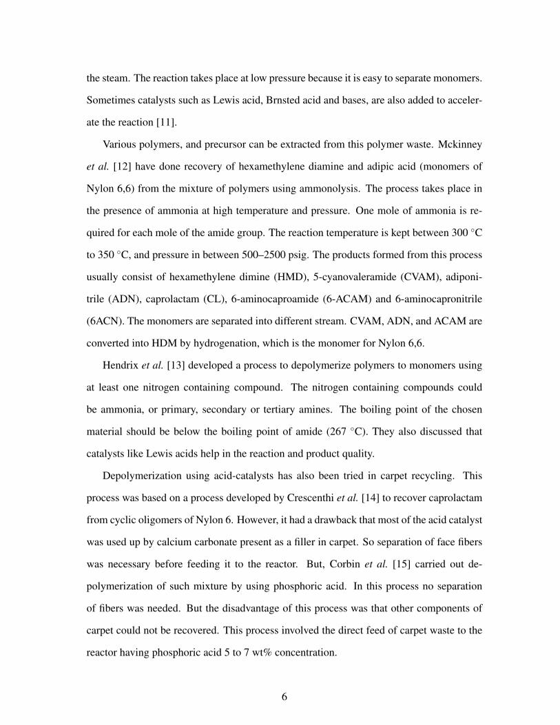
3.7.3 Surface Roughness
Atomic Force Microscopy (AFM) was used to observe the change in the surface rough-
ness of the fibers after treatment. An MFP-3DTM Stand Alone AFM (Asylum Research,
Santa Barbara, CA), was used to take images in the dual-AC mode. Figure 3.10 shows
the roughness of a virgin fiber and a fiber treated with methanol and sodium hydroxide. A
significant change on the surface of the fibers was seen. It could be seen that the fibers were
more rough after the surface treatment. The root mean square (RMS) values of the height
of the surface roughness of the virgin fiber was 13.9 nm, whereas RMS height values for
methanol and sodium hydroxide treated fibers were 15.4 nm and 20.1 nm, respectively.
This could help in an increase in the friction between matrix and the fibers, and hence re-
sults in better load transfer from matrix to fibers. So, not only the change in the chemistry
of the Nylon 6,6 fibers was observed, but the surface roughness was also changed.
3.7.4 Density and Porosity of Fabricated Laminates
The density and the porosity of the samples fabricated after surface treatment were mea-
sured using the same method as discussed earlier in chapter 2. Table 3.4 shows the bulk
41
(a) AFM image of a virgin fiber. (b) AFM image of a fiber treated with
methanol.
(c) AFM image of a fiber treated with
sodium hydroxide.
Figure 3.10: Atomic force microscopy image comparison of the roughness of a virgin fiber
and a fiber treated with Methanol and sodium hydroxide (0.5 M).
42

density, solid density, and porosity of the composites fabricated.
Table 3.4: Density an porosity values of carpet composites fabricated using the VARTM
technique after surface treatment.
Samples Treating agent Bulk density Solid density Porosity
(gms/cm3) (gms/cm3) (%)
FBBF - 1.2±0.01 1.16±0.01 4±0.7
MEOH-FBBF Methanol 1.4±0.02 1.369±0.02 2±0.08
IPA-FBBF Isopropylalcohol 1.2±0.01 1.17±0.01 2.4±0.08
NaOH-FBBF Sodium hydroxide (0.5 N) 1.4±0.02 1.372±0.03 2±0.06
KOH-FBBF Potassium hydroxide (0.5 N) 1.3±0.03 1.27±0.02 2.3±0.06
The density measurement shows that an increase in density of the samples was achieved
after surface treatment. The reason for this could be more resin material was infused
through the carpet fibers, which resulted into less amount pores in the composite. The
porosity also decreased, which further indicated the increase in the wetting of the fibers by
the resin material. The improvement in wetting of the fibers could be due to the chemical
change in the fibers or the increase in the surface roughness.
3.7.5 Flexural properties
The mechanical properties are listed below in the Table 3.5 and Fig. 3.11 shows the stress-
strain behavior of the composites fabricated after the surface treatment. The results showed
an increase in the values of flexural strength and the modulus. Composites treated with
methanol has shown an increase of ∼28% in flexural strength and ∼38% increase in flexu-
ral modulus. Similar results were obtained in case of treatment with potassium hydroxide.
The composite treated with sodium hydroxide had shown an increase of ∼39% in flexural
strength and an increase of ∼52% in flexural modulus. This increase in flexural modulus
indicated the better fiber wetting and more and more resin sticking around the fiber. The
43

porosity in case of sodium hydroxide seemed to have lowered, which substantiated this
increase in flexural modulus.
Table 3.5: Mechanical properties of the composite panels.
Sample name Treating agent Flexural strength Flexural modulus
(MPa) (MPa)
FBBF None 27.4±0.7 1722±41
MEOH-FBBF Methanol 35.2±0.5 2364±29
IPA-FBBF Isopropylalcohol 32.5±0.6 2152±37
NaOH-FBBF Sodium hydroxide (0.5 N) 38.6±2.1 2631±65
KOH-FBBF Potassium hydroxide (0.5 N) 35.6±1.1 2348±38
Figure 3.11: Stress-strain curves of the composites fabricated after surface treatment.
3.7.6 Failure Characterization
Figure 3.12 shows the difference in the crack developed in two composite samples, treated
and untreated, when loaded to failure in a three-point bend test. The composite which was
44

not treated prior to resin infusion, Fig. 3.12, had no interaction with resin, while the com-
posite which was treated after before resin infusion, showed a fiber alignment even after
failure indicating, a better interaction of fibers with matrix. This lead to a higher modulus
of the composites fabricated after the surface treatment. SEM images were collected of
the fibers at the cracked surfaces of the composites with surface treatment and without the
surface treatment. The micrograph in Fig. 3.13 show the image of a fiber at the fracture
surface for a sample with surface treated fibers. It is apparent that the fiber was surrounded
by the resin material indicating a better adhesion between the fiber and the resin. So an
improvement in the extent of fiber wetting has been obtained by surface treatment which
has helped in improving the mechanical properties of the composites.
(a) Crack developed in the composite
(untreated), when loaded to the failure
in three point bend test.
(b) Crack developed in the composite
(treated), when loaded to the failure in
three point bend test.
Figure 3.12: The crack developed in the composite samples when loaded to failure in a
three-point bend test.
45
Figure 3.13: Scanning electron micrograph of the treated fibers composite at the fractured
surface.
3.7.7 Possible Mechanism
For an aftermath of all the surface treatment work above, FTIR of the cured samples with
and without surface treatment were taken, to see any differences in the chemical interaction
between the vinyl ester matrix and the fibers. Small pieces of nylon fibers cured with vinyl
ester resin samples were crushed using liquid nitrogen into powder form. Then the FTIR
of these samples were collected. A noticeable change in the region from 2000 to 500 cm−1
was observed. Figure 3.14 shows the two FTIR spectrum of the two treated and untreated
samples.
To put together a proper mechanism of interaction between fibers and matrix, the struc-
ture of vinyl ester had to be determined. Since the resin used was proprietary, the exact
structure could not be known. So the FTIR of the resin was also taken to compare it vinyl
ester resin generally used and whose structure is known. Figure 3.15 shows the comparison
of the FTIRs taken for the resin used in current study and the vinyl ester resin used by Rosu
et al. [5]. It was reported that generally vinyl ester resins are manufactured by addition
46

(a) FTIR spectra of the untreated nylon fibers,
vinyl ester cured samples.
(b) FTIR spectra of the treated nylon fibers, vinyl
ester cured samples.
Figure 3.14: FTIR spectra comparison of untreated and treated fibers, when cured the vinyl
ester resin.
of unsaturated monocarboxilic acids to an epoxy backbone, in presence of a basic cata-
lyst [5]. Equation 3.16 shows the structure of the vinyl ester resin proposed in the paper.
The FTIR spectra shown by Rosu et al. has absorption peaks due to the carbonyl group at
1718 and 1180 cm−1. Also it has C=C stretching and wagging vibrations peaks at 1636 and
944 cm−1 respectively. The peak at 1636 cm−1 obtained is overlapped by the peak due to
styrene double bond absorption peak. The broad absorption around 3200–3600 cm−1 was
due to hydroxyl group. All these peaks could be found in the FTIR spectra of the resin used
in current study. So we could predict the structure of resin used having a carbonyl group,
C=C group, and styrene group.
Methyl ether ketone peroxide (MEKP) was used as a hardener to begin the curing of
resin. Now a possible mechanism of bonding between the fibers and matrix could be pro-
posed in which the C=C group at the ends of the chain took part in the reaction with the
carbonyl group in amide group. Figure 3.17 shows a crude approximation of the interac-
tion of vinyl ester resin and the amide group after the treatment with methanol. The C=C
interacted with the Ca ion which had formed a complex with amide group.
Another possibility of reaction is shown in Fig. 3.18, in which the carboxylic group of
47

(a) FTIR spectra of the vinyl ester resin used in cur-
rent study.
(b) FTIR spectra of the treated nylon fibers, vinyl
ester cured samples.
Figure 3.15: FTIR spectra comparison of vinyl ester resin used in current study and the
vinyl ester resin used by Rosu et al. [5] to confirm the structure of the resin.
Figure 3.16: Structure of the resin proposed by Rosu et al. [5], prepared by addition of
monocarboxilic acid and an epoxy backbone.
48

Figure 3.17: A proposed possible mechanism of interaction of vinyl ester resin with the
nylon 6,6 molecule treated with methanol.
vinyl ester formed a bond with Ca ion present on the amide chain.
There was no heat provided to the system while soaking any of the surface treating
agent. It was believed that the longer duration of soaking period might have helped in modi-
fying the surface chemistry. Their is another possibility of methanol forming a methaoixide
group with calcium i.e. CH3—O—Ca. Then this methaoxide forming a complex with the
carbonyl group of amide, hence breaking the —C=O—NH— hydrogen bond. This com-
plex might then interact with the vinyl ester resin as shown in Fig. 3.19.
3.8 CONCLUSIONS
The effect of the surface treatment of the carpet fibers on the mechanical properties prior to
resin infusion was studied. It was found that treating fibers with alcohols such as isopropyl
alcohol, methanol, and ketones such as acetone improves the flexural strength, around, by
30%. Also the FTIR spectra of the treated fibers were collected and it was observed that,
surface treatment modifies the surface chemistry resulting in the better adhesion between
49

Figure 3.18: Second proposed possible mechanism of interaction of vinyl ester resin with
the Nylon 6,6 molecule treated with methanol.
Figure 3.19: Third proposed possible mechanism of interaction of vinyl ester resin with the
Nylon 6,6 molecule treated with methanol.
50

matrix and the fiber. SEM micrographs clearly showed the difference in the texture of the
fibers at the crack surface of treated composites and untreated composites.
51

CHAPTER 4
CONCLUSIONS
In the current work, vacuum assisted resin transfer molding (VARTM) was used to fab-
ricate engineered composite materials from post-consumer carpet waste. This fabrication
technique did not require de-polymerization or melt blending, or any other processes. This
method also avoided the requirement of mechanical separation of face fibers for raw ma-
terial collection. Hence, the main advantage of this method was that it was simple. It also
took the advantage of material architecture to provide properties that could be advanta-
geous.
The composites fabricated using the VARTM based technique outperformed the previ-
ous preparation methods. The flexural strength of the composites was mainly dominated
by the type of matrix used. Both SC 79 and vinyl ester gave almost equal flexural modulus
in both type of configuration. That means either of the matrix system could be used to
fabricate composites from waste carpet. It would be better to use vinyl ester because it is
cheaper than SC 79 and it also does not require high temperature curing.
Failure characterization of the composites showed that there was no adhesion between
untreated fibers and the matrix. This could be because nylon fibers have high chemical
resistance and also because they were pretreated with certain chemical and dyes. So it be-
came imperative to modify the chemistry or the surface properties of the fibers to enhance
the bonding between the matrix and the fibers. So the carpet was treated with various sol-
vent before resin infusion. FTIR of the fibers showed considerable changes in the chemistry
of the fibers. This lead to a better bonding between fibers and matrix. A small increase in
the density, and around 50% decrease in porosity was also seen. The decrease in porosity
52

showed better wetting of fibers. Atomic force microscopy was done to observe any change
on the surface of the fibers, and an increase in the surface roughness was seen. Surface
treatment of fibers seemed to improve the flexural strength by 38% and flexural modulus
by 52%, through better fiber-matrix adhesion.
53

BIBLIOGRAPHY
[1] V. Moody and H. L. Needles, “Tufted carpet - textile fibers, dyes, finishes, and pro-
cesses.,” pp. 83–91, 2004.
[2] D. Mancosh, J. Przybylinski, and D. Murdock, “Carpet waste composite,” U.S. Patent
11/846865, p. , 2007.
[3] H. Bockhorn, S. Donner, M. Gernsbeck, A. Hornung, and U. Hornung, “Pyrolysis of
polyamide 6 under catalytic conditions and its application to reutilization of carpets,”
JOURNAL OF ANALYTICAL AND APPLIED PYROLYSIS, vol. 58, pp. 79–94, APR
2001.
[4] J. Miller and E. Bartick, “Forensic analysis of single fibers by Raman spectroscopy,”
APPLIED SPECTROSCOPY, vol. 55, pp. 1729–1732, DEC 2001.
[5] L. Rosu and D. Rosu, “Vinyl ester matrix resins for advanced materials,” JOURNAL
OF OPTOELECTRONICS AND ADVANCED MATERIALS, vol. 10, pp. 3377–3381,
DEC 2008.
[6] Available:, “http://www.carpetrecovery.org/index.php,” jun 2009.
[7] A. report, “Municipal solid waste in the united states,” November 2008.
[8] D. Mcintyre, G. Carpenter, and R. Powell, “Process for recycling fiber material and
binder with novel injection mold and parts made thereby,” september 2007.
[9] M. Braun, A. Levy, and S. Sifniades, “Recycling nylon 6 carpet to caprolac-
tam,” POLYMER-PLASTICS TECHNOLOGY AND ENGINEERING, vol. 38, no. 3,
pp. 471–484, 1999.
54

[10] D. Young, S. Chlystek, and J. Rice, “Recycling of carpet scrap and compositions
employing ultralow density polyethylene (uldpe),” US patent.
[11] S. Agrawal, “Depolymerization of nylon 6 to caprolactam,” Popular Plastics, 1975.
[12] R. Mckinney, “Ammonolysis of nylon,” US patent 5302756, 1994.
[13] J. Hendrix, Y. Frentzen, and N. DSM, “Depolymerization of polyamides,” US patent
5668277, 1997.
[14] L. Crescentini, W. Blackman, JA, J. DeCaprio, R. Fisher, R. Lffley, and J. Wagner,
“Recovery of caprolactam from nylon 6 oligomers,” US patent 4311642, 1982.
[15] T. Corbin, E. Davis, and J. Delhger, “Reclaiming epsilon-caprolactam from nylon 6
carpet,” US patent 5169870, 1992.
[16] E. Moran, “Conversion of nylon 6 and/or nylon 6.6 to monomers,” US patent
5310905, 1994.
[17] W. Nielinger, E. Ostllnning, and H. Buysch, “Production of caprolactam by thermal
depolymerization of polyamide 6,” US patent 5233037, 1993.
[18] T. Jenczewski, L. Crescentini, and R. Mayer, “Monomer recovery from multi-
component materials,” US patent 5656757, 1997.
[19] S. Czernik, C. Elam, R. Meglen, R. Moens, and K. Tatsumoto, “Pyrolysis of nylon 6
to recover caprolactam,” Analytical and Applied Pyrolysis, pp. 46–51, 1998.
[20] P. M. Subramanian, “Recovery of polyamide using a solution process,” US patent
5430068, p. , 1995.
[21] R. E. Stefandl, “Carpet recycling process for nylon containing carpeting,” W.O. Patent
98/35998, p. , 1998.
55

[22] M. E. Sikorski, “Recycling of polymeric materials from carpets and other multi-
component structures by means of supercritical fluid extraction,” U.S. Patent
5233021, p. , 1993.
[23] A. Griffith, Y. Park, and C. Roberts, “Separation and recovery of nylon from car-
pet waste using a supercritical fluid antisolvent technique,” POLYMER-PLASTICS
TECHNOLOGY AND ENGINEERING, vol. 38, no. 3, pp. 411–431, 1999.
[24] J. A. E. Hagguist and R. M. Hume, “Carpet reclaimer,” U.S. Patent 5230473, p. ,
1993.
[25] S. P.C., “Method for recycling carpet forming components from waste carpet,” U.S.
Patent 5518188, p. , 1996.
[26] R. Sferrazza, A. Handermann, C. Atwell, and D. Yamamoto, “Carpet recycling pro-
cess and system,” U.S. Patent 5535945, p. , 1996.
[27] Y. Zhang, J. Muzzy, and S. Kumar, “Recycling carpet waste by injection and com-
pression molding,” POLYMER-PLASTICS TECHNOLOGY AND ENGINEERING,
vol. 38, no. 3, pp. 485–498, 1999.
[28] R. DATTA, M. POLK, and S. KUMAR, “REACTIVE COMPATIBILIZATION OF
POLYPROPYLENE AND NYLON,” POLYMER-PLASTICS TECHNOLOGY AND
ENGINEERING, vol. 34, no. 4, pp. 551–560, 1995.
[29] S. Dagli, M. Xanthos, and J. Biesenberger Emerging Technologies in Plastics Recy-
cling, p. 240, 1992.
[30] Y. Wang, “Utilization of recycled carpet waste fibers for reinforcement of concrete
and soil,” POLYMER-PLASTICS TECHNOLOGY AND ENGINEERING, vol. 38,
no. 3, pp. 533–546, 1999.
56

[31] C. Mihut, D. Captain, F. Gadala-Maria, and M. Amiridis, “Review: Recycling of
nylon from carpet waste,” POLYMER ENGINEERING AND SCIENCE, vol. 41,
pp. 1457–1470, SEP 2001.
[32] ASTMD790-07, “Standard test methods for flexural properties of unreinforced and
reinforced plastics and electrical insulating materials,” ASTM International, 2007.
[33] B. David and E. Roslyn U.S.P., pp. 340–480, July 1982.
[34] M. Sanjo and M. Kaneko J.P., pp. 58–94863, June 1983.
[35] O. Stousland and N. Burlington U.S.P., pp. 482–594, November 1984.
[36] H. Mark, “Encyclopedia of polymer science and technology,” John Wiley and Sons
Inc., p. , 1989.
[37] G. Gocan Romanian Patent, p. , 1981.
[38] B. Sun, “Study on the mechanism of nylon 6, 6 dissolving process using cacl2/meoh
as the solvent,” Chinese Journal of Polymer Science, pp. 57–65, 1994.
[39] M. Roberts and S. Jenekhe Chem. Mater., pp. 224–226, 1990.
[40] “Melins handbuch der anorganischem,” Calcium, Verlag chemie, Gmbh, Wein-
heim/Bergstrasse, pp. system–number 28, 1957.
[41] W. Moor and S. Krimm Biopolymers, p. 2439, 1976.
[42] D. GARCIA and H. STARKWEATHER, “HYDROGEN-BONDING IN NYLON-
66 AND MODEL COMPOUNDS,” JOURNAL OF POLYMER SCIENCE PART B-
POLYMER PHYSICS, vol. 23, no. 3, pp. 537–555, 1985.
[43] M. ENSANIAN, “CATASTROPHIC FAILURE OF HIGH-STRESSED NYLON BY
CONCENTRATED HYDROCHLORIC ACID AND OF PLEXIGLAS BY ALLYL-
BROMIDE,” NATURE, vol. 193, no. 4811, pp. 161–&, 1962.
57

[44] P. Hamm, M. Lim, and R. Hochstrasser, “Structure of the amide I band of peptides
measured by femtosecond nonlinear-infrared spectroscopy,” JOURNAL OF PHYSI-
CAL CHEMISTRY B, vol. 102, pp. 6123–6138, JUL 30 1998.
[45] J. HIRSCHINGER, H. MIURA, K. GARDNER, and A. ENGLISH, “SEGMENTAL
DYNAMICS IN THE CRYSTALLINE PHASE OF NYLON-66 - SOLID-STATE H-
2 NMR,” MACROMOLECULES, vol. 23, pp. 2153–2169, APR 16 1990.
[46] M. COLEMAN, D. SKROVANEK, and P. PAINTER, “HYDROGEN-BONDING
IN POLYMERS .3. FURTHER INFRARED TEMPERATURE STUDIES OF
POLYAMIDES,” MAKROMOLEKULARE CHEMIE-MACROMOLECULAR SYM-
POSIA, vol. 5, pp. 21–33, SEP 1986.
[47] A. DONG, P. HUANG, and W. CAUGHEY, “PROTEIN SECONDARY STRUC-
TURES IN WATER FROM 2ND-DERIVATIVE AMIDE-I INFRARED-SPECTRA,”
BIOCHEMISTRY, vol. 29, pp. 3303–3308, APR 3 1990.
[48] Y. Wu, Y. Xu, D. Wang, Y. Zhao, S. Weng, D. Xu, and J. Wu, “FT-IR spectroscopic
investigation on the interaction between nylon 66 and lithium salts,” JOURNAL OF
APPLIED POLYMER SCIENCE, vol. 91, pp. 2869–2875, MAR 5 2004.
[49] N. Vasanthan, R. Kotek, D. Jung, D. Shin, A. Tonelli, and D. Salem, “Lewis acid-
base complexation of polyamide 66 to control hydrogen bonding, extensibility and
crystallinity,” POLYMER, vol. 45, pp. 4077–4085, MAY 20 2004.
[50] F. WALL and P. SAXTON, “ELECTROLYTIC INTERACTION OF NYLON WITH
SODIUM HYDROXIDE SOLUTIONS AT DIFFERENT TEMPERATURES,”
JOURNAL OF PHYSICAL CHEMISTRY, vol. 57, no. 3, pp. 370–375, 1953.
[51] C. Pouchert, “The aldrich library of ft-ir spectra,” Aldrich, p. , 1985.
58

[52] J. L. Koenig, M. Ipekci, and J. B. Lando, “The aldrich library of ft-ir spectra,” p. 713,
1972.
[53] D. J. Skrovanek, P. C. Painter, and M. Coleman, “Macromolecules,” pp. 19–699,
1986.
[54] K. Mukae, S. Sakurai, S. Sawamura, K. Makino, S. Kim, I. Ueda, and K. Shirahama
Japanese journal for physical chemistry, p. 737, 1993.
[55] C. R. Kemnitz and M. J. Loewen, ““Amide resonance” correlates with a breadth
of C-N rotation barriers,” JOURNAL OF THE AMERICAN CHEMICAL SOCIETY,
vol. 129, pp. 2521–2528, MAR 7 2007.
[56] N. Allinger, M. Cava, and D. DeJongh, “Organic chemsitry,” p. , 1971.
59

VITA
Abhishek Jain
Candidate for the Degree of
Master of Science
Thesis: EFFECT OF FIBER SURFACE TREATMENT IN CARPET RECYCLING
Major Field: Mechanical and Aerospace Engineering
Biographical:
Personal Data: Born in Ratlam, India on September 22nd, 1986.
Education:Received the B.E. degree from Medicaps Institute of Technology and Manage-ment, Indore, India, 2008, in Mechanical EngineeringCompleted the requirements for the degree of Master of Science with a majorin Mechanical Engineering Oklahoma State University in June 2010.
Experience:Worked as a Graduate Research Assistant at the Mechanics of Advanced Ma-terials Laboratory headed by Dr. Raman P. Singh in the area of polymer rein-forced composites
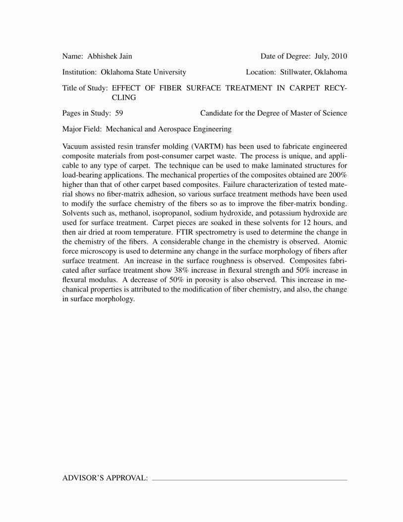
Name: Abhishek Jain Date of Degree: July, 2010
Institution: Oklahoma State University Location: Stillwater, Oklahoma
Title of Study: EFFECT OF FIBER SURFACE TREATMENT IN CARPET RECY-CLING
Pages in Study: 59 Candidate for the Degree of Master of Science
Major Field: Mechanical and Aerospace Engineering
Vacuum assisted resin transfer molding (VARTM) has been used to fabricate engineeredcomposite materials from post-consumer carpet waste. The process is unique, and appli-cable to any type of carpet. The technique can be used to make laminated structures forload-bearing applications. The mechanical properties of the composites obtained are 200%higher than that of other carpet based composites. Failure characterization of tested mate-rial shows no fiber-matrix adhesion, so various surface treatment methods have been usedto modify the surface chemistry of the fibers so as to improve the fiber-matrix bonding.Solvents such as, methanol, isopropanol, sodium hydroxide, and potassium hydroxide areused for surface treatment. Carpet pieces are soaked in these solvents for 12 hours, andthen air dried at room temperature. FTIR spectrometry is used to determine the change inthe chemistry of the fibers. A considerable change in the chemistry is observed. Atomicforce microscopy is used to determine any change in the surface morphology of fibers aftersurface treatment. An increase in the surface roughness is observed. Composites fabri-cated after surface treatment show 38% increase in flexural strength and 50% increase inflexural modulus. A decrease of 50% in porosity is also observed. This increase in me-chanical properties is attributed to the modification of fiber chemistry, and also, the changein surface morphology.
ADVISOR’S APPROVAL: