effect of draped reinforcement on behavior of …
TRANSCRIPT

10 .-,- "'') C! 11." -I- eX- ! ft
CIVIL ENGINEERING STUDIES STRUCTURAL RESEARCH SERIES NO. 154
~;/54 ",
~..:j PRIVATE COMMUNICATION ow NOT FOR PUBLICATION
EFFECT OF DRAPED REINFORCEMENT ON BEHAVIOR OF PRESTRESSED CONCRETE BEAMS
A Thesis
by J. G. MacGregor
Issued as a Part
of the
SEVENTH PROGRESS REPORT
of the
INVESTIGATION OF PRESTRESSED CONCRETE
FOR HIGHWAY BRIDGES
MAY 1958
UNIVERSITY OF ILLINOIS
URBANA, ILLINOIS


EFFECT OF DRAPED REINFORCEMENT ON BEHAVIOR
OF PRESTRESSED CONCRETE BEAMS
A Thesis by
Jo Go MacGregor
Issued as a Part of the Seventh Progress Report of the
INVESTIGATION OF PRESTRESSED CONCRETE
FOR HIGHWAY BRIDGES
Conducted by
THE ENGINEERING EXPERIMENT STATION
UNlVERS ITY OF ILLINOIS
In Cooperation With
TEE DIVISION OF HIGHWAYS
STATE OF ILLINOIS
and
Uo S. DEPARTMENT OF COMMERCE
BUREAU OF PUBLIC ROADS
Urbana J Illinois
June 1958


TABLE OF CONTENTS
I. INTRODUCTION
1.1 Introduction.
1~2 Object and Scope. " .
1·3 Acknowledgments "
1.4 Notation. . "' .
II. MATERIAIS, FABRICATION AND TEST SPECIMENS
2.1 Materials " . " . " • 0 0 •
2.2 Description of Specimens.. .
2.3 Prestressing and Draping"
2 .. 4 Casting and Curing.. .• .. •
III • INSTRUMENTATION, LOADING APPARATUS AND TEST PROCEDURE
IV.
3.1 Instrumentation. . . 0 •
3 .. 2 Loading Apparatus .
3.3 Test Pro.cedure .... ~ w' •
3.4 Measured and Derived Q,uantities ..
BEHAVIOR OF TEST BEAMS
4.1 Definition of Flexural and Shear Failures .
4.2 Flexural Failures .
Shear Failures.. 0 0
Behavior o:f Beams With All Draped Wires
0. • a e
Behavior of Beams With Both Straight and Draped Wires ..
Behavior of Beams With Web Reinforcement and Draped
Wires., .... " .... O''lI!'QoO·.·OOO .... _O(lo~O'D o· 0
iii
1
2
3
4
6
8
10
14
15
16
16
17
18
18
19
24
28


T.A:BLE OF CONTENTS (Continued)
v " DISCUSSION OF TEST RESULTS
5~l Basis f'or Quantitative Comparison of' Observed Inclined
Tension Cracking Loads ". .. ~ /I • • .. • ~ " .. .. 0 "' ..
5.2 Eff'ect of' Draped Reinforcement on Strength of Test
Beams at Inclined Cracking", a _ .. .. ... .. .. .. • .. •
5.3 Effect of' Draped Reinforcement on Ultimate Strength
of' a Prestressed Beam. • 0 <I Ii .. .. .. .. .. .. .. .. .. .. • .. 0 <I
VI .. SUMMARY. 0 • ..
VII.. BIJ3LIOGRAPHY c> . " ., .
iv
32
42
46
49


Table NCh.
l
2
3
4
5
6
LIST OF TABUS
Properties of Beams. co .. • • •
Properties of Drape Profiles 0
Sieve Analysis of Aggregates
Properties of' Cb:ncrete Mixes .....
Measured and Com.:puted Shears at Inclined Cracking
Load ... • • • D 0 0 ~ • • • " . Measured and Computed Moments ... • 00' • .' ... •
v
Page
50
51
52
53
54
55


Figure No",
1
2
3
4
5
6
7
8
9
10
11
12
13
14
15
16
17
18
19
LIST OF FIGURl!S
Nominal Dimensions of I -Beams <>
Drape- Profiles 0 • <> 0 <> ., 0 .. 0
Comparison of Modulus of' Rupture With Concrete
Strength • .. " .. 0' • .. ., .,
Stress.o.Strain Relationship for Lot XI Wire • ~ .. "
Stress-8train Relationship for Lot XII Wireo .,
Stress-Strain Relationship for Black Annealed Wire
Stirl"1l.I> Details ....
Draping Sadales ..
Cross-Sections nf Beam and FQrm~ 0
Location of Strain Gages ~
Details of TestingFTame
Load Deflection Curves for Beams Failing in Flexure.. •
Relation Between Critical Concrete and Steel Strains "
Initiating Crack Developing into a Major Inclin'ed
Crack 0 .. <> ",.. • .. • .. ' .. '.. .'.. ..
Initiating Crack Followed by a Major Inclined Crack.. •
Major Inclined Crack Originating in Web. " •••
Location of Initiating Cracks and Major Inclined
Tension Cracks " .. 0 •
Load Dei'lection Curves for Beams With All Wires
Draped - Beams With Eight Wires 0: , .. • .. .. " .. 0
Load Deflection Curves for Beams With All Wires
Draped - Beams With Six Wires.. ..
vi
58
59
60
61
62
63
64
65
66
67
68
72
73


Figure No'~
20
2l
22
23
24
25
26
27
28
LIST OF FIGURES (Continued)
Te-sting Procedure - Beams Ml2 and Ml2ao " 0 .. .. • ..
Load Deflection Curves for Beams With Both Straight
and Draped Wires" . 0 " .. " " 0 " " " 0 "
Load Deflection Curves for Beams With Web
Reinforcement c>
Effect of' Angle of Drape on Inclined Tension Cracking
Effect o.f Angle of Drape on Net Shear at Inclined
Tension Cracking., .. .. .." " • " " 0 0 ~ " "
Comparison of' Cracking Loads and Ultimate Loads for
Various Drape Angles .. ". " " " 0 .. <> " .,. 0 0- 0 ...
Ef'f'ect of Dra:ping on Principal Tensile Stresses at
Bottom of Web IY 0 0 • • .. • <> 0 <> .. G " " " o· "
Effect of Draping on Principal Tensile Stresses at
Top of Web ~ " " ..
Increase in Load After Inclined Cracking., 0
vii
Page
75
T7
79
80
81


I. INTRODUCTION
1.1 Introduction
Tests of over a hundred beams with straight longitudinal reinforce
ment and no web reinforcement, carried out in the earlier phases of this
investigation (1, 2, 3)*, showed that reinforcement should be provided to
resist inclined tension stresses as well as horizontal tension stresses.
Two different types of reinforcement are commonly used for this purpose:
stirrups, and draped reinforcement. The term lTdraped reinforcement" refers
to longitudinal reinforcement which is curved in elevation in the shear spanso
At the supports the centroid of draped reinforcement is closer to the top of
the beam than it is at midspan.. Stirrups of various grades of steel and of
various shapes are used solely to carry l'shearn. On the other hand, the
longitudinal reinforcement may be draped, primarily to relieve tension stresses
in the top flange or compression stresses in the bottom flange or to alleviate
anchorage stresses. The slope of the tendons results in an upward component
of the prestressing force which is customarily subtracted from the total down
ward shear acting on the section.
The investigation of the effect of vertical stirrups on the strength
and behavior of prestressed concrete beams has been initiated by Mr. Go
Hernandez whose findings are reported in a thesis published as a part of the
Seventh Progress Report of the Investigation of Prestressed Concrete for
Highway Bridges (4). The work described in this report has been undertaken
to determine whether draped reinforcement improves the strength and behavior
of prestressed concrete beams.
* Numbers in parent~~~es refer to entries in the Bibliography.

2
1~2 Object and Scope
The object of this report is to describe and discuss the results of
tests on sixteen simply supported pretensioned concrete beams with varying
degrees of drape.
The overall cross-sectional dimensions for the beams were 6by
12 in. There were 14 I-beams with 3-in~ webs, one I-beam with a 1 3/4-in.
web and one rectangular beam. All the beams were tested to failure with
loads applied at the third-points of a 9-ft. spano The prestress and concrete
strength were approximately 115,000 psi and 3,000 psi, respectively, in all
beams. Vertical stirrups were used in two beams. The nominal dimensions are
shown in Figo 1, and the properties of the beams are listed in Table 10
The principal variable in the test series was the profile of the
prestressing steel 0 In all, nine different profiles were used as outlined in
Table 2 and shown in Figo 2~ Those designated A through E had all the wires
draped at the same angle in each shear span and those designated X throughZ
had only part of the wires drapede Profile S had only straight wires.
The drape profile used in an actual bridge member will depend on
such factors as the method of prestressing, the method of draping, and the
strength requirements of the finished structure. For this reason, several
types of drape profiles, each quite different, are commonly used. In order to
limit the number of variables, only the two basic types of drape profiles
shown on Fig. 2 have been used in these tests. These were made up entirely of
straight line segments, all the wires being level and parallel in the center
third of the beamo In each case, the wires were bent at the load points.
Although it is not customary to drape all the reinforcement in a
beam, this was done in ten of the test beams to isolate the effect of draped
wires alone. Six different drape angles were used, varying from zero to ten

3
degrees. The behavior of a beam with both straight and draped wires should
lie somewhere between the extreme conditions of a beam with straight wires only
and one with draped wires only.. To confirm this idea, four beams with only
some of the wires draped were tested ..
103 Acknowledgments
The studies reported herein were made as a part of an investigation
of prestressed ~einforced concrete for highway bridges conducted by the
Department of Civil Engineering of the University of Illinois in cooperation
with the Division of Highways, State of IllinOiS, and the U. So Department
of Commerce, Bureau of Public Roadso
The program of the investigation has been guided by an advisory
committee on which the following persons have served during the period covered
by the work described in this report: E. Lo Erickson and Harold Allen, repre
senting the Bureau of Public Roads; W. E. Chastain, Sr.; W. J~ Mackay, and
Co Eo Thunman, Jro, representing the Illinois Division of Highways; and C. Po
Siess and N. Khachaturian representing the University of Illinois.
The project has been under the general direction of Dr. C. Po Siess
and the immediate direction of Dr. M. A. Sozeno
This report was written as a thesis under the direction of Dr. Siess,
and his assistance in planning the tests and his helpful comments are grate
fully acknowledged. Credit for assistance in the development of e~uipment
and analYSis and critical study of the manuscript of this report is due Dr. M.
Ao Sozen. Appreciation is expressed to Co J. Fleming, N.· Mo HaWkins, Research
Assistants in Civil Engineering and G. Tiezzi, Student, for their aid in con
ducting the tests, reducing data and preparing figureso Special thanks are
given to Wyck McKenzie, Junior Laboratory Mechanic in Civil Engineering, for
his aid in fabricating specimens and e~uipment.

4
The wire reinforcement was furnished without charge by the American
Steel and Wire Division of the United States Steel Corporation.
1.4 Notation
The symbol ~ is used for moments on a beam and V denotes the shear
in one shear span. These symbols may have the subscripts: £, referring to
conditions at the formation of the inclined crack; ~, referring to the upward
force caused by draping the wires; !, referring to the computed flexural capa-
city of the beams; and ~, referring to the conditions at ultimate loads. The
symbol! is used for stresso
Cross-Sectional Constants and Beam Properties
A gross area of cross section c
A total area of longitudinal reinforcement s
A area of one stirrup v
b top flange width
bY web thickness
d effective depth of the reinforcement in the flexure span
E modulus of elasticity of steel s
s spacing of stirrups
~ angle of drape = angle between the horizontal and the draped wires
Loads and Stresses
f! C
f r
f se
compressive strength of concrete determined from 6- by l2-in. control cylinders
modulus of rupture of concrete determined from 6- by 6- by 24-in. control beams loaded at the third-points over an IS-in. span
effective prestress
f = assumed tensile strength of concrete t
F effective prestressing force se

M c
M' c
p c
v c
applied bending moment at inclined tension cracking
computed bending moment at inclined tension cracking for a beam with straight longitudinal reinforcement
ultimate bending moment for flexural failure
ultimate moment measured in test
applied load at inclined tension cracking
applied load at flexural failure
applied load at ultimate load
applied shear at inclined tension cracking
upward component of prestressing force
net shear or effective shear at inclined cracking
Dimensionless Quantities
p
Q
r
A /bd = reinforcement ratio s
E P/f 1
S c
A /b 1 = web reinforcement ratio v s
5

6
II. MATERIAIB , FABRICATION, AND TEST SPECIMENS
2.1 Materials
( a). Cement . Mar~uette Type III Portland Cement was used for all
the beams presented in this report. All the cement was purchased in paper
bags from local dealers and stored under proper conditions.
(b) Aggregates. Wabash River sand and pea gravel were used in all
the beams. Both aggregates have been previously used in the laboratory and
have Fassed the usual specification tests. The maximum size of the gravel
was 3/S in.. The absorption of both fine and coarse aggregate was about one
percent by weight of the surface dry aggregate. Sieve analyses of the aggre-
gates are given in Table 3.
The aggregates were :from a glacial outwash of the Wisconsin glacia-
tiona The major constituents of the gravel were limestone and dolomite with
minor ~uantities of ~uartz, granite and gneiss. The sand consisted mainly of
~uartz .
(c) Concrete Mixes. Concrete mixes were designed by the trial batch
method for a seven-day compressive strength of 3,000 psi and a slump of 3 in.
Two batches were used in each beam, Batch I being in the lower half of the
beam. Table 4 lists the proportions of the concrete batches used in each
beam along with the slump, compressive strength, modulus of rupture, and age
of test. Proportions are in terms of oven dry weights.. The compressive
strength, fT, is the average strength of a minimum of four 6- by 12-in. control c
specimens. Values reported for the modulus of rupture, f , are results of r
tests of 6- by 6- by 20-in. control beams loaded at the third-points of an
IS-in. span. The concrete strength and modulus of rupture were determined
immediately after testing each beamo

7
In Fig. 3, the moduli of rupture are compared with compressive
strengths. Since a measure of the tensile strength of the concrete in each
beam was necessary for the interpretation of the test results, and since the
scatter in the data did not warrant the use of the results of individual
control beams, the statistical expression used by Sozen (3) was selected to
reIJresent the test data. For concrete with small-size coarse aggregate this
expression was:
f r
3,000
4 + 12,000 f'f
c
(1)
The tensile strength of' the concrete is assumed to be two-thirds of the modulus
of rupture as expressed by Equation (1), since no tests were made to determine
the tensile strength directly.
(d) Prestressing~· Wire.. Steel designated as Lot XI and Lot XII
were used as prestressing reinforcement for the beams. This was manufactured
by the American Steel and. Wire Division of the United States Steel Corporation
and is designated by the manufacturer as "Hard Drawn Stress-Relieved Super-Tens
Wire". The following steps were involved in its manufacture: hot rolling, lead.
patenting, cold drawing, and stress relieving. The wire was delivered in coils
about 54 in. in diameter and weighing approximately 260 lb. The diameter of
the wire itself was measured to be 0.196 in. The following heat analyses
have been furnished by the manufacturer:
Lot No.
XI
XII
Carbon
0.85%
0.88%
Manganese
0.65%
0.79%
Phosphorus
0.010%
0.024%
Sulfur
0.027%
0.033%
Silicon
0.18%
0.25%

8
To improve the bond characteristics, all wires were first wiped with
a cloth dipped in a hydrochloric acid solution and then placed in the moist
room for a week to rust. This operation produced a slightly pitted surface.
Insulating tape was wrapped around the wire at the intended locations of
electric strain gages before rusting. All wires were cleaned with a wire
brush just before use to remove loose rust ..
Samples cut from different portions of the roll were tested in a
l20;000-lb capacity Baldwin hydraulic testing machine. Strains were measured
with an 8-in. extensometer employing a Baldwin Hmicroformer rT coil and were
recorded by an automatic recording device. The extensometer was removed from
the specimen at about 2D5 percent strain to prevent damage to the instrument~
The average stress-strain relationships for Lot XI and Lot XII wires are shown
in Figs. 4 and 5.
(e) Stirrup Wire. Bea~ MlO and Mll had Noo 8 black annealed wire
stirrups. The wires were rusted and samples were tested in the same way as
indicated for the prestressing steel~ The stress-strain relationship for
this wire is shown in Fig. 6.
2.2 Description of Specimens
All the test beams were 10 ft long and nominally 6 by 12 in. in
cross-section. Fourteen beams had 3-in. webs, one had a 1 3/4-in. web and
one was rectangular in cross-section. The nominal dimensions are shown on
Fig. 1. The end blocks were about 12 in. long. The beams without web rein
forcement had prestressed external stirrups to prevent complete failure of
the end block. Two of these stirrups were used in each beam; one at each end
immediately on the outside of the reaction block.
Single wire reinforcing was used in all beams. The minimum vertical
and horizontal spacing between these wires was maintained at 0.75 in. and

0.70 in. respectively. This spacing corresponds to that used by Sozen (3)
and Hernandez (4). In all cases the wire profiles consisted entirely of
straight line segments, the wires being bent only at the end plates and at
the third-points of the spano In all beams the prestressing wires were
parallel and horizontal in the flexure span. The center of gravity of the
wires in the flexure span was at two inches above the bottom of the beam
unless otherwise noted below. For the beams with eight wires, the lowest
wires were thus 1 5/8 in. above the bottom of the forms while in the beams
with six wires this distance was 1 3/4 ino
9
The prestressing wires were either all draped parallel to one
another or some of the wires were draped and the rest of the wires straight ..
In all, nine drape profiles were used. These are described in Table 2 and
Fig. 2 and will be referred to using the letter symbols given there. The
center of gravity of the longitudinal steel over the support for drape pro
files B, C and E passes through the lower kern point, the mid-height and the
upper-kern point of the I-section, respectively. In the following sections
these p~~icular profiles are sometimes referred to in short as lower kern
point ir~pe, mid-height drape, and upper kern point drape.
~~: reinforcement was used in beams MlO and Mllo The spacing and
dime:-l~::;~.:-:;: the stirrups are shown in Fig. 7. The details of the stirrups
were 2r.:J~~>'::: :'0 be similar to those in beams G19 and G30 tested by Hernandez
(4). :':.1::' lJ2~~ion of each stirrup was shifted 2 1/2 in. from the correspond
ing pos i:., i 0:-. in G19 and G30" The spacing was kept at 5 in 0, however.
In general~ bridge members have a greater span to depth ratio than
the beams in this test series~ This) in turn, restricts the angle of drape
possible in a bridge beam" The maximmn angle of drape used in the Northern
Illinois toll-road bridges was approximately 8.25 deg. with the horizontal

for the draped wires 7 but only about 1.67 deg. for the center of gravity of
all the steel. The cross-section of the test beams are similar to bridge
beams except that the latter usually have cast-in-place decks. The ratios
of web thickness to lower flange thickness of the AABRO standard sections
range from 0.30S to 0 .. 375 compared to 0.50 for the 3-in. I-beams of this
test series and 0.29 for the 1 3/4-in. I-beam.
2.3 Prestressing and Draping
10
( a) End Details of Wires. A threaded end anchorage was used on
the wires of all the beams during the prestressing operation. After release,
no end anchorages were used. The threaded anchorages consisted of a special
heat-treated nut screwed on the threaded end of a prestressing wire. Wires
were threaded 24 threads to- the inch for about three inches on each end in
an automatic threading machine with specially heat-treated chasers. The
threads on the wires were cut to provide a medium fit with the threads in
the nuts.
The nuts were specially made in the laboratory machine shop. They
were subdrilled with a No. 16 tap drill and tapped with a standard No. 12,
24 threads to the inch, tap. The thread cut on the wires to fit a No. l2
thread in the nut was sufficient to develop at least 190 ksi in the wire.
The nuts were 5/S-in. long and hexagonal in cross-section. They
were made from hardened lfBustertf alloy punch and chisel steel having the
following composition limits: carbon, 0.56 to 0.60 percent; silicon, 0.60
to O.SO percent; chromium, 1.10 to 1.30 percent; tungsten, 2.00 to 2.30 per
cent; and vanadium, 0.20 to 0.30 percent.
(b) Tensioning Apparatus. Since the beams in this series were
all pre-tensioned, a prestressing frame was necessary to provide a reaction
for the tensioning force. The frame consisted of two -11 ft 6 in. lengths

11
of extra-heavy 3-ino diameter pipe and two bearing plates J 2 by 6 by 20 in~
It was built to fit around the form for the beam.. The bearing plates had six
rows of 0.206-in" diameter holes to accomodate the various positions of the
wires & The holes were 0.70 in. apart horizontally and 0.75 in. ve!tically.
A thirty-ton capacity Simplex center-hole hydraulic ram operated by
a Blackhawk pump was used to tension the wires. A U-shaped jacking frame
fitted between the pretensioning frame and the jack. To tension the wires the
ram reacted against the frame and a 5/8-in" diameter rod. The thrust was trans
ferred from the ram. to the rod through washers and a nut. The rod in turn ex
tended through the center hole in the ram and was directly connected to the
wires by means of a heat-treated nut welded to the rod. After the wire was
tensioned to the desired stress the nut on the wire was turned up against a
shim and the jack was released allowing the nut and shim to bear on the pre
tensioning frame.
(c) Draping Apparatus. The reinforcing wires were tensioned in
their uppermost position and then were pulled down to their final position by
two draping saddles, one at each third-point. The draping saddles consisted
of two long threaded 3/8-in. diameter rods with two 2 1/2-ino lengths of 1/2-in.
diameter rod we.lded across them at one end (see Fig. 8). The cross-bars and
the threaded vertical rods were dimensioned to allow the wires to pass between
them in their normal spacing. The lower ends of the vertical rods passed through
holes in the bottom of' th e form and the saddles were held in position by nuts
bearing on the bottom of the form. No provision was made for longitudinal move
ments of the wires during draping since the saddles were flexible enough in that
direction. This caused no trouble in draping the wires.
The form members rested on a stiffening beam built up from plates and
two 15-in. channels. The form and beam are shown in Fig. 9. This beam was

12
necessary to prevent the ~orms from warping when the prestressing wires were
draped.
For low drapes it was possible to do all. the draping by screwing nuts
onto the threaded rods. A hydraulic jack was used to pull down the saddles ~or
the higher drapes.
(d) Measurement of Prestressing Force. The tensioning force in each
wire was determined by measuring the compressive strain in cylindrical aluminum
dynamometers slipped on the wire between the nut and the bearing plate at the
end opposite to which the tension was applied. The dynamometer consisted of a
2-in. length of 1/2-in. aluminum rod with a 0.2-in. diameter hole drilled
through its center. Strains were measured by means of two Type A7 SR-4 elec
tric strain gages mounted on opposite sides of each dynamometer and wired in
series. This arrangement gave a strain reading which was the average of the
strains in the two gages thereby compensating for small eccentricities of load
that might occur. The dynamometers were calibrated using the 6000-lb range of
a 120~OOO-lb capacity Baldwin hydraulic testing machine 0 The calibration con
stants of the dynamometers were very nearly the same; the strain increment
necessary to ~easure a tensioning stress of 120 ksi in the wire was about 2000
milliontcs. This large increment of strain allowed a precise measurement of
stress i~ tje riires, since the strain indicator used had a sensitivity o~ two
S~~~l~s in the wires were measured by means of Type A-7 SR-4 electric
strain gage;:: :notL.'rJ.ted at various points along the beam. Measurements taken dur
ing draping showed that for all the beams instrumented in this waYJ the average
stress at the jacking end and at the dynamometer end were 100 and 101 percent,
respectively, of the stress in the flexure span. For this reason, beams M9
through Ml6 had electric strain gages at midspan only.

13
(e) Tensioning, Draping and Releasing Procedure. The longitudinal
reinforcement was tensioned in the prestressing frame prior to draping and cast
ing. The ends of the wires were slipped through the draping saddles, the end
plates of the form, and through the bearing plates of the prestressing frameo
The dynamometers were then slipped onto one end of the wires and the anchoring
nuts were put on each end of the wire. The wires were tensioned individually
to the desired stress less the increment of stress which would be added by
draping the wires. An allowance was made for the elastic shortening of the
prestressing frame. In drape profiles D andE, the draping process alone would
have stressed the wires to more than 120 ksi and it was necessary to release
some stress at intervals to maintain the desired prestress in the finished beam.
After initial tensioning, the prestressing frame and wires were trans
ported to the form and the ends of the saddles were fitted through holes in the
bottom of the form. The end plates were bolted to one side form to prevent
being pulled out of line during the draping procedure. The other side form was
not in place during draping to facilitate measurement of the height of the
wires. The wires were then pulled down into position with saddles ~ Dynamometer
and steel strain readings were taken before and after the draping operation~ As
noted in Section 2.3(d), there was no significant variation in stress from one
part of the beam to another.
Two days before testing, the tension was releasedJ ends first and
drape last. Dynamometer and steel strain readings were taken before and after
release.
Minor difficulties were encountered in prestressing the beams with
only some of the wires draped. Since the wires to be draped and the straight
wires were at opposite edges of the bearing plates, the bearing plates pivoted
slightly against the ends of the pipes as the straight wires were prestressed.

14
This trouble was most noticeable with drape profile Z in which the draped wires
gained most of their stress as they were deflected into position.
The force re~uired to drape the upper-kern point beams was practically
e~ual to the capacity of the threads of the draping saddles and in one case they
were stripped.
2 .. 4 Casting and Curing
All the beams in this test series were cast in metal forms. The side
forms were made from 12-in. channels bolted securely to the stiffening beam
described in 2.3(c). The form and stiffening beam are shown in Fig~ 9. Re
movable metal inserts bolted to the side forms were used to form the webs of
the beams tested.
All concrete was mixed from three to six minutes in a non-tilting
drum type mixer of six cubic feet capacity, and was placed in the form with
the aid of a high fre~uency internal vibrator. Each beam re~uired two batches,
the first batch filling the lower half of the beam. Six 6 by 12 in. control
cylinders and one 6 by 6 by 20 in. modulus of rupture beam were cast from each
batch.
Several hours after casting, the top surface of the beam was trowelled
smooth and the cylinders were capped with neat cement paste. The fOrmE of the
beam and control specimens were removed after one day and the beam and control
specimens were wrapped in wet burlap for several days~ The burlap was removed
three to five days before testing to allow the concrete surface to dry before
electric strain gages were applied.

15
III. INSTRlJMENTATION, WADING APPARATUS, AND TEST PROCEDURE
3.1 Instrumentation
Strains in the wires were measured with Type A-7 SR-4 electric strain
gages which have a nominal gage length of 1/4 in. and a minimum trim width of
3/16 in. They were chosen for their narrow width, short length, and flexibility.
The gages were placed at midspan on one wire in each layer of steel. In beams
Ml to M8 gages were also provided in the shear spans at three inches from the
point of draping. The location of the steel strain gages is shown in Fig. 100
The surface of the wire was prepared far gage application by using
fine emery cloth and acetone.. The gage was mounted with Duco cement. After
several hours of air drying, heat lamps were used to speed the drying of the
cement 0 Following this, while the wire was still warm7 a layer of wax was
applied on the gage to protect it from moisture. The gage was then wrapped
with one layer of electric tape. Lead wires were soldered on and the whole
assembly was wrapped again with electric tape. Because the beams were preten
sioned it was necessary to waterproof the gages carefully since they would be
i.n contact with wet concrete. Waterproofing was accomplished by pouring melted
petrolastic into a preformed tin container 1 1/2'bY 1/2 by 1/2 in. which was
attached to the reinforcing wire.
Strains in the concrete at the top of the beam were measured with
Type A-3 SR-4 electric strain gages. These gages had a nominal gage length
of 3/4 in. and a width of 3/8 in. A portable grinder was used to smooth the
top surface of the beam at the desired locations" A thin layer of Duco cement
was applied to the smooth surface and allowed to dry for several minutes 0 A
layer of Duco cement was then applied to the gage and it was mounted in place.
Care was taken to remove all air bubbles from under the gage. The concrete

16
gages were mounted two days before the test. No waterproofing or curing was
used. The position of the top concrete gages is shown in Fig 0 100
Strains were read to the nearest 10 millionths with a Baldwin port
able strain indicator 0 Dummy gages for temperature compensation were mounted
on untressed steel blocks"
Deflections at midspan and at each third-point were measured with
o .OOl-in" dial indicators 0 The indicators were mounted on posts attached to
a steel channel which s:panned between the piers supporting the beamo
3.2 Loading Apparatus
All beams were tested in a specially constructed frame employing a
30-ton capacity Simplex hydraulic ram operated by a Blackhawk pump" Details
of the f'rame are shown in Fig. 11. The hydraulic jack was used to apply de
formation and a 5D~OOO-lb capacity elastic ring dynamometer was used to measure
the corresponding loads" The dynamometer was equipped with a dial indicator
that was calibrated at 111 Ib per division"
The beam rested on two 6 by 8 by 2-in 0 bearing blocks attached. to
the bottom of the beam with hydrocal.. These in turn rested on a l'i'half round~r
at one end and a roller at the other" The loading blocks were also 6 by 8 by
2-in. plates but these each rested on 4-in. squares of leather" Leather was
used rather than hydrocal so that electric strain gages could be placed close
to the point pf loading.
3.3 Test Procedure
The failure load was usually reached in five to ten increments of
load" Load and deflection readings were taken on the run during each increment
of load. After a load increment, all deflection and strain measurements were
taken and the cracks were marked. Load and mid-span deflection were measured
again immediately before the resumption of loading since a drop-off in

17
load and an increase in deflection occurred during the interval between load
increment s •
Usually there were two to three increments of load up to the flexural
cracking load. After flexural cracking, small increments based on deflection
were applied) the rate of loading depending on the development of the crack
pattern. The beams were loaded until they ruptured completely or failed to
develop increased resistance to large deformation.. Control specimens were
tested immediately after the beam test.
3.4 Measured and Derived Quantities
During prestressing, draping, and release, the prestress was measured
by the dynamometers on the wires. The uniformity of the stresses in the three
segments and the elastic losses were checked by the strain gages on the wires.
During loading, the applied load was measured by an elastic ring dy
namometer, deflections by dial indicators, and concrete and steel strains by
SR-4 strain gages. The cracks were marked at each load increment and photo
graphs were taken at the end of the test 0 After failure, the web thickness
and other dimensions were measured. After each beam was tested, the control
cylinder$ and beams were tested for compressive strength, modulus of elasti
ci ty and modulus of rupture.
From the measured ~uantities the following information was derived:
the prestress was determined from the dynamometers and the measured elastic
losses and was checked using the flexural cracking load. The measured elastic
losses were compared to computed elastic losses. The distribution of top
concrete strains was determined. The moments and shears in the beam were
computed.

18
IV • BEHAVIOR OF TEST BEAMS
4.1 Definition of Flexural and Shear Failures
A flexural failure is one due to bending stresses only. In the type
of beam tested, such a failure would be expected to occur by crushing of the
concrete over a crack within the constant moment section of the beamo Strains
over the depth of the beam at the section of failure remain nearly linear
throughout the life of a beam failing in flexure.
Shear failures result from a combination of bending and shear stresseso
Such a failure is characterized by a major inclined crack in the shear span ex
tending upward toward t:re point of loading. This crack disrupts beam action and
results in a failure load smaller than the flexural capacity of the beam. The
reduction in strength caused by the inclined crack depends on the properties
of the beam. Inclined tension cracking and the different modes of shear
failure are described in Section 4.3~
4.2 Flexural Failures
As a prestressed concrete beam is loaded. to failure in flexure, its
behavior goes through two distinct stages. In the first stage, before crack
ing, the beam behaves lfelasticallylf. The first flexural crack forms near
midspan and is followed by similar cracks throughout the constant moment
region. With the formation of these cracks, the stiffness of the beam de
creases, and the beam enters the second stage of behavior. One or two
flexural cracks may form in the shear spans as loading is continued 0 Further
loading causes the neutral axis to rise higher in the beam until failure
occurs by crushing of the concrete above one of the flexural cracks. If the
steel percentage is small or moderate, the steel stress at failure will exceed
the proportional limit and the failure will be gradual and gentle with ample

19
warning~ For very small steel percentages, fracture of the steel may precede
crushing of the concreteo
Two beams of the series described in this report, beams M9 and Ml3 J
exhioited typical flexural failures. The ductile behavior of these beams
under load is shown by the shape of their load-deflection curves in Figo 120
Before flexural cracking, the curves are straight and steep. After cracking
the stiffness of these beams decreased greatly as shown by the second portion
of the curves a
403 Shear Failures
(a) Inclined Tension Cracks. The inclined cracks which develop in
a region of combined shear and moment are called !finclined tension cracks!? 0
The initiation of inclined tension cracks is discussed in Section 403(b)o
These cracks cause a major redistribution of stresses and change the behavior
of the member from beam action to a type of arch action in the region of the
crack~
In a beam without stirrups) only the component of the incl.ined ten
sion stresses in the direction of the longitudinal steel can be resisted by
reinforcement, Therefore, an inclined tension crack develops more rapidly
and extends higher than a flexural crack, decreasing the depth of the compres
sion zone.
For a given angle change in a oeam with an inclined crack, the com
pressive concrete strains are concentrated in a short length of compression
zone aoove the highest part of the inclined crack, while the steel strains are
distributed over a length at least e~ual to the horizontal projection of the
crack~ Thus, the strains at the crack are no longer linear over the deptb. of
the beam" Sozen (3) has shown that the steel strain after inclined tension
cracking may oe from 30 percent to as low as one percent of that re~~ired for

20
a linear distribution of strains at the cracked sectiono If the beam splits
along the reinforcement in the vicinity of the crack, the steel strains are
distributed over a still greater length of reinforcement and the strai.n incom
patibility is more pronounced at failureo
The definition of incl.ined tension cracking used in this report is
based on the phenomenon of non-linearity of strains. The method of determining
the inclined tension cracking load. is illustrated in Fig 0 13 which compares the
measured increase in steel strains to the measured concrete strains at various
points along the top of beam Ml50 The steel. strains are those occurring at the
center of the flexural span. This location was chosen si.nce it was not possible
to measure the steel strains at the inclined tension crack. However) since the
steel strains should be relatively constant throughout the flexure span, it
was deemed feasible to compare the critical concrete strains with the steel
strain at midspan. This assumption was further justified. by the facts that
trends rather than exact values were sought and the steel strain gage at mid
span was almost always located at a cracked section.
Curves A, Band C in Figo 13 represent cond.itions at the gage loca
tions shown in the sketch of beam M15. In the two initial stages of behavior
before inclined. tension cracking, the relationship between concrete and steel
strains is linear and. approximately similar for all. three locations. After
flexural cracking, gage B.~ sub jected. to pure flexure, maintained. a constant
ratio of strains throughout the remainder of the test. As can be seen from
the sketch of the beam, inclined tension cracks opened. below gages A. and Co
This is reflected by the second. major change i.n slope of lines A. and. C on Figo
l3 <> At the load. corresponding to the break in the curve, the concrete strains
at A started. to increase more rapidly than the steel strainso This ~oad has
been defined as the inclined. tension cracking .load. An inclined. crack also

21
:formed at end C. The ultimate failure of this beam was caused by crushing
immediately under gage A.
In many cases the inclined tension cracking load was clearly evident
since the crack opened suddenly to its full height. It was only necessary to
use the above procedure to determine the inclined cracking load when the in-
clined crack developed gradually from an initiating flexural crack in the shear
span.
The non-linearity of strains at the inclined tension crack obviously
limits the steel stress which may be utilized to resist the applied moment.
There:fore> a much larger rotation of the section at the inclined crack is
re~uired to preserve e~uilibrium for each increment o:f moment than would be
re~uired at a vertical flexural crack. Since crushing occurs when the compres-
sion strains reach some limiting value, failure at an inclined crack will occur
at a lower load than at a flexural crack. This type of failure is called a
Hshear-compressionl~ .failure .. A .beam'-,with ,draped. wires is at a disadvantage in
reSisting moment at an inclined crack because the moment arm of the steel force
has been reduced by raising the center of gravity of the steel~
chosen on
flexure.
Si~ce a beam is primarily a flexural member, its dimensions are
TP j. .. ,
assumption that the ultimate failure of the beam will be in
however, an inclined tension crack and its subse~uent strain
concent~a:i~::s jevelop before the flexural capacity is reached, a weaker beam
will resul:. T"ne failure will be more brittle than a flexural failure and
there ~ill ~e less warning of the impending failure. If the inclined tension
crack opens at approximately the same load as the flexural failure load the
beam will most likely fail in shear. In this case, however, there will be
little di~erence in the deflections and ductility at ultimate load.., whether
the beam fails in flexure or shear. If there are no inclined tension cracks

22
in the beam at the ultimate flexural load, the beam cannot fail in shear since
an inclined tension crack is necessary for a shear failure. In general, beams
with bigh ratios of longitudinal steel percentage to concrete strength, moderate
effective prestress levels, thin webs, and short shear spans develop shear fail
ures at loads lower than their flexural capacities. On the other hand., there
is less d.iff'erence between the ultimate loads for shear of' flexural failures
for beams with low ratios of' longitudinal steel percentage to concrete strength,
high effective prestress levels, relatively thick webs and long shear spans ..
For such beams, the flexural failure load may be less than the load necessary
to cause inclined tension cracking. The beams most commonly used in present
construction resemble the latter group.
(b) Development o·f Cracks. Until the formation of inclined tension
cracks, the behavior of a beam failing in shear is essentially similar to that
of a beam failing in flexure. Flexural cracks occur in the constant moment
region and, as the load is increased, flexural cracks and/or inclined tension
cracks develop in the shear spans.
Generally, the inclined tension crack may originate in three ways:
1) A flexural crack in the shear span may produce a state of stress sufficient
to. cause inclined tension cracking in the uncracked portion of the beam above
or adjacent to the flexural crack. 2) The original inclined tension crack may
originate in the web before flexural cracking, if the principal tensions in
the web are large enough. 3) The initial crack may form at the juncture of
the upper flange and web near the support, if very high prestresses at large
eccentricities are used in combination with thin webs. The latter type of
cracking has been designated ""Secondary Inclined Tension Crackinglf by Sozen (3) ..
The dimensions of most of the beams tested in this series were such
that inclined tension cracks resulted most commonly from a flexural crack in

23
the shear spano This crack usually occurred within a distance e~ual to the
depth of the beam nom the point of loading, and grew vertically as far as the
longitudinal reinforcement. As the crack extended above this height, it bent
over toward the load point.. In some beams the initial crack and its subse~uent
development constituted the inclined tension crack (Fig. 14) and in others it
merely acted as a stress raiser to cause the formation of a true inclined ten
sion crack (Fig~ 15). In fUrther discussions the initial flexural crack in
the shear span which appears to influence the formation of the inclined tension
crack will be referred to as the 'ffinitiating crack tf and the inclined tension
crack causing the failure will be referred to as the lYmajor inclined tension
crackue
Of the sixteen beams tested in this series, eight developed an initi
ating crack before the major inclined tension crack~ In two of these beams
(M2 and MIG; see Fig$ 14) the inclined tension crack was an outgrowth of the
original initiating crack.. In six other beams J the initiating crack developed,
crossed the tension steel, and bent over toward the load point e Immediately
before the inclined crack formed, the initiating crack triggered splitting
along the steel which in turn triggered the inclined tension crack. The steel
between the two cracks, and often throughout the shear span, was unbonded by
this splitting. Splitting at the level of the steel was most noticed with
drape profile C and was somewhat retarded in drape profile B since the angle
of drape was small in the latter case and the wires were in the lower flange
at the location of the initiating crack. In one of the beams which developed
the so-called initiating crack, there did not appear to be any relation between
the initiating crack and the inclined tension cracko
In beam M7, the only beam with a small ratio of web to flange thick
ness., the first cracking occurred in the web as a result of principal tensionsG
(See Fig. 16).

ttSecondary inclined tension cracking!~ did not occur in any of the
beams tested.
24
( c) Observed Modes of' Shear Failure 0 After inclined tension cracking
the linear relationship between concrete and steel strains ceases to exist since
the concrete strains are concentrated at the end of the crack while the steel
strains are distributed over a length at least e~ual to the horizontal projec
tion of' the crack 0 Thus, a small increase in steel strain will be accompanied
by a proportionately larger increase in concrete strain in the compression zone
over the crack 0 When the concrete strains reach a limiting value, crushing
occurs:? destroying the beam <> This type of failure is called a shear-compression
failure and is discus sed more fully by Sozen (3).
If the prestressing steel becomes unbonded in the neighborhood of
the inclined tension crack, the incompatibility of strains is magni:fied even
more since the length over which the steel strains are distributed is increased
by the additional unbonded length 0 In the majority of the beams tested)' cracks
occurred along the steel in the vicinity of the ini ti.ating crack during the
interval bet~een initiating cracking and the formation of the major inclined
tension cr2.C~:. In the average beam in this test series a third to a half of
the she~ -"-"C"- -..ras unbonded by these cracks when failure occurred 0
=~. ::;.p:r::~oximately half of' the tests the beam failed when the major
inclinej :':-~.;.:::~: :'ormed. Although crushing was not usually present at failure,
this was p~~:~y d~e to the drop-off in load resulting from the hydraulic loading
system usej.
4.4 Behavior of Beams With All Draped Wires
Ten beams with all the wires draped. were tested (Ml to M6, MlO)' Ml2
to Ml4). Of these, one (MIO) had web reinforcement and one (Ml) was damaged
in casting (see Fig. 2 and Table 2)~

25
The behavior of these beams differed considerably depending on the
drape :profile" The beams with straight wires and upper kern point drapes
represented the extremes in behavioro Except M13, which failed in flexure,
and M6 and Ml4 which had very high drapes, all the beams with all wires draped
develol'ed initiating -cracks. The principal difference in behavior for the
different drapes was the rate at which the major inclined tension crack devel
oped and its location~ The number of wires (6 or 8) did not appear to affect
the manner of crack development observed in these tests.
The different stages in the behavior of this series of beams are
discussed below. Various drape profiles are considered and the behavior is
compared to beams Ml5 and Ml6 which had straight wires.
(a) I-Beams. For all beams with either straight or draped rein
forcement J the first flexural cracks occurred in the flexure span at loads
which could be computed on the basis of an uncracked section analysis~ Subse
~uent flexural cracks developed in the shear span~ These cracks extended
rapidly and vertically to the longitudinal steel. The position of the flexural
cracks in the shear span differed from beam to beam; in beams with high drapes
the initiating crack occurred farther from the load point than in beams with
low drapes. In each location the load at cracking was lower than would be
re~uired to crack a similar beam with straight wires.
The behavior of the beam after formation of the initiating cracks was
a function of the drape profileo Beams with straight wires had about a 23 per
cent increase in load in the interval between the formation of the initiating
crack and the development of the major inclined tension crack ~ In these beams
(M15 and Ml6) the major inclined crack crossed the reinforcing steel outside
the load point at a distance approximately e~ual to the over-all depth of the

26
beam from the load. Fig. 17 compares the locations of the initiating cracks
and major inclined cracks and the drape angles for beams M2 through M16.
The beams with low drape profiles behaved very similarly to the
beams with straight wires. There was a similar increase in load between the
initiating crack and the major inclined tension crack, the average increase
in load being approximately 25 percent. The major crack occurred at about the
same place in these beams as in beams with straight wires. Beam M2 is shown
in Fig. l4(b).
For the beams with high drape profiles the vertical crack and the
major inclined tension crack appeared simultaneously. Although it was not
possible to observe where the crack did start, there are indications that the
crack started in the web~ The major inclined tension crack crossed the steel
at a location about 1.5 times the over-all depth outside the load point.
Five beams with mid-height drapes were tested, two failing in a
manner similar to beams with high drapes and three failing in the same manner
as beams with low drapes~ In the latter, the load increased 6 percent in the
interval between the appearance of the initiating crack and the formation of
the major inclined tension crack. The major inclined tension cracks crossed
the steel at a location about 1.5 times the over-all beam depth outside the
load point.
The relative ductility of beams with all wires draped and various
drape profiles is indicated by the load-deflection diagrams plotted in Figs.
18 and 19. Fig. 18 shows the behavior of all the test beams with eight wires,
all draped. The load deflection curve for beam B4 tested by Billet (5) has
been included in Fig. 18 to show the relative ductility of a similar beam
failing in flexureG This beam had enough stirrups to ensure a flexural failure.

27
Fig~ 19 presents the load-deflection curves for all the beams with six longi
tudinal wires including M13 which failed in flexure.
Splitting along the steel was a major factor in the behavior of beams
with draped reinforcement. With only three exceptions, all the beams with all
wires draped cracked along the tension steelo This was especially serious with
the high drape profiles which had draped steel passing through the web of the
beam. The rate of splitting depended on the height of drapeo Beams with high
drapes split faster than beams with low drapes.
According to Sozen (3), an I-beam with a 3-ino web, straight steel,
and steel percentages equalto those used in this test series would carr~ about
10 percent more th~n the inclined tension cracking load before failing in shear
compression~ Beams Ml5 and Ml6, both of which had straight wires, failed at
a load 5 percent greater than the inclined tension cracking loado Only one of
the I-beams with all wires draped (M4) developed shear-compression failure.
This beam had a lower kern point drape 0 The increase in load beyond inclined
tension cracking for this beam was 8 percent. The average increase for all
the beams tested was 5 percent. However, many of trebeams failed at the in
clined tension cracking load.
(b) Rectangular Beamso Since many of the I-beams initially cracked
at the point where the prestressing wires entered the web there was some ques
tion as to whether the rapid development of these cracks was due to stress
concentrations~ For this reason a rectangular beam (Ml2) was tested. This
beam had eight wires draped to mid-height over the support. In testing, one
end broke very suddenly leaving the remainder of the beam undamaged~ After
removing the beam from the testing frame J the cracked portion was removed and
the beam was retested on a 64-ino span with a single load at midspan. These
beams are referred to as Ml2 and M12a~ respectively. In beam Ml2a one shear

28
span had draped wires and the other had straight wires. Beams M12 and Ml2a
are shown in Fig. 20. The cracks in beams M12 and M12a are also shown in this
figure. The numbers beside the cracks refer to the load increment which caused
the crack to extend to the point marked~
Beam Ml2 developed a flexural crack in the shear span at a very low
load. This crack grew very rapidly and caused some splitting 0 Further load
ing caused a major inclined tension crack, and failure a At failure there were
only two minor cracks:in the flexure span of the beam" The load deflection dia
gram for this beam is included in Fig" 18"
Beam Ml2a took more load than M12 before cracking. The first cracks
were ~lexural cracks under the loading beam" The first crack in either shear
span was a flexural crack in the draped spano This crack initially rose as
high as the steel. With further loading the crack progressed toward the
loading block, splitting occurred and a major inclined tension crack developed 0
Failure was by crushing of the compression zone under the load 0 At failure
there were no shear cracks of any sort in the shear span with straight wires.
4.5 Behavior of Beams with Both Straight and Draped Wires
(a) I-Beams with 3-Inch Web 0 Beams M8, M9 and Mll had 3-in~ thick
webs and drape profiles X, Y and Z, respectively (see Table 2 and Fig. 2).
M9 had a small steel percentage and failed in flexure. This beam has been
discussed in Section 4.20 Beam MIl had web reinforcement.
The first cracks in both M8 and Mll were flexural cracks in the con
stant moment region. These were followed by initiating cracks in the shear
spans.
Beam M8 failed suddenly due to a ~ajor inclined tension crack which
occurred at a load about 12 percent greater than the load causing the initiating
crack. The major crack may not have been affected by the initiating crack since

29
it crossed the steel about a foot from the initiating crack 0 There was no
splitting along the reinforcement in beam M8 prior to the formation of the
major inclined tension crack. This crack did split along the steel, however.
The load deflection curve for this beam is shown in Fig. 21.
The behavior of Mll was affected by the presence of the stirrups.
The beam split a short distance along the steel during the interval between
the formation of the initiating crack and the major inclined cracko A small
amount of crushing occurred above one of the initiating cracks before the
major inclined crack formed 0 After crushing started, more load was applied
before the major inclined tension crack developedo Both the cracking and
splitting may have been affected favorably by the web reinforcement. The
load deflection curve for beam MIl is shown in Fig. 220
(b) I-Beam with 1 3!4-Inch Web. Beam M7 was the only specimen with
a 1 3/4-in. thick web 0 As such, it was the only beam likely to have the ini
tial inclined tension crack develop in the web since this type of cracking
only occurs in beams with small ratios of web to flange thicknesso
The first crack in this beam was an inclined tension crack which
originated at the bottom of the web, spread rapidly across the web toward the
load point and also caused splitting along the steel toward the support (see
Fig. l6). The location of this crack coincided approximately with the point
where the draped prestressing wires entered the web. At inclined cracking,
the tension stress at the bottom of the beam was less than the modulus of
rupture and flexural cracking had not yet occurred anywhere in the beamo The
load deflection diagram for beam M7 is shown in Figo 210 The extremely brittle
nature of this failure is clearly evident from the shape of the load deflection
diagram.

30
4~6 Behavior of Beams with Web Reinforcement and Draped Wires
Two beams with stirrups and draped wires were tested. These beams,
MIO and Mll, were the same size and had the same percentage of longitudinal
reinforcement as beams G19 and G30 tested by Hernandez (4). The size, shape J
and spacing of the stirrups were the same in all four beams 0 The stirrups in
MIO and Mll were offset 2 1/2 in. from their position in G19 and G30 to prevent
interference with the draping saddles. The other properties are listed in the
following table:
Mark f! c
G19 2900
MIl 4000
MlO 4200
G30 5500
Drape
z c
Failure
F
s-c s-c F
Cracking Load Ultimate Predicted Test Load
19·1 20.0 23·8
20 .. 8 20.4 24.6
19·1 17·4 18·3
20·9 25·2 27·8
Both beams with straight reinforcement failed in flexure, the compression
zone crushing over a crack in the middle of the flexure span. In both cases,
the deflections were ~uite large when the beam failed. Figure 22 shows the
load-deflection curves for G19, G30, MlO and MIl. As would be expected from
its higher concrete strength, G30 carried considerably more load at failure
than G19 and its deflections were greater also.
Since the concrete strengths of MlO and Mll fall half-way between those
of G19 and G30, it could be expected tha.t if flexural failures occurred in MlO
and MIl, the behavior of these beams would also be intermediate between those
of G19 and G30. Beam MlO~ which had a mid-height drape (profile C), failed in
shear-compression at a load less than that re~uired to develop inclined tension
cracks in either G19 and G30. Beam Mll cracked at a higher load than MlO but
also failed in shear-compression.

31
The initiating crack in M10 crossed the steel about 8 in. outside the
load point and subse~uently developed into the inclined tension crack~ In Mll
the first crushing occurred over the initiating crack but, with additional
loading, a major inclined crack formed~ Splitting occurred at the level of the
steel in both beams in the interval between the formation of the initiating
crack and the first crushing.

32
V. DISCUSSION OF TEST RESULTS
5.1 Basis for Quantitative Comparison of Observed Inclined Tension Cracking Loads
The inclined tension cracking loads obtained in this test series have
been compared on the basis of an empirical expression derived by Sozen (3) for
the inclined cracking load of similar prestressed beams with straight wirese
By using such a formula it was possible to eliminate the effect of different
concrete strengths and different levels of prestress in comparing the effects
of draped wires. The expression used was derived ±'rom the results of 99 tests
of prestressed concrete beams failing in shear.
Sozen found the most Simple and consistent relationship representing
all the above-mentioned test data to be the following expression:
where:
F se
1 + A'f""" c t
( 2)
Ml moment at inclined tension cracking defined as the product of c
the applied shear at the inclined tension cracking load and
the length of the shear span.
assumed tensile strength of concrete
sized coarse aggregates = two-
1000 6000
2 + ---r-v c
thirds of the modulus of rupture from E~o (1).
b top flange width
b'l web thickness
d effective depth
F effective prestress force se
A gross area of cross section c
for small-

33
The dominant variables in tbe beams reported by Sozen were assumed to
be the geometry of the cross section, the ratio of the shear span to the effect
ive depth of the beam" the compressive stress exerted by the prestressing force"
and the tensile strength of the concrete~ These factors are all included in
the terms of Equation (2).
Equation (2) was originally derived from a consideration of the prin
cipal tensions in the web of a prestressed beamo It may also be reduced to a
form resembling the expression for the flexural cracking load of a prestressed
beam. .An attempt to derive a more Tirationalf! expression for the cracking load
was made in the course of the investigation reported herein but it was not
possible to express the com:plex development of an inclined tension crack in
terms of a single rational formula. This was especially true when consider
ing inclined tension cracks influenced in their development by an initiating
crack [see Section 4.3(a)Jo It was decided, therefore~ that Eq. (2) would be
used to compare the results of the beams discussed in this report.
The average ratio of measured to predicted inclined cracking load
was 1000 and the mean deviation was 0~074 for the 99 beams used to derive
Eqo (2). For the six beams which had properties similar to those of beams
Ml through Ml6, the average ratio of measured to predicted cracking load was
0.98 with maximum and minimum values of 1007 and 0.910 The average value of
this ratio for beams with straight wires and web reinforcement was 1.13 (4) ..
The ratios of the cracking loads for beams M2 through M16 to the loads pre
dicted by Eq. (2) are shown plotted against the angle of inclination of the
draped wires in Fig .. 23. The trend of these data suggests a ratio of measured
to predicted cracking load some~vhat greater than 1.0 for beams with straight
longitudinal reinforcement.. This was further borne out by the observed crack
ing loads for beams Ml5 and Ml6, both of whi.ch had straight wires. Inclined

tension cracks developed in both shear spans of M15 at loads e~ual to 1008 and
l~ll times the predicted cracking load 0 One crack developed in Ml6 at a load
equal to 1003 times the predicted load 0 These results lie well within the
scatter of the original data used to derive E~o (2), however. Since E~. (2)
is only used as a means of comparing the relative effects of draped wires on
the cracking loads, the trends observed should be consistent 0
5.2 Eff'"ect of Draped Reinforcement on Strength of Test Beams at Inclined Cracking
The main objective of this series of tests was to determine the effect
of draped reinforcement on the shear strength of prestressed concrete beams~
If web reinforcement is not provided in a beam failing in shear, the usable
ultimate strength of the beam is the load causing inclined tension cracking.
For this reason it is important to investigate the inclined tension cracking
strength of beams with draped steelo
Figure 23 compares the externally applied load at inclined cracking
with the predicted cracking load from E~o (2) for various angles of drape. The
measured and computed shears at cracking are listed in Table 50 For each beam,
the angle of drape plotted in this figure is the angle between the center of
gravity of the reinforcement and the horizontal. The scatter in the test
results is especially noticeable with small drape angleso In the previous
section" the scatter for beams with straight wires was mentioned. Four points
have been plotted on the ~ = 0 dego ordinate, representing from bottom to top:
The average ratio of measured over predicted inclined cracking load for six of
Sozents beams which fell within the range of variables considered in this test
series, and the cracking load ratios for Ml6 and the two ends of Ml5.
The test results plot.ted in Fig. 23 indicate that there is a reduction
in the inclinea~tension cracking load of a prestressed beam as the drape angle

35
of the longitudinal reinforcement is increased. At low drape angles there is
no definite reduction within the scatter band. However, in no case can it be
said conclusively that draping the reinforcement has increased the inclined
tensi,on cracking load <>
The solid line has been fitted to the test results by observationo
The two dotted lines represent plus and minus five percent change in load from
the solid line. The majority of the test results fall within this band 0 Two
of the points plotted in Fig. 23 fall significantly outside this range, how
ever" The first of these, corresponding to a drape angle of 1.9 deg., repre
sents beam M7 which developed its first inclined crack in the web. This crack
was probably caused by stress concentrations in the web of the beam at the
point where the prestressing wires entered the web" In the other beams plotted
on this curve, initiating cracks formed prior to the formation of the major
inclined tension crack 0 Since the cracking mechanism in M7 differed from that
in all other beams, it is reasonable to expect that the effect of draped wires
on the st~ength of M7 would be different from the effect of such wires on the
developmen~ o~ inclined cracks starting from initiating cracks. The other low
point i~ Fi;, 23~ plotted at 6.45 dego, represents the first test on beam Ml20
It is ~ite~y -:::'3.t there was low strength concrete in the region of this beam
where t:--:>:= :':'. "'.: ~ i ;:e:1 crack started 0 The other end. of this beam was subsequently
tested :;,:--.: :' J.:::: .. reloped an inclined crack at a load comparable to other beams
with t~i: -- .. ;rcfile.
:;:,.;.~ ::.c: the wires at angles less than about 2 dege appeared to have
little e:::ec: :l:--~ the shear strength of the beams testedo :For drape angles less
than about 2 deg., the draped wires enter the web only in the outer ends of the
shear span, if at all" Since splitting along the reinforcement is less likely
to occur if all the wires are in the lower flange at the point where the

initiating crack crosses the longitudinal steel) the initiating crack probably
has less effect on subseCluent cracking for drape angles less than 2 dego
So far, the effect of draped reinforcement has been considered only
in relation to the total applied shear at a section., Since the reinforcement
itself provides an upward component of force, shear stresses in the concrete
do not carry the entire applied shear 0 Before loading, a beam with draped
wires has an upward or negative shear acting in each shear span as a result
of the draped reinforcemento The shear stresses in the shear span become zero
after an increment of shear eClual. to the upward component of the prestress is
applied to the beam. Further loading will cause positive shear stresses in the
shear span. Therefore, the ef'fecti ve or ?'net it shear force acting in each shear
span at inclined cracking may be stateo. as ~
where:
V n
V net shear or effective shear at inclined cracking, n
V total applied load shear at incl.ined cracking) c
Vd upward component of prestressing force.
In computing shear stresses and principal stresses J only the net shear need
be considered. If the net shear strength of a beam is independent of the
position of the prestressing :force~ it may be concluded that draping the rein-
forcement will add to the shear s·trength of a prestressed beam 0 It is worth-
while therefore, to investigate the variation in net shear strength as the
angle of drape is varied.
Figure 24 compares the net shear at incl.ined tension cracking with
the cracking shear predicted by ECl. (2) for various drape angleso Such a plot
iso.lates the effects of the steel. position on the cracking strength of the
section" The points plotted on t·his curve emphasize the marked reduction in

37
the net shear strength for beams with draped reinforcement. When the prestress
ing wires in the test beams were draped through the upper kern point at the
support (cp = 10 deg.)., the resulting net shear strength was only 30 percent of
that for a beam with straight wireso This trend would indicate that the portion
of the shear st.rength provided by the beam itself, over and above the strength
provided by the upward components of the prestress force would be negligible
for beamB with the center of gravity of the steel raised at such unlikely angles
as 12 to 14 deg. Such a reduction in strength is reasonable however, because
of the reduction in flexural cracking load in such a beam.
As the wires in a prestressed beam are draped, the eccentricity of
the reinforcement is decreased at every section in the shear span and the pre
stressing force is less effective in resisting flexural tensions at the bottom
of the beam. Therefore, initiating cracks should form at lower loads in beams
with draped wires than in beams with straight wires. In the beams tested, how
ever J the location of the ini tiat ing cracks also varied, with the result that
when the drape was increased there was actually an increase in the loads
causing the initiating crack. As shown in Fig~ 17, there was an increase in
the distance between the load point and the point where the initiating crack
crossed the reinforcement as the angle of drape was increased.
Figure 25 illustrates the relationship between the angle of drape
and the different stages in the behavior of a test beam. The curves on this
figure are based on a concrete strength of 3000 psi, a longitudinal reinforce
ment ratio of 0.003, and a prestress level of 113,000 psi. These values were
chosen to represent the majority of the beams tested. Curve A representing
the inclined cracking load is taken directly :from Figo 23. Curve B represent
ing the ultimate load is taken :from the test resultso The location of the
initiating crack used in computing the load causing this crack has been based

on the lower curve on Fig. 17. As explained above~ the change in position of
the initiating crack causes an increase in the cracking load with increase in
drape angle 0 This trend. is illustrated by the Curve C on Fig 0 250 As the
angle of drape increases, however, the effect of the decrease in eccentricity
becomes more important) causing a decrease in the load corresponding to the
initiating cracka
For low drape angles there is a considerable increase in load between
the formation of the initiating crack (C) and the inclined cracking load (A)~
After inclined cracking, there is a further increase in load before the ulti
mate load (B) is reached. Figo 25 indicates that the inclined crack will
occur oefore the initiating crack for drape angles larger than about seven
degrees 0 For such beams the inclined crack will start in the web. For high
drape angles, inclined cracking causes immediate failure of the beamo
The two beams with very high drapes, M6 and Ml4, developed what
appeared to be initiating cracks at 90 and 91 percent of the expected load 0
These cracks developed so rapidly, however, that it was not possible to observe
whether they started in the bottom flange or were a downward extension of an
inclined crack originating in the web. The cracks in M6 and M14 crossed the
reinforcement at about the same distance from the load point in both beams.
The location of these cracks did not agree with the linear trend for location
of the initiating crack observed in beams with smaller drape angles and shown
in Fig~ 17. On the other hand, the cracks approximately followed the principal
stress trajectories computed for the cracking load. using an elastic analysis.
Both these beams had. drape angles large enough to develop the initial inclined
crack oefore an initiating crack developed (see Figo 25)0 It appears there
fore, that in the beams with high drape angles, such as beams M6 and Ml4, the

39
inclined tension crack will start in the web, probably in the vicinity of the
prestressing wires" before initiating cracks can form 0
For drape angles less than seven degrees, the increment o.'f l.oad
carried by the beam between the formation of the initiating crack and inclined
tension cracking decreases as the angle of drape is increased. A part of this
decrease may be traced to the effect of the position of the wires on the speed
at which the initiating crack developso
After the initiating crack forms, the tension force which was carried
by the concrete before cracking is transferred to the reinforcing steel. To
carry this force~ the longitudinal wires must develop a certain strain which
in turn causes an angle change at the cracked. section. The magnitude of the
steel strain and the depth to the steel govern the height of crack which de
velops. Also, the higher the position of ,the steel. in the beam" the larger
the steel stress must be to preserve moment equilibrium at the crack.. Thus the
initiating crack grows rapidly to a greater height in a beam with draped rein
forcement than in a beam with straight reinforcement since the centroid of the
draped steel is higher in the beam. The higher the initiating crack extends,
the more effect it has on the formation of an inclined tension crack. Therefore,
when the reinforcement is draped, the increment of load between the formati.on
of the initiating crack and the development of the inclined tension crack is
reduced.
The rate at which the beam spli.ts at the level of' the steel i.s also
a function of the height of drape, Before cracking, the tensile strains in the
reinforcement are smaller if the reinforcement is close to the neutral axis of
the beam than if the reinforcement is in its normal. position 0 After cracking,
the stress required for moment eq:uilibrium varies inversely as the depth of the
steel below the top of the beam. Thus" in a beam with draped wires there is

40
a greater difference in steel stress before and after cracking than in a com
parable beam with straight wires. This increased stress difference between
the cracked and the uncracked part of the beam results in a larger bond stress
adjacent to the crack. In addition, if the wires pass through the web there
is a definite plane of vleakness along which splitting can develop.
In beams with small ratio'S of web to flange thickness the first in
clined tension cracking occurs in the web as a result of principal tensions.
Only· one beam in the test series (M7) had a web thin enough to have this type
of cracking.
If the principal tensions in the web of a prestressed I-beam are
computed by the normal methods of uncracked sections, it is seen that draping
the reinforcement reduces the tension stresses in the web 0 The computed prin
cipal tensions acting at points along the juncture of the web and lower flange
are shown in Fig. 26 for beam M7 and for a similar beam with straight wires.
These values were computed for the inclined cracking load of M7 and include an
allowance for the effect of local vertical stresses at the loads? reactions,
and draping saddles. The lower curve on Fig. 26 represents the principal
tensions for beam M7. The upper curve represents the same stresses for a
similar beam with straight wireso The computed tensile strength of the con
crete is about 235 psi :for beam M7. These curves indicate that draped wires
reduce the maximum principal tensions in the web of a prestressed beam. In
beams with web to flange thickness ratios small enough to have the initial
crack start in the web, the cracking load will be increased by draping the
reinforcement unless the draped reinforcing passes through the web of the beam.
If the draped wires enter the web in the shear span, the stress
concentrations introduced by shear transfer at the level of the steel or by
the reduction of the concrete section may be sufficient to raise the prinCipal

41
tensions at that location to a critical valueo In M7 the inclined crack origi-
nated approximately at the point where the reinforcing wires entered the web
(see Figo 16). The load at inclined cracking was 92 percent of that predicted
by Equation (2)0 Figure 26 indicates that the computed principal tensions at
the point where the inclined crack started are only 60 percent of the maximum
principal tensions in a comparable beam with straight wires 0
A beam with straight wires may fail in shear by Hsecondary inclined
tension crackingU if the prestress is high and the web is relatively thin.
Secondary inclined tension cracking occurs at the juncture of the web and upper
flange near the support, causing a very sudden failureo This type of failure
should not occur in beams with draped steel since the maximum effect of draped
wires comes near the end of the beam where this tj~e of cracking occurSo
Figure 27 compares the maximum principal tension forces at the top of the web
near the support for beam M7 and for a similar beam with straight wires" In
this case the maximum tensile stress is reduced 26 percent by drapingo However,
although none of the test beams with draped reinforcement exhibited this type
of failure, similar beams with straight reinforcement would not be expected to
fail by secondary inclined tension cracking either 0
To summarize, there was a reduction in the inclined cracking load
when the angle of inclination of the prestressing steel was increased. On the
basis of net shear, this reduction was severe. The decrease in cracking load
appears to be caused primarily by the change in the eccentricity and depth of
the longitudinal force when the wires are draped 0 In beams with draped wires,
the cracks must extend higher into the beam before equilibrium is restored than
would De necessary with straight wireso This affects the amount of load which
can be applied between formation of the initiating crack and formation of the
inclined tension crack, and between inclined tension cracking and failureo The
bond stresses are also increased and may cause splitting 0 When the major crack

42
forms, it generally follows a stress trajectory which intersects the top of the
web under the loado If the web of a beam is thin with respect to the flange
thickness, inclined tension cracking may originate in the web as a result of
principal tensions. If the steel is draped in such a beamJ the principal ten
sions in the web are lowered unless the draped wires enter the web, in which
case the stress concentrations introduced may be sufficient to cause premature
cracking in the web. Secondary inclined tension cracks should not occur in
beams with draped wires since the tensile stresses at the top of the beam at
the support are reduced considerably by draping the reinforcement 0
503 Effect of Draped Reinforcement on Ultimate Strength of a Prestressed Beam
The increment of load that can be applied to a prestressed beam be
tween inclined tension cracking and failure decreases as the wires are draped
since the rotations necessary to preserve moment e~uilibrium are greater if
the reinforcement is draped and since splitting at the level of the steel is
more likely. The observed increase in load after inclined tension cr~cking
has been plotted for each beam in Figo 280 The observed and computed ultimate
moments are listed in Table 6. There is a decrease in the load increment after
cracking as the angle of inclination of the wires is increased. The combined
effect of the decrease in cracking load and the decrease in load capacity after
inclined cracking is indicated in Fig. 25.
When an i.nclined tension crack develops in a prestressed beam with
draped wires, the upward component of the prestress carries some of the shear
at the cracked section. This affects the development and appearance of the
major inclined crack. After inclined cracking, the shear force in the com
pression zone of the beam at the cracked section is only the net shearo When
the load on the beam is increased, only the increase in the vertical component
of the steel stress can be assumed to carry a portion of the increased load.

In most cases the beams tested split along the prestressing wires at the time
the major inclined crack formed. Since splitting at the level of the steel
tends to minimize the increase in steel stress demanded by a shear-compression
failure as discussed in Section 5.2, the stress in the draped wires increases
very little and they can carry very little additional shear after cracking
occurs.
A shear-compression failure is caused by excessive rotations at the
section of the inclined crack. Nearly all the changes in behavior caused by
draping the reinforcement in a beam tend to increase the angle changes at the
cracked section and therefore tend to decrease the shear-compression strength.
Raising the centroid of the steel and the unbonding that is caused by splitting
at the level of the steel both have this effect~ The premature development of
inclined cracking observed in these tests merely lowers the load at which the
concentration of strain is initiated,
When web reinforcement is added to a beam with draped reinforcement,
the inclined cracking load is not noticeably affected, After cracking, how
ever, the web reinforcement restrains the development of splitting, thus de
creasing the length of the tension reinforcement over which the steel strains
at the crack are distributed 0 At the same time it provides a means of trans
ferring shear force acrose the crack and tends to restrain rotation at the
cracked sectiono
According to Hernandez (4), the amount of web reinforcement required
to prevent shear failure in a prestressed beam with straight wires is propor
tional to the difference between the inclined cracking load and the flexural
failure load. The theoretical and actual web reinforcement ratios for the
beams G19, G30, MIO and MIl and the test results are summarized in the follow
ing table (see also Section 406):

44
r = Ajb i s Actual M M -M Mark
test u c Failure Actual Balanced Balanced M M -M flexure f c
G19 0.280 0.203 1·38 0·93 0·97 F
Mll 0.280 0,,258 1.08 0.89 0065 s MlO 0.280 0·329 0.85 0.67 0.13 s G30 0.280 0,,306 0095 0·98 0.84 F
The values tabulated as lTbalanced Tf web reinforcement ratios were
computed using ECluation (2) to predict the inclined cracking loads. If the
actual cracking loads were used to compute balanced web reinforcement ratios,
beams MIO and Mll need 00406 and 0.274 percent, respectively. These values
represent increases of 23 and 6 percent, respectively, over the reCluirements
computed using the cracking load pre~icted by ECluation (2).
The values tabulated for M - M 1M - M compare the actual increase u c f c
in load after cracking to that which would occur if the beam failed in flexure.
Since this comparison involves the differences of large similar numbers, the
normal experimental scatter is greatly magnified. This is especially true of
G30. The values tabulated have been computed for the actual cracking loads
observed. A comparison such as this does not give a true indication of the
efficiency of the web reinforcement since the balanced web reinforcement ratio
depends on the cracking load. This type of comparison shows the relative
effects of web reinforcement on the failure loads of beams of varying proper-
ties.
The tests of MlO and Mll showed that the beams with draped wires
reCluired more web reinforcement than similar beams with straight wires. In-
deed, although Mll had more web reinforcement than the amount reCluired, com-
puted on the basis of the actual cracking load, it only developed 58 percent

45
as much load after cracking as was theoretically possible~ It is evident that
the web reinforcement was not as effective in these beams as in beams with
straight wires. This may be attributed to the increased amount of rotation
which occurs at the cracked section in a beam with draped wires" The increased.
rotations result from the position of the reinforcement and the splitting at
the level of the steel as explained in Section 5 .. 2. Thus, the relationships
derived by Hernandez (4) would not apply to beams with draped reinforcement
even if it were possible to predict the cracking load for such beams.
To summarize, the increment of load that can be applied to a pre
stressed beam between inclined tension cracking and failure decreases as the
wires are draped. Since the wires are higher in the beam, and since splitting
at the level of the steel is more likely, more steel strain and thus more con
crete strain is necessary to preserve moment e~uilibrium after an inclined
crack forms. For this reason, web reinforcement which would have been enough
to ensure a flexural failure in a beam with straight wires is not ade~uate to
restrain the rotations occurring at an inclined crack in a beam with draped
wires 0 More web reinforcement is necessary to prevent shear failures in a
beam with draped wires than in a beam with straight wires.

46
VI" SUMMARY
The object of the tests described in this report was to determine
the ef.fect of draped reinforcement on the shear strength of prestressed con
crete oeams.
Sixteen pretensioned beams with varying degrees of drape were tested.
These oeams were 6 by 12 in. in cross-section with an overall length of 10 :rt ~
Fifteen of the specimens were I-beams, fourteen with 3-in. webs, and one with
a 1 3/4-in. web.. One beam was rectangular in cross-section., The concrete
strengths varied from 2600 to 4200 psi, the longitudinal steel ratios varied
from 00197 to 0.403 percent and the effective prestress from 84,.200 psi to
129,500 psi, averaging about llO,OOO psio Two beams were provided with suf
ficient web reinforcement to ensure flexural failures in similar beams with
straight wires.
The principal variable in the test series was the profile of the pre
stressing steel. Nine different profiles were used. Five profiles had all the
wires draped at the same angle in both shear spans, three had some of the wires
straight and some draped, and the remaining profile had straight wires only.
In every case, the wires were bent at the load points, the profiles being made
up of straight line segments. Six different drape angles were usedo
The beams were tested to failure with loads applied at the third ...
points of a 9-:ft span. Records of load.) deflection) concrete strain at the
top of the beam, steel strain, and crack pattern were obtained throughout all
stages of loading 0
Thirteen o.f the test beams failed in shear,. two failed in flexure)l
and one was damaged in casting~ The flexural failures were typical of moder
ately under-reinforced beams; the concrete crushed in the compression zone

47
above a vertical crack in the constant moment region of the beam. and the steel
strain was well into the inelastic range.
All the beams which failed in shear developed inclined tension cracks
which caused the shear failure. Most commonly, the inclined tension cracks de-
veloped adjacent to~ or as an extension of flexural cracks in the shear spans.
In three of the beams~ the inclined tension crack originated in the web of the
beam, before initiating flexural cracks had formed. In one beam the inclined
tension crack in the web was the first crack in the beam 0 In general, the type
of inclined cracking observed depended on the geometry of the beam and the
location of the wires in the section. The beams that initially cracked in the
web had either a thin web or a high drape profile.
As the angle of inclination of the prestressing steel was increased,
there was a reduction in the inclined cracking load 0 At low drape angles, there
was no definite reduction. However, in no case could it be said conclusively
that draping the reinforcement increased the inclined cracking load.
In the majority of the beams with draped Wires, splitting occurred
parallel to the steel immediately before the inclined crack developed, destroy-
ing the bo~~ over at least a third of the length of the shear span. These
cracks ~~~~ei f~om the initiating crack and extended along the steel toward
the e:-:.i :):' :. :-~C beam 0 This splitting was especially serious when the wires
passed - ,... ---.." ~ ... ,.. "- ......... -../...4 ." ~ Splitting also occurred in the rectangular beam.
~~·~J::-:..:.lly, the beams with high drape angles failed suddenly at the
inclined ~:-:..:.~~i~g load. The other beams failing in shear carried only from
one to nineteen percent more load after the inclined tension crack developed.
Only two of these beams carried enough load to develop a shear-compression
failure. The two beams with web reinforcement also failed in shear-compression
and were more ductile than similar beams without web reinforcement. The trend

48
of the test results showed a reduction in the load increment after cracking as
the drape angle increased.
Web reinforcement did not affect the inclined cracking load in the
two beams with web reinforcement, and did not prevent shear failures. These
tests indicated that web reinforcement was less effective as the angle of in
clination of the wires was increased~
In general, it was concluded that draping the longitudinal wires did
not inorease either the inclined cracking load or the ultimate shear strength
of the prestressed concrete beams tested. Instead, the trend of the test re
sults indicated a reduction in both the inclined cracking load and the ultimate
strength of the beams with draped wires.

VII ~ BIBLIOGRAPHY
l~ Zwoyer J E. M~,9 "Shear Strength of Simply-Supported Prestressed Concrete Beams J " Ph~Do Thesis, University of Illinois, June 19530 Issued as a part of the Second Progress Report of the Investigation of Prestressed Concrete for Highway Bridges, Civil Engineering Studies, Structural Research Series No. 53,9 June 19530
20 Zwoyer, Eo M. and Siess, Co Po, uThe Ultimate Strength in Shear of Simply Supported Prestressed Concrete Beams Without Web Reinforcement,?1 Journal o:f the American Concrete Institute, VO 26, No~ 2, October 1954~
3 ~ Sozen, M. A. IfStrength in Shear of Prestressed Concrete Beams Without Web Reinfbrcement"fl Ph.Do Thesis, University of Illinois, August 1957" Issued as a part of the Sixth Progress Report of the Investigation of Prestressed Concrete for Highway Bridges, Civil Engineering Studies, Structural Research Series No~ 139, August 1957.
4. Hernandez." Go..,- HStrength of Prestressed Concrete Beams with Web Reinforcement,H Ph.Do Thesis, University of Illinois,9 June 19580 Issued as a part of the Seventh Progress Report of the Investigation of Prestressed Concrete for Highway Bridges, Civil Engineering Studies, Structural Research Series No. 153, June 1958.
5. Billet, Do F. J lfStud.y of Prestressed Concrete Beams Failing in Flexure,. 11
Mo S. Thesis, University of Illinois, June 1953. Issued as a part of the Second Progress Report of the Investigation of Prestressed Concrete for Highway Bridges, Structural Research Series Noo 54, June 1953.

50
TABLE 1
PROPERTIES OF BEAMS
Concrete Flange Web Effective A:rea of Longi t . Effective Drape Wire Mark Strength Width Thickness Depth* Steel Reinf. Prestress Profile** Lot
£,T b bY d A P f c s se psi in. in. in. sq. in. % ksi
Ml 3180 6.05 2,,95 10.05 0.242 0·398 106 B XI
M2 2980 6000 2·90 10.10 00242 0.400 109 B XI
M3 3090 6 .. 05 3,,00 10.10 0.242 00395 84 c XI
M4 3850 6.00 3·00 10.10 0.181 0.298 113 B XI
M5 2610 6.05 2,,95 10.10 0.181 00297 110 c XI
M6 3160 6.00 3~00 10,,10 0.181 0.298 120 E XI
M7 2660 6.00 1·75 10.22 0.181 0,,296 109 X XI
M8 2720 6.05 3·00 10.22 0.181 0.293 114 X XI
M9 3440 6.05 2·90 10.10 0.121 0.197 112 Y XI
MI0 4000 5·95 2·95 10,,10 0.242 0.403 113 c XI
Mll 4200 5 ·95 2·95 10.10 0.242 0.403 129 z XI
Ml2 2700 6.00 6,,00 10.15 0.242 0·398 106 c XI
M13 4230 6.00 3,,00 10.10 0.181 0·300 122 A XI
M14 42}0 6.00 3·00 10.10 0.181 0·300 109 D XI
Ml5 30?0 6.05 3,,10 10·30 0.181 0.290 ll5 s XII
Ml6 SOGe ::.05 3·00 10.00 00242 0·399 114 S XII
* Measure:: i:- ~~:'e:·:ure span. ** Drape P::-8:':':'C:' are described in Table 2.

TABLE 2
PROPERTIES OF DRA.PE PROFILES --~
Noo of Hei~ht of Center of Gravitl of Steel Drape No. of Draped. At Support At M:l.dSEan CP**
Profile* Mark Wires Wires Draped Wires All Wi.res All Wires Draped Wires All. Wires ino ino ina dego d.ego
A Ml3 6 6 2096 2.96 2.0 1053 1053
B M2 8 8 3 05 305 200 2 038 2038 (Lower Kern) M4 6 6 3·4 304 200 2022 2022
C M3 8 8 6.07 6007 2.0 6045 6045 (Mid,-Height) M5 6 6 5·96 5096 200 6028 6028
MlO 8 8 6~07 6007 200 6045 6 0 1~5 Ml.2 8 8 6007 6Q07 2.0 6045 6045
D Ml4 6 6 7·8 7·8 200 9013 9013
E M6 6 6 8033 8·33 200 9·95 9095 (Upper Kern)
X M7 6 4 4014 3·04 1087 3042 1088 M8 6 4 4.14 3004 1.87 3.42 1088
Y M9 4 2 4061 3007 200 3092 1070
Z Ml.l. 8 4 6007 4.04 200 6075 3·25
S M15 6 1.87 1087 (Straight) M16 8 200 2.0
* Profiles AJ BJ CJ D and E have only draped wires. Prof:Lles XJ Y and Z compr:i.se both straight and draped. wires. Profile S designates straight reinforcement only 0
** Angle of inclination of the prestress:i.ng force in the shear spano
\Jl t-J

52
TABLE 3
SIEVE ANALYSIS OF AGGREGATES
Percentages Retained
Aggregate Lot I II III IV V
Sieve rl 112ft 301 007 0·7 2.0 0 (J) :> 3/8tr 24 .. 5 12,,5 12·5 23·2 31e4 cD H No. 4 97.8 9702 97·2 93~4 88.0 0
No. 8 98 .. 6 98.5 9805 9704 96.6 No. 16 98·7 9807 98,,0 9806
No. 4 207 0,,3 002 002 0·3 No. 8 19·7 13,,7 13·2 1302 14,,1
rd No. 16 41.5 38.4 36.2 3602 37·1 p NOe 30 70.5 70.2 64e4 64.4 66.2 cD
(}] Noo 50 94.9 92·5 90.4 90.4 9002 No. 100 98.6 98.2 98,,3 9803 98.2
Fineness Modulus 3·28 3·13 3·03 3·03 3·06

TABLE 4
PROPERTIES OF CONCRETE MIXES
Cement:Sand.:Grave1 water/Cement Slump Compressi.ve Mark by weight by weight in. Strength
fi c
psi
Batch 1. and. 2 1 2 1 2 1. 2
M1 1:4020:4056 ·91 088 5 2 3180 3290 M2 1:4020:4.51 1000 1000 3 2 2980 2870 M3 1:4027:4060 .81 081 2 2 3090 3800 M4 1 : 40 27 : ~- 0 60 ·79 079 1·5 2 3850 3400 M5 1:4017:4055 092 ·92 1.0 1.0 2610 2610
M6 1:4024:4060 084 084 105 1 3160 3460 M7 1:3083:4025 091 094 7 3 2660 2560 M8 1:4025:4056 079 079 3 205 2720 2700 M9 1: 3087: L~ 012 087 087 1·5 ·3440 3960 MI0 1:3092:4020 .74 076 1 105 4000 4210
MIl 1:3 093:4017 082 082 2 3 4200 4020 M12 1:4021~4058 091 091 105 2 2700 3260 M13 1:4001:4 0 36 077 078 2 2 4230 3320 M14 1 : 4 0 0 5 : L~ 0 30 078 078 2 105 4210 3870 M15 1~4007:40~2 079 079 1 1 3090 2640
M16 1 ~ 4007: 4 0 ~ 2 079 ·79 1 1 3000 2890
Mod.ulus of Rupture
f r psi
1 2
516 558 491 491 416 375 442 416 375 400
383 392 417 420 404 350 450 458 412 446
346 350 300 282 ~·57 367 337 310 340 275
358 358
Age at
Test Days
16 8 8 9 8
8 6
.8 7 7
20 12
8 15 8
7
Aggregate Lot
I I I II II
II III III IV IV
IV IV V V V
V
VI \.>l

54
TABLE 5
SEEAR AT INCLINED CRACKING LOAD
Computed Observed Drape Cracking Cracking Observed V Shear Net V Drape
Mark Shear* Shear c A f' sincp Shear n Profile VT V Computed VY s se ve c
Vd V c c c n
kips . kips kips kips
M2 8085 9~95 1~12 1~06 8.89 1.01 B M3 7065 7045 0093 2028 5017 0.675 C M4 8,,00 8·95 1012 0080 8015 1002 B M5 7030 6049 0089 2018 4031 0059 c M6 8~25 6038 0077 3075 2063 0032 E
M7 6005 5045 0·90 0065 4080 0·79 X M8 7060 7,,90 1004 0.68 7·22 0·95 X M9** 6052 y
MI0 9055 8070 0091 3008 5,,62 0.59 C
Mll 10040 10020 0·98 1·78 8042 0081 Z Ml2 10020 6055 0.64 2088 3067 0036 C M12a 11050 9045 0082 2088 6.57 0.57 c M13** 8050 1 .. 18+ 0059 1010+ A Ml4 7095 5060 0·71 3013 2047 0·31 D Ml5 7088 8.49 1008 8049 1,,08 s M16 8095 9021 1003 9021 1003 S
* From E<luation (2) for a beam with straight reinforcementc
** Flexural Failureo
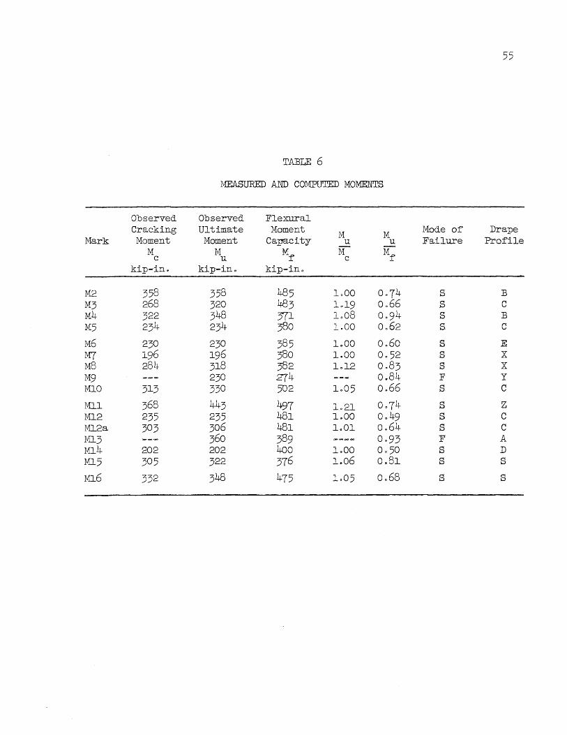
55
TABLE 6
MEASURED AND COMPUTED MOMENTS
Observed Observed Flexural Cracking Ultimate Moment M M Mode of Drape
Mark Moment Moment Capacity u u Failure Profile M M Mf' M Mf' c u c
kip-in. kip-in" kip-ina
M2 358 358 485 1000 0~74 s B M3 268 320 483 1 .. 19 0066 s C M4 322 348 371 1008 0094 s B M5 234 234 380 1.00 0062 S C
M6 230 230 385 1000 0 .. 60 s E M7 196 196 380 1.00 0.52 S X M8 284 318 382 1012 0.83 S X M9 230 274 0 .. 84 F Y MlO 313 330 502 1005 0.66 s C
Mll 368 443 497 1.21 0074 S z Ml2 235 235 481 1.00 0049 s C Ml2a 303 306 481 1001 0.64 S C Ml3 360 389 0·93 F A M14 202 202 400 1 .. 00 0050 s D Ml5 305 322 376 1~06 0.81 s S
M16 332 348 475 1005 0068 s s
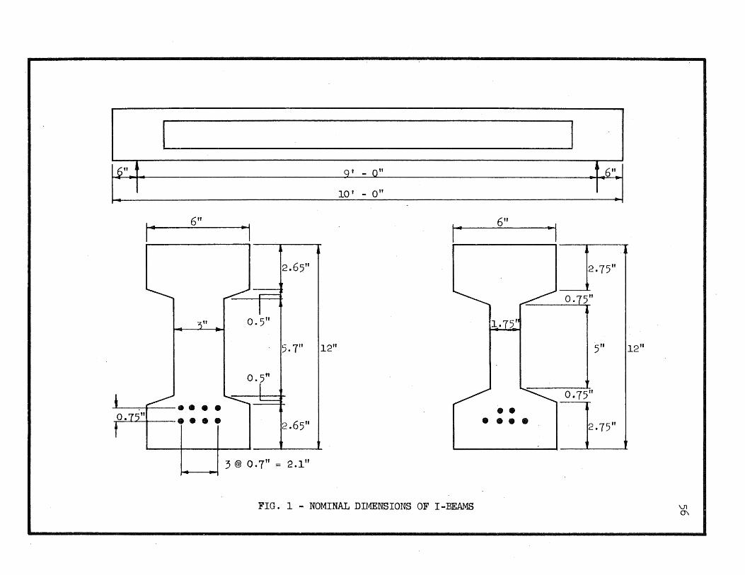
l)" A
6" I- -I • , ---w-----...
"-::::::F .. 3" 0.5" •
0.5" 1
~ .... --........~ tI····
2.65"
5.1" 112"
2.6511
3 @ 0.7" = 2.1"
g' - 0"
10 r _ 0"
--I , 6"
,.. 6" _,
I i--r-----r
2.75"
~ O.7~"
1.75" ~
5" 12"
~ 0·75"
•• •••• 2·75"
FIG. 1 - NOMINAL DIMENSIONS OF I-BEAMS \.n 0\

57
A
A-A
Profile C (Profiles A, B, D, E are similar)
B.....- ~ I
I I ~ ~
B-B f ,
B""-Profile S
C-+- ! I
I I I j
c-c t , c-+-
Pro:file X
n ....... ! ,
f--- I I ~
I I
D-D I I n-+-
Profile Z
FIG. 2 - DRAPE PROFILES

- I I I 1 I I I ,U I I
" I
I
0 500 ~ - - o c .-- -
I-- r"\ 0 C '-' 0 (
or! 400
f.f.l PI
"-
00 r"\ 0
0 0 ......
~ (b ........ O· ~
~O
~
-
~ ) 0 0
h
G-lH
Q) 300 H ;.j +' ~ ~
-~
........ '-" 0 -
"-./
.... "'{j -
V--r"\ '-"
0
I--IAI 0
~b
-----1- I
-
--ct-i 0
f.f.l ;.j 200 j to 0 ~
f :3z000 - = -r 12 -4 + _,000
10-
f r -
~ c
- I I I I ] I I
100
01000 2000 3000 4000 5000
Concrete Strength f~ - psi
FIG. :3 - COMPARISON 'OF MODULUS OF RUPTURE WITH CONCRETE STRENGTH ~

orl Ul ~
rf.l t.O OJ 1-i +' ro +' orl
~.
.......".." ...,
250 - --'-'~'-
If (/ 200
150 /
J / , 100
j
1III , ~ 50
lLL~ a o
~ ~~ I f~ 2 256,000 psi ~
~ ........ ~ r'---- -- 0.2% Offset Stress = 219,000 psi
6 0.196 in. Diam. E == 30 x 10 psi s 8 in. Gage Length
------ - --------
1 2 3 4 5 6 Unit Strain - Percent
FIG. 4 - STRESS -STRAIN RElATIONSHIP FOR IDT XI WIRE··
7
\.Jl \0

_It 2~)0
~ ~
~ f' ;::: 225 ksi s ....
(, ~ O.~ offset stress = 2.:;0 ksi
I 200
·rl til ~
15.0 ttl (f) (l) H
+> Ul
+> -rl
§ 100
I I t I I
I II
6 0.196 in diam. E = 29 x 10 psi 8 in. Gage Length s
/ I
510
I
3 4- C) 5 b 7 8 Unit Strain - Percent
FIG. 5 - STRESS-STRAIN RELATIONSHIP - - I..DT XII WIRE ~

-r-l U)
~
U) U) (l)
f..t +' m +' ~
§
50
40
.....
30
20
j
10
o
°
f~ =45,400 PSi~1
~,.
I
...."
I
I
I
E = 30,400,000 psi 0.161 in. Diameter s 8 in. Gage Length I
~-
0.5 1.0 1·5 2.0 2.5 3·0 3·5 4.0
Unit Strain - Percent
FIG. 6 - STRESS -STRAIN REIATIONSHIP FOR BLACK ANNEALED WIRE f!)

62
~ Midspan
I
I I I I I I
I
I I I
t I
3 @ 2 1/2'~ :-\ 10 @ 5" = 4 t - 2"
Type A Type B
/
'"
4"
1 '"
2 lL2"
·1 I I Eu ' , -
U ~
10"
Prestressing Wires _.
. ."\ ~ . ------------~---~ '-.--01
-k.9"l Type A Stirrups Type B Stirrup
FIG. 7 - STIRRUP DETAIIS

2 1 2"
3/8" Prestressing Hire
yields
Detail of Draping Saddle
A Draping Saddle in Beam M2
FIG. 8 - DRAPING SADDLES

Bearing Plate - Prestressing Frame -Pipe
C> M« 1110 <:> d
r> Concrete Beam
.t> <1 d Q
Pre8tre~sin~ Wires": OR'P, C'.t5. f'>.
Draping Saddle
stiffening Beam
Longitudinal Section
Prestressing Frame: Bearing Pla~e " ©J <1
3 ft Extra Heavy Pipe .
R: 12ft Channel Side Form c:u::~~___ Draping Saddle
Q'
Stiffening Beam: 18" by 3/8" Plate
1;1
10" by 1/2" Stiffening Plate
15" Channe 1
Transverse Section
FIG. 9 - CROSS-SECTIONS OF BEAM AND FORJ.'Jl
':;J,
o
~

Support wading Point
I I
I I
I I
I ... .. .. .. I I
.. .. .. '+ I
l' - -6" l' - 0" 4@ 3"=1' _dtr 6~ -yo -. ,.. - -
Strain Gages on Top of Beams Ml through M3
•• .. - .. I .. -I .-l' - 6" 9" 6" 3" 3" 9 11 ..
Strain Gages on Top of Beams M4 through Ml6
Midspan
l' - tt l' -
Strain Gages on Steel-Beams Ml through M8 (Beams M9 through Ml6 had gages at midspan only)
FIG. 10 - LOCATION OF STRAIN GAGES
Midspan
I 11
i I
6"
I
il I
6"

Columns: 8WF24
Cross Beams: 2-12[25 3/4" Bolts
Longitudinal Beam: 2-15C33.9
Hydraulic Jack
50 Kip Elastic Ring Dynamomete Distributing Beam
Dial Indicators
Anchors
East Elevation
Concrete Pier
/
Scale 3/8 in. 1 ft
FIG. 11 - DETAILS OF TESTING FRAME
:=
North Elevation u
0\ 0\

20
16
Ul A
..-f ~
12 rd ~
S rl oj
+> 0 E-f
8
J I.
·4
o
,.
V l1li-"" ---...
~ ~ Ml3
/ V
.V~
V ~
./ ~ II"""" -r--........
I/' ~ r-----. ~
/ ~ ~M9
I V V
I ( Mark Q
J M9 15 Ml3 22
I X Flexural Cracking
o Crushing
- - - - - -
Midspan Deflection - Inches
FIG. 12 - LOAD' DEFLECTION CURVES FOR BEAMS FAILING IN FLEXURE
Drape
y A
0\ -.;J

· South
Beam Ml5
.U
re 500 §
~
~ J A
!f\ _ 400 0 r-f
><
orf
J ~ tJ
~ t.)
re I (!) Q
orf r-I
Q oM ~ ~
of.:> tr.l ;00 (!)
of.:> a> ~ ()
tJ
I / Q H
C
I /'
}!f Q 0 t.)
re-a> 200 ~ til ~
~
orf
I ~ tJ cO B ~
./ u r-I VI V ~
/ ~.;---~ >< a>
~ ~// r-f
~ /'
~ .",./
~ ~ ~"
/
'/ " --100
p-I/
100 200 ;00 400
Measured Increase in Steel Strain x i05
FIG. 13 - RELATION BETWEEN CRITICAL CONCRETE AND STEEL STRAINS

(a) Beam M2 at ::"ailure
(b) Beam IDO at Failure
FIG. 14 - INITIATING CRACK DEVELOPING INTD A
~L~OR INCLINED Cru~CK

/1-3 s.~.
(a) Initiating Crack in Beam M3
(u) Beam M3 at Fa.ilure
FIG. 15 - DfITIATING CRACK ~"OLLO\-jED BY A MAJOR
INCLINED CRACK
70

I3eam M7 at Failurl!
FIG. 16 - }t!AJOR INCLINED CRACK ORIG INA'rING IN WEB

Initiating Crack
Support
Major Inclined Crack
20 e
• ... LIIIIIIIIl--- ,.",.--
",--fIIIIIII'" ",~
16
tVr
12
e
• /
r./ /"'
8
/ ,,-
<D 0
./ f"'1
~ -4
tt'l
o 2 4
• .... --~- •
x. l
x m
Load
x _____ m
~ '- .......
~.
X.~ l '\. .....
• ~" ;"
'"' ...., /' (j) ik_
~ 0
ex -m Major Inclined Crack
OXi - Initiating Crack
I I I
6 8 10
Angle of Drape - ~ - Degrees
72
FIG. 17 - LOCATION OF INITIATING CRACKS AND MAJOR INCLINED TENSION CRACKS

20
./
/ /
16
til Pl
oM ~
12 rd ~ 0 H
:1 r
J rl cd +' ~ 8
, J
I I
1 4
, o
0.2
~ -~ B4
~ ~
""""""" .-
/ V / fMl6 ,/ ~ . ..., M2 ..l1li
V~ / / ,.-~
/ / ~ M3
J r V / ~ ~
I / / ~
~A M12
T ~( V ,~ . yo ~ J
r-
J J J
( f I Mark Q Drape
I B4 36 -Ml6 45 -M2 42 B
I M3 32 C Ml2 45 C ,
j X' Flexural Cracking • Inclined Cracking , o Crushing
0.4 0.6 0.8 1.0 1.2 1.4 Midspan Deflection - Inches
FIG. 18 - LOAD DEFIECTION CURVES FOR BEAMS WITH ALL WIRES DRAPED
BEAMS WITH EIGHT WIRES
Failure
F s S S s
1.6
-1 \..N

20
16
CIl ~ ''; ~
12 rd ro S ,~ M m +l 0 8 8
4
o
::lo..
~~ - ~ ~
~4 ~ ~ ~ ,,- ~
V - "-/ ~ L ~ ,
Ml5 Ml3 ~
/ / /' V~
~ ./
/ / "/ ,
M5 M6
/ ~. A. .IJ ....
I' / ~/ / y ) ~ ,
~ Ml4
1~
J I I I f Mark Q Dra.pe
I ,. J
I , 0.2
j
I I ,
1 Ml3 27 A Ml5 34 -M4 27 B
f I I M5 35 c
'M6 26 E Ml4 22 - D
I , J X Flexural Cracking
~ r • Inclined Cracking
o Crushing
0.4 0.6 0.8 1.0 1.2 1.4 Midspan Deflection - Inches
FIG. 19 - LOAD DEFLECTION CURVES FOR BEAMS WITH ALL WIRES DRAPED
BEAMS WITH SIX WIRES
Fa.ilure
F S
s-c S S S
1.6
I
I
I
-l +-

---4 Prestr . esslng Wires
------------4.
(a) Beam Ml2 at Failure
These cracks from previous
---
"
(b) Beam M12a at Failure
(Numbers show Extent of Crack at Load Increments 2, 3, 4, 5 and 6)
FIG. 20 - TESTING PROCEDURE - - BEAMS M12 AND Ml2a -J \J1

20
16
ro A 'rl -~
12 rd oj
.3 M" ro +> 0 E-f
8 I / ,
4
J
o {
./ / 'M8
/ ".
I
/ ~
~ ,V \ I \ / I Mark ~ Drape
~- M7 34 X ,...., I
M8 34 X M7 .
X Flexural Cracking
• Incli'ned Cracking
-- L __ _._.-
0.2 0.4 0.6 0.8 1.0 1.2 1.4 Midspan Deflection - Inches
FIG. 21 - LOAD DEFLECTION CURVES FOR BEAMS WITH BOTH STRAIGHT AND DRAPED WIRES
Failure
s s
1.6
-3 0\

77
// / /
~
~ MlO
I { i' ,( , r-.
12
8 Mark Q Drape Failure
GX) 22 - F G19 42 - F MIl X) Z S-C MIO .29 C s-c
4 X Flexural Cracking .
• Inclined Cracking
0 Crushing I o
0.4 1.6 0.8 1.2 2.0
Midspan Deflection - Inches
FIG. 22 - LOAD DEFLECTION CURVES FOR BEAMS WITH WEB REINFORCEMENT

78
1.4
A • 1.2
-----~t ~
rO a:l 1.0 S bO Q
-r-I ~ CJ a:l ~ ()
0.8 Q 0
.r-4 Cf)
s::: a>
............ ~5'!> ~ •. - ~ .. ~ "- "-[)
......... ~~
~ r---,
... ~ ~~ " .....
v
"'" r" ~ -5% ............. [" ~
"" ..... ~ " ~I " 8 ~
rO a> s:::
0.6 -r-I r-i
e
CJ ~ H
rD rO OJ a> ~+' ;:J ::s Cf) Pi
0.4 a:l S (1) 0 ~ ()
0.2 eM Series - 3-in. Web
OM SerIes - 1 3/4-in. Web
o Average of Sozen's beams similar to M Series
I 0- 6 4 8 2 10
Angle of Drape - ~ - Degrees
FIG. 23 - EFFECT OF ANGLE OF DRllJ'E ON INCLINED TENSION CRACKING LOAD

79
1.4
1.2 ,,~
~!"' 0
bD Q
OM 1.0 ~ u m
H 0
Q 0
OM to Q Q)
0.8 8 ~ Q) Q
oM r-I U Q
H
~ 0.6 m
H ttl (l)
:~ -- ~
~ ... " [~ • '" '" ,
"-...... ........ II.. '" I'
~ ~ .
" " +10% "" .. 0 ,"" '" " ~" ." .~ i' '\ ~, " .. ~ '" -10%
~ ". "-H.Q ttlt:J) Q)
.Q r'd t:J) (l)
~ 0.4 ~ ;j Q)
~ z 0
0
'~~ I'
~, ." • ~ l'-~~a ....
,,~
. " 0.2
• M Series - 3-in. Web
o M Series - 1 3/4-in. Web
0 Average of Sozen's beams similar to M Series
I I , o
6 8 4 10 2
Angle of Drape - ~ - Degrees
FIG. 24 - EFFECT OF ANGLE OF DRAPE ON NET SHEAR AT INCLINED TENSION CRACKING

140
100
20
o
Inclined Cracking Load
-----+- Flexural Capacity
Ultimate Load
Inclined Cracking Load for Zero Drape
(from Sozen) Equation (2)
_----1--............ · ~--------~ .. --------
o 2
Load Causing Initiating Crack
4 6 Angle of Drape - ~ - Degrees
8 10
FIG. 25 - COMPARISON OF CRACKING LOADS AND ULTIMATE LOADS FOR VARIOUS DRAPE ANGLES
80

[
1r===============~1
~pre~~~::Sing I
Beam. M7 - - --1--1--
r- - - --.:-----t::=:::-~-=======-=-_ ~~=::;;;;;;;;;;;===::::::f---l=j t_ -- _ -- _ -- __ -=~--=-=---=--== I t
A I r 7 A
t
oM 250 to Pi
~ I ~
~ 0
..-I 200 +' CJ (l) U)
+' ~
to <V to to 150 <V ~ +' U)
<V r"""i -r! to ~ (J)
8 100 r"""i m p..
or! ()
~ oM H
p...
rd 50 <V ~ ;j
~ 0
0
o
These curves were computed for the observed inclined
tension cracking load for Beam M7 (p = 10.9k
). c
/ n I V/ i\
~~ I 1
All wires straight -
1/ V V V
/ / Draped Wires ~ " -;/ . (M?)
----~
\ l
24 Distance from Support - Inches
FIG. 26 - EFFECT OF DRAPING ON PRINCIPAL TENSILE STRESSES AT BOTTOM OF WEB

+P/2
82 I I I
I r~~- prestr~sslng . f !
Wires· Beam M7 _
==- ==--=-- t--_ . ---. -_. ---~-=--=--===~~--=-1
.,-f tI.l Pi·
I=Q I
I=Q
0 0
.,-f
+> u Q)
en +> m tI.l Q) tI.l tI.l Q) H
+> en (l)
,..-i .,-f tI.l 0 Q)
8 ,..-i to Pi
or-f u 0
or-f H ~
rod Q)
+> ~
~ 0 0
I I I
250
200
150
100
50
o
t These curves were computed for the observed inclined
tension cracking load for Beam M7 (p = 10.9k). c
"-~ ~
'" ...... All wires ............ ~
,,,- straight
~
~ " ~ ~
" ~ '\ Dra.ped Wires. . (M7) -'" ..... ~
'" ~\ '\ \ ~
12 24 Distance from Support - Inches
FIG. 27 - EFFECT OF DRAPING ON PRINCIPAL TENSILE STRESSES AT TOP OF WEB

83
1.4
(') 1.2 • rd
ro 0
....:I • bO ~
...-i
.!4 CJ
~~ • 0 .- .- .. 1- ..
ro 1.0 H - - -- r- ..
t.:> rd Q)
g til cd OJ ~ 0.8 0
\
-j-J
rd cd
S OJ
,-j-J
~ 0.6 ·rl -j-J r-f ~ • Beams without web
reinforcement rd OJ 0 Beams with web g reinforcement CJ)
ro 0.4 Q)
~
G-i 0
0 ..-i -j-J cd
p::;
0.2
2 6 8 10 Angle of Drape - ~ - Degrees
FIG. 28 - INCREASE IN LOAD AFTER INCLINED CRACKING
