effect of crgt cooling on modes of global vessel failure
TRANSCRIPT

EFFECT OF CRGT COOLING ON MODES OF GLOBAL VESSEL FAILURE OF A BWR LOWER HEAD
Walter Villanueva Division of Nuclear Power Safety
Royal Institute of Technology (KTH) Stockholm, Sweden
Chi-Thanh Tran Institute of Energy 6 Ton That Tung
Dong Da, Hanoi, Vietnam
Pavel Kudinov Division of Nuclear Power Safety
Royal Institute of Technology (KTH) Stockholm, Sweden
ABSTRACT An in-vessel stage of a severe core melt accident in a
Nordic type Boiling Water Reactor (BWR) is considered
wherein a decay-heated pool of corium melt inflicts thermal and
mechanical loads on the lower-head vessel wall. This process
induces creep leading to a mechanical failure of the reactor
vessel wall. The focus of this study is to investigate the effect of
Control Rod Guide Tube (CRGT) and top cooling on the modes
of global vessel failure of the lower head.
A coupled thermo-mechanical creep analysis of the lower
head is performed and cases with and without CRGT and top
cooling are compared. The debris bed heat-up, re-melting, melt
pool formation, and heat transfer are calculated using the Phase-
change Effective Convectivity Model and transient heat transfer
characteristics are provided for thermo-mechanical strength
calculations. The creep analysis is performed with the modified
time hardening creep model and both thermal and integral
mechanical loads on the reactor vessel wall are taken into
account. Known material properties of the reactor vessel as a
function of temperature, including the creep curves, are used as
an input data for the creep analysis.
It is found that a global vessel failure is imminent
regardless of activation of CRGT and top cooling. However, if
CRGT and top cooling is activated, the mode and timing of
failure is different compared to the case with no CRGT and top
cooling. More specifically, with CRGT and top cooling, there
are two modes of global vessel failure depending on the size of
the melt pool: (a) ‘ballooning’ of the vessel bottom for smaller
pools, and (b) ‘localized creep’ concentrated within the vicinity
of the top surface of the melt pool for larger pools. Without
CRGT and top cooling, only a ballooning mode of global vessel
failure is observed. Furthermore, a considerable delay (about
1.4 h) on the global vessel failure is observed for the roughly
30-ton debris case if CRGT and top cooling is implemented.
For a much larger pool (roughly 200-ton debris), no significant
delay on the global vessel failure is observed when CRGT and
top cooling is implemented, however, the liquid melt fraction
and melt superheat are considerably higher in non-cooling case.
INTRODUCTION The success of ex-vessel severe accident termination
and melt coolability in a deep pool of water located under the
reactor vessel of a Nordic Boiling Water Reactor (BWR) is
highly dependent on the melt ejection characteristics from the
lower head. It has been shown that melt fragmentation and
resulting characteristics of the debris bed ([1], [2], [3], [4]) as
well as coolability [5] are controlled by the mode of vessel
failure (rupture size and location, characteristic time of melt
ejection from the vessel, melt composition, amount of liquid
melt and its superheat, etc.). A non-coolable debris will dry out,
re-heat, and then re-melt, and consequently attack containment
base-mat, presenting a threat to containment integrity. In
addition, energetic molten fuel-coolant interaction, e.g., steam
explosion, in a deep reactor cavity is also sensitive to melt
discharge conditions [6] and is also known to create another
Proceedings of the 2012 20th International Conference on Nuclear Engineering collocated with the
ASME 2012 Power Conference ICONE20-POWER2012
July 30 - August 3, 2012, Anaheim, California, USA
ICONE20-POWER2012-54955
1 Copyright © 2012 by ASME

source of credible threat to containment integrity. Therefore, in
order to establish firmly that containment integrity can be
preserved, it is necessary to reduce uncertainties in the modes of
vessel failure.
Previously, a 2D coupled thermo-mechanical creep analysis has
been performed by Willschuetz et al. ([7], [8]) for the
FOREVER experiment (a scaled model of a pressurized water
reactor (PWR) vessel lower head) in order to investigate global
failure mode and predict failure time. A similar study by
Villanueva et al. [9] has focused on the analysis of the global
failure of a Nordic type BWR vessel wall under thermo-
mechanical load inflicted by a melt pool assuming that CRGT
and top cooling of the melt are available. It was found that the
amount of melt has an effect on the global vessel failure mode,
i.e., ballooning or localized creep. Another group of vessel
failure modes include failure of the local penetrations such as
nozzles of Instrumentation Guide Tube (IGT), CRGT, and the
pump. Previous work by Rempe et al. ([10], [11] addressed
different failure mechanisms in reactor pressure vessel (RPV)
lower heads for different PWR and BWR designs. They
performed structural analyses for the cases with metallic and
ceramic debris with the assumption that debris is unable to go
through the penetration. They found that vessel failure will not
occur in the case of metallic debris within 24 hours but vessel
failure is predicted in the case of ceramic debris by localized
thinning in the bottom of the vessel in less than 4 hours after
debris relocation. In the metallic case, heat from the 24 tons of
debris is primarily transferred to the coolant thus inflicting less
thermal load onto the vessel wall. While in the ceramic case
(120 tons), debris temperatures continue to rise because of
decay heat. A study by Ikonen [12] also addressed different
failure mechanisms in the lower head by a thermo-mechanical
analysis and supported the hypothesis that the pressure vessel
fails first at the welds of the IGT nozzles, but it is also pointed
out that there is an uncertainty in the interaction of the crust and
the nozzle that can cause a delay in failure. However, no CRGT
cooling was taken into account in all the above-mentioned
analyses and its potential as a severe accident mitigation
measure has not been investigated.
The goal of the present work is to investigate if CRGT cooling
(which also provides water for melt cooling from the top) can
have a significant effect on the modes of global vessel failure of
the lower head. The analysis is performed on a Nordic design
BWR lower head considering the cases with and without CRGT
cooling and debris top cooling at different melt pool depths.
The debris bed heat-up, re-melting, melt pool formation and
heat transfer are predicted with the Phase-change Effective
Convectivity Model (PECM) [13]. The PECM is implemented
on the platform of the Fluent code [14], and transient heat
transfer characteristics are provided for thermo-mechanical
strength calculations. The creep analysis is performed using the
commercial code ANSYS [15], taking into account both the
thermal and integral mechanical loads on the RPV. Material
properties of the reactor vessel are taken from Rempe et al.
[10]. The deformation of the vessel wall is assumed to have
negligible effect on the melt pool heat transfer, so only one way
coupling between PECM and ANSYS is employed.
In the next section, the modeling and simulation of the debris
bed and melt pool heat transfer is presented. Thermal transient
loads from these calculations are then used as boundary
conditions for the coupled thermo-mechanical creep analysis of
the vessel wall which is presented in Section II. This is followed
by concluding remarks in Section III.
I. Debris Bed and Melt Pool Heat Transfer
I.1. Heat Transfer Simulation Models
In the late phase of in-vessel accident progression, a debris bed
can form in the BWR lower plenum. If cooling is not adequate,
the debris bed heats-up and then re-melts. The debris bed heat-
up can be simulated by a conduction model. The re-melting
stage is simulated by the Effective Convectivity Model (ECM)
and the PECM [13].
Mechanical strength of the vessel wall depends on the thermal
loads imposed on its boundaries. In the present work the ECM
is used for prediction of transient thermal loads imposed on the
vessel wall from a decay-heated debris bed and melt pool
formed in the BWR lower head during a severe accident. The
ECM has been developed based on the concept of effective
convectivity proposed by Bui and Dinh [16]. The ECM is a
model for description of turbulent natural convection heat
transfer in an internally heated fluid volume. In the ECM
method, the convective terms of the energy conservation
equation are described using characteristic velocities; therefore
the need of solving Navier-Stokes equations is eliminated [13].
The characteristic velocities are determined using experimental
heat transfer correlations, namely the upward, sideward and
downward Steinberner-Reineke correlations [17]. The ECM is
implemented in the commercial code Fluent, to utilize all
advantages of a CFD commercial code solver such as the pre-
and post-processing.
To describe the crust formation phenomena, the ECM was
extended to the PECM. The ECM and PECM have been
validated against a set of experiments which cover a broad
spectrum of physical phenomena involved in melt pool
formation heat transfer, and wide range of Rayleigh number.
The ECM and PECM have been demonstrated as sufficiently
accurate and computationally efficient tools for 3D simulations
of melt pool formation heat transfer for a BWR accident
analysis [18].
2 Copyright © 2012 by ASME

I.2. Computational aspects
I.2.1. Material properties
A homogeneous melt pool is considered in this study. The melt
is assumed to be an oxidic corium with material properties
adopted from Theofanous et al. [19]. Scenarios of core damage,
relocation and quenching in the lower head water pool, which
can lead to formation of heterogeneous (oxidic and metallic
debris) or formation of stratified melt configuration (e.g. with
layers of metallic and oxidic melts) require further investigation
and are beyond the scope of this work.
I.2.2. Geometry and mesh
PECM simulations are performed for a 3D slice of BWR lower
plenum filled with decay-heated corium (see Figure 5 and
Figure 7 as references). The slice geometry is a segment of
BWR lower plenum that includes 8 CRGTs and bounded from
below by the vessel wall. It is assumed that the IGTs are melted
and plugged by corium melt during gradual re-melting of the
debris, and do not have an influence on melt pool heat transfer.
The CRGTs may be used as a flow path for water injection to
the reactor. In such a case, the CRGTs are protected from
thermal attack by cooling from inside. The water is assumed to
be ejected from the CRGTs providing a water layer atop of the
debris bed.
Two cases are considered in the present paper for both
scenarios with and without CRGT cooling; in the first case, the
maximum debris bed height is 0.7 m, and in the second case the
maximum bed height is 1.9 m. The slice is meshed with
hexahedron and tetrahedron 3D elements. To better capture the
dynamics of phase-change boundaries, Adaptive Mesh
Refinement (AMR) technique in Fluent is employed. The debris
bed computational domain is limited to about 1.5 million cells.
I.2.3. Boundary conditions
With CRGT cooling, isothermal boundary conditions (water
saturation temperature) are applied on the debris bed top and
inner CRGTs walls. For the other surfaces, Neumann boundary
conditions are applied. The external surface of the vessel wall is
covered with insulation so a small heat flux (20 W/m2) is
allowed.
For the cases without CRGT cooling, radiation heat transfer is
applied on the top debris bed surface with T∞ equal to
saturation temperature and the emissivity coefficient is set to
0.8. Zero heat-flux boundary conditions are applied on the
CRGT inner surfaces.
Initial temperature is set to 450 K and the solidus and liquidus
temperatures of debris are assumed to be 2750 K and 2770 K,
respectively. The solidus and liquidus temperatures of steel
(material of the vessel wall and CRGTs) are 1671 K and 1727 K
respectively [10].
I.3. PECM Calculations: With and Without
CRGT and Top Cooling
In this section, PECM calculations of 2 different debris bed
heights, H = 0.7 m and 1.9 m are presented. The debris bed
mass is considerably smaller in the 0.7 m case, around 30 tons,
compared to the 1.9 m case which is ~200 tons (considered the
maximum amount of melt that can get relocated to the lower
head). In both cases, the effect of CRGT and top cooling is
investigated. It is noted that some results for the case with
CRGT and top cooling have been presented in [20].
Figure 1. Temperature snapshot from PECM calculation for H =
0.7 m debris bed at t = 3.06 h, (a) with CRGT and Top cooling,
(b) without CRGT and Top cooling.
Snapshots of temperature profile is shown in Figure 1 for
H = 0.7 m at time t = 3.06 h comparing the cases with and
without CRGT and top cooling. For ease of discussion from
this point onwards, when we say ‘with cooling’ or just ‘cooling’
in a context, we meant ‘with CRGT and top cooling’. The
(a) with CRGT and Top cooling
(b) without CRGT and Top cooling
3 Copyright © 2012 by ASME

maximum temperature is a bit lower for the case with cooling,
which is 2708 K, while it is 2761 K for the case without
cooling.
Figure 2. Melt fraction snapshot from PECM calculation for
H = 0.7 m debris bed at t = 3.06 h, (a) with CRGT and Top
cooling, (b) without CRGT and Top cooling.
Snapshots of the melt fraction profile is shown in Figure 2 for
H = 0.7 m at time t = 3.06 h. The debris bed is still mostly solid
with the cooling case, which is only 5 % melt fraction located in
the bulk, compared to 18 % melt fraction with the non-cooling
case. In other words, the debris bed re-melts faster in the non-
cooling case as expected, which can also be seen in Figure 2b in
the regions between CRGTs.
Details of the melting of the CRGTs are shown in Figure 3 that
corresponds to H = 0.7 m. At about 1.94 h in Figure 3a, the
CRGTs start to melt with a direction from the center region of
the CRGT to its top and bottom, and from the center CRGT to
the periphery of the debris bed. At 2.22 h shown in Figure 3b,
the melting progresses in the same way and 5 out of the 7
CRGTs submerged in the debris bed has partially melted. Then
later at 2.78 h (Figure 3c), the melting follows the same trend
and 6 out of 7 of the CRGTs have larger melted factions than
previously.
The surface-averaged temperature profile of the bottom area of
the debris bed in contact with the vessel wall inner surface is
shown in Figure 4. The cases with and without cooling are
compared for H = 0.7 m at different times. At t = 3.06 h (Figure
4a) for the case with cooling, the average temperature is about
900 K and then decreases to about 468 K as it reaches the top.
Without cooling, the temperature is about 1200 K (with smaller
difference between minimum and maximum values compared to
the cooling case) and then decreases to about 706 K as it
reaches the top. At a later time t = 3.61 h, the temperature
profiles follow the same trend. With cooling, the temperature is
about 1000 K and decreases to about 475 K. Without cooling,
the temperature has smaller variations along the vessel wall
with a peak around 1400 K and decreases to about 757 K.
Figure 3. Melting of the CRGTs for H = 0.7 m debris bed at
times t = 1.94 h, 2.22 h, and 2.78 h (no CRGT and top cooling
provided).
(a) t = 1.94 h
(b) t = 2.22 h
(c) t = 2.78 h
(a) with CRGT and Top cooling
(b) without CRGT and Top cooling
4 Copyright © 2012 by ASME

Figure 4. Distribution of averaged temperature on the internal
vessel wall: Comparison of cases with and without CRGT and
Top cooling for H = 0.7 m debris bed at times (a) 3.06 h, and
(b) 3.61 h.
Snapshots of temperature and melt fraction for a larger debris
bed H = 1.9 m at t = 3.06 h are shown in Figure 5. With
cooling, the maximum temperature is 2762 K which is almost
equal to the non-cooling case at 2761 K. However, the melt
fraction in the cooling case is only 10 % compared to 29 % in
the non-cooling case. Parts of the CRGTs submerged in the
debris bed have mostly melted (more than 90 %) at this time. In
addition, the temperature and melt fraction in the periphery of
the debris bed is not affected whether there is cooling or not
since that region is not covered by CRGTs.
The surface-averaged temperature of the bottom area in contact
with the inner surface of the vessel wall is shown in Figure 6 for
H = 1.9 m. With cooling at t = 3.06 h, the average temperature
is about 900 K similar to the 0.7 m case but increases with a
peak around 1140 K in the region not covered by CRGTs, and
with a minimum temperature of 497 K at the surrounding tip of
the debris bed. Without cooling, the average temperature is
about 1200 K, even higher than the maximum temperature in
the region not covered by CRGTs, about 1147 K. At a later time
t = 3.61 h, the temperature follows the same trend. With
cooling, the temperature is about 1000 K and then increases
with a peak of 1296 K before it decreases to 513 K at the
surrounding tip. Without cooling, the temperature is about
1370 K then flattens to 1300 K in the region not penetrated by
CRGTs and finally decreases to 776 K at the tip.
In comparison, melting of the CRGTs starts at about 1.8 h in
both the 0.7 m and 1.9 m cases without cooling. But it is
considerably faster in the 1.9 m case in which about 90 % of the
CRGTs have melted after 2.6 h while it takes 1.4 h more in the
0.7 m case to reach 90 %.
II. Vessel Wall Thermo-mechanical Creep
Analysis
In this section, coupled thermo-mechanical creep analysis of the
pressure vessel wall is presented. The analysis takes into
account the debris bed heat transfer calculated by PECM that is
presented and discussed in the previous section.
II.1. Computational aspects
II.1.1. Material properties
The reactor pressure vessel that is considered is made of steel
SA533B1. The material properties that are all functions of
temperature such as density, elastic modulus (linear isotropic),
thermal conductivity (isotropic), specific heat, and coefficient
of thermal expansion are taken from Rempe et al. [10]. The
Poisson’s ratio is 0.3.
II.1.2. Axisymmetric model geometry and mesh
An axisymmetric model of a Nordic design BWR is considered
for the coupled thermo-mechanical creep analysis, see Figure 7.
Full transient analysis is implemented in ANSYS 13.0 [15]
where a strong structural-thermal coupling is supported. The 2D
geometry is meshed with 800 quadrilateral elements and 2731
nodes with an average edge length of 0.04. The element type
used is Quad Plane223 which is a 2D 8-node-coupled-field
(structural-thermal) solid.
(a) t = 3.06 h
(b) t = 3.61 h
5 Copyright © 2012 by ASME

Figure 5. Snapshot of PECM calculation for H = 1.9 m debris bed at t = 3.06 h. Temperature and Melt Fraction profiles, respectively,
(a)-(b) with CRGT and Top cooling, (c)-(d) without CRGT and Top cooling.
a) b)
Figure 6. Distribution of averaged temperature on the internal vessel wall: Comparison of cases with and without CRGT and Top
cooling for H = 1.9 m debris bed at times (a) 3.06 h, and (b) 3.61 h.
(a) (b)
(c) (d)
6 Copyright © 2012 by ASME

II.1.3. Boundary conditions
The thermal load from the debris bed is calculated using PECM
which is discussed in Section I. Other boundary conditions and
constraints are shown in Figure 7 which includes the weight
load, gravity, internal pressure (3 bars), and external pressure (1
bar). Debris bed of heights 0.7 m (that corresponds to a 30-ton
debris) and 1.9 m (that corresponds roughly to a maximum 200-
ton debris) are considered.
a)
b)
Figure 7. (a) 2D axisymmetric geometry and mesh with 850
quadrilateral elements and 2901 nodes, and (b) schematics of
mechanical load on the reactor vessel.
II.1.3. Creep model
For our analysis, a modified time hardening (primary) creep
model is chosen in ANSYS. Coefficients for the model are
generated using the experimental creep data for SA533B1 from
Rempe et al.[10]. Please see [9] for complete details along with
the validation test.
A yield or creep limit is not used in this study (see [9] for more
discussion). Instead we identify a range of percent strain that we
consider as reliably predicted by the model which is strains
within 20 %. This is partly based on the experimental creep data
and the creep model that we used. The time scale to reach 20 %
strain is one of our main interests since at this time the structure
is close to its mechanical failure.
II.2 Modes and Timing of Vessel Failure
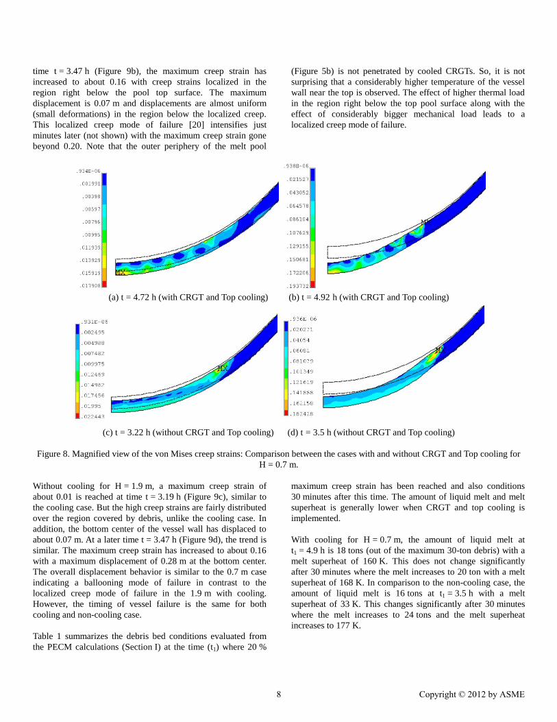
Magnified views of von Mises creep strains for H = 0.7 m are
shown in Figure 8. The progression of creep is slower in the
cooling case. With cooling at time t = 4.72 h, the maximum
strain is about 0.02 with high strains distributed over the region
covered by debris, and the bottom center of the vessel wall has
displaced to about 0.06 m (Figure 8a). Then at a later time
t = 4.92 h in Figure 8b, the maximum strain has increased to
0.19 and the bottom center also displaced further to 0.26 m and
displacements get smaller near the top of the pool which
indicates a ‘ballooning’ type of failure [20]. The rest of the
vessel has negligible displacements. Moreover, this ballooning
mode of failure intensifies just minutes later (not shown) with
the maximum creep strain gone beyond 0.20.
Without cooling for H = 0.7 m (see Figure 8c), a maximum
creep strain of about 0.02 is reached at an earlier time
t = 3.22 h, in comparison to the cooling case. The bottom center
has displaced to about 0.06 m and high creep strains are also
fairly distributed over the region covered by debris. A little bit
later at t = 3.5 h, the maximum creep strain has increased to
0.18 (see Figure 8d) with the bottom center being displaced to
about 0.22 m and displacements get smaller upon reaching the
top of the pool which also indicates a ballooning type of failure.
Thus, for a smaller debris bed H = 0.7 m the global vessel
failure is delayed by about 1.4 h if CRGT and top cooling is
implemented, but the failure is the same, a ballooning mode of
global vessel failure.
For a larger debris bed H = 1.9 m, von Mises creep strains are
shown in Figure 9. The progression of creep in time is the same
in both cooling and non-cooling cases but the displacement
behavior and distribution of strains are different. With cooling
at t = 3.19 h in Figure 9a, the maximum creep strain has reached
about 0.01 with a maximum displacement of 0.04 m. At a later
7 Copyright © 2012 by ASME
time t = 3.47 h (Figure 9b), the maximum creep strain has
increased to about 0.16 with creep strains localized in the
region right below the pool top surface. The maximum
displacement is 0.07 m and displacements are almost uniform
(small deformations) in the region below the localized creep.
This localized creep mode of failure [20] intensifies just
minutes later (not shown) with the maximum creep strain gone
beyond 0.20. Note that the outer periphery of the melt pool
(Figure 5b) is not penetrated by cooled CRGTs. So, it is not
surprising that a considerably higher temperature of the vessel
wall near the top is observed. The effect of higher thermal load
in the region right below the top pool surface along with the
effect of considerably bigger mechanical load leads to a
localized creep mode of failure.
(a) t = 4.72 h (with CRGT and Top cooling) (b) t = 4.92 h (with CRGT and Top cooling)
(c) t = 3.22 h (without CRGT and Top cooling) (d) t = 3.5 h (without CRGT and Top cooling)
Figure 8. Magnified view of the von Mises creep strains: Comparison between the cases with and without CRGT and Top cooling for
H = 0.7 m.
Without cooling for H = 1.9 m, a maximum creep strain of
about 0.01 is reached at time t = 3.19 h (Figure 9c), similar to
the cooling case. But the high creep strains are fairly distributed
over the region covered by debris, unlike the cooling case. In
addition, the bottom center of the vessel wall has displaced to
about 0.07 m. At a later time t = 3.47 h (Figure 9d), the trend is
similar. The maximum creep strain has increased to about 0.16
with a maximum displacement of 0.28 m at the bottom center.
The overall displacement behavior is similar to the 0.7 m case
indicating a ballooning mode of failure in contrast to the
localized creep mode of failure in the 1.9 m with cooling.
However, the timing of vessel failure is the same for both
cooling and non-cooling case.
Table 1 summarizes the debris bed conditions evaluated from
the PECM calculations (Section I) at the time (t1) where 20 %
maximum creep strain has been reached and also conditions
30 minutes after this time. The amount of liquid melt and melt
superheat is generally lower when CRGT and top cooling is
implemented.
With cooling for H = 0.7 m, the amount of liquid melt at
t1 = 4.9 h is 18 tons (out of the maximum 30-ton debris) with a
melt superheat of 160 K. This does not change significantly
after 30 minutes where the melt increases to 20 ton with a melt
superheat of 168 K. In comparison to the non-cooling case, the
amount of liquid melt is 16 tons at t1 = 3.5 h with a melt
superheat of 33 K. This changes significantly after 30 minutes
where the melt increases to 24 tons and the melt superheat
increases to 177 K.
8 Copyright © 2012 by ASME

For H = 1.9 m, the time to reach 20 % maximum creep strain is
t1 = 3.5 h in the cooling case (just a bit longer than the t1 = 3.4 h
in the non-cooling case). The amount of liquid melt at this time
is 68 tons (out of the maximum 200-ton debris) with a melt
superheat of only 23 K. After 30 minutes, the liquid melt
increases significantly to 112 tons along with the melt superheat
to 103 K. For the non-cooling case, the amount of melt at t1 is
144 tons, much higher than the cooling case. However, its
superheat is only 25 K similar to the cooling case. After
30 minutes, the liquid melt increases to 183 tons and the melt
superheat increases considerably to 278 K.
Without cooling, the welds of the CRGT nozzles melt at around
2.1 h (see Table 1) for both 0.7 m and 1.9 m cases. At this time,
the debris bed is still in its solid form.
(a) t = 3.19 h (with CRGT and Top cooling) (b) t = 3.47 h (with CRGT and Top cooling)
(c) t = 3.19 h (without CRGT and Top cooling) (d) t = 3.47 h (without CRGT and Top cooling)
Figure 9. von Mises creep strains: Comparison between the cases with and without CRGT and Top cooling for H = 1.9 m at times
t = 3.19 h and 3.47 h.
Table 1. Debris bed conditions at time t1 where 20 % maximum creep strain has been reached and then after 30 minutes.
H
[m]
Cooling Time at max ~20 %
creep strain, t1 [h]
Time of CRGT
nozzle weld
melting, t2 [h]
Amount of liquid melt
at t1 (and after 30 min)
[ton]
Average melt superheat at
t1 (and after 30 min) [K]
0.7 Yes 4.9 - 18 (20) 160 (168)
No 3.5 ~2.1 16 (24) 33 (177)
1.9 Yes 3.5 - 68 (112) 23 (103)
No 3.4 ~2.1 144 (183) 25 (278)
9 Copyright © 2012 by ASME

III. Conclusions
The effects of CRGT and top cooling of a debris bed on the
modes of global vessel failure of a BWR lower head have been
investigated. Two cases with different debris heights are
considered; H = 0.7 m corresponds to a roughly 30-ton debris
and H = 1.9 m corresponds to a roughly 200-ton debris
(assumed maximum inventory). It is found that in the 0.7 m
case, global vessel failure is delayed by about 1.4 h if CRGT
and top cooling is implemented.
In the 1.9 m case, timing of the global vessel failure is relatively
the same (with no significant delay) but the mode of failure is
different. With CRGT and top cooling, the mode of failure is a
localized creep while it is ballooning in the case without CRGT
and top cooling. The localized creep is concentrated within the
vicinity of the top surface of the melt pool because this region is
not penetrated by CRGTs. For the case without CRGT and top
cooling, the timing of global vessel failure is relatively the same
in both the 0.7 m and 1.9 m cases, specifically, 20 % creep
strain has been reached around 3.5 h. Amount and superheat of
liquid melt is considerably higher in non-cooling case for 1.9 m
bed.
Furthermore, melting of the CRGTs starts at about 1.8 h in both
the 0.7 m and 1.9 m cases without cooling. But it is
considerably faster in the 1.9 m case in which about 90 % of the
CRGTs have melted after 2.6 h while it takes 1.4 h more in the
0.7 m case to reach 90 %. However, the welds of the CRGT
nozzles melt around 2.1 h in both the 0.7 m and 1.9 m cases. At
this time, the debris bed is still in its solid form. Predicted
amounts of liquid melt and melt superheat can provide
important information for the consideration of ex-vessel
accident progression.
In the current analysis, the mechanical strength of the
considered 2D axisymmetric lower head has not been adjusted
to take into account the CRGT penetrations in the vessel wall.
In the next step of this work, full 3D modeling of global
deformation of the vessel taking into account penetrations will
be considered and compared to the current 2D analysis to
investigate in details the influences of the (i) reduction of the
overall mechanical strength of the lower head due to the
penetrations and (ii) reduction of the mechanical load due to
smaller weight of the wall with penetrations. Another extension
of the work is to investigate the effect of CRGT and top cooling
on modes of failure of the Instrumentation Guide Tube (IGT).
ACKNOWLEDGMENTS This work is supported by the Swedish Nuclear Radiation
Protection Authority (SSM), Swedish Power Companies,
European Commission (SARNET-2), Nordic Nuclear Safety
Program (NKS), and Swiss Federal Nuclear Safety Inspectorate
(ENSI) under the APRI- MSWI program at the Royal Institute
of Technology (KTH), Stockholm, Sweden.
REFERENCES [1] P. Kudinov, A. Karbojian, W. Ma, and T.-N. Dinh “The
DEFOR-S Experimental Study of Debris Formation
with Corium Simulant Materials”, Nuclear
Technology, 170(1), pp. 219-230 (2010).
[2] P. Kudinov, A. Karbojian, C.-T. Tran, and W.
Villanueva, “The DEFOR-A Experiment on Fraction
of Agglomerated Debris as a Function of Water Pool
Depth,” Proceedings of The 8th International Topical
Meeting on Nuclear Thermal-Hydraulics, Operation
and Safety (NUTHOS-8), Shanghai, China, October
10-14, N8P0296, (2010).
[3] P. Kudinov and M. Davydov, “Development and
Validation of the Approach to Prediction of Mass
Fraction of Agglomerated Debris,” Proceedings of The
8th International Topical Meeting on Nuclear
Thermal-Hydraulics, Operation and Safety (NUTHOS-
8), Shanghai, China, October 10-14, N8P0298, (2010).
[4] S. Yakush, P. Kudinov, and T.-N. Dinh, “Multiscale
Simulations of Self-organization Phenomena in the
Formation and Coolability of Corium Debris Bed,”
Proceedings The 13th International Topical Meeting
on Nuclear Reactor Thermal Hydraulics (NURETH-
13), September 27-October 2, 2009. Kanazawa City,
Ishikawa Prefecture, Japan, Paper N13P1143, (2009).
[5] S. Yakush and P. Kudinov, “Effects of Water Pool
Subcooling on the Debris Bed Spreading by Coolant
Flow,” Proceedings of ICAPP 2011, Nice, France,
May 2-5, 2011, Paper 11416, 2011.
[6] D. Magallon, K.H. Bang, S. Basu, G. Berthoud, M.
Bürger, M.L. Corradini, H. Jacobs, O. Melikhov, K.
Moriyama, M. Naitoh, J.H. Song, N. Suh, and T.G.
Theofanous, “FCI phenomena uncertainties impacting
predictability of dynamic loading of reactor structures
(SERENA programme),” Proceedings Workshop on
Evaluation of Uncertainties in Relation to Severe
Accidents and Level 2 Probabilistic Safety Analysis,
Hotel Aquabella, Aix-en-Provence, France, November
7–9 (2005).
[7] H.-G. Willschuetz, E. Altstadt, B. R. Sehgal, and F.-P.
Weiss, “Coupled thermal structural analysis of LWR
vessel creep failure experiments”, Nucl. Eng. Des.,
208, pp. 265-282 (2001) .
[8] H.-G. Willschuetz, E. Altstadt, B. R. Sehgal, and F.-P.
Weiss, “Recursively coupled thermal and mechanical
FEM-analysis of lower plenum creep failure
experiments”, Annals of Nuclear Energy, 33, pp. 126-
148 (2006).
[9] W. Villanueva, C.-T. Tran, and P. Kudinov, “Coupled
Thermo-Mechanical Creep Analysis for Boiling Water
Reactor Pressure Vessel Wall Lower Head,”
10 Copyright © 2012 by ASME

Proceedings of The 8th International Topical Meeting
on Nuclear Thermal-Hydraulics, Operation and Safety
(NUTHOS-8), Shanghai, China, October 10-14,
N8P0248, (2010). Nucl. Eng. Des., in press.
[10] J. L. Rempe, S. A. Chavez, G. L. Thinnes, C. M.
Allison, G. E. Korth, R. J. Witt, J. J. Sienicki, S. K.
Wang, L. A. Stickler, C. H. Heath, and S. D. Snow,
Light Water Reactor Lower Head Failure, Report
NUREG/CR-5642, Idaho Falls (1993).
[11] S. A. Chavez, and J. L., “Finite element analyses of a
BWR vessel and penetration under severe accident
conditions”, Nucl. Eng. Des., 148, pp. 413-435 (1994)
.
[12] K. Ikonen, “Mechanical analysis of Olkiluoto RPV
bottom in core melting accident”, VTT Research
Report, PRO1/7017/04, 2004.
[13] C.-T. Tran, T.-N. Dinh, “The effective convectivity
model for simulation of melt pool heat transfer in a
light water reactor pressure vessel lower head. Part I:
Physical processes, modeling and model
implementation”, Progress in Nuclear Energy, 51, pp.
849-859 (2009).
[14] http://www.fluent.com/.
[15] http://ansys.com/.
[16] V. A. Bui and T.-N. Dinh, “Modeling of heat transfer in
heated-generating liquid pools by an effective
diffusivity-convectivity approach”, Proceedings of 2nd
European Thermal-Sciences Conference, Rome, Italy,
1365-1372 (1996).
[17] U. Steinberner and H. H. Reineke, “Turbulent
buoyancy convection heat transfer with internal heat
sources”, Proceedings of the 6th International Heat
Transfer Conference, Toronto, Canada, 2, 305-310
(1978).
[18] C.-T. Tran and T.-N. Dinh, “The effective convectivity
model for simulation of melt pool heat transfer in a
light water reactor lower head. Part II: Model
assessment and application”, J. Progress in Nuclear
Energy, 51, 860-871 (2009).
[19] T. G. Theofanous, C. Liu, S. Additon, S. Angelini, O.
Kymäläinen, and T. Salmassi, In-vessel coolability and
retention of core melt, DOE/ID-10460, Vol. 1-2, US
DOE, October (1996).
[20] W. Villanueva, C.T. Tran, P. Kudinov, "Assessment
with Coupled Thermo-Mechanical Creep Analysis of
Combined CRGT and External Vessel Cooling
Efficiency for a BWR", NURETH-14, Toronto,
Canada, September 25-30, 2011.
11 Copyright © 2012 by ASME