eems atmospheric emissions calculations v1 · pdf fileeems-atmospheric emissions calculations...
TRANSCRIPT
EEMS
Atmospheric Emissions Calculations
11th November 2008 Updated for private and public area of EEMS replica of Root-5 version 1.10 Page 2
EEMS-Atmospheric Emissions Calculations (Issue 1.810a)
CONTENTS
CONTENTS 2
1 INTRODUCTION 4
1.1 The Operator Community 4
1.2 EEMS Development and Support 5
1.3 Document Conventions 5
1.4 References 6
1.5 Acknowledgements 6
2 REPORTING REQUIREMENTS 7
2.1 Emission Gases 7
2.2 Emission Types and Sources 8
2.3 Halogenated Compounds 9
3 APPROACH 10
3.1 Monitoring Systems 10
3.2 Emission Factors 10
4 SCIENTIFIC BACKGROUND 13
4.1 The Ideal Gas Law 13
4.2 Mole (mol) 13
4.3 Avogadro’s Constant (NA) 14
4.4 Absolute Temperature 14
4.5 Atomic vs Molecular Weights 14
5 STANDARD CONDITIONS 16
5.1 Definition 16
5.2 API Standard Conditions 17
5.3 Standard Molar Volume 17
5.4 Standard Densities 17
5.5 Converting Non-Standard Volume to Mass 18
5.6 Normal Conditions 18
6 COMPONENT WEIGHTS 20
7 EMISSION CALCULATION AND FACTORS 22
7.1 Combustion Emissions 23
7.2 Non-Combustibles 26
7.3 Direct 28
7.4 Sulphur Content 28
7.5 Turbine NOX 29

11th November 2008 Updated for private and public area of EEMS replica of Root-5 version 1.10 Page 3
EEMS-Atmospheric Emissions Calculations (Issue 1.810a)
8 COMBUSTION PROCESSES 31
8.1 Gas and Liquid Fuel Turbines 31
8.2 Gas Consumption – Plant Operations 31
8.3 Diesel Consumption – Plant Operations 33
8.4 Fuel Oil Consumption – Plant Operations 34
8.5 Gas Flaring 35
9 DIRECT EMISSION 37
9.1 Gas Venting 37
9.2 Direct Process Emissions 38
9.3 Oil Loading 38
9.4 Storage Tanks 39
9.5 Fugitive Emissions 41
9.6 Halogenated Compounds 43
10 DRILLING 44
10.1 Well Testing 44
10.2 Diesel Consumption 45
APPENDIX A –CONVERSION CONSTANTS 47
APPENDIX B – ATOMIC WEIGHTS 48
APPENDIX C – MOLECULAR WEIGHTS 49
APPENDIX E – UKOOA TURBINE REFERENCES 50
APPENDIX F – HALOGENATED COMPOUNDS CO2 EQUIVALENTS 52
11th November 2008 Updated for private and public area of EEMS replica of Root-5 version 1.10 Page 4
EEMS-Atmospheric Emissions Calculations (Issue 1.810a)
1 INTRODUCTION
The aim of this document is to provide a clear specification of the atmospheric emissions calculations performed by the new, internet-based Environmental Emissions Monitoring System (EEMS). For 2004, methodologies and emission factors remain unchanged to provide a smooth transition between IT systems. However, UKOOA has participated in an International Petroleum Industry Environmental Conservation Association (IPIECA) update of emission inventory systems for the oil and gas industry. The results have been published by the American Petroleum Institute (API) and will be reflected in future EEMS updates.
1.1 The Operator Community
This guide sets out to inform the operator community of the exact nature of the calculations performed by EEMS on their behalf. It builds on previous work detailed in UKOOA workgroup papers describing the system and in the user guidance issued by Learn-IT.
Currently, Excel spreadsheets are used to both calculate emissions and to input data to a central Oracle server EEMS, which repeats the calculations. The disadvantage, in terms of data assurance and quality control, is that emission calculations occur in two places using two different technologies. Whilst checks have been made and documented by Learn-IT and UKOOA to ensure consistency, no external analysis has been undertaken to verify this.
Many operators perform these calculations themselves for internal purposes, often using in-house variants of the original EEMS spreadsheet. There is a potential for discrepancies in company systems as EEMS has been periodically updated and not all company systems have followed.
The new system will provide UKOOA and the DTI with a higher level of assurance in terms of data calculations and consistency within the EEMS system. Users will no longer have local calculation systems available except that the results of central EEMS calculations will be available to them directly from the internet-based system.

11th November 2008 Updated for private and public area of EEMS replica of Root-5 version 1.10 Page 5
EEMS-Atmospheric Emissions Calculations (Issue 1.810a)
1.2 EEMS Development and Support
The development team of the new EEMS computer system require an unambiguous and clear specification of the atmospheric calculations. The new system will perform these calculations in one place, and one place only, the central EEMS Oracle server. This removes the obvious risks associated with the dual maintenance of code performing complex and highly sensitive calculations. This document hopes to provide a basis for the ongoing support of these calculations as the system evolves in response to changing regulatory requirements.
1.3 Document Conventions
The conventions used in this document will adhere to those recommended by the National Institute for Standards and Technology1 (NIST) and the International Standards Organisation2 (ISO). A full discussion is out of the scope of this document but a brief summary is included.
Système International (SI) Units of measure will be introduced using the SI approved unit name followed by the SI approved symbol for the unit in brackets e.g. kelvin (K). For the remainder of the document the symbol will then be used.
Combinations of units will be separated by a period “· “ representing the product of the combined units. Quotients will be represented by negative exponents in preference to the division operator “/” e.g. m· s-1 as opposed to m/s.
Values are quoted with the mantissa between +999 and –999 with exponents in multiples of three e.g. 101.325 x 10³ Pa. If the number of significant figures results in more than 3 decimal places of precision, numbers will be given in groups of three with a single space, not a comma, between each group.
Non-SI units will be introduced and quoted in the same way. The names and symbols used are those in most common usage and will avoid ambiguity e.g. avoirdupois pound (lb) and troy pound (lb(tr)), international foot (ft) and US Survey Foot (ft(US Survey)).
1 Guide for the Use of the International System of Units (SI), The National Inst. Standards and Tech., Special Publication 811. Washington D.C., USA: US Govt. Printing Office, 1995 2 Quantities and Units, ISO Standards Handbook, 3rd ed. Geneva, Switzerland: International Organisation for Standardisation, 1993
11th November 2008 Updated for private and public area of EEMS replica of Root-5 version 1.10 Page 6
EEMS-Atmospheric Emissions Calculations (Issue 1.810a)
1.4 References
This document’s main aim is to provide a clear specification of the atmospheric calculations for the operator community and the new EEMS development and support teams. Emission factors and calculation methodologies are approved by the UKOOA Atmospheric Emission Work Group based upon UK studies, Oil and Gas Producers Association, American Petroleum Institute and the US Environmental Protection Agency. In 1998 the system was the subject of an external review by specialists at AEA Technology.
In recognition of the variations between turbine emissions and the importance to UKOOA, particularly of NOx emissions, a further review was undertaken by Advantica in 2002.
Detailed references to the origin of the EEMS methodology are found in the documents listed below.
1. EEMS Atmospheric Emissions submission spreadsheet (Revision 4 – 4th December 2002)
2. Guidelines for the Compilation of an Atmospheric Emissions Inventory – (Revision 4 – 4th December 2002)
3. Atmospheric Emissions Inventory: Revised Guidelines 1998 AEAT-3886.
4. Offshore Turbines – Predictive Emission Monitoring System. Advantica Technology 2002.
1.5 Acknowledgements
The author is indebted to Dr Peter Russell, Senior Environmental Consultant of Granherne Limited for reviewing this document and clarifying a number of important issues. In particular for additional references provided, clarification on calculation and default emission factor origins and their application (Issue 1.7).

11th November 2008 Updated for private and public area of EEMS replica of Root-5 version 1.10 Page 7
EEMS-Atmospheric Emissions Calculations (Issue 1.810a)
2 REPORTING REQUIREMENTS
Before embarking on a detailed description of the EEMS atmospheric calculations it is worth considering their main purpose and general context.
Legislation
The UK government is a signatory to several international protocols and treaties with obligations to report the emission of environmentally sensitive gases. Most notably the United Nations Framework Convention and Kyoto Protocol, entered into force on 21st March 1994. These international agreements have associated national legislation e.g. Offshore Combustion Installations (Prevention and Control of Pollution) Regulations 2001.
Under current legislation operators must submit annual emissions data for each installation and terminal where the energy input to all qualifying combustion plant, including spares, exceeds 50 Megawatt of thermal input (MWth). Energy inputs are to be aggregated at nameplate maximum possible continuous rating at site conditions.
2.1 Emission Gases
Annual emission data for gases with environmental significance are required by current legislation (Table 2.1 and 2.3).
Table 2.1: The Emission Gases
Emission Gas Symbol
Carbon Dioxide CO2
Nitrogen Oxides NOX
Nitrous Oxide N2O
Sulphur Dioxide SO2
Carbon Monoxide CO
Methane CH4
Volatile Organic Compounds
VOC
For the remainder of this document this group of gases will be referred to collectively as the emission gases.
11th November 2008 Updated for private and public area of EEMS replica of Root-5 version 1.10 Page 8
EEMS-Atmospheric Emissions Calculations (Issue 1.810a)
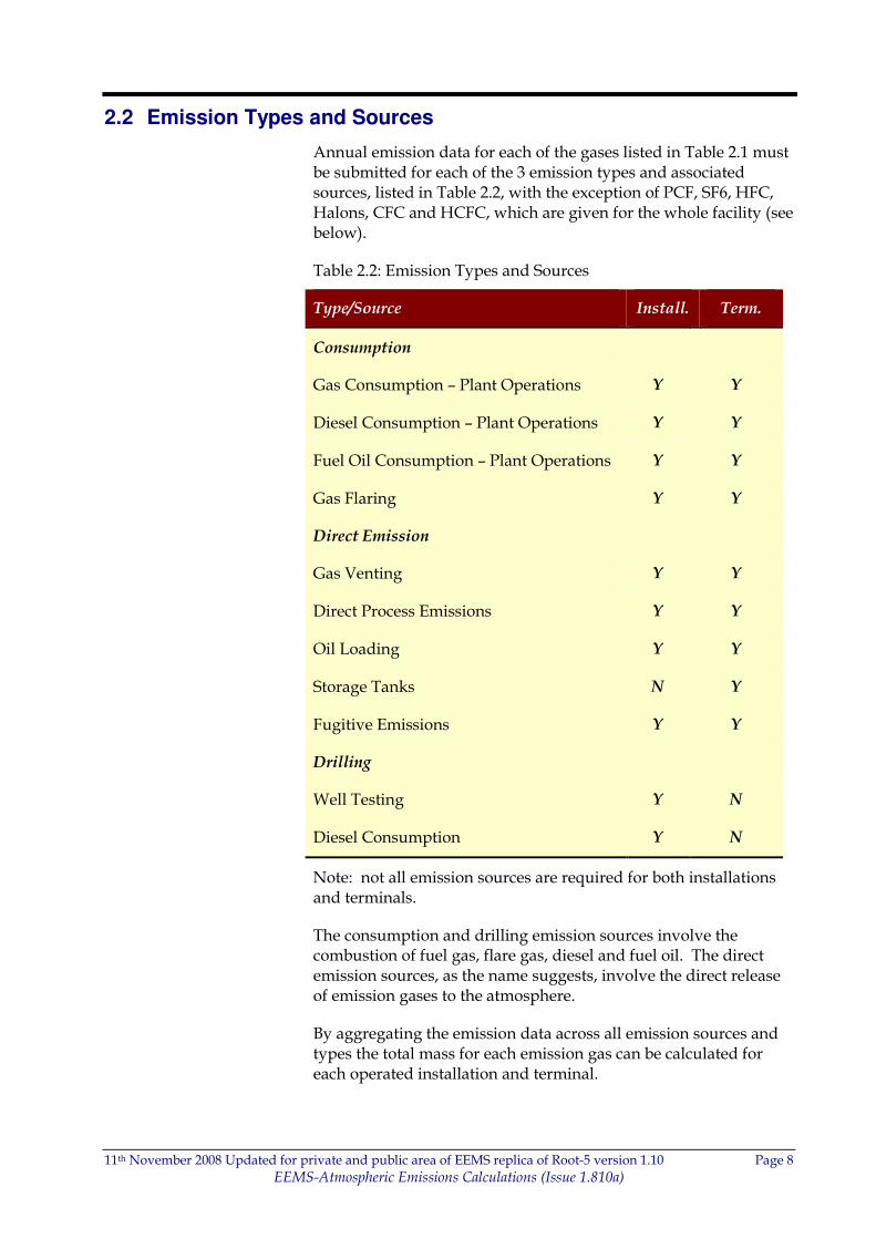
2.2 Emission Types and Sources
Annual emission data for each of the gases listed in Table 2.1 must be submitted for each of the 3 emission types and associated sources, listed in Table 2.2, with the exception of PCF, SF6, HFC, Halons, CFC and HCFC, which are given for the whole facility (see below).
Table 2.2: Emission Types and Sources
Type/Source Install. Term.
Consumption
Gas Consumption – Plant Operations Y Y
Diesel Consumption – Plant Operations Y Y
Fuel Oil Consumption – Plant Operations Y Y
Gas Flaring Y Y
Direct Emission
Gas Venting Y Y
Direct Process Emissions Y Y
Oil Loading Y Y
Storage Tanks N Y
Fugitive Emissions Y Y
Drilling
Well Testing Y N
Diesel Consumption Y N
Note: not all emission sources are required for both installations and terminals.
The consumption and drilling emission sources involve the combustion of fuel gas, flare gas, diesel and fuel oil. The direct emission sources, as the name suggests, involve the direct release of emission gases to the atmosphere.
By aggregating the emission data across all emission sources and types the total mass for each emission gas can be calculated for each operated installation and terminal.
11th November 2008 Updated for private and public area of EEMS replica of Root-5 version 1.10 Page 9
EEMS-Atmospheric Emissions Calculations (Issue 1.810a)
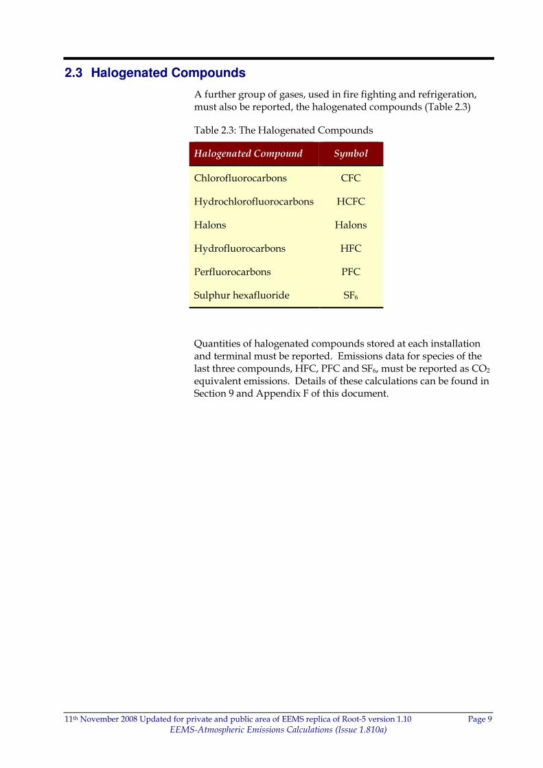
2.3 Halogenated Compounds
A further group of gases, used in fire fighting and refrigeration, must also be reported, the halogenated compounds (Table 2.3)
Table 2.3: The Halogenated Compounds
Halogenated Compound Symbol
Chlorofluorocarbons CFC
Hydrochlorofluorocarbons HCFC
Halons Halons
Hydrofluorocarbons HFC
Perfluorocarbons PFC
Sulphur hexafluoride SF6
Quantities of halogenated compounds stored at each installation and terminal must be reported. Emissions data for species of the last three compounds, HFC, PFC and SF6, must be reported as CO2 equivalent emissions. Details of these calculations can be found in Section 9 and Appendix F of this document.
11th November 2008 Updated for private and public area of EEMS replica of Root-5 version 1.10 Page 10
EEMS-Atmospheric Emissions Calculations (Issue 1.810a)
3 APPROACH
The original EEMS system used a number of Tiers, each requiring more detailed input, or activity data on which to base emission calculations. The direct measurement or monitoring of emission gases is rare offshore, but increasingly common for larger sources at onshore terminals. For most sources only activity data, such as fuel consumption or the rate of a process activity, are available.
Each emission source has a calculation methodology and emission factors available, discussed in subsequent sections. Details of the approach, assumptions and defaults used are given. The following outlines the overall approach.
3.1 Monitoring Systems
Emissions monitoring systems may be available onshore for major sources but are rarely used offshore. Where emissions monitoring systems are available, these may operate as part of an environmental management system, often with external certification or verification.
3.2 Emission Factors
Many operators do not have verified monitoring systems, or if they do, they do not furnish emission gas data for all emission sources.
The calculation of emissions where direct monitoring results are not available involves the use of an activity factor, such as fuel consumption or flow to flare/vent, and an emission factor for each source (s) and emission gas (i). By multiplying the activity factor (A) by the emission factor (E), the masses of each emission gas can be calculated.
M(is) = E(is) x A(s) 3.1
Where
• M(is) is the emitted mass of a particular emission gas (i) for a given source (s)
• A(s) is the source (s) activity factor
• E(is) is the emission factor for the emission gas (i) relevant to the emission source (s)
There are two basic types of emission factors used in the EEMS atmospherics calculations: default and calculated
11th November 2008 Updated for private and public area of EEMS replica of Root-5 version 1.10 Page 11
EEMS-Atmospheric Emissions Calculations (Issue 1.810a)
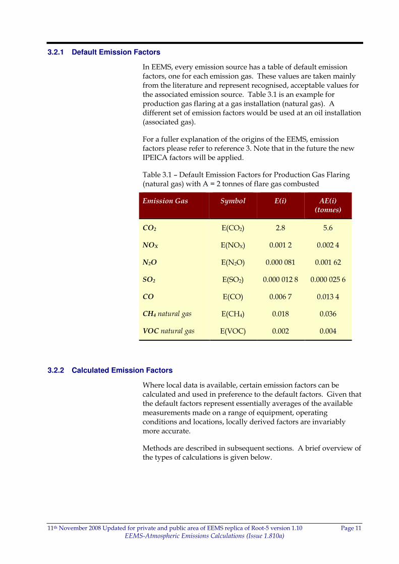
3.2.1 Default Emission Factors
In EEMS, every emission source has a table of default emission factors, one for each emission gas. These values are taken mainly from the literature and represent recognised, acceptable values for the associated emission source. Table 3.1 is an example for production gas flaring at a gas installation (natural gas). A different set of emission factors would be used at an oil installation (associated gas).
For a fuller explanation of the origins of the EEMS, emission factors please refer to reference 3. Note that in the future the new IPEICA factors will be applied.
Table 3.1 – Default Emission Factors for Production Gas Flaring (natural gas) with A = 2 tonnes of flare gas combusted
Emission Gas Symbol E(i) AE(i) (tonnes)
CO2 E(CO2) 2.8 5.6
NOX E(NOX) 0.001 2 0.002 4
N2O E(N2O) 0.000 081 0.001 62
SO2 E(SO2) 0.000 012 8 0.000 025 6
CO E(CO) 0.006 7 0.013 4
CH4 natural gas E(CH4) 0.018 0.036
VOC natural gas E(VOC) 0.002 0.004
3.2.2 Calculated Emission Factors
Where local data is available, certain emission factors can be calculated and used in preference to the default factors. Given that the default factors represent essentially averages of the available measurements made on a range of equipment, operating conditions and locations, locally derived factors are invariably more accurate.
Methods are described in subsequent sections. A brief overview of the types of calculations is given below.
11th November 2008 Updated for private and public area of EEMS replica of Root-5 version 1.10 Page 12
EEMS-Atmospheric Emissions Calculations (Issue 1.810a)
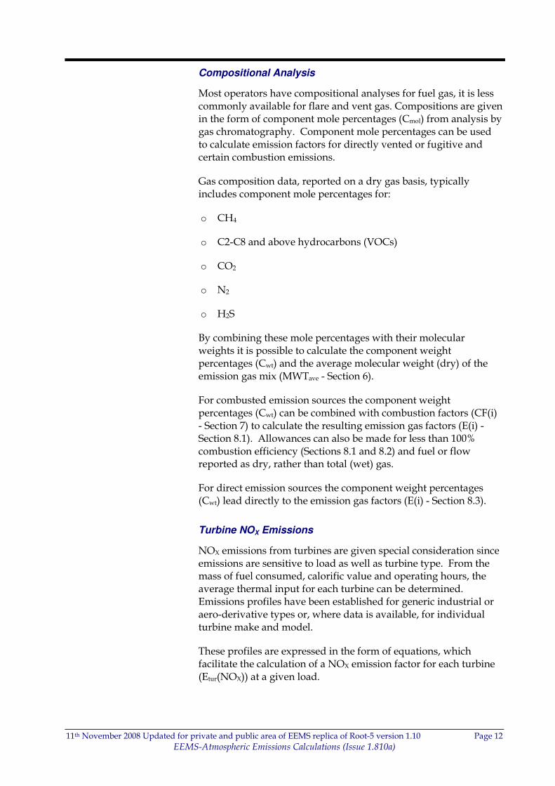
Compositional Analysis
Most operators have compositional analyses for fuel gas, it is less commonly available for flare and vent gas. Compositions are given in the form of component mole percentages (Cmol) from analysis by gas chromatography. Component mole percentages can be used to calculate emission factors for directly vented or fugitive and certain combustion emissions.
Gas composition data, reported on a dry gas basis, typically includes component mole percentages for:
o CH4
o C2-C8 and above hydrocarbons (VOCs)
o CO2
o N2
o H2S
By combining these mole percentages with their molecular weights it is possible to calculate the component weight percentages (Cwt) and the average molecular weight (dry) of the emission gas mix (MWTave - Section 6).
For combusted emission sources the component weight percentages (Cwt) can be combined with combustion factors (CF(i) - Section 7) to calculate the resulting emission gas factors (E(i) - Section 8.1). Allowances can also be made for less than 100% combustion efficiency (Sections 8.1 and 8.2) and fuel or flow reported as dry, rather than total (wet) gas.
For direct emission sources the component weight percentages (Cwt) lead directly to the emission gas factors (E(i) - Section 8.3).
Turbine NOX Emissions
NOX emissions from turbines are given special consideration since emissions are sensitive to load as well as turbine type. From the mass of fuel consumed, calorific value and operating hours, the average thermal input for each turbine can be determined. Emissions profiles have been established for generic industrial or aero-derivative types or, where data is available, for individual turbine make and model.
These profiles are expressed in the form of equations, which facilitate the calculation of a NOX emission factor for each turbine (Etur(NOX)) at a given load.
11th November 2008 Updated for private and public area of EEMS replica of Root-5 version 1.10 Page 13
EEMS-Atmospheric Emissions Calculations (Issue 1.810a)
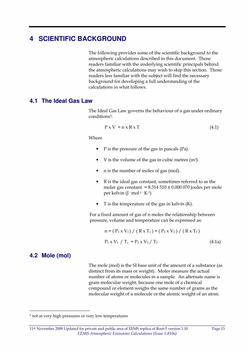
4 SCIENTIFIC BACKGROUND
The following provides some of the scientific background to the atmospheric calculations described in this document. Those readers familiar with the underlying scientific principals behind the atmospheric calculations may wish to skip this section. Those readers less familiar with the subject will find the necessary background for developing a full understanding of the calculations in what follows.
4.1 The Ideal Gas Law
The Ideal Gas Law governs the behaviour of a gas under ordinary conditions3:
P x V = n x R x T (4.1)
Where
• P is the pressure of the gas in pascals (Pa).
• V is the volume of the gas in cubic metres (m3).
• n is the number of moles of gas (mol).
• R is the ideal gas constant, sometimes referred to as the molar gas constant = 8.314 510 ± 0.000 070 joules per mole per kelvin (J· mol-1· K-1)
• T is the temperature of the gas in kelvin (K).
For a fixed amount of gas of n moles the relationship between pressure, volume and temperature can be expressed as:
n = ( P1 x V1 ) / ( R x T1 ) = ( P2 x V2 ) / ( R x T2 )
P1 x V1 / T1 = P2 x V2 / T2 (4.1a)
4.2 Mole (mol)
The mole (mol) is the SI base unit of the amount of a substance (as distinct from its mass or weight). Moles measure the actual number of atoms or molecules in a sample. An alternate name is gram molecular weight, because one mole of a chemical compound or element weighs the same number of grams as the molecular weight of a molecule or the atomic weight of an atom.
3 not at very high pressures or very low temperatures
11th November 2008 Updated for private and public area of EEMS replica of Root-5 version 1.10 Page 14
EEMS-Atmospheric Emissions Calculations (Issue 1.810a)
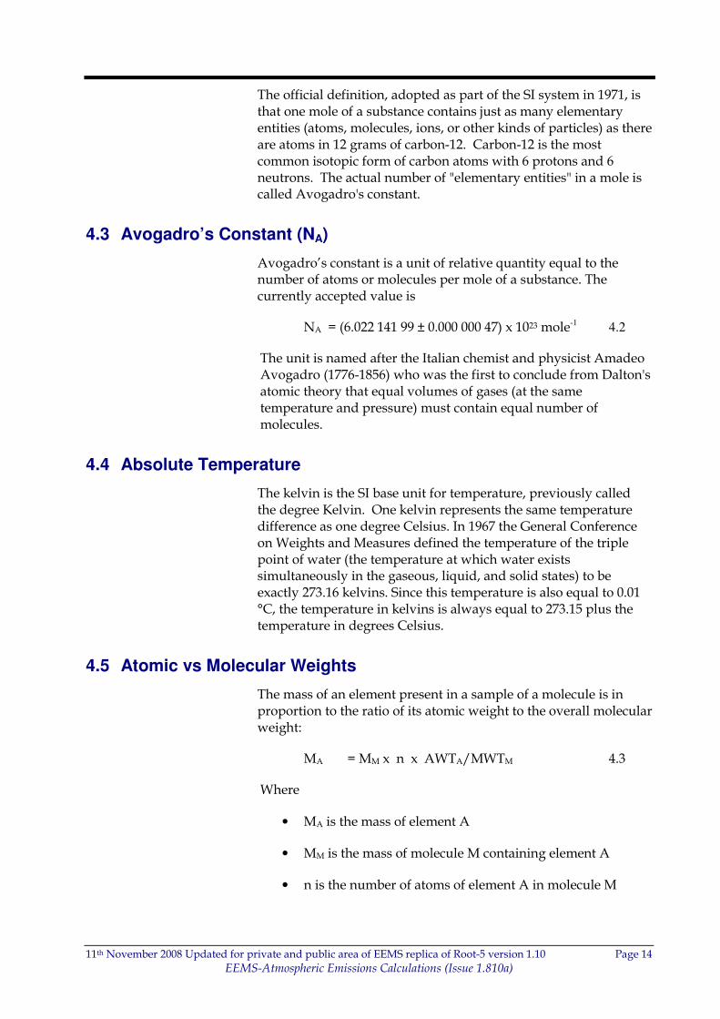
The official definition, adopted as part of the SI system in 1971, is that one mole of a substance contains just as many elementary entities (atoms, molecules, ions, or other kinds of particles) as there are atoms in 12 grams of carbon-12. Carbon-12 is the most common isotopic form of carbon atoms with 6 protons and 6 neutrons. The actual number of "elementary entities" in a mole is called Avogadro's constant.
4.3 Avogadro’s Constant (NA)
Avogadro’s constant is a unit of relative quantity equal to the number of atoms or molecules per mole of a substance. The currently accepted value is
NA = (6.022 141 99 ± 0.000 000 47) x 1023 mole-1 4.2
The unit is named after the Italian chemist and physicist Amadeo Avogadro (1776-1856) who was the first to conclude from Dalton's atomic theory that equal volumes of gases (at the same temperature and pressure) must contain equal number of molecules.
4.4 Absolute Temperature
The kelvin is the SI base unit for temperature, previously called the degree Kelvin. One kelvin represents the same temperature difference as one degree Celsius. In 1967 the General Conference on Weights and Measures defined the temperature of the triple point of water (the temperature at which water exists simultaneously in the gaseous, liquid, and solid states) to be exactly 273.16 kelvins. Since this temperature is also equal to 0.01 °C, the temperature in kelvins is always equal to 273.15 plus the temperature in degrees Celsius.
4.5 Atomic vs Molecular Weights
The mass of an element present in a sample of a molecule is in proportion to the ratio of its atomic weight to the overall molecular weight:
MA = MM x n x AWTA/MWTM 4.3
Where
• MA is the mass of element A
• MM is the mass of molecule M containing element A
• n is the number of atoms of element A in molecule M

11th November 2008 Updated for private and public area of EEMS replica of Root-5 version 1.10 Page 15
EEMS-Atmospheric Emissions Calculations (Issue 1.810a)
• AWTA is the atomic weight of element A (appendix B)
• MWTM is the molecular weight of molecule M containing element A (appendix C)
For example:
72.067 51 kg of H2S contains 72.067 51 x 1 x 32.006/34.081 88 = 67.677 978 kg of sulphur.

11th November 2008 Updated for private and public area of EEMS replica of Root-5 version 1.10 Page 16
EEMS-Atmospheric Emissions Calculations (Issue 1.810a)
5 STANDARD CONDITIONS
Mass is the preferred physical quantity for reporting gas emissions because of its independence of temperature and pressure. All gas amounts reported to EEMS are masses, usually in tonnes (t). However, most gas measurements made in the field are volumes at non-standard temperatures and pressures.
Commonly used in the oil and gas industry are the API standard conditions, which differ from the European definition of ‘standard’.
The following guidelines should be used when converting non-standard volumes to reported masses.
5.1 Definition
Standard conditions are defined in SI units of measure (uom) as
Pstd = 101.325 x 10³ Pa 5.1
Tstd = 273.15 + 15 = 288.15 K 5.2
Alternatively, in non-SI uom:
Pstd = 1 Atmosphere (atmos) 5.1a
Tstd = 15 degrees Celsius (C) 5.2a
If volumes are measured under non-standard conditions they are converted to standard conditions using Boyle’s Gas Law based on the Ideal Gas Law (Equation 4.1a)
Vstd = (Pobs x Vobs / Tobs ) x Tstd / Pstd
= (Pobs x Vobs / Tobs ) x 288.15/101.325x103 5.3
Where
• Pobs is the observed pressure (Pa)
• Vobs is the observed volume (m3)
• Tobs is the observed temperature (K)
• Pstd is the standard pressure (Pa)
• Vstd is the standard volume (sm3 (15C))
• Tstd is the standard temperature (K)
11th November 2008 Updated for private and public area of EEMS replica of Root-5 version 1.10 Page 17
EEMS-Atmospheric Emissions Calculations (Issue 1.810a)
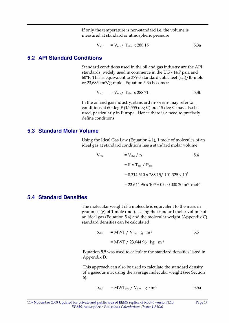
If only the temperature is non-standard i.e. the volume is measured at standard or atmospheric pressure
Vstd = Vobs/ Tobs x 288.15 5.3a
5.2 API Standard Conditions
Standard conditions used in the oil and gas industry are the API standards, widely used in commerce in the U.S - 14.7 psia and 60°F. This is equivalent to 379.3 standard cubic feet (scf)/lb-mole or 23,685 cm3/g-mole. Equation 5.3a becomes:
Vstd = Vobs/ Tobs x 288.71 5.3b
In the oil and gas industry, standard m3 or sm3 may refer to conditions at 60 deg F (15.555 deg C) but 15 deg C may also be used, particularly in Europe. Hence there is a need to precisely define conditions.
5.3 Standard Molar Volume
Using the Ideal Gas Law (Equation 4.1), 1 mole of molecules of an ideal gas at standard conditions has a standard molar volume
Vmol = Vstd / n 5.4
= R x Tstd / Pstd
= 8.314 510 x 288.15/ 101.325 x 103
= 23.644 96 x 10-3 ± 0.000 000 20 m3· mol-1
5.4 Standard Densities
The molecular weight of a molecule is equivalent to the mass in grammes (g) of 1 mole (mol). Using the standard molar volume of an ideal gas (Equation 5.4) and the molecular weight (Appendix C) standard densities can be calculated
ρstd = MWT / Vmol g · m-3 5.5
= MWT / 23.644 96 kg · m-3
Equation 5.5 was used to calculate the standard densities listed in Appendix D.
This approach can also be used to calculate the standard density of a gaseous mix using the average molecular weight (see Section 6).
ρstd = MWTave / Vmol g · m-3 5.5a
11th November 2008 Updated for private and public area of EEMS replica of Root-5 version 1.10 Page 18
EEMS-Atmospheric Emissions Calculations (Issue 1.810a)
= MWTave / 23.644 96 kg · m-3
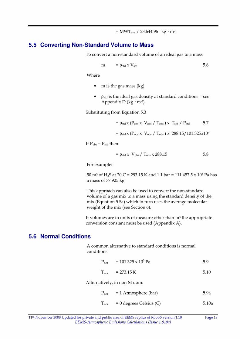
5.5 Converting Non-Standard Volume to Mass
To convert a non-standard volume of an ideal gas to a mass
m = ρstd x Vstd 5.6
Where
• m is the gas mass (kg)
• ρstd is the ideal gas density at standard conditions - see Appendix D (kg · m-3)
Substituting from Equation 5.3
= ρstd x (Pobs x Vobs / Tobs ) x Tstd / Pstd 5.7
= ρstd x (Pobs x Vobs / Tobs ) x 288.15/101.325x103
If Pobs = Pstd then
= ρstd x Vobs / Tobs x 288.15 5.8
For example:
50 m3 of H2S at 20 C = 293.15 K and 1.1 bar = 111.457 5 x 10³ Pa has a mass of 77.925 kg.
This approach can also be used to convert the non-standard volume of a gas mix to a mass using the standard density of the mix (Equation 5.5a) which in turn uses the average molecular weight of the mix (see Section 6).
If volumes are in units of measure other than m3 the appropriate conversion constant must be used (Appendix A).
5.6 Normal Conditions
A common alternative to standard conditions is normal conditions:
Pnor = 101.325 x 10³ Pa 5.9
Tnor = 273.15 K 5.10
Alternatively, in non-SI uom:
Pnor = 1 Atmosphere (bar) 5.9a
Tnor = 0 degrees Celsius (C) 5.10a
11th November 2008 Updated for private and public area of EEMS replica of Root-5 version 1.10 Page 19
EEMS-Atmospheric Emissions Calculations (Issue 1.810a)
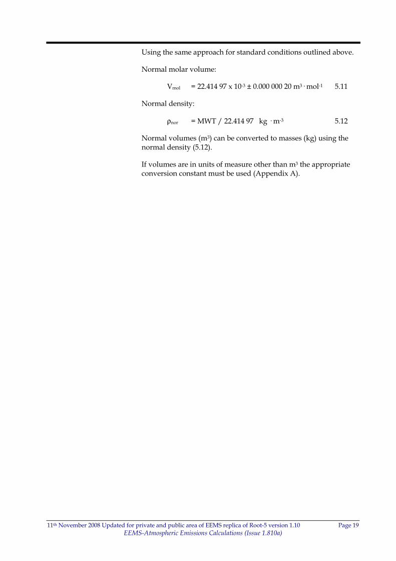
Using the same approach for standard conditions outlined above.
Normal molar volume:
Vmol = 22.414 97 x 10-3 ± 0.000 000 20 m3· mol-1 5.11
Normal density:
ρnor = MWT / 22.414 97 kg · m-3 5.12
Normal volumes (m3) can be converted to masses (kg) using the normal density (5.12).
If volumes are in units of measure other than m3 the appropriate conversion constant must be used (Appendix A).
11th November 2008 Updated for private and public area of EEMS replica of Root-5 version 1.10 Page 20
EEMS-Atmospheric Emissions Calculations (Issue 1.810a)
6 COMPONENT WEIGHTS
The composition of these gaseous mixes is normally expressed as component mole percentages (Cmol) i.e. what percentage of the total molecules are made up from each species. This is normally measured using gas chromatography.
Component mole percentages should be submitted by users to EEMS for all fuel, flare and vent gases. Fuel gas can been used as a default, in the absence of the flare and vent composition data, but this may lead to inaccuracies. In addition, the VOC molecular weight (MWT(VOC)) should also be submitted. If unavailable the agreed default for the UKCS is 40. Note that an updated approach involving full gas composition data is recommended by UKOOA for CO2 reporting for the European Emission Trading scheme but has not yet been incorporated into EEMS.
The relative weight Wtr for an emission gas (i) can be calculated from its component mole percentage and molecular weight.
Wtr(i) = Cmol(i)/100 x MWT(i) 6.1
The average molecular weight of the mix (MWTave) is calculated as the sum of all the relative weights, Wtr(i) in the mix.
MWTave = Σi Wtr(i) 6.2
From MWTave the standard molar density of the mix can be calculated using Equation 5.5a.
Finally the component weight percentage can be calculated
Cwt(i) = Wtr(i) / MWTave x 100 6.3
For example:
11th November 2008 Updated for private and public area of EEMS replica of Root-5 version 1.10 Page 21
EEMS-Atmospheric Emissions Calculations (Issue 1.810a)
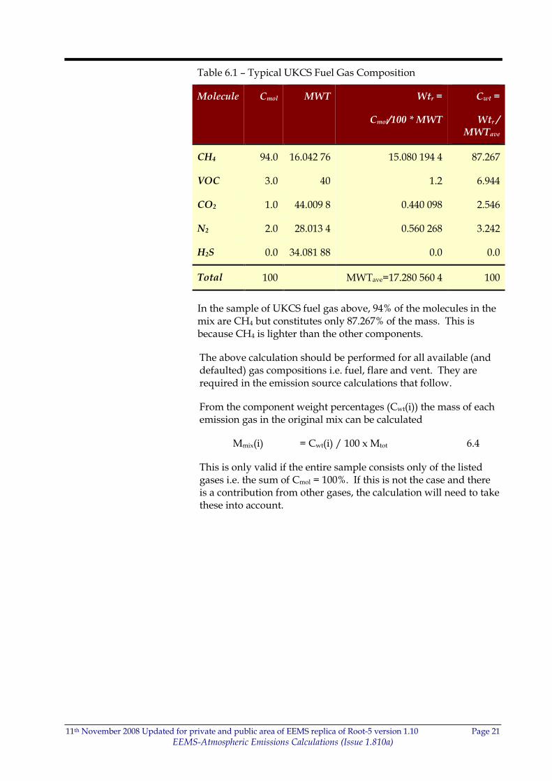
Table 6.1 – Typical UKCS Fuel Gas Composition
Molecule Cmol MWT Wtr =
Cmol/100 * MWT
Cwt =
Wtr / MWTave
CH4 94.0 16.042 76 15.080 194 4 87.267
VOC 3.0 40 1.2 6.944
CO2 1.0 44.009 8 0.440 098 2.546
N2 2.0 28.013 4 0.560 268 3.242
H2S 0.0 34.081 88 0.0 0.0
Total 100 MWTave=17.280 560 4 100
In the sample of UKCS fuel gas above, 94% of the molecules in the mix are CH4 but constitutes only 87.267% of the mass. This is because CH4 is lighter than the other components.
The above calculation should be performed for all available (and defaulted) gas compositions i.e. fuel, flare and vent. They are required in the emission source calculations that follow.
From the component weight percentages (Cwt(i)) the mass of each emission gas in the original mix can be calculated
Mmix(i) = Cwt(i) / 100 x Mtot 6.4
This is only valid if the entire sample consists only of the listed gases i.e. the sum of Cmol = 100%. If this is not the case and there is a contribution from other gases, the calculation will need to take these into account.
11th November 2008 Updated for private and public area of EEMS replica of Root-5 version 1.10 Page 22
EEMS-Atmospheric Emissions Calculations (Issue 1.810a)
7 EMISSION CALCULATION AND FACTORS
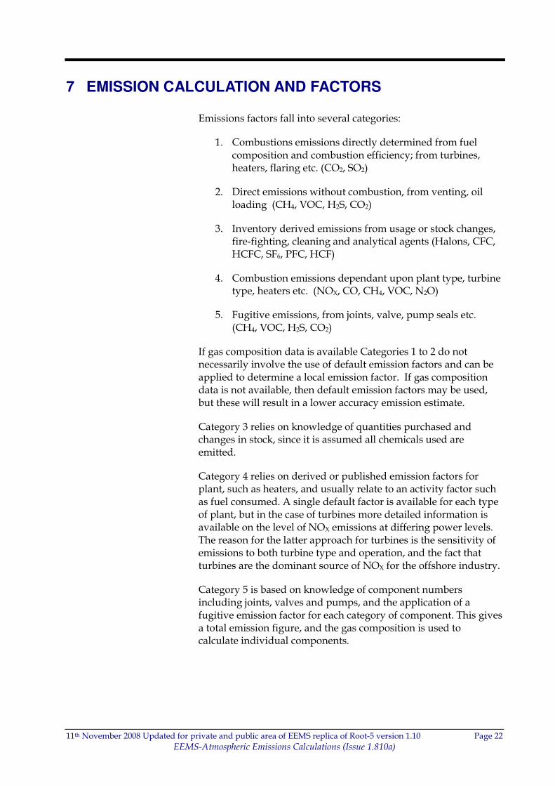
Emissions factors fall into several categories:
1. Combustions emissions directly determined from fuel composition and combustion efficiency; from turbines, heaters, flaring etc. (CO2, SO2)
2. Direct emissions without combustion, from venting, oil loading (CH4, VOC, H2S, CO2)
3. Inventory derived emissions from usage or stock changes, fire-fighting, cleaning and analytical agents (Halons, CFC, HCFC, SF6, PFC, HCF)
4. Combustion emissions dependant upon plant type, turbine type, heaters etc. (NOX, CO, CH4, VOC, N2O)
5. Fugitive emissions, from joints, valve, pump seals etc. (CH4, VOC, H2S, CO2)
If gas composition data is available Categories 1 to 2 do not necessarily involve the use of default emission factors and can be applied to determine a local emission factor. If gas composition data is not available, then default emission factors may be used, but these will result in a lower accuracy emission estimate.
Category 3 relies on knowledge of quantities purchased and changes in stock, since it is assumed all chemicals used are emitted.
Category 4 relies on derived or published emission factors for plant, such as heaters, and usually relate to an activity factor such as fuel consumed. A single default factor is available for each type of plant, but in the case of turbines more detailed information is available on the level of NOX emissions at differing power levels. The reason for the latter approach for turbines is the sensitivity of emissions to both turbine type and operation, and the fact that turbines are the dominant source of NOX for the offshore industry.
Category 5 is based on knowledge of component numbers including joints, valves and pumps, and the application of a fugitive emission factor for each category of component. This gives a total emission figure, and the gas composition is used to calculate individual components.
11th November 2008 Updated for private and public area of EEMS replica of Root-5 version 1.10 Page 23
EEMS-Atmospheric Emissions Calculations (Issue 1.810a)
7.1 Combustion Emissions
Combustion Efficiency
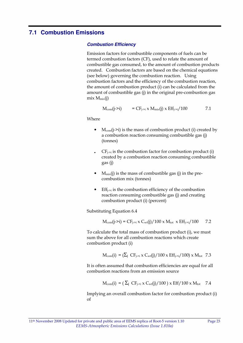
Emission factors for combustible components of fuels can be termed combustion factors (CF), used to relate the amount of combustible gas consumed, to the amount of combustion products created. Combustion factors are based on the chemical equations (see below) governing the combustion reaction. Using combustion factors and the efficiency of the combustion reaction, the amount of combustion product (i) can be calculated from the amount of combustible gas (j) in the original pre-combustion gas mix Mmix(j)
Mcom(j->i) = CFj->i x Mmix(j) x Effj->i/100 7.1
Where
• Mcom(j->i) is the mass of combustion product (i) created by a combustion reaction consuming combustible gas (j) (tonnes)
• CFj->i is the combustion factor for combustion product (i) created by a combustion reaction consuming combustible gas (j)
• Mmix(j) is the mass of combustible gas (j) in the pre-combustion mix (tonnes)
• Effj->i is the combustion efficiency of the combustion reaction consuming combustible gas (j) and creating combustion product (i) (percent)
Substituting Equation 6.4
Mcom(j->i) = CFj->i x Cwt(j)/100 x Mtot x Effj->i/100 7.2
To calculate the total mass of combustion product (i), we must sum the above for all combustion reactions which create combustion product (i)
Mcom(i) = (Σj CFj->i x Cwt(j)/100 x Effj->i/100) x Mtot 7.3
It is often assumed that combustion efficiencies are equal for all combustion reactions from an emission source
Mcom(i) = ( Σj CFj->i x Cwt(j)/100 ) x Eff/100 x Mtot 7.4
Implying an overall combustion factor for combustion product (i) of

11th November 2008 Updated for private and public area of EEMS replica of Root-5 version 1.10 Page 24
EEMS-Atmospheric Emissions Calculations (Issue 1.810a)
CF(i) = Σj CFj->i x Cwt(j)/100 7.5
7.1.1 CO2 Combustion Factor
CO2 is a product from the combustion of hydrocarbons:
o CH4
o VOCs
Using Equation 7.5
CF(CO2) = CFCH4->CO2 x Cwt(CH4)/100 +
CFVOC->CO2 x Cwt(VOC)/100 7.6
Methane Combustion
During the combustion of methane 1 molecule of CH4 results in 1 molecule of CO2 in the combustion products.
CH4 + 2 x O2 -> CO2 + 2 x H2O 7.7
The CO2 combustion factor for CH4 is the ratio of molecular weights of 1 x CO2 to 1 x CH4 (appendix C).
CFCH4->CO2 = 1 x MWT(CO2) / 1 x MWT(CH4)
= 44.009 8/16.042 76
= 2.743 28 7.8
In other words, 1 kg of combusted CH4 will release 2.743 28 kg of CO2.
VOC Combustion
During the combustion of ethane 2 molecules of C2H6 results in 4 molecules of CO2 in the combustion products.
2 x C2H6 + 7 x O2 -> 4 x CO2 + 6 x H2O 7.9
The CO2 combustion factor for C2H6 is the ratio of molecular weights of 4 x CO2 to 2 x C2H6.
CFC2H6->CO2 = 4 x MWT(CO2) / 2 x MWT(C2H6)
= 176.039 20 / 61.392 8
= 2.867 42 7.10
11th November 2008 Updated for private and public area of EEMS replica of Root-5 version 1.10 Page 25
EEMS-Atmospheric Emissions Calculations (Issue 1.810a)
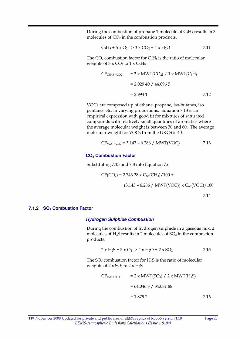
During the combustion of propane 1 molecule of C3H8 results in 3 molecules of CO2 in the combustion products.
C3H8 + 5 x O2 -> 3 x CO2 + 4 x H2O 7.11
The CO2 combustion factor for C3H8 is the ratio of molecular weights of 3 x CO2 to 1 x C3H8.
CFC3H8->CO2 = 3 x MWT(CO2) / 1 x MWT(C3H8)
= 2.029 40 / 44.096 5
= 2.994 1 7.12
VOCs are composed up of ethane, propane, iso-butanes, iso pentanes etc. in varying proportions. Equation 7.13 is an empirical expression with good fit for mixtures of saturated compounds with relatively small quantities of aromatics where the average molecular weight is between 30 and 60. The average molecular weight for VOCs from the UKCS is 40.
CFVOC->CO2 = 3.143 – 6.286 / MWT(VOC) 7.13
CO2 Combustion Factor
Substituting 7.13 and 7.8 into Equation 7.6
CF(CO2) = 2.743 28 x Cwt(CH4)/100 +
(3.143 – 6.286 / MWT(VOC)) x Cwt(VOC)/100
7.14
7.1.2 SO2 Combustion Factor
Hydrogen Sulphide Combustion
During the combustion of hydrogen sulphide in a gaseous mix, 2 molecules of H2S results in 2 molecules of SO2 in the combustion products.
2 x H2S + 3 x O2 -> 2 x H2O + 2 x SO2 7.15
The SO2 combustion factor for H2S is the ratio of molecular weights of 2 x SO2 to 2 x H2S.
CFH2S->SO2 = 2 x MWT(SO2) / 2 x MWT(H2S)
= 64.046 8 / 34.081 88
= 1.879 2 7.16
11th November 2008 Updated for private and public area of EEMS replica of Root-5 version 1.10 Page 26
EEMS-Atmospheric Emissions Calculations (Issue 1.810a)
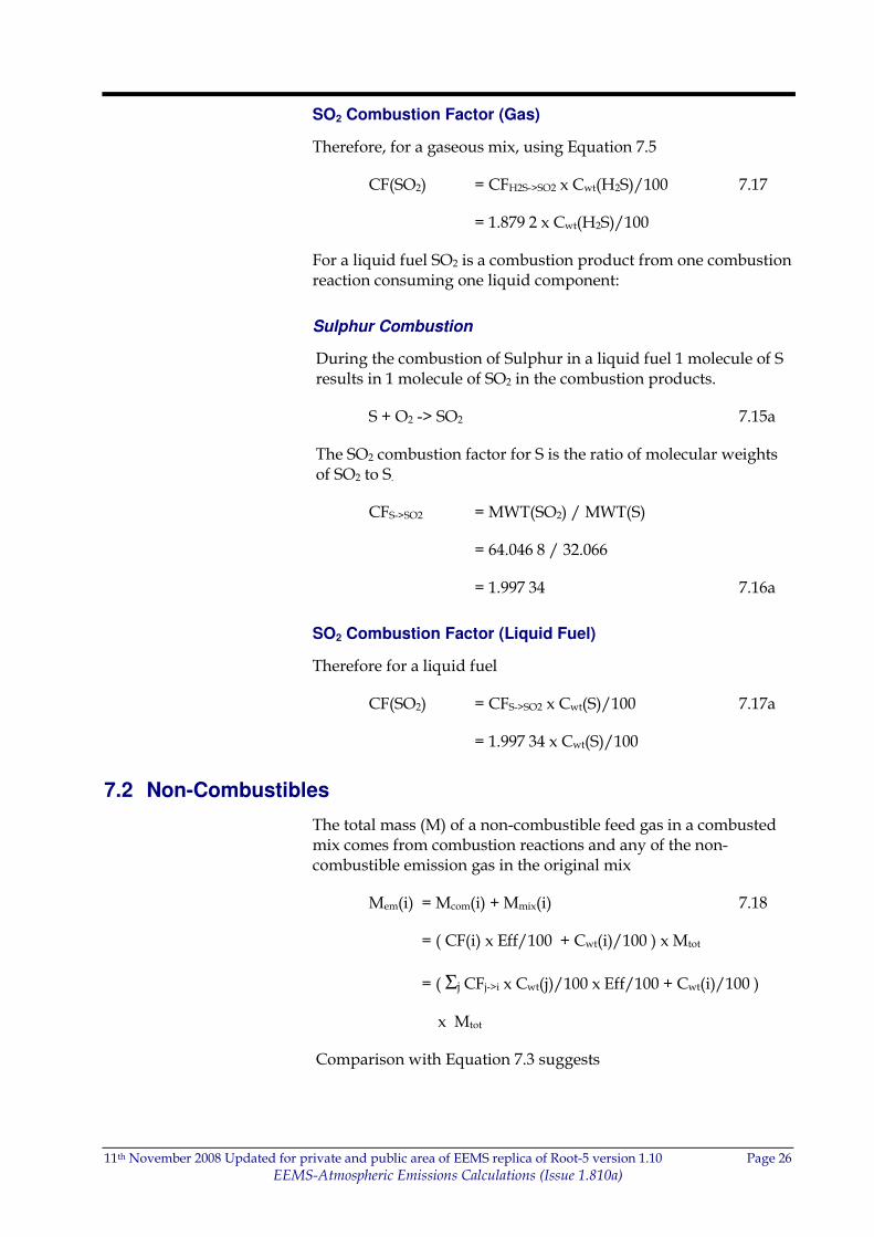
SO2 Combustion Factor (Gas)
Therefore, for a gaseous mix, using Equation 7.5
CF(SO2) = CFH2S->SO2 x Cwt(H2S)/100 7.17
= 1.879 2 x Cwt(H2S)/100
For a liquid fuel SO2 is a combustion product from one combustion reaction consuming one liquid component:
Sulphur Combustion
During the combustion of Sulphur in a liquid fuel 1 molecule of S results in 1 molecule of SO2 in the combustion products.
S + O2 -> SO2 7.15a
The SO2 combustion factor for S is the ratio of molecular weights of SO2 to S.
CFS->SO2 = MWT(SO2) / MWT(S)
= 64.046 8 / 32.066
= 1.997 34 7.16a
SO2 Combustion Factor (Liquid Fuel)
Therefore for a liquid fuel
CF(SO2) = CFS->SO2 x Cwt(S)/100 7.17a
= 1.997 34 x Cwt(S)/100
7.2 Non-Combustibles
The total mass (M) of a non-combustible feed gas in a combusted mix comes from combustion reactions and any of the non-combustible emission gas in the original mix
Mem(i) = Mcom(i) + Mmix(i) 7.18
= ( CF(i) x Eff/100 + Cwt(i)/100 ) x Mtot
= ( Σj CFj->i x Cwt(j)/100 x Eff/100 + Cwt(i)/100 )
x Mtot
Comparison with Equation 7.3 suggests
11th November 2008 Updated for private and public area of EEMS replica of Root-5 version 1.10 Page 27
EEMS-Atmospheric Emissions Calculations (Issue 1.810a)
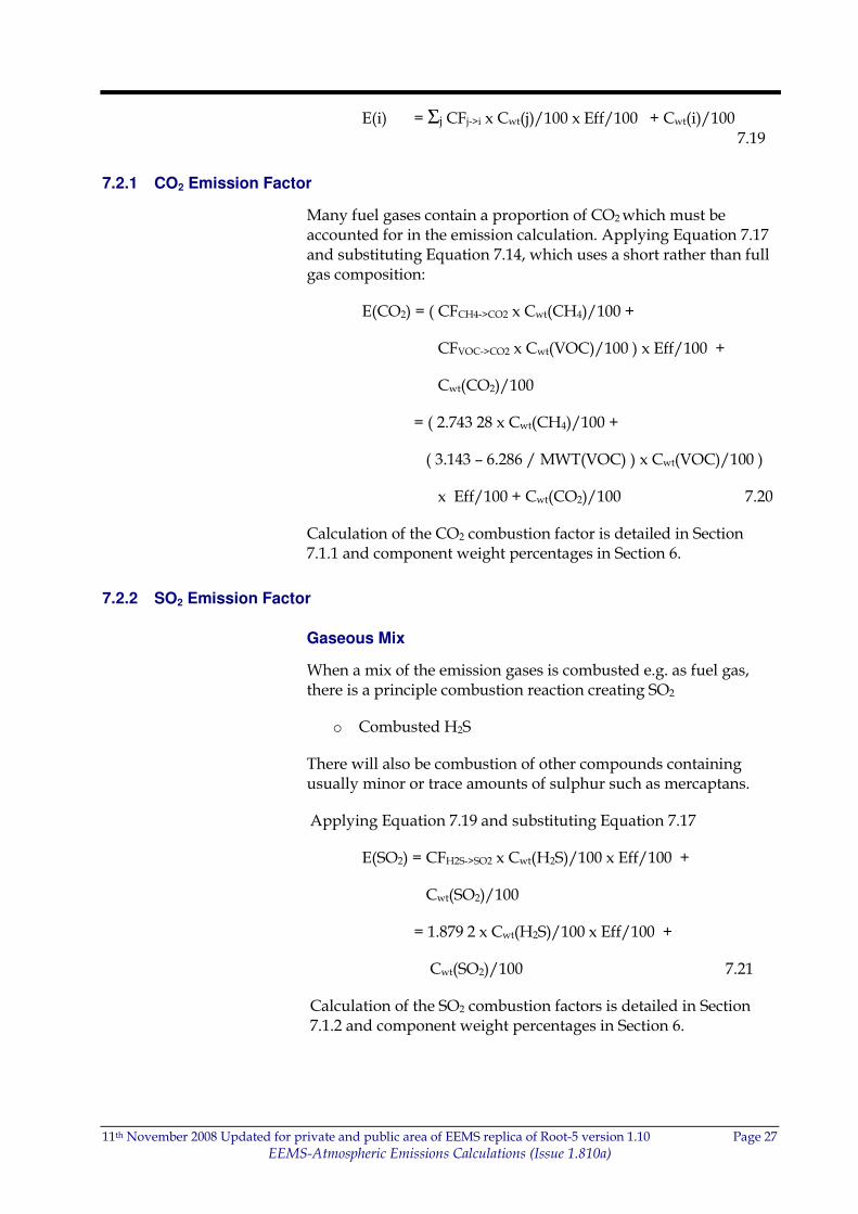
E(i) = Σj CFj->i x Cwt(j)/100 x Eff/100 + Cwt(i)/100 7.19
7.2.1 CO2 Emission Factor
Many fuel gases contain a proportion of CO2 which must be accounted for in the emission calculation. Applying Equation 7.17 and substituting Equation 7.14, which uses a short rather than full gas composition:
E(CO2) = ( CFCH4->CO2 x Cwt(CH4)/100 +
CFVOC->CO2 x Cwt(VOC)/100 ) x Eff/100 +
Cwt(CO2)/100
= ( 2.743 28 x Cwt(CH4)/100 +
( 3.143 – 6.286 / MWT(VOC) ) x Cwt(VOC)/100 )
x Eff/100 + Cwt(CO2)/100 7.20
Calculation of the CO2 combustion factor is detailed in Section 7.1.1 and component weight percentages in Section 6.
7.2.2 SO2 Emission Factor
Gaseous Mix
When a mix of the emission gases is combusted e.g. as fuel gas, there is a principle combustion reaction creating SO2
o Combusted H2S
There will also be combustion of other compounds containing usually minor or trace amounts of sulphur such as mercaptans.
Applying Equation 7.19 and substituting Equation 7.17
E(SO2) = CFH2S->SO2 x Cwt(H2S)/100 x Eff/100 +
Cwt(SO2)/100
= 1.879 2 x Cwt(H2S)/100 x Eff/100 +
Cwt(SO2)/100 7.21
Calculation of the SO2 combustion factors is detailed in Section 7.1.2 and component weight percentages in Section 6.
11th November 2008 Updated for private and public area of EEMS replica of Root-5 version 1.10 Page 28
EEMS-Atmospheric Emissions Calculations (Issue 1.810a)
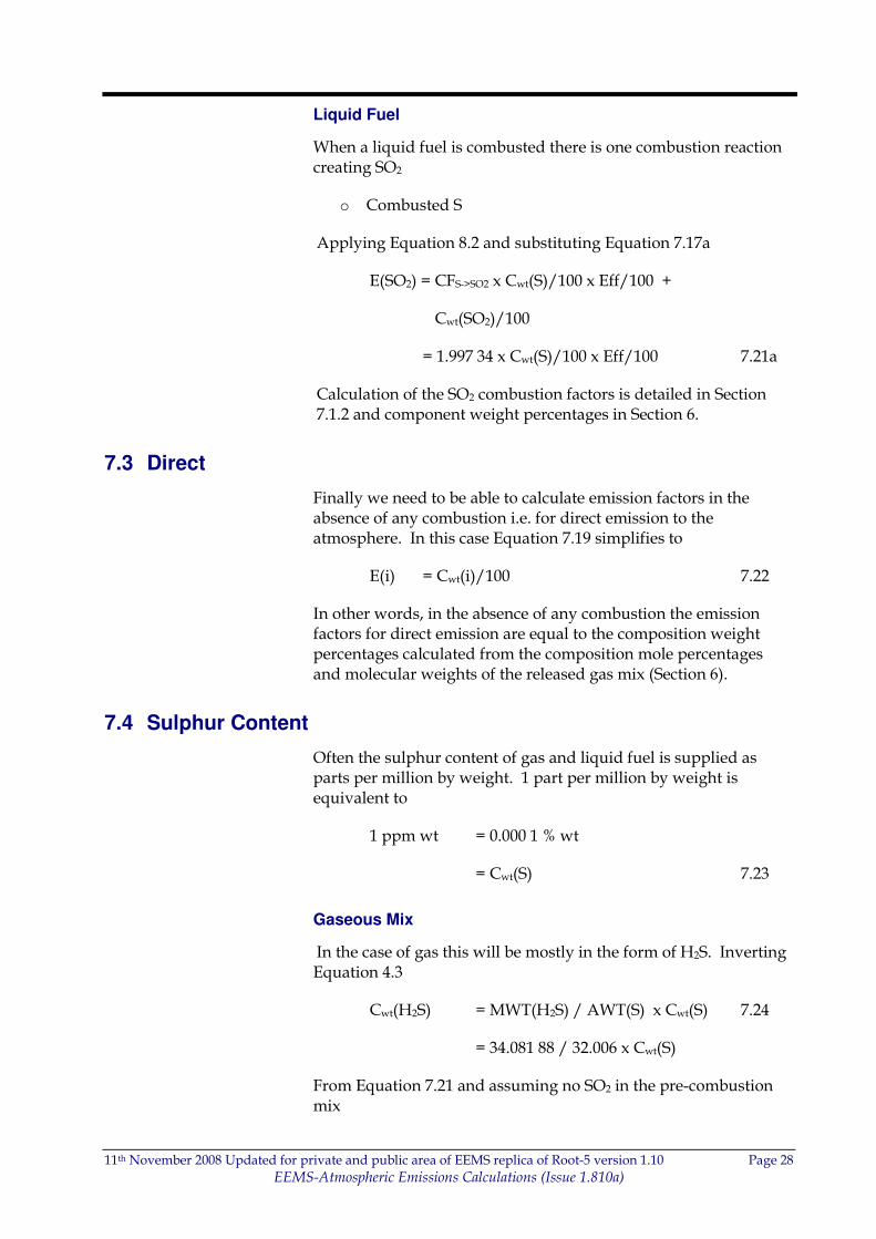
Liquid Fuel
When a liquid fuel is combusted there is one combustion reaction creating SO2
o Combusted S
Applying Equation 8.2 and substituting Equation 7.17a
E(SO2) = CFS->SO2 x Cwt(S)/100 x Eff/100 +
Cwt(SO2)/100
= 1.997 34 x Cwt(S)/100 x Eff/100 7.21a
Calculation of the SO2 combustion factors is detailed in Section 7.1.2 and component weight percentages in Section 6.
7.3 Direct
Finally we need to be able to calculate emission factors in the absence of any combustion i.e. for direct emission to the atmosphere. In this case Equation 7.19 simplifies to
E(i) = Cwt(i) /100 7.22
In other words, in the absence of any combustion the emission factors for direct emission are equal to the composition weight percentages calculated from the composition mole percentages and molecular weights of the released gas mix (Section 6).
7.4 Sulphur Content
Often the sulphur content of gas and liquid fuel is supplied as parts per million by weight. 1 part per million by weight is equivalent to
1 ppm wt = 0.000 1 % wt
= Cwt(S) 7.23
Gaseous Mix
In the case of gas this will be mostly in the form of H2S. Inverting Equation 4.3
Cwt(H2S) = MWT(H2S) / AWT(S) x Cwt(S) 7.24
= 34.081 88 / 32.006 x Cwt(S)
From Equation 7.21 and assuming no SO2 in the pre-combustion mix
11th November 2008 Updated for private and public area of EEMS replica of Root-5 version 1.10 Page 29
EEMS-Atmospheric Emissions Calculations (Issue 1.810a)
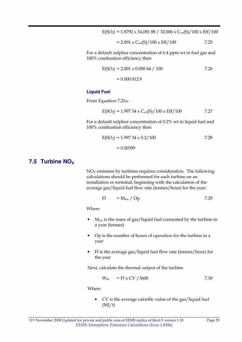
E(SO2) = 1.8792 x 34.081 88 / 32.006 x Cwt(S)/100 x Eff/100
= 2.001 x Cwt(S)/100 x Eff/100 7.25
For a default sulphur concentration of 6.4 ppm wt in fuel gas and 100% combustion efficiency then
E(SO2) = 2.001 x 0.000 64 / 100 7.26
= 0.000 012 8
Liquid Fuel
From Equation 7.21a:
E(SO2) = 1.997 34 x Cwt(S)/100 x Eff/100 7.27
For a default sulphur concentration of 0.2% wt in liquid fuel and 100% combustion efficiency then
E(SO2) = 1.997 34 x 0.2/100 7.28
= 0.00399
7.5 Turbine NOX
NOX emission by turbines requires consideration. The following calculations should be performed for each turbine on an installation or terminal, beginning with the calculation of the average gas/liquid fuel flow rate (tonnes/hour) for the year:
Fl = Mtur / Op 7.29
Where
• Mtur is the mass of gas/liquid fuel consumed by the turbine in a year (tonnes)
• Op is the number of hours of operation for the turbine in a year
• Fl is the average gas/liquid fuel flow rate (tonnes/hour) for the year
Next, calculate the thermal output of the turbine
Wth = Fl x CV /3600 7.30
Where
• CV is the average calorific value of the gas/liquid fuel (MJ/t)

11th November 2008 Updated for private and public area of EEMS replica of Root-5 version 1.10 Page 30
EEMS-Atmospheric Emissions Calculations (Issue 1.810a)
• 3600 is the number of seconds in an hour
• Wth is the thermal output of the turbine (megawatts)
NOX emissions are dependent on the type and power of the turbine. The harder the turbine is working the more NOX will be emitted. The actual relationship is expressed as an empirical second order polynomial relating the thermal input of the turbine (Wth) in MW to the NOX emission factor
Etur(NOX) = a + b x Wth + c x Wth2 7.31
Each make and model of turbine has an assigned UKOOA reference and an approved set of polynomial coefficients a, b, and c (Appendix E)
The NOX emission from each turbine can then be calculated
Mtur(NOX) = Etur(NOX) x Mtur 7.32
The total gas/liquid fuel consumed can be calculated by summing the mass for each turbine
Mtot = Σtur Mtur 7.33
The total NOX emission can be calculated by summing the mass for each turbine
Mem(NOX) = Σtur Mtur(NOX) 7.34
An effective NOX emission factor for all turbines can then be inferred by
E(NOX) = Mem(NOX) / Mtot 7.35
11th November 2008 Updated for private and public area of EEMS replica of Root-5 version 1.10 Page 31
EEMS-Atmospheric Emissions Calculations (Issue 1.810a)
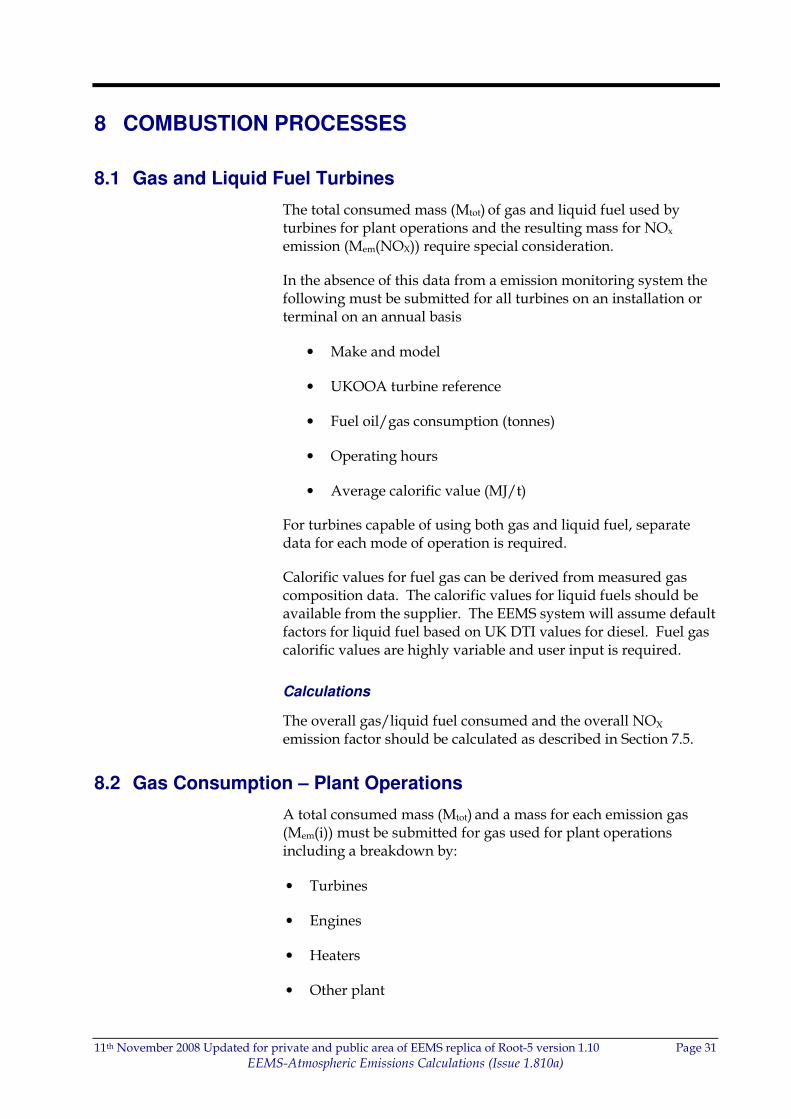
8 COMBUSTION PROCESSES
8.1 Gas and Liquid Fuel Turbines
The total consumed mass (Mtot) of gas and liquid fuel used by turbines for plant operations and the resulting mass for NOx emission (Mem(NOX)) require special consideration.
In the absence of this data from a emission monitoring system the following must be submitted for all turbines on an installation or terminal on an annual basis
• Make and model
• UKOOA turbine reference
• Fuel oil/gas consumption (tonnes)
• Operating hours
• Average calorific value (MJ/t)
For turbines capable of using both gas and liquid fuel, separate data for each mode of operation is required.
Calorific values for fuel gas can be derived from measured gas composition data. The calorific values for liquid fuels should be available from the supplier. The EEMS system will assume default factors for liquid fuel based on UK DTI values for diesel. Fuel gas calorific values are highly variable and user input is required.
Calculations
The overall gas/liquid fuel consumed and the overall NOX emission factor should be calculated as described in Section 7.5.
8.2 Gas Consumption – Plant Operations
A total consumed mass (Mtot) and a mass for each emission gas (Mem(i)) must be submitted for gas used for plant operations including a breakdown by:
• Turbines
• Engines
• Heaters
• Other plant
11th November 2008 Updated for private and public area of EEMS replica of Root-5 version 1.10 Page 32
EEMS-Atmospheric Emissions Calculations (Issue 1.810a)
Defaults
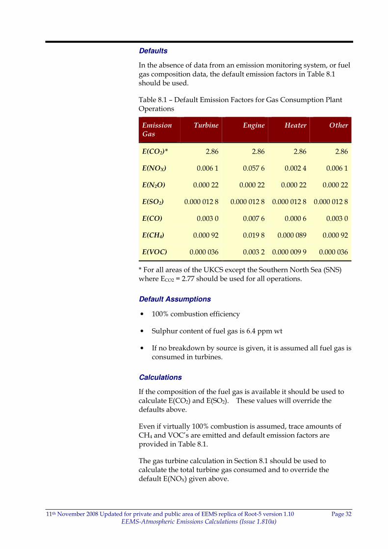
In the absence of data from an emission monitoring system, or fuel gas composition data, the default emission factors in Table 8.1 should be used.
Table 8.1 – Default Emission Factors for Gas Consumption Plant Operations
Emission Gas
Turbine Engine Heater Other
E(CO2)* 2.86 2.86 2.86 2.86
E(NOX) 0.006 1 0.057 6 0.002 4 0.006 1
E(N2O) 0.000 22 0.000 22 0.000 22 0.000 22
E(SO2) 0.000 012 8 0.000 012 8 0.000 012 8 0.000 012 8
E(CO) 0.003 0 0.007 6 0.000 6 0.003 0
E(CH4) 0.000 92 0.019 8 0.000 089 0.000 92
E(VOC) 0.000 036 0.003 2 0.000 009 9 0.000 036
* For all areas of the UKCS except the Southern North Sea (SNS) where ECO2 = 2.77 should be used for all operations.
Default Assumptions
• 100% combustion efficiency
• Sulphur content of fuel gas is 6.4 ppm wt
• If no breakdown by source is given, it is assumed all fuel gas is consumed in turbines.
Calculations
If the composition of the fuel gas is available it should be used to calculate E(CO2) and E(SO2). These values will override the defaults above.
Even if virtually 100% combustion is assumed, trace amounts of CH4 and VOC’s are emitted and default emission factors are provided in Table 8.1.
The gas turbine calculation in Section 8.1 should be used to calculate the total turbine gas consumed and to override the default E(NOX) given above.
11th November 2008 Updated for private and public area of EEMS replica of Root-5 version 1.10 Page 33
EEMS-Atmospheric Emissions Calculations (Issue 1.810a)
The following values can then be calculated:
• Mem(i) = E(i) x Mtot for each of the emission gases
• Sum of Mem(i) for turbines, engines, heaters and others
8.3 Diesel Consumption – Plant Operations
A total consumed mass and a mass for each emission gas must be submitted for diesel used for plant operations including a breakdown by:
• Turbines
• Engines
• Heaters
Where available the sulphur weight composition (Cwt(S)) of the consumed diesel should be submitted.
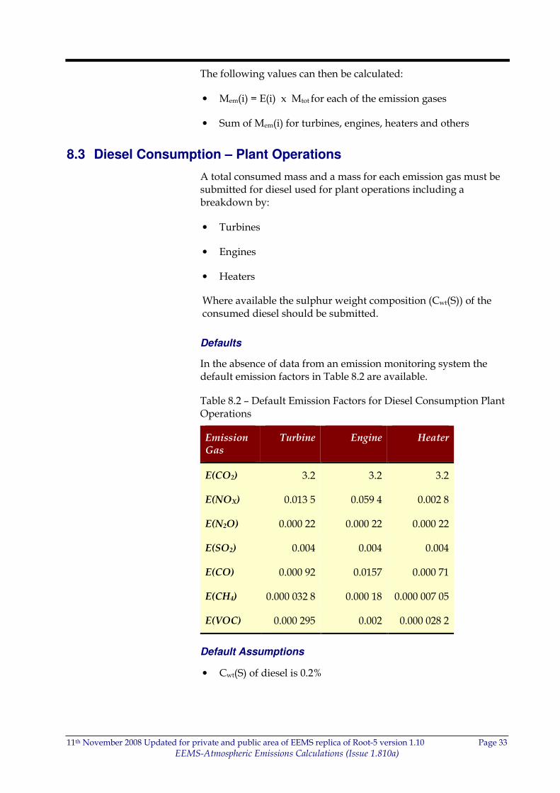
Defaults
In the absence of data from an emission monitoring system the default emission factors in Table 8.2 are available.
Table 8.2 – Default Emission Factors for Diesel Consumption Plant Operations
Emission Gas
Turbine Engine Heater
E(CO2) 3.2 3.2 3.2
E(NOX) 0.013 5 0.059 4 0.002 8
E(N2O) 0.000 22 0.000 22 0.000 22
E(SO2) 0.004 0.004 0.004
E(CO) 0.000 92 0.0157 0.000 71
E(CH4) 0.000 032 8 0.000 18 0.000 007 05
E(VOC) 0.000 295 0.002 0.000 028 2
Default Assumptions
• Cwt(S) of diesel is 0.2%
11th November 2008 Updated for private and public area of EEMS replica of Root-5 version 1.10 Page 34
EEMS-Atmospheric Emissions Calculations (Issue 1.810a)
Calculations
If a sulphur content of the diesel is available from the supplier, it should be used to calculate E(SO2) as described in Section 7.4 Equation 7.24. This value will override the default above.
The liquid fuel turbine calculation described in Section 8.1 should be used for the total turbine gas consumed and to override the default E(NOX) given above.
The following values can then be calculated:
• Mem(i) = E(i) x Mtot for each of the emission gases
• Sum of Mem(i) for turbines, engines and heaters.
8.4 Fuel Oil Consumption – Plant Operations
A total consumed mass and a mass for each emission gas must be submitted for fuel oil used for plant operations including a breakdown by:
• Turbines
• Engines
• Heaters
The sulphur content (Cwt(S)) of the fuel oil should be submitted.
Defaults
In the absence of data from a verified system the default emission factors in Table 8.2 should be used (see previous section).
Default Assumptions
• Cwt(S) of diesel is 0.2%, no specific default factor for fuel oil is provided as this may vary widely.
Calculations
If a sulphur content of the fuel oil is available it should be used to calculate E(SO2) as described in Section 7.4 Equation 7.24. This value will override the default above.
The following values can then be calculated:
• Mem(i) = E(i) x Mtot for each of the emission gases
• Sum of Mem(i) for turbines, engines and heaters
11th November 2008 Updated for private and public area of EEMS replica of Root-5 version 1.10 Page 35
EEMS-Atmospheric Emissions Calculations (Issue 1.810a)
8.5 Gas Flaring
A total consumed mass and a mass for each emission gas must be submitted for flared gas including a breakdown by:
• Routine operations
• Maintenance
• Upsets/Other
Alternatively a gross figure can be submitted where the above breakdown of figures is unavailable
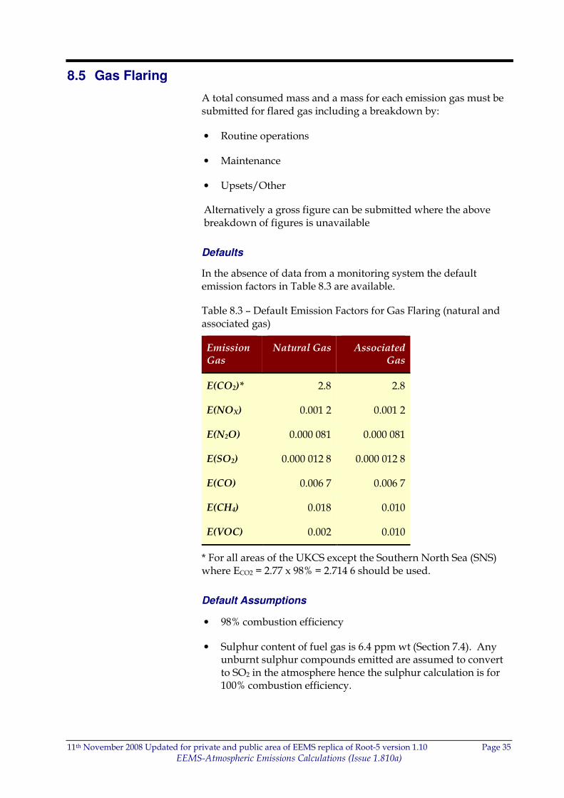
Defaults
In the absence of data from a monitoring system the default emission factors in Table 8.3 are available.
Table 8.3 – Default Emission Factors for Gas Flaring (natural and associated gas)
Emission Gas
Natural Gas Associated Gas
E(CO2)* 2.8 2.8
E(NOX) 0.001 2 0.001 2
E(N2O) 0.000 081 0.000 081
E(SO2) 0.000 012 8 0.000 012 8
E(CO) 0.006 7 0.006 7
E(CH4) 0.018 0.010
E(VOC) 0.002 0.010
* For all areas of the UKCS except the Southern North Sea (SNS) where ECO2 = 2.77 x 98% = 2.714 6 should be used.
Default Assumptions
• 98% combustion efficiency
• Sulphur content of fuel gas is 6.4 ppm wt (Section 7.4). Any unburnt sulphur compounds emitted are assumed to convert to SO2 in the atmosphere hence the sulphur calculation is for 100% combustion efficiency.
11th November 2008 Updated for private and public area of EEMS replica of Root-5 version 1.10 Page 36
EEMS-Atmospheric Emissions Calculations (Issue 1.810a)
Calculations
If a mole composition of the fuel gas is available it should be used to calculate E(CO2), E(CH4), E(VOC) and E(SO2) as described in Section 7. E(CH4) and E(VOC) emission factors are required since combustion is less than 100% efficient = 98%. These calculated values override the defaults above.
The following values can then be calculated:
• Mem(i) = E(i) x Mtot for each of the emission gases
• Sum of Mem(i) for routine operations, maintenance and Upsets/Others

11th November 2008 Updated for private and public area of EEMS replica of Root-5 version 1.10 Page 37
EEMS-Atmospheric Emissions Calculations (Issue 1.810a)
9 DIRECT EMISSION
9.1 Gas Venting
A total emission mass and a mass for each emission gas must be submitted for vented gas including a breakdown by:
• Operational
• Maintenance
• Emergency
Alternatively a gross figure can be submitted where a breakdown is unavailable.
Defaults
In the absence of data from a verified system the default emission factors in Table 9.1 is available.
Table 9.1 – Default Emission Factors for Gas Venting (natural and associated gas)
Emission Gas
Natural Gas Associated Gas
E(CO2) 0 0
E(NOX) 0 0
E(N2O) 0 0
E(SO2) 0 0
E(CO) 0 0
E(CH4) 0.9 0.5
E(VOC) 0.1 0.5
Default Assumptions
• The default assumptions are crude as the composition of flare and vented gas is widely variable. Users should enter measured, or if not available design composition data rather than rely on default values.

11th November 2008 Updated for private and public area of EEMS replica of Root-5 version 1.10 Page 38
EEMS-Atmospheric Emissions Calculations (Issue 1.810a)
Calculations
If the composition of the vent gas is available it should be used to calculate emission factors as described in Section 7.3. These calculated values override the defaults above.
The following values can then be calculated:
• Mem(i) = E(i) x Mtot for each of the emission gases
• Sum of Mem(i) for operational, maintenance and emergency
9.2 Direct Process Emissions
A total emission mass and a mass for each emission gas must be submitted for direct process emissions for all active plant in the installation.
There are no calculations available for this data. The full data must be submitted.
9.3 Oil Loading
A total emission mass and a mass for each emission gas must be submitted for oil loading emissions including a breakdown by:
• Ship
• Rail/Trucks
Defaults
In the absence of data from a verified system the default emission factors in Table 9.2 should be used.
11th November 2008 Updated for private and public area of EEMS replica of Root-5 version 1.10 Page 39
EEMS-Atmospheric Emissions Calculations (Issue 1.810a)
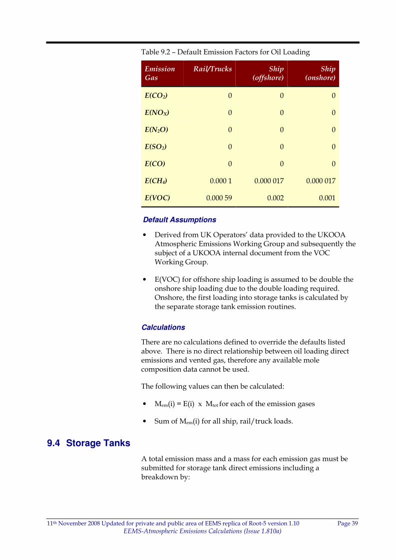
Table 9.2 – Default Emission Factors for Oil Loading
Emission Gas
Rail/Trucks Ship (offshore)
Ship (onshore)
E(CO2) 0 0 0
E(NOX) 0 0 0
E(N2O) 0 0 0
E(SO2) 0 0 0
E(CO) 0 0 0
E(CH4) 0.000 1 0.000 017 0.000 017
E(VOC) 0.000 59 0.002 0.001
Default Assumptions
• Derived from UK Operators’ data provided to the UKOOA Atmospheric Emissions Working Group and subsequently the subject of a UKOOA internal document from the VOC Working Group.
• E(VOC) for offshore ship loading is assumed to be double the onshore ship loading due to the double loading required. Onshore, the first loading into storage tanks is calculated by the separate storage tank emission routines.
Calculations
There are no calculations defined to override the defaults listed above. There is no direct relationship between oil loading direct emissions and vented gas, therefore any available mole composition data cannot be used.
The following values can then be calculated:
• Mem(i) = E(i) x Mtot for each of the emission gases
• Sum of Mem(i) for all ship, rail/truck loads.
9.4 Storage Tanks
A total emission mass and a mass for each emission gas must be submitted for storage tank direct emissions including a breakdown by:
11th November 2008 Updated for private and public area of EEMS replica of Root-5 version 1.10 Page 40
EEMS-Atmospheric Emissions Calculations (Issue 1.810a)
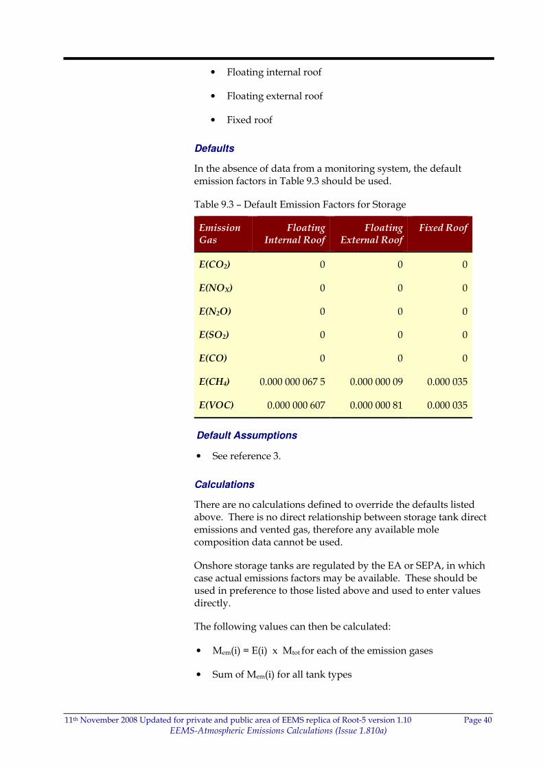
• Floating internal roof
• Floating external roof
• Fixed roof
Defaults
In the absence of data from a monitoring system, the default emission factors in Table 9.3 should be used.
Table 9.3 – Default Emission Factors for Storage
Emission Gas
Floating Internal Roof
Floating External Roof
Fixed Roof
E(CO2) 0 0 0
E(NOX) 0 0 0
E(N2O) 0 0 0
E(SO2) 0 0 0
E(CO) 0 0 0
E(CH4) 0.000 000 067 5 0.000 000 09 0.000 035
E(VOC) 0.000 000 607 0.000 000 81 0.000 035
Default Assumptions
• See reference 3.
Calculations
There are no calculations defined to override the defaults listed above. There is no direct relationship between storage tank direct emissions and vented gas, therefore any available mole composition data cannot be used.
Onshore storage tanks are regulated by the EA or SEPA, in which case actual emissions factors may be available. These should be used in preference to those listed above and used to enter values directly.
The following values can then be calculated:
• Mem(i) = E(i) x Mtot for each of the emission gases
• Sum of Mem(i) for all tank types
11th November 2008 Updated for private and public area of EEMS replica of Root-5 version 1.10 Page 41
EEMS-Atmospheric Emissions Calculations (Issue 1.810a)
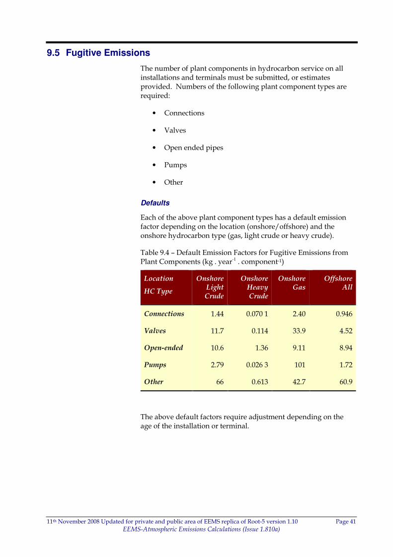
9.5 Fugitive Emissions
The number of plant components in hydrocarbon service on all installations and terminals must be submitted, or estimates provided. Numbers of the following plant component types are required:
• Connections
• Valves
• Open ended pipes
• Pumps
• Other
Defaults
Each of the above plant component types has a default emission factor depending on the location (onshore/offshore) and the onshore hydrocarbon type (gas, light crude or heavy crude).
Table 9.4 – Default Emission Factors for Fugitive Emissions from Plant Components (kg . year-1 . component-1)
Location
HC Type
Onshore Light Crude
Onshore Heavy Crude
Onshore Gas
Offshore All
Connections 1.44 0.070 1 2.40 0.946
Valves 11.7 0.114 33.9 4.52
Open-ended 10.6 1.36 9.11 8.94
Pumps 2.79 0.026 3 101 1.72
Other 66 0.613 42.7 60.9
The above default factors require adjustment depending on the age of the installation or terminal.
11th November 2008 Updated for private and public area of EEMS replica of Root-5 version 1.10 Page 42
EEMS-Atmospheric Emissions Calculations (Issue 1.810a)
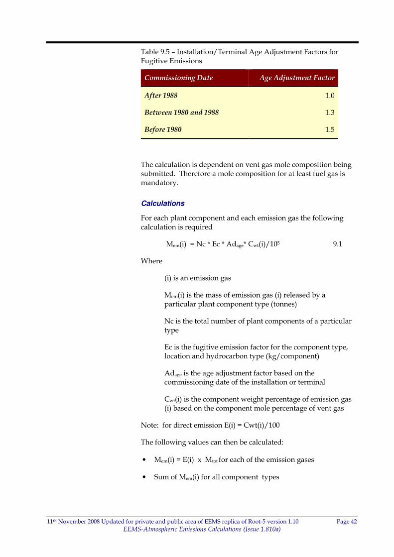
Table 9.5 – Installation/Terminal Age Adjustment Factors for Fugitive Emissions
Commissioning Date Age Adjustment Factor
After 1988 1.0
Between 1980 and 1988 1.3
Before 1980 1.5
The calculation is dependent on vent gas mole composition being submitted. Therefore a mole composition for at least fuel gas is mandatory.
Calculations
For each plant component and each emission gas the following calculation is required
Mem(i) = Nc * Ec * Adage* Cwt(i)/105 9.1
Where
(i) is an emission gas
Mem(i) is the mass of emission gas (i) released by a particular plant component type (tonnes)
Nc is the total number of plant components of a particular type
Ec is the fugitive emission factor for the component type, location and hydrocarbon type (kg/component)
Adage is the age adjustment factor based on the commissioning date of the installation or terminal
Cwt(i) is the component weight percentage of emission gas (i) based on the component mole percentage of vent gas
Note: for direct emission E(i) = Cwt(i)/100
The following values can then be calculated:
• Mem(i) = E(i) x Mtot for each of the emission gases
• Sum of Mem(i) for all component types
11th November 2008 Updated for private and public area of EEMS replica of Root-5 version 1.10 Page 43
EEMS-Atmospheric Emissions Calculations (Issue 1.810a)
9.6 Halogenated Compounds
A total stored and emitted quantity for each of the halogenated compounds listed in Table 2.3 must be submitted. For HFCs, PFCs and SF6 the emitted masses of each individual species (k) must also be reported. These masses must also be converted to CO2 equivalents using the published factors (Appendix F).
Meq(CO2) = Mem(k) x Feq(k) 9.1
11th November 2008 Updated for private and public area of EEMS replica of Root-5 version 1.10 Page 44
EEMS-Atmospheric Emissions Calculations (Issue 1.810a)
10 DRILLING
10.1 Well Testing
A total consumed mass and a mass for each emission gas must be submitted for gas used during well testing. The following raw data must be supplied:
• Well name
• Hydrocarbon type
• Total testing quantity
Defaults
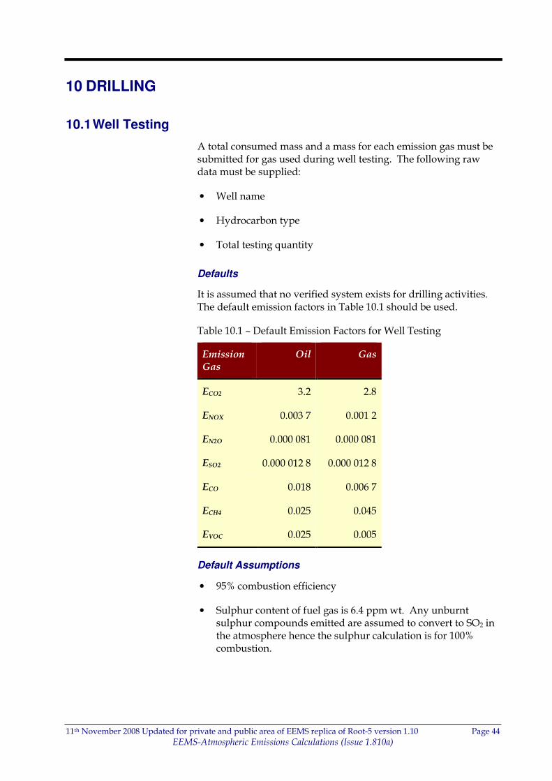
It is assumed that no verified system exists for drilling activities. The default emission factors in Table 10.1 should be used.
Table 10.1 – Default Emission Factors for Well Testing
Emission Gas
Oil Gas
ECO2 3.2 2.8
ENOX 0.003 7 0.001 2
EN2O 0.000 081 0.000 081
ESO2 0.000 012 8 0.000 012 8
ECO 0.018 0.006 7
ECH4 0.025 0.045
EVOC 0.025 0.005
Default Assumptions
• 95% combustion efficiency
• Sulphur content of fuel gas is 6.4 ppm wt. Any unburnt sulphur compounds emitted are assumed to convert to SO2 in the atmosphere hence the sulphur calculation is for 100% combustion.
11th November 2008 Updated for private and public area of EEMS replica of Root-5 version 1.10 Page 45
EEMS-Atmospheric Emissions Calculations (Issue 1.810a)
Calculations
If a gas composition of the test gas is available it should be used to calculate E(CO2), E(CH4,) E(VOC) and E(SO2) as described in Section 7 assuming a combustion efficiency of 95%, or 100% in the case of SO2. These values will override the defaults above.
The following values can then be calculated:
• Mem(i) = E(i) x Mtot for each of the emission gases
• Sum of Mem(i) for all wells
10.2 Diesel Consumption
A total consumed mass and a mass for each emission gas must be submitted for diesel used during all well testing.
Where available the sulphur content (Cwt(S)) of the diesel must also be submitted.
Defaults
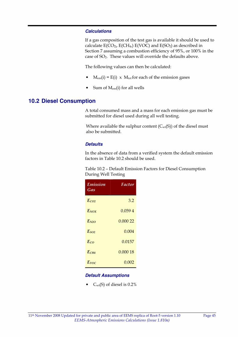
In the absence of data from a verified system the default emission factors in Table 10.2 should be used.
Table 10.2 – Default Emission Factors for Diesel Consumption During Well Testing
Emission Gas
Factor
ECO2 3.2
ENOX 0.059 4
EN2O 0.000 22
ESO2 0.004
ECO 0.0157
ECH4 0.000 18
EVOC 0.002
Default Assumptions
• Cwt(S) of diesel is 0.2%

11th November 2008 Updated for private and public area of EEMS replica of Root-5 version 1.10 Page 46
EEMS-Atmospheric Emissions Calculations (Issue 1.810a)
Calculations
If a sulphur content of the diesel is available it should be used to calculate E(SO2) as described in Section 7.4 Equation 7.24. This value will override the default above.
The following values can then be calculated:
• Mem(i) = E(i) x Mtot for each of the emission gases
• Sum of Mem(i) for all wells (see above) with Mem(i) for diesel consumption
11th November 2008 Updated for private and public area of EEMS replica of Root-5 version 1.10 Page 47
EEMS-Atmospheric Emissions Calculations (Issue 1.810a)
APPENDIX A –CONVERSION CONSTANTS
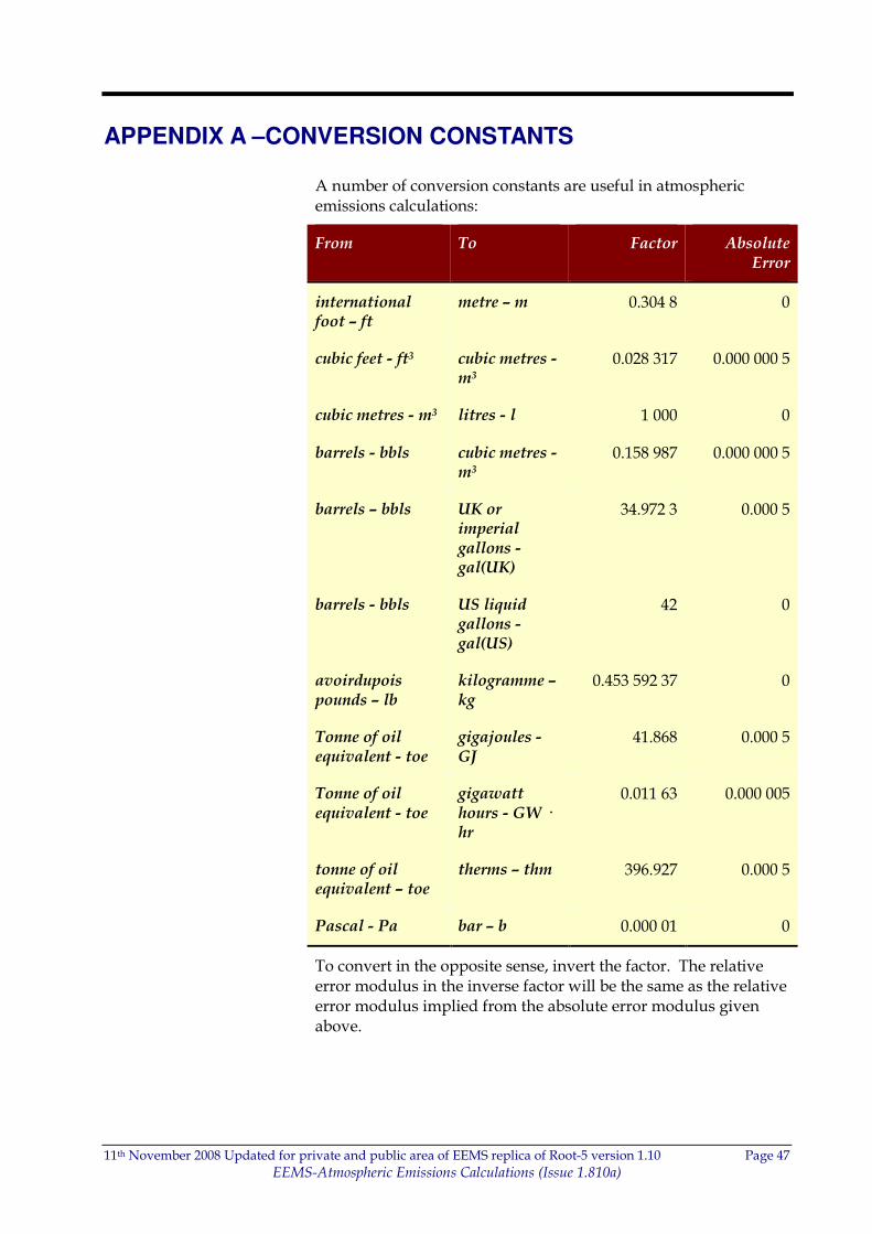
A number of conversion constants are useful in atmospheric emissions calculations:
From To Factor Absolute Error
international foot – ft
metre – m 0.304 8 0
cubic feet - ft3 cubic metres - m3
0.028 317 0.000 000 5
cubic metres - m3 litres - l 1 000 0
barrels - bbls cubic metres - m3
0.158 987 0.000 000 5
barrels – bbls UK or imperial gallons - gal(UK)
34.972 3 0.000 5
barrels - bbls US liquid gallons - gal(US)
42 0
avoirdupois pounds – lb
kilogramme – kg
0.453 592 37 0
Tonne of oil equivalent - toe
gigajoules - GJ
41.868 0.000 5
Tonne of oil equivalent - toe
gigawatt hours - GW · hr
0.011 63 0.000 005
tonne of oil equivalent – toe
therms – thm 396.927 0.000 5
Pascal - Pa bar – b 0.000 01 0
To convert in the opposite sense, invert the factor. The relative error modulus in the inverse factor will be the same as the relative error modulus implied from the absolute error modulus given above.
11th November 2008 Updated for private and public area of EEMS replica of Root-5 version 1.10 Page 48
EEMS-Atmospheric Emissions Calculations (Issue 1.810a)
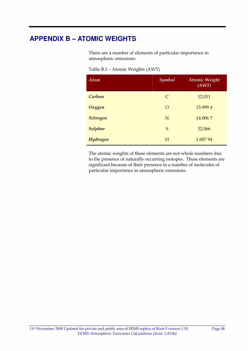
APPENDIX B – ATOMIC WEIGHTS
There are a number of elements of particular importance in atmospheric emissions:
Table B.1 – Atomic Weights (AWT)
Atom Symbol Atomic Weight (AWT)
Carbon C 12.011
Oxygen O 15.999 4
Nitrogen N 14.006 7
Sulphur S 32.066
Hydrogen H 1.007 94
The atomic weights of these elements are not whole numbers due to the presence of naturally occurring isotopes. These elements are significant because of their presence in a number of molecules of particular importance in atmospheric emissions.
11th November 2008 Updated for private and public area of EEMS replica of Root-5 version 1.10 Page 49
EEMS-Atmospheric Emissions Calculations (Issue 1.810a)
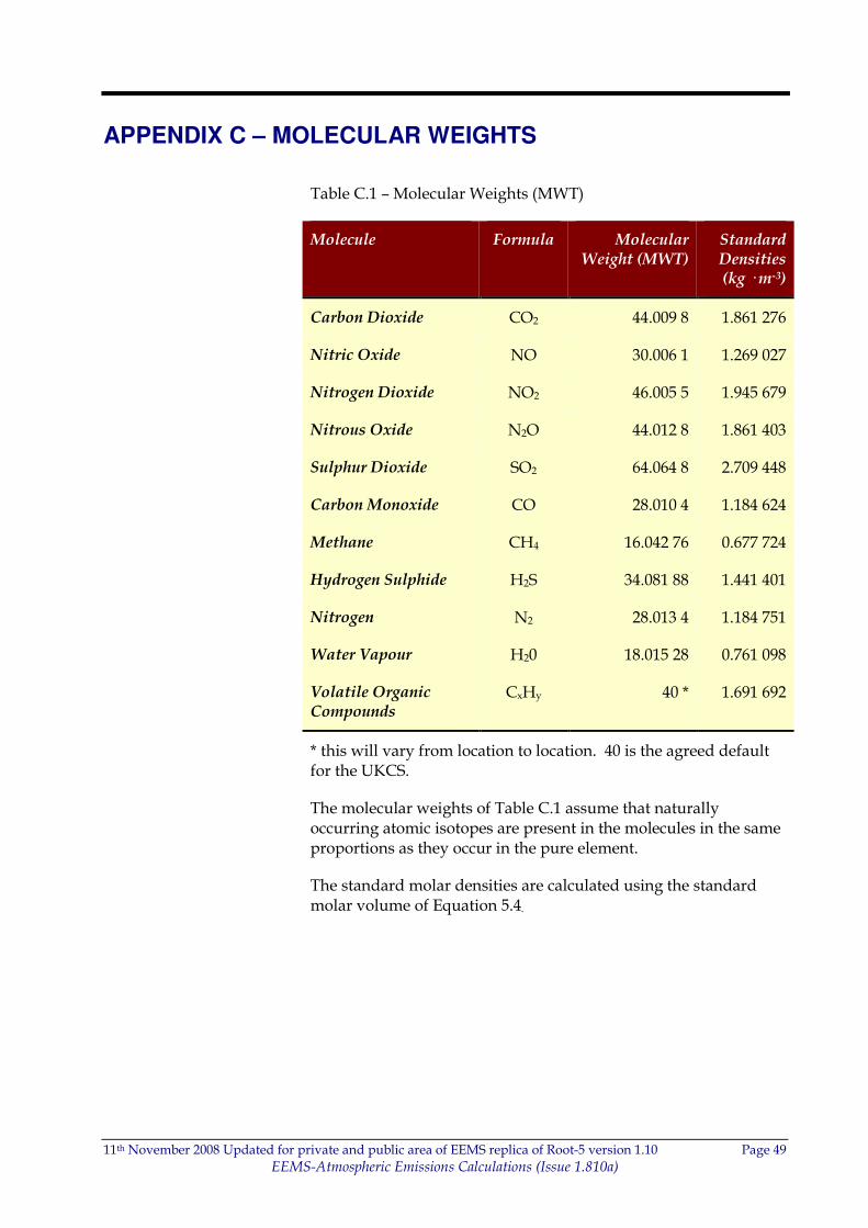
APPENDIX C – MOLECULAR WEIGHTS
Table C.1 – Molecular Weights (MWT)
Molecule Formula Molecular Weight (MWT)
Standard Densities (kg · m-3)
Carbon Dioxide CO2 44.009 8 1.861 276
Nitric Oxide NO 30.006 1 1.269 027
Nitrogen Dioxide NO2 46.005 5 1.945 679
Nitrous Oxide N2O 44.012 8 1.861 403
Sulphur Dioxide SO2 64.064 8 2.709 448
Carbon Monoxide CO 28.010 4 1.184 624
Methane CH4 16.042 76 0.677 724
Hydrogen Sulphide H2S 34.081 88 1.441 401
Nitrogen N2 28.013 4 1.184 751
Water Vapour H20 18.015 28 0.761 098
Volatile Organic Compounds
CxHy 40 * 1.691 692
* this will vary from location to location. 40 is the agreed default for the UKCS.
The molecular weights of Table C.1 assume that naturally occurring atomic isotopes are present in the molecules in the same proportions as they occur in the pure element.
The standard molar densities are calculated using the standard molar volume of Equation 5.4.
11th November 2008 Updated for private and public area of EEMS replica of Root-5 version 1.10 Page 50
EEMS-Atmospheric Emissions Calculations (Issue 1.810a)
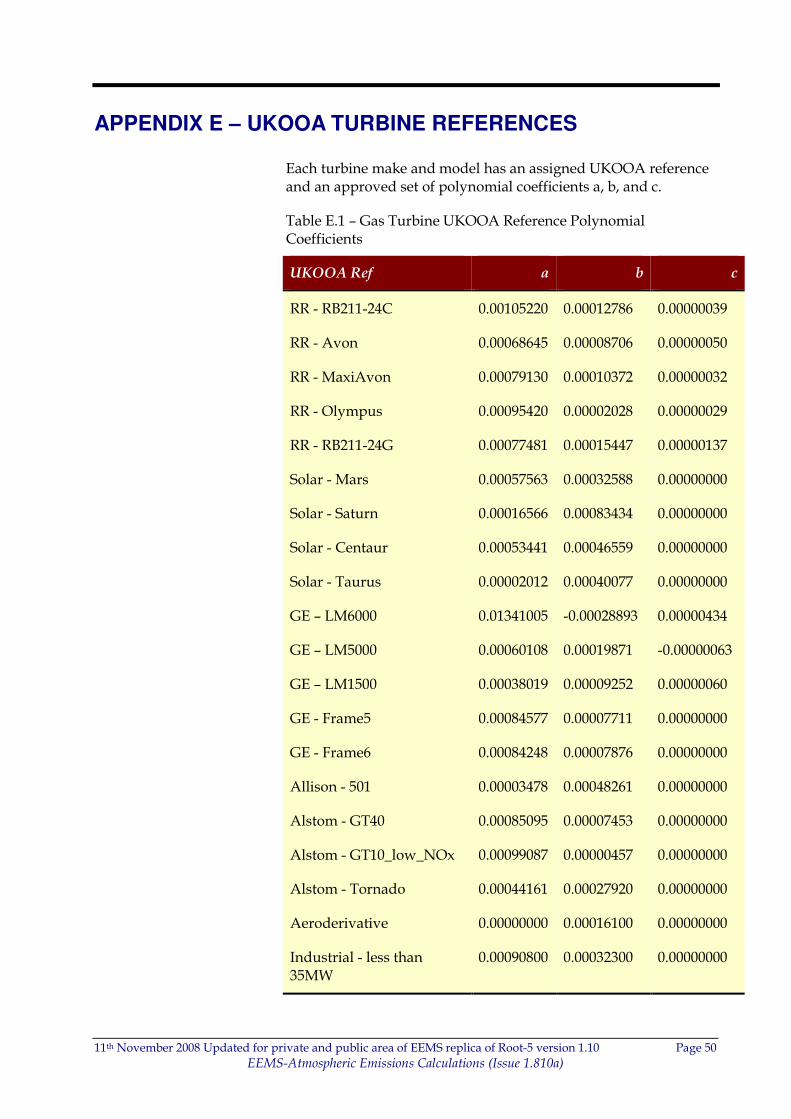
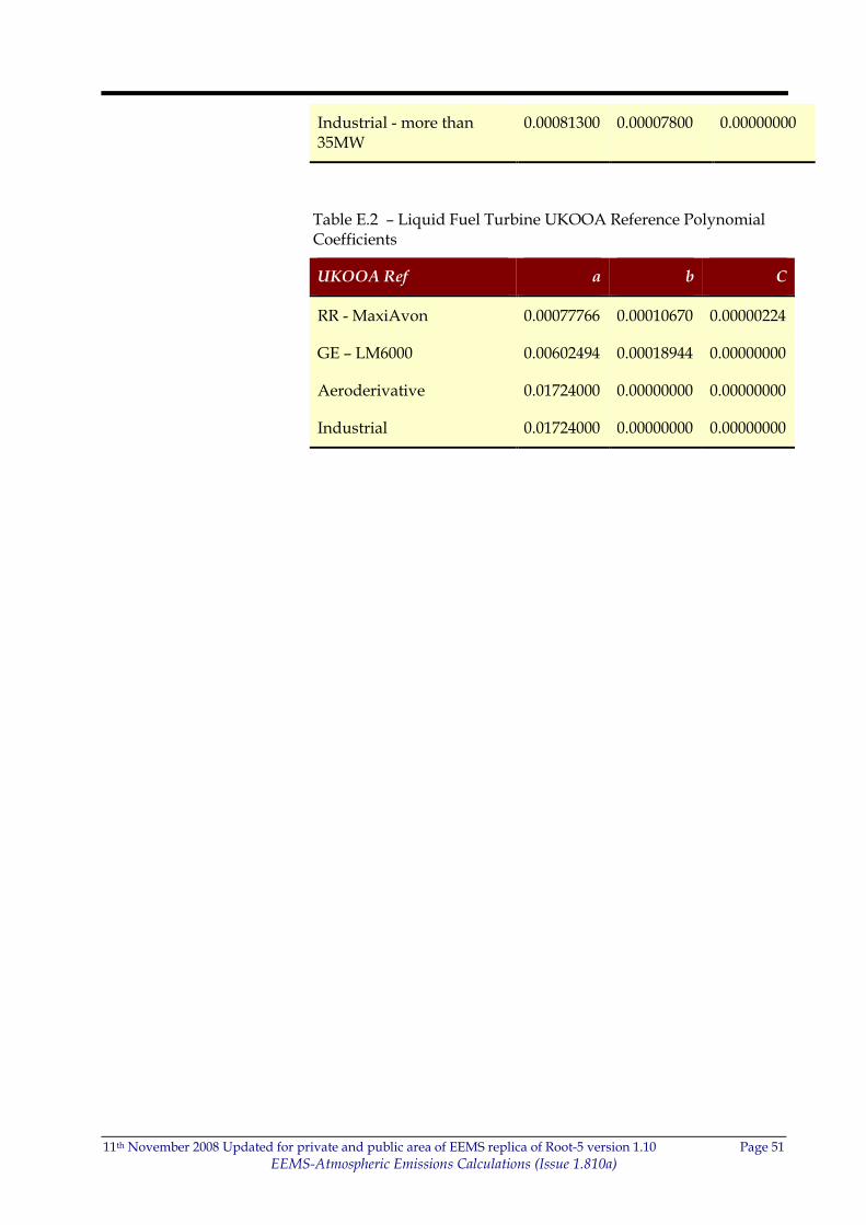
APPENDIX E – UKOOA TURBINE REFERENCES
Each turbine make and model has an assigned UKOOA reference and an approved set of polynomial coefficients a, b, and c.
Table E.1 – Gas Turbine UKOOA Reference Polynomial Coefficients
UKOOA Ref a b c
RR - RB211-24C 0.00105220 0.00012786 0.00000039
RR - Avon 0.00068645 0.00008706 0.00000050
RR - MaxiAvon 0.00079130 0.00010372 0.00000032
RR - Olympus 0.00095420 0.00002028 0.00000029
RR - RB211-24G 0.00077481 0.00015447 0.00000137
Solar - Mars 0.00057563 0.00032588 0.00000000
Solar - Saturn 0.00016566 0.00083434 0.00000000
Solar - Centaur 0.00053441 0.00046559 0.00000000
Solar - Taurus 0.00002012 0.00040077 0.00000000
GE – LM6000 0.01341005 -0.00028893 0.00000434
GE – LM5000 0.00060108 0.00019871 -0.00000063
GE – LM1500 0.00038019 0.00009252 0.00000060
GE - Frame5 0.00084577 0.00007711 0.00000000
GE - Frame6 0.00084248 0.00007876 0.00000000
Allison - 501 0.00003478 0.00048261 0.00000000
Alstom - GT40 0.00085095 0.00007453 0.00000000
Alstom - GT10_low_NOx 0.00099087 0.00000457 0.00000000
Alstom - Tornado 0.00044161 0.00027920 0.00000000
Aeroderivative 0.00000000 0.00016100 0.00000000
Industrial - less than 35MW
0.00090800 0.00032300 0.00000000
11th November 2008 Updated for private and public area of EEMS replica of Root-5 version 1.10 Page 51
EEMS-Atmospheric Emissions Calculations (Issue 1.810a)
Industrial - more than 35MW
0.00081300 0.00007800 0.00000000
Table E.2 – Liquid Fuel Turbine UKOOA Reference Polynomial Coefficients
UKOOA Ref a b C
RR - MaxiAvon 0.00077766 0.00010670 0.00000224
GE – LM6000 0.00602494 0.00018944 0.00000000
Aeroderivative 0.01724000 0.00000000 0.00000000
Industrial 0.01724000 0.00000000 0.00000000
11th November 2008 Updated for private and public area of EEMS replica of Root-5 version 1.10 Page 52
EEMS-Atmospheric Emissions Calculations (Issue 1.810a)
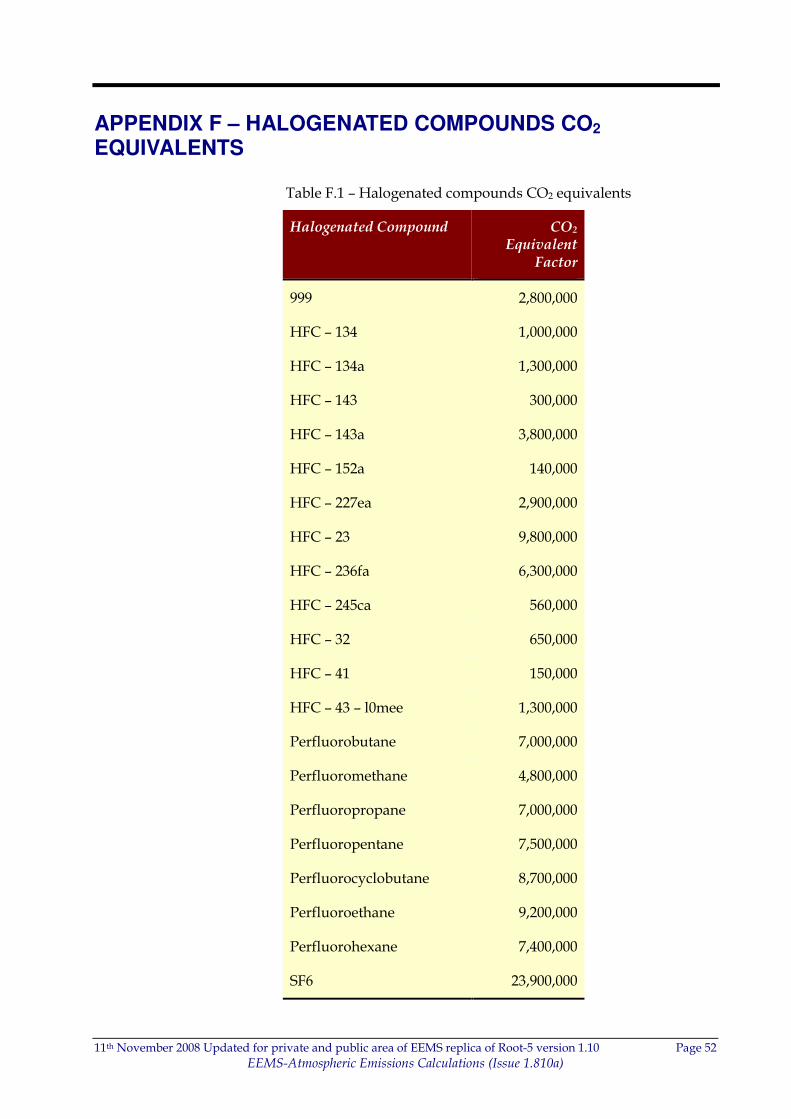
APPENDIX F – HALOGENATED COMPOUNDS CO2 EQUIVALENTS
Table F.1 – Halogenated compounds CO2 equivalents
Halogenated Compound CO2 Equivalent
Factor
999 2,800,000
HFC – 134 1,000,000
HFC – 134a 1,300,000
HFC – 143 300,000
HFC – 143a 3,800,000
HFC – 152a 140,000
HFC – 227ea 2,900,000
HFC – 23 9,800,000
HFC – 236fa 6,300,000
HFC – 245ca 560,000
HFC – 32 650,000
HFC – 41 150,000
HFC – 43 – l0mee 1,300,000
Perfluorobutane 7,000,000
Perfluoromethane 4,800,000
Perfluoropropane 7,000,000
Perfluoropentane 7,500,000
Perfluorocyclobutane 8,700,000
Perfluoroethane 9,200,000
Perfluorohexane 7,400,000
SF6 23,900,000
11th November 2008 Updated for private and public area of EEMS replica of Root-5 version 1.10 Page 53
EEMS-Atmospheric Emissions Calculations (Issue 1.810a)
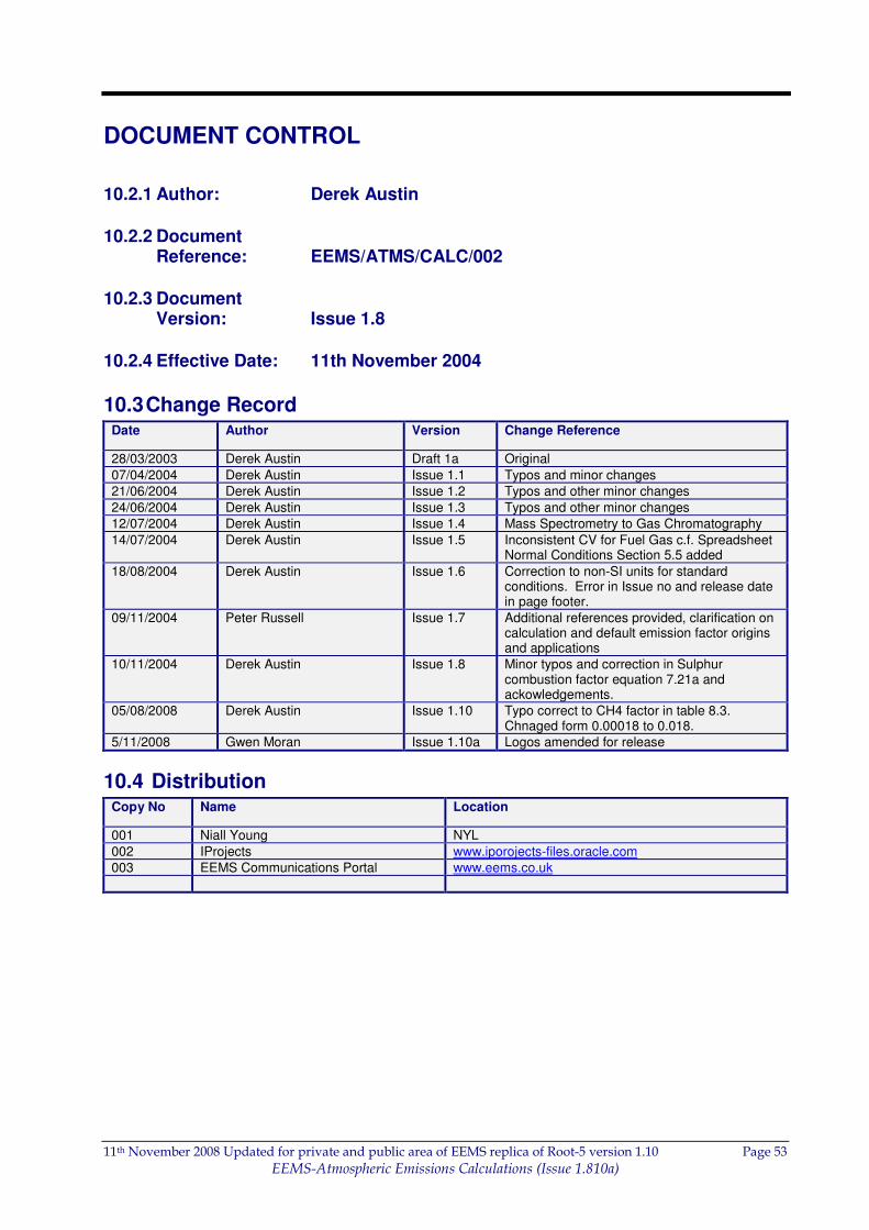
DOCUMENT CONTROL
10.2.1 Author: Derek Austin
10.2.2 Document Reference: EEMS/ATMS/CALC/002
10.2.3 Document Version: Issue 1.8
10.2.4 Effective Date: 11th November 2004
10.3 Change Record Date Author Version Change Reference
28/03/2003 Derek Austin Draft 1a Original
07/04/2004 Derek Austin Issue 1.1 Typos and minor changes
21/06/2004 Derek Austin Issue 1.2 Typos and other minor changes
24/06/2004 Derek Austin Issue 1.3 Typos and other minor changes
12/07/2004 Derek Austin Issue 1.4 Mass Spectrometry to Gas Chromatography
14/07/2004 Derek Austin Issue 1.5 Inconsistent CV for Fuel Gas c.f. Spreadsheet Normal Conditions Section 5.5 added
18/08/2004 Derek Austin Issue 1.6 Correction to non-SI units for standard conditions. Error in Issue no and release date in page footer.
09/11/2004 Peter Russell Issue 1.7 Additional references provided, clarification on calculation and default emission factor origins and applications
10/11/2004 Derek Austin Issue 1.8 Minor typos and correction in Sulphur combustion factor equation 7.21a and ackowledgements.
05/08/2008 Derek Austin Issue 1.10 Typo correct to CH4 factor in table 8.3. Chnaged form 0.00018 to 0.018.
5/11/2008 Gwen Moran Issue 1.10a Logos amended for release
10.4 Distribution Copy No Name Location
001 Niall Young NYL
002 IProjects www.iporojects-files.oracle.com
003 EEMS Communications Portal www.eems.co.uk