eeg-based brain computer interface for smart home control ...eprints.utem.edu.my/18093/1/eeg-based...
TRANSCRIPT

EEG-based Brain Computer Interface for Smart Home Control Using Arduino
TAN CHEER SHEN
This Report Is Submitted In partial Fulfillment of Requirements For The Bachelor Degree in Electronic Engineering (Industrial Electronic)
Fakulti Kejuruteraan Elektronik dan Kejuruteraan Komputer Universiti Teknikal Malaysia Melaka
June 2016

ii
UNIVERSTI TEKNIKAL MALAYSIA MELAKA FAKULTI KEJURUTERAAN ELEKTRONIK DAN KEJURUTERAAN KOMPUTER
BORANG PENGESAHAN STATUS LAPORAN PROJEK SARJANA MUDA II
Tajuk Projek : EEG-based Brain Computer Interface for Smart Home Control Using Arduino
Sesi Pengajian : 1 5 / 1 6
TAN CHEER SHEN Saya ……………………………………………………………………………………………
mengaku membenarkan Laporan Projek Sarjana Muda ini disimpan di Perpustakaan dengan syarat-syarat kegunaan seperti berikut:
1. Laporan adalah hakmilik Universiti Teknikal Malaysia Melaka.
2. Perpustakaan dibenarkan membuat salinan untuk tujuan pengajian sahaja.
3. Perpustakaan dibenarkan membuat salinan laporan ini sebagai bahan pertukaran antara institusi
pengajian tinggi.
4. Sila tandakan ( √ ) :
SULIT*
*(Mengandungi maklumat yang berdarjah keselamatan atau
kepentingan Malaysia seperti yang termaktub di dalam AKTA RAHSIA RASMI 1972)
TERHAD**
**(Mengandungi maklumat terhad yang telah ditentukan oleh
organisasi/badan di mana penyelidikan dijalankan)
TIDAK TERHAD
Disahkan oleh:
__ ________________________ ___________________________________ (TANDATANGAN PENULIS) (COP DAN TANDATANGAN PENYELIA)
Tarikh: ……………………….. Tarikh: ………………………..

iii
“I hereby declared that this report entitled EEG-based Brain Computer Interface for Smart Home Control Using Arduino is a result of my own except for the notes that have
been cited clearly in the references” Signature : ………………………………………… Student Name : TAN CHEER SHEN Date : 15 JUNE 2016

iv
“I hereby declared I have read this report and in my opinion, this report is sufficient in term of the scope and quality for the award the Bachelor of Electronics Engineering
(Industrial Electronic) with honours” Signature : ………………………………………… Supervisor Name : DR. LOW YIN FEN Date : 15 JUNE 2016

v
Specially dedicate to my beloved parents and also to my siblings and friends who give
encouragement and support for me to complete this project. For my supervisor, Dr. Low
Yin Fen who gave me a lot of guidance and advices throughout this project until
successfully. Thank you very much to all of you.

vi
ACKNOWLEDGEMENT
Firstly, I would like to express my deepest appreciation to the Universiti Teknikal
Malaysia Melaka (UTeM) for letting me fulfill my degree holder in Bachelor of Electronic
Engineering. I would also like to thank the Faculty of Electronic and Computer
Engineering (FKEKK) for giving me the opportunity to write an honours thesis. Besides,
I would like to express my sincere gratitude to my advisor Dr. Low Yin Fen for the
continuous support of my Bachelor Degree study and related research, for her patience,
motivation, and immense knowledge. Her guidance helped me in all the time research and
writing of this thesis.

vii
ABSTRACT
Electroencephalography (EEG) is a technique that acquiring of neural electrical
activity of human by placing electrodes to human scalp. EEG-based Brain Computer
Interface (BCI) for smart home is a system that allows direct communication between
human brain and the computer. The main objective of this project was to generate control
signals that can be used as commands to control a simple smart home system. This
included development of a prototype for smart home system which can let the user to have
visualization towards the smart home system. In order to achieve the target, EEG signal
was first acquired by using low cost Emotiv EPOC device. Then, the EEG signal was
analyzed and classified by using MATLAB software. The feature extraction method was
set at amplitude of the EEG signal after the signal was analyzed and trained. Furthermore,
the classified signal was used to control a real-time feature of home appliances by sending
a command to Arduino UNO devices. Therefore, communication between Emotiv EPOC
devices with computer is then established to turn on and off of the home appliances.
Moreover, a user friendly graphical user interface (GUI) was developed which assist the
real time communication between Emotiv EPOC and smart home system. Last but not
least, the quality of life was improved besides ease the life of disabled people.

viii
ABSTRAK
Electroencephalography (EEG) adalah satu teknik yang merekodkan aktiviti-
aktiviti neural manusia dengan meletakkan elektrod pada kulit kepala manusia. EEG
berdasarkan berhubungan antara otak manusia dan komputer (BCI) untuk rumah pintar
adalah satu system yang menjalin komunikasi secara langsung antara otak dan computer.
Objektif utama projek ini adalah untuk mejana isyarat kawalan yang boleh digunakan
sebagai arahan untuk mengawal sistem rumah pintar mudah. Projek ini termasuk
pembinaan prototaip untuk sistem rumah pintar yang membolehkan pengguna mempunyai
visualisasi ke arah sistem rumah pintar. Dalam usaha untuk mencapai sasaran itu, isyarat
EEG pertama kali diperolehi dengan menggunakan kos rendah peranti Emotiv EPOC.
Kemudian, isyarat EEG telah dianalisis dan dikelaskan dengan menggunakan perisian
MATLAB. Kaedah ciri pengekstrakan telah ditetapkan pada amplitud isyarat EEG selepas
isyarat dianalisis dan terlatih. Tambahan pula, isyarat yang diklasifikasikan digunakan
untuk mengawal ciri-ciri masa sebenar peralatan rumah dengan menghantar arahan untuk
peranti UNO Arduino. Oleh itu, komunikasi antara peranti Emotiv EPOC dengan
komputer kemudiannya ditubuhkan untuk menghidupkan dan mematikan daripada
peralatan rumah. Selain itu, persahabatan antara muka pengguna grafik pengguna (GUI)
telah dibangunkan yang membantu komunikasi masa sebenar antara Emotiv EPOC dan
sistem rumah pintar. Akhir sekali, kualiti hidup telah bertambah baik di samping
meringankan kehidupan orang kurang upaya.

ix
TABLE OF CONTENT
CHAPTER CONTENT PAGE PROJECT TITLE i
CONFIRMATION OF REPORT STATUS ii
DECLARATION iii
SUPERVISOR’S CONFIRMATION iv
DEDICATION v
ACKNOWLEDGEMENT vi
ABSTRACT vii
ABSTRAK viii
TABLE OF CONTENT ix
LIST OF TABLES xi
LIST OF FIGURES xii
LIST OF ABBREVIATION xv
LIST OF APPENDIXES xvi
I INTRODUCTION
1.1 Project Background 1
1.2 Objectives 2
1.3 Problem Statement 2
1.4 Scope of Work 3
1.5 Report Structure 4
II LITERATURE REVIEW 2.1 Electroencephalogram 5
2.2 Characteristics of Electroencephalogram 6
2.3 Brain Computer Interface 8
x
2.4 Smart Home System 10
2.5 Smart Home System Using Electroencephalogram 11
III METHODOLOGY 3.1 Overview of the Proposed System 12
3.2 Project Implementation 14
3.3 Emotiv EPOC Interface with MATLAB Software 16
3.4 Identify the Function of Emotiv Software 18
3.5 Identify the Function of EmotivEEG.m 22
3.6 Communication between MATLAB and Arduino 23
3.7 EEG Signal Training and Processing 25
3.8 Graphical User Interface (GUI) in MATLAB 26
IV RESULT AND DISCUSSION 4.1 MATLAB Interfacing with Emotiv Software 31
4.2 Emotiv Software Training 36
4.3 Result of EEG Signal Training and Processing 37
4.4 MATLAB Sending Command to Arduino 46
4.5 Result of Sending Command from EmotivEEG.m
to Arduino 49
4.6 Graphical User Interface for Smart Home
System 51
4.7 Discussion 53 V CONCLUSION AND RECOMMENDATION 55 REFERENCES 57
APPENDIX 61

xi
LIST OF TABLE
NUMBER TABLE PAGE
4.1 Emotiv Channel and channel name 38

xii
LIST OF FIGURES
NUMBER FIGURE PAGE
2.1 Alpha Waves 6
2.2 Beta Waves 7
2.3 Delta Waves 7
2.4 Theta Waves 7
2.5 Gamma Waves 8
2.6 10-20 International system 10
3.1 The general overview of the EEG-based brain computer
interface for the proposed smart home system. 13
3.2 Flow chart of the project 14
3.3 Emotiv EPOC device 16
3.4 Emotiv API 17
3.5 MATLAB directory toolbox 17
3.6 Emotiv libraries files added into the MATLAB path directory 18
3.7 Graphical User Interface of Emotiv Control Panel 19
3.8 Graphical User Interface of the Expressive Suite 20
3.9 Graphical User Interface for Affective Suite 21
3.10 Graphical User Interface for Cognitive Suite 21
3.11 Coding that used to confirm the libraries loaded
into the MATLAB 22
3.12 MATLAB code to get the Channel 5 data from Emotiv 23
3.13 MATLAB coding for checking the status of communication 23
3.14 The recorded data saved format 23
3.15 The Arduino Support Package file 24
3.16 Arduino Support file 24
xiii
3.17 The GUIDE Quick Start menu in MATLAB 26
3.18 GUI figure that in blank mode 27
3.19 The push button, edit text box, axes box and panel had
been positioned in the GUI blank layout 28
3.20 Align Object menu 29
3.21 The property Inspector that use to edit the property
of the component 30
4.1 The command that used to established the connection 32
4.2 The output properties of Emotiv EPOC device 33
4.3 2D EEG graph real time data 34
4.4 3D EEG graph real time data. 35
4.5 Recorded data save in the same MATLAB path
with EmotivEEG.m 36
4.6 Emotiv Control Panel Training software 37
4.7 The recorded data that been saved in the .mat file 39
4.8 EEG signal for channel 3 40
4.9 EEG signal for channel 15 41
4.10 The EEG signal for 10 times left eye blinking in
20 second (channel 4) 42
4.11 The EEG signal for 10 times right eye blinking in
20 second (channel 15) 43
4.12 The minimum of the amplitude of the EEG signal for channel 4 44
4.13 The EmotivEEG code that update the EEG data 45
4.14 The edited coding on the channelData 45
4.15 Command Window that displayed the output 46
4.16 The com port connection between PC with Arduino UNO 47
4.17 Communication between MATLAB and Arduino UNO 48
4.18 The output of Arduino by giving the command from MATLAB 49
4.19 The output of Arduino by giving the command from MATLAB 49
4.20 The EmotivEEG.m part that run the communication
simultaneously 50

xiv
4.21 The command sends to the Arduino to trigger the digital pin 12 50
4.22 Completed designed GUI 51
4.23 The pop up confirmation window for Exit Push Button 53

xv
LIST OF ABBREVIATION
API - Application Program Interfacing
BCI - Brain Computer Interface
EEG - Electroencephalography
GUI - Graphical User Interface
GYRO - Gyroscope
PC - Personal Computer
xvi
LIST OF APPENDIXES
APPENDIX TITLE PAGE
A Source Code of Implemented Functions (EmotivEEG.m file) 60
B Source Code for Recording EEG signal 71
C Graphical User Interface for the Proposed Project 73
D Arduino Source Code for Communication between MATLAB
and Arduino 79
E INOTEK Poster 105
F INOTEK Certificate of Achievement 107

1
CHAPTER I
INTRODUCTION
EEG-based Brain Computer Interface (BCI) for smart home control is a system
that allows the communication between brain signal with the computer system to generate
commands for controlling home appliances such as light, fan, radio and etc. The aim of
this project is to develop an EEG-based BCI system for smart home control which able to
improve life quality. In addition, this project works on cost savings concept as home
appliances can be turn off when they are not in use.
1.1 Project Background
Home automation idea was first introduced in 1984 by the American Association
of House Builders. [1] As time goes by, technology in home automation had evoked in
many stages. Currently, home automation system is able to support a wide range of
application which including automation, monitoring, security, entertainment, care for
children and the elderly, and so forth. [2] From here, we can see that home automation
system has become one of our market trends.
Electroencephalography (EEG) is a technique that detects and records the
electrical activity induced by human brain (cortical surface) through metal electrodes
equipped with unique conductive media placed on the scalp with an EEG bio amplifier.
In order words, EEG can reflect hundreds and millions neurons’ activities within the brain.
This is because the brain waves imply that there was a communication among brain cells
and thus generate an electrical pulse. Therefore, the implementation of EEG into home
automation technology would be a great turning point which related human’s ability in
technology.

2
Besides that, EEG-based Brain Computer Interface for smart home control using
Arduino UNO is a project which is environmental friendly as electrical energy can be
saved by using only a main switch to turn on or turn off home appliances. This system is
designed by Emotiv EPOC which is considered as a low-cost device if compared to other
brain acquired devices. Therefore, it is considered as cost-effective as well. In addition,
this is a novel system as it is not available in current market yet. Moreover, this project
has its own potential to sustain in market as long as there is existence of human brain’s
activities.
In this project, a prototype of simple home appliances will be developed. The
development of this project consists of the design of the graphical user interface (GUI).
The designed GUI was used to control the smart home appliances directly and at the same
time, the GUI would produce a visualization for the user. This project mainly works in
order to improve the quality of life. Besides that, it can help handicapped people to carry
out their life without depend on people’s help.
1.2 Objectives
The main objectives of this project are:
i. To interface the EEG signal with MATLAB software by using a low-cost EEG
system.
ii. To analyze the brain signal using signal processing method.
iii. To generate control signals that can be used as commands to control a simple
smart home system.
iv. To develop a prototype of a smart home system.
1.3 Problem Statement
As time goes by, the world is changing rapidly. People are more likely to concern
and pursue a quality life. Because of the busyness in life, technology has been
implemented on smart home system to overcome the insufficient time for managing home
life in well. Most of the smart home system using a number of sensors which used to

3
performs different functionality in the system. For instances, smart home energy
management that had been developed which used light sensor, temperature sensor, and
humidity sensor in their design. [3] However the more the number of sensor used, the
higher the chances of malfunction when the system in use. The circumstances of which
the system become breakdown affect its sustainability and hence affect user’s decision on
choosing the system.
Besides that, a low cost EEG-based smart home system with Arduino is currently
not yet implemented together with brain signal in order to control home devices. There
was a project on brain signal in smart home control, but it is used in graphical user
interface (GUI) on the computer screen to control various devices in smart home. [4]
Therefore, this project worked by sensing brain wave signal in real application of Arduino
for a smart home system. With this system, user was able to control home devices through
the thought. Moreover, EEG signal is easily disturbing by noise as the detection level of
EEG signal is lower than noise. Hence, the EEG signal was undergoing signal processing
in order to get more accurate signal.
1.4 Scope of work
The focus of this project will be on developing a prototype of smart home system
that can be controlled by EEG signals. At the very beginning, the communication between
the low cost brain computer interfacing device Emotiv EPOC with the Personal Computer
(PC) will be established. The EEG signals will be acquired by the Emotiv EPOC device
and process with simple signal processing by using MTLAB software. After that, the
signal will be then performing feature extraction to extract the most suitable feature as a
command to control the home appliances. Finally, a reliable and user friendly graphical
user interface (GUI) will be developed to allow user have a clear visualization on the
interface.

4
1.5 Report Structure
This thesis is a combination of five chapters that contain the introduction, literature
review, methodology, result and discussion and the last chapter is the conclusion and
recommendation of the project.
The introduction of this project will be discuss in Chapter 1. In this Chapter 1, I
will explain the introduction and objective of the project and the concept behind of the
project and overall overview of the project also will be discussed within this chapter.
The literature review of the EEG-based Brain Computer Interface System will be
mentioned in the Chapter 2.
Chapter 3 will explain about the project methodologies of this project. This chapter
will show the process of acquisition of the EEG signal from human scalp to computer
system by using MATLAB software. The project flow of the application working
principle will be demonstrated in detail.
Chapter 4 will discuss about result of this project. The discussion will involve the
result of the EEG signal that acquired from human and the result of signal processing
method that applied on the real time EEG signal. Final discussion will be the how the EEG
signal will be transform as command to trigger the home appliances.
The final chapter which is Chapter 5 will explain about the conclusion and
recommendation of this project.

5
CHAPTER II
LITERATURE REVIEW
This chapter discuss the literature review of the EEG-based Brain Computer
Interface for Smart Home Control and its implementation in different fields.
2.1 Electroencephalography (EEG)
Generally, EEG is a technique that used to detect the electrical activity of the brain
by placing the electrodes on the scalp surface. Electrical impulses were generated because
there was the communication between brain cells. The EEG reflects a summation of
extracellular potentials of synchronized population of neurons with high temporal
resolution and it can measure from the human scalp surface directly by using specific
electrodes. The specific designed electrodes will either place on the surface of human’s
hairy scalp or inserted through the skull [5]. The electrodes which placed on the surface
on human’s scalp are able to record the electrical activities which send out from the
underlying cortex. The signal that recorded will be displayed as EEG after implementing
appropriate amplify algorithm and filter algorithm. The EEG will display the real-time
generated aperiodic either in slow or fast oscillatory brain activity recorded by the
electrodes. The fields of application of the electroencephalogram range from performance
in activated states, quiet waking or wake-fullness, normal and pathological sleep, as well
as general anesthesia [5]. EEG is widely used in biomedical for example detection and
diagnosis of epilepsy and other seizure disorders.
In 1929, an experiment was conducted by a German Psychiatrist called Hans
Berger which he placed some electrodes on his daughter’s head when the time his daughter
doing mental arithmetic. This experiment was conducted in order to verify his hypothesis

6
related to the electrical activity of brains. At the end of this experiment, Berger founded
that the brain activity had been increased when his daughter was calculating some difficult
mathematic multiplications [6]. This experiment was a great success and development in
science history as the measurement of human brain electrical activity was reachable. In
addition, a neuroscientist named Adrian had demonstrated scalp-recorded brain activity
in live during the meeting of the Physiological Society in London during year 1935.
Started from here, the electroencephalographic measures became more widely accepted
in the biomedical research community [5]. The rapid development of EEG in data
collection, data reduction, and data analysis have resulted important progress in this area.
2.2 Characteristics of EEG
The normal characteristics of the EEG can be characterized with respect to many
different parameters. The EEG signal is categories into several groups and it is depending
on the excitation of the brain activity. It is believing that the EEG signal between states of
wakefulness and states of sleep are remarkably different. The characteristic of the EEG is
normally described in term of the pattern which can divide into bands by frequency.
Figure 2.1: Alpha waves. [8]
Alpha (𝛼) wave is primary waves signal will be observed in normal relaxed adults
and normally will be occur after the age of thirteen. The frequency range of the Alpha is
fall between 8 and 12Hz and it is easy to be observed in the posterior area of the skull.
The alpha wave will be generating during eyes closed when relaxation but will be decrease
during thinking process.
7
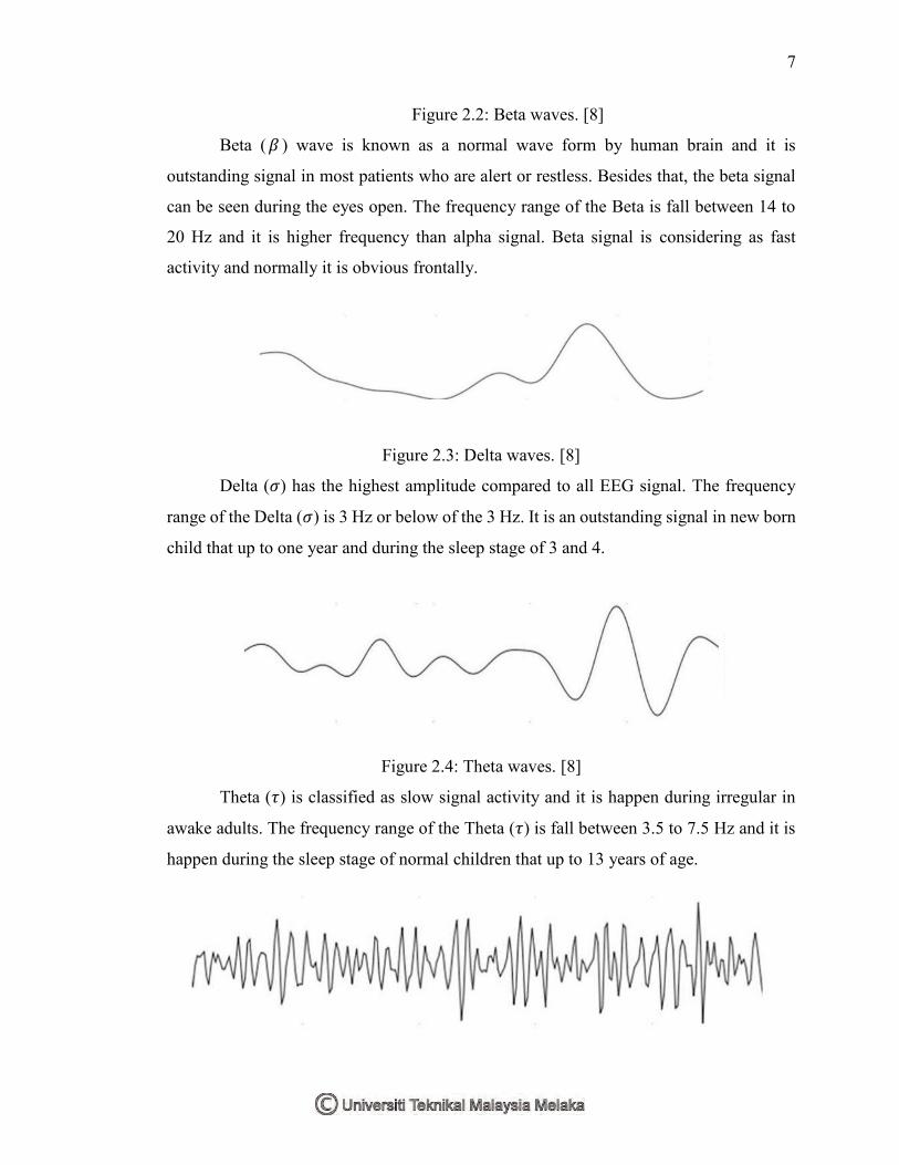
Figure 2.2: Beta waves. [8]
Beta (𝛽 ) wave is known as a normal wave form by human brain and it is
outstanding signal in most patients who are alert or restless. Besides that, the beta signal
can be seen during the eyes open. The frequency range of the Beta is fall between 14 to
20 Hz and it is higher frequency than alpha signal. Beta signal is considering as fast
activity and normally it is obvious frontally.
Figure 2.3: Delta waves. [8]
Delta (𝜎) has the highest amplitude compared to all EEG signal. The frequency
range of the Delta (𝜎) is 3 Hz or below of the 3 Hz. It is an outstanding signal in new born
child that up to one year and during the sleep stage of 3 and 4.
Figure 2.4: Theta waves. [8]
Theta (𝜏) is classified as slow signal activity and it is happen during irregular in
awake adults. The frequency range of the Theta (𝜏) is fall between 3.5 to 7.5 Hz and it is
happen during the sleep stage of normal children that up to 13 years of age.

8
Figure 2.5: Gamma waves. [8]
Gamma ( 𝛾 ) is often classify as a distinct class by many researcher of
Electroencephalogram and include the Gamma (𝛾 ) signal in beta brain signal. The
frequency range of the Gamma (𝛾) is associated between 40 Hz and 70 Hz. The Gamma
(𝛾) normally happen during perception and consciousness of human [9].
2.3 Brain Computer Interface (BCI)
In 1964 which is the first Brain-Computer interfacing system was described by Dr.
Grey Walter. On that time, Dr. Grey Walter had constructed an experiment on patient’s
brain which the patient actually undergoing some surgery for another reason. Some
electrodes were connected directly to the specific part of the patient’s brain. Dr. Grey had
asked the patient to press a button to advance slide projector and at the same time he start
to record the data of the patient’s brain. In the result, Dr. Grey Walter founded that the
patient can control the system without any movement after he introduced a delay from the
detection of the brain activity. This actually is the first Brain Computer Interface [10].
Generally, Brain-Computer Interface (BCI) is a system that measures brain
activity and converts the measured activity into artificial output that replaces, restores,
enhances, supplements, or improves natural output and thereby changes the output
interaction between the computer system and its external or internal environment [11]. A
Brain-Computer interface system must have four components. There are:
a. It must directly record the activity from human’s brain by using some
specific component.
b. It must provide feedback to the user
c. It must run in real-time.
d. It must rely on intentional control.
The BCI offers different ways for communication and control. This is an artificial system
that bypasses the human body’s normal translation pathways, which are the
neuromuscular output channels. The BCI system is directly measures the brain signal and
translates the measured signal into corresponding control signal for specific applications.