eeeeeeeeee - defense technical information center · project. task hamilton ... the trigger spacer...
TRANSCRIPT

D-A14i 344 DEVELOPMENT OF LOWER COST TRIGGER SPACER FOR M577 FUZE i/i(U) HAMILTON TECHNOLOGY INC LRNCRSTER PA
JYOO ET RL- APR 84 ARLCD-CR-84008 DAK@-S8-C-0283INCLRSFED F/ 0/i NL
EEEEEEEEEE

&j.
Kin
Al
''" IIIIN OI~l IL1125 .lA 1.6
MICROCOPY RESOLUTION TEST CHART
NL B
O N
'III-"IJ

. . . . - .. .
ADC
AD-E40o 156
__ TECHNICAL REPORT ARLCD-CR-84008
- I
- l DEVELOPMENT OF LOWER COST TRIGGER SPACERFOR M577 FUZE
JOHN C. YOO
HAMILTON TECHNOLOGY. INC.P.O. BOX 4787
LANCASTER. PA 17604
APRIL 1984
U.S. ARM RESEARCH AND DEVELOPMENT CENTERRIS GAmE w"A SYTnS LAISRTIR
-me, 0 JEW
APPROVED FOR PUBLIC RELEASE; DISTRIBUTION UNLIMITEDD:TIC
CD LEFCTE
84 05 07 004
", o.4 . ° . . . . .,
%" . -. . . . . . , .' .. . . ' .% " .- . . . ' .. . . " , . . . . , . , '. . . . ' - . . -. ' . . . ,. . '. ' .- . .'- - -,4,-- -*7-,"4. , " .
The views, opinions, and/or findings contained inthis report are those of the author(s) and shouldnot be construed as an official Department of theArmy position, policy, or decision, unless sodesignated by other documentation.
The citation in this report of the names ofcommercial firms or commercially availableproducts or services does not constitute officialendorsement by or approval of the U.S.Government.
Destroy this report when no longer needed. Donot return to the originator.I. 1 2 I
[ .°
|So.
----
ThSiwoiinado idnscnandi

UNCLASS I FI ED
S11CURITY CLASSIFICATION OF T1TFS PAG§ff(3SW Due..EawrE__
REPORT DOCUMENTATION PAGE BEFORE COMPLETIN. REPORT NUMIER 2. GOVT ACCESSION NO. 3. RECIPIENT*S CATALOG NUM9ER
'
,. ~Contractor Report ARLCD-CR-84008 A qc~4. TITLEI (aid ,Subet~le) S. YPE[ OFr REPORT &Pl[EOO COVERED[
DEVELOPMENT OF LOWER COST FinalTRIGGER SPACER FOR M577 FUZE Dec. 1980 - Sept. 1982
. ~6. PE[RFORqMING O00G. RElPORqT NUMBER[I
7. AUT4OR(a) S. CONTRACT OR GRANT NUMBER(&)
John C. Yoo DAAKIO-80-C-0203
9. PERFORMING ORGANIzATION NAME ANO AD RESS 10. PROGRAM ELEMENT. PROJECT. TASK
Hamilton Technology, Inc. AREA & WOR, UNIT NUUESP.O. Box 4787 Task #3Lancaster, PA 17604
11. CONTROLLING OFFICE NAME ANO ADORESS 12. REPORT OATE
ARDC, TSD April 1984STINFO Div (DRSMC-TSS) 13. NUMuEROF PAGS
Dover, NJ 07801 8210. MONITORING AGENCY NAME S AOOR9ESS(fl d1ifore nt *Mu ai Mi Ofilce) IS. SECURITY CLASS. (of tale reuov)
ARDC, LCWSL UnclassifiedNuclear and Fuze Div (DRSMC-LCN-T)Dover, NJ 07801 SON Ut
16. DISTRIBUTION STATEMENT (of We. R41-1')
Approved for public release; distribution unlimited.
17. DISTRIBUTION STATEMENT (of the .abeit enteed in Stock 0 l dlwift' ow Repo")
10. SUPPLEMENTARY NOTES
Thomas W. Perkins is the ARDC Project Engineer for this project. j,.l
It. KEY WOROS (Coad... an revern ade it mi noe. md! #dm- Or by blck mmber)
Trigger assemblyPolyphenylene sulfide (PPS) materialM577 fuze
20. ASSTRACT (Centuime do revers side it neaeeemy' and Idty by We* namb..)
The objective of this task was to reduce the cost of the trigger spacerassembly by changing material and simplifying fabrication processes. A newmaterial, polyphenylene sulfide, 40% glass reinforced, replaced the currentdie cast aluminum. The trigger spacer assembly was made using the injection
* molding process with the spacer pins inserted during the molding process.The secondary and assembly operations required on the aluminum spacer wereeliminated.
DO , 147. 3 - -@NP'UNCLASSIFIED p.SECURITY CLASSIFICATION OF THIS PAGE (Whem D0 EneW"e
CONTENTS
Page
INTRODUCTION 1
SUMMARY OF ACCOMPLISHMENTS 2
CONCLUSIONS AND RECOMMENDATIONS 3
TECHNICAL DISCUSSION 4
INTRODUCTION 4
THEORETICAL ASPECTS 6
FABRICATION 39
TESTING 40
INTRODUCTION Accessio For40
STATIC TEST NTIS GRA&I 41
FUNCTIONAL TEST Unannounced 48FUNTINA TEST: , USt if icati 0 o
30,000 RPM SPIN TEST 49
AIR-GUN TEST Distribution/ 50
BALLISTIC TEST Availability Codes 51: BALISTICTEST Avail andl/or,
COST AND WEIGHT Dit Seil55
COST 55
WEIGHT 56
APPENDIXES
A CHANGES AND MODIFICATIONS MADE IN TRIGGER ASSEMBLY 57
B PROPOSED TRIGGER SPACER DRAWING 61
C CHANGES AND MODIFICATIONS MADE IN TRIGGER SPACER 65
D PROPOSED SPACER PIN DRAWING 71
E MODIFIED SAFETY PLATE SHAFT DRAWING 75
F MODIFIED TOP PLATE DRAWING 79
G WEIGHT AND MASS OF TRIGGER PARTS 83
H CALCULATION OF w AND a 87
DISTRIBUTION LIST 91
_,_

I. INTRODUCTION
This report describes the work accomplished by Hamilton Technology,
Inc. for ARRADCOM under Task No. 3 of Contract *DAAK1O-80-C-0203 from
December 1980 through August 1982.
The objective of this task was to reduce the cost of the Trigger Spacer
S.* Assembly by changing material and simplifying fabrication processes,
and eliminating the need to assemble the locating pins.
The current Trigger Spacer is produced in three processes. First, a
blank Trigger Spacer is made as an aluminum die casting. Second, the
blank Spacer is machined to produce the axial holes and final
configuration. Then the top and bottom Spacer Pins are inserted to the
machined Trigger Spacer. Various materials and fabrication processes
were considered in this task to reduce the cost without degrading the
performance of the Trigger Assembly.
This report contains six sections and appendixes. This Introduction is
followed by Sum ary of Accomplishments (Section II), Conclusions and
" Recommendations (Section III), Technical Discussion (Section IV),
Testing (Section V), Cost and Weight (Section VI), and Appendixes. The
theoretical and fabrication aspects of the proposed design are
discussed in Section IV, and the descriptions and results of the
various tests are shown in Section V. The Appendixes contain the
changes and modifications made in the proposed design, drawings of the
proposed Trigger Parts, weight and mass of trigger parts, calculations
of angular velocity and angular acceleration, and the firing reports.
°1
• o•-.I . % • - , °.-• . ••, . . . - . . • . . . . .

11. SUMMARY OF ACCOMPLISHIMENTSI' .
A now material - polyphenylene sulfide, (PPS, 40% glass reinforced) was
selected, and Trigger Spacers were made from the new material by injec-
.' tion molding with Spacer Pins inserted during molding. This plastic,
110% reinforced material was selected because of its high strength and
dimensional stability. PPS possesses outstanding chemical resistance
and thermal stability because of its crystalline structure.
The fabrication processes have been simplified because the injection
molded Trigger Spacers do not require secondary machining operations
and the process of assembling Spacer Pins. The new design of attaching
the 1DF to the three-module assembly (Contrazt No. DAAK10-79-C-0169,
* Task No. 2) has been accommodated in this task.
The theoretical aspects and fabrication processes were studied, and PPS
Trigger Spacers were assembled. The PPS Trigger Assembly was subjected
to a vigorous test program which included successful Ballistic testing
in all standard tubes, static compressive loadings, airgun (30,000 g),
spin tests (30,000 RPM), and accelerated aging tests such as thermal
shook, chemical compatibility and temperature and humidity testing.
The theory and the test results indicate that this PPS Trigger Spacer
did function properly and safely under the design requirements of
30,000 g acceleration with a 30,000 RPM spin, and will survive long-
term storage.
A cost reduction of $0.8799 per fuse has been projected from this task.
2
. .. . -.._-. . . . _ -.. .. . ' 7 U" "_. . r . . - -'; " " ' - "J
III. CONCLUSIONS AND RECOMMENDATIONSa.,'.,
The 40% glass reinforced PPS Trigger Assembly was subjected to a series
of ballistic, air-gun and spin tests and various accelerated aging
tests with successful results. The theory which was confirmed by the
results verifies that the PPS Trigger Assembly will function properly
and safely at 30,000-g acceleration, with 30,000-RPM spin design
envelope.
Based upon the successful test program ahd the projected cost savings
of $0.8799 per unit, this PPS Trigger Assembly is recommended for
incorporation in the M577, MTSQ Fuze Technical Data Package.
1
a'3
4,.
a.
-a *
qa* •

IV. TECHNICAL DISCUSSION
A. Introduction
This section describes a feasibility study performed on the pro-
posed material - polyphenylene sulfide (PPS, 40% glass
reinforced).
A new material - polyphenylene sulfide, (PPS, 40% glass
reinforced) was selected, and Trigger Spacers were made from the
new material by injection molding with Spacer Pins inserted during
molding. PPS (40% glass reinforced) was selected because of its
high strength and dimensional stability. PPS is a high-strength
thermo-plastic which has outstanding chemical resistance and ther-
mal stability because of its crystalline structure. PPS requires
a processing temperature of 600°F to 6750 F for molding, and the
resin has no known solvent below 4000F. The resin is inert to
most organic solvent and aqueous inorganic salts over a wide tem-
perature range.
Primary engineering applications for the injection molding PPS
resins are mechanical and electrical-electronic equipments. The
mechanical uses for PPS resins include gears, cams, pistons,
bearings and such processing equipment applications as
submersible, centrifugal, vane and gear-type pumps, where mechani-
cal strength, high temperature stability and chemical resistance
are needed.
There are military (ML-P-46174) and ASTh (ASTM D-3646) speCifica-
tions which define the material properties and requirements of the
glass-reinforced PPS. In addition to MIL-P-4617T4, the following
4

4V-
iS a list of additional military specifications covering various
applications of molded polyphenylene sulfide, glass fiber rein-
forced products:
a. MIL-C-28754
b. MIL-C-55302
c. MIL-C-83513
d. MIL-C-83734
e. MIL-S-83502
f. MIL-S-83505
Currently, the Insulator Spacer (ARRADCOM Dwg. No. 9327315), which
was made from PPS (40% glass reinforced) by the injection molding
process, is being used in the 105,., M456 Heat Cartridge.
*! This section contains three subsections. This Introduction is
followed by Section IV-B (Theoretical Aspects) which contains
discussions concerning mechanical properties, creep, aging, andI.,
chemical compatibility characteristics of PPS. The shear stress
on the Spacer Pins due to the angular acceleration has been also
-3. analyzed in this section. Section IV-C (Fabrication) discusses
the fabrication aspect of the proposed Trigger Assembly.
Several minor changes were made to the Trigger Assembly because of
the changes in material and fabrication process. The load bearing
area of the Trigger Spacer was increased to increase the margin of
operability of the proposed Trigger Spacer. The top pivot hole of
the Safety Plate Shaft was changed to a clearance hole, and the
pivot hole was moved to the Top Plate. Consequently, the length
of the Safety Plate Shaft was increased. The Spacer Pins were
redesigned to contain grooves so that the insert molded pins can
5

withstand the unseating load requirement, and the lengths of the
top and bottom Spacer Pins were changed to the same length. These
changes are discussed in Section IV-B.
Additional changes have been made to the Trigger Spacer, and they
are discussed in Section V-B-l (increased Trigger Spacer height)
and Appendix C-5 (new method of attaching HDF). The detailed
descriptions of changes and modifications are shown in Appendixes
V A and C, and the drawings are shown in Appendixes B, D, E and F.
B. Theoretical Aspects
The major areas of concern in the Trigger Spacer material substi-
tution to polyphenylene sulfide (PPS, 40% glass reinforced) are
'-. strength and rigidity. Other important areas of concern are its
long-term mechanical properties (creep, aging, and chemical
compatibility) and fabrication properties (insert molding and
staking capabilities). These subjects are discussed in this sec-
tion.
1. Stress of the Trigger Spacer due to 30,O00-g Acceleration
The Trigger Spacer is required to withstand the force due to
30,000-g acceleration of the Timing Scroll Assembly (less
Mainspring Barrel), Top Plate and Trigger Spacer at the
instant the projectile is fired. Since the compressive
strength of PPS (21,000 psi)1 is considerably lower than the
die-cast aluminum (46,000 psi)2 , the compressive stress on
the Trigger Spw-er has been studied.
1. "Property Chart," Modern P Ast' s Encyclopedia (McGraw-Hill Publication),
Vol. 56, No. IOA (1979-80). '. 516.
2. "Note 2," ARRADCOM Drawing No. 9236605, P. 2.
6
" -P" ":":" •-.-. ... .. .-- ." "-*"-""- ."*. . - - "-.. ... .- '-. .--- "- .... .''-'-.-' ':',. ,'-

The stress on the Trigger Spacer can be calculated using the
following standard stress formula:
a P/A
where a is the compressive stress on the Trigger Spacer
%!. in psi
P is the force due to 30,000-g acceleration of the
Timing Scroll Assembly (less Iinspring Barrel),
Top Plate and Trigger Spacer in lbs.
A is the area of the Trigger Spacer being com-
pressed against the Bottom Plate in inch2
The approximate area (A - 0.320 inch2 ) was obtained from a
sketch drawing because of the dimensional complexity.
To compare the stress on the aluminum and PPS Trigger Spacer,
the compressive stress on the aluminum Trigger Spacer was
calculated as follows:
=Pa ma 2 (wa/g)(3°,o0o g) = 30,000 Wa
= 30,000 (0.0758 + 0.0328 + 0.0625), (See Appendix G)
= 5,133 lbs.
aa = Pa/A = 5,133/0.320
z 16,000 psi
Now, the compressive stress on the PPS Trigger Spacer with
the same configuration as the aluminum spacer was found as
shown below.
Pp ma = (Wp/g)(30,000 g) a 30,000 Wp
= 30,000 (0.0758 + 0.0328 + 0.0418), (See Appendix G)
z 4,512 lbs.
7
- V- TV
2. Deformation of the Trigger Spacer under 1,000 lbs.
Compressive Load
The Trigger Assembly is required (in Drawing #9236603) to
function properly at 2,000-RPM spin when the Trigger Assembly
is loaded with 600 to 1,000 lbs. in compression. For the
% Trigger Assembly to function properly, the Trigger Spacer
should not deform more than the minimum endshake allowed
(0.003 inches) between the two trigger plates and the Firing
Arm Shaft under 1,000 lbs. compressive loading. Because of
the complex Trigger Spacer shape and the lack of Young's
Modulus data on PPS, the deformation of the Trigger Spacer
under 1,000 lbs. was calculated approximately as shown below.
c ( C/Y.M.)
where 6 = deformation in inches
e = strain in inch/inch
-a spacer height = 0.540 inches
a z stress due to 1,000 lbs. in psi
Y.M. Y Young's Modulus in psi
Since the Young's Modulus in compression is not known, the
Y.M. in tension (1.7 x 10⁶ psi) was used in the following
S.. calculation. 1
1. "Property Chart," Modern Plastics Encyclopedia (McGraw-Hill publication),
Vol. 56, No. 10A (1979-80), P. 516.
8
Q .. .-o-. . .. . . . . .-.... .o - . .. ..... .. . .... ... ..... ; .? . . . . .. . . . .S..,,"",, ;' ; ', ."•,, , , ", . -, ,", , - .. _. ' ., . ., :,. ,.." ,.,. ,, " ,,.,. " " "" ' . . ,,.' -""
".,d
op = Pp/k 4 q,512/0.320
14 lq,000 psi
The above calculations show that the margin of operability of
the PPS spacer (margin of operability z material strength/
maxiu m stress expected = 21,000/14,000 = 1.5) is lower than
the margin of operability of the aluminum spacer (margin of
operability z 46,000/16,000 = 2.9).
Although the expected compressive stress on the PPS Trigger
Spacer is lower than the material strength, the design change
of increasing the bearing area was made to increase the
margin of operability.
By modifying the Trigger Spacer dimensions (see Appendix
C-2), the bearing area was increased from 0.320 inch2 to
0.530 inch2 . The following stress calculation was made,
based on this increased area.
up z Pp/A x 4,512/0.530
V'I = 8,513 psi
The margin of operability based on the increased bearing area
was calculated to be 2.5.
Now, the expected compressive stress on the PPS Trigger
Spacer is about 40% of the material strength, and the margin
of operability of the PPS spacer (2.5) is comparable to the
margin of operability of the aluminum spacer (2.9).
9
*16
aUP/h1,000/0.530
= 1,900 psi
_,_ z o/Y.M.).-I
* (1,900/1.7 x 106)(0.540)
- 0.001 inch
The calculation shows that the expected deformation (0.001
.inch) is less than the minimum endshake allowed (0.003 inch),
and this indicates that the Trigger Spacer made from PPS will
function properly under 1,000 lbs. compressive load.
- 3. Stress of Pivot Holes Due to 30,000-RPM Spin'a
The Trigger Spacer shall not deform at the pivot holes of
the trigger shafts under 30,000-RPM spin. The compressive
loads will be applied to the pivot holes due to the tangen-
tial and normal forces of the trigger shaft assemblies when
the projectile is fired.
The compressive stress in the Release Lever Pivot hole, which
is the most severely stressed area, has been calculated as
V4, shown below. Note that the pivot holes of the Firing Arm4o
Shaft and Safety Plate Shaft (see Section IV-A-5-h) are in
the plates.
a 2 F/A z (Fn + Ft)/A
10
* ~where a a stress in psi
F a combined force in lbs.
A = bearing area in inch 2
Fn a normal force due to 30,000-RPM spin in lbs.
Ft z tangential force due to angular acceleration in
lbs.
The normal force (Fn) and the tangential force (Ft) can be
found as follows:
Fn a irw 2
Ft a mra'Iwhere m = the maw of the Release Assembly (0.0000497 slug)
r 2 the center distance between the pivot hole and
the spin axis (0.039 ft.)
w z the angular velocity (3141.6 rad/sec) - See
Appendix H
a z the angular acceleration (1,545,600 rad/sec2 ) -
See Appendix H
Assuming the worst Case, which is the maximum angular accel-
eration occurs at the maximum angular velocity, the normal
and tangential forces can be added as shown below.
F aPn Ft
F X \f + Ft2
/(wi', 2)2 * (m, a )2
W V- 11
'.- S,. *',, ;,-.'.',',~.- .. •, . . -.. .-. -.. ...*. -. . -* . . . .

.
Nov, substituting the values into the equations
z (0.0000197)(0.039) (3111.6)1 . (1515600)2
2 19.1 lbs.
The beaing area (A) can be found from the minimum shaft
pivot diameter (D) and the Wnimum contact length (L).
A 2 D • L a D(.in. pivot length - max. ohamfer length - max.
.4 endshake)
= (0.060)(0.087 - 0.042 - 0.009)
a 0.00216 inch2
.'. . Then, the maumim expected stress at the Release Shaft Pivot
hole can be found.
o = 7&/
x 19.11/0.00216
a 9,000 psi
The calculated stress (a z 9,000 psi) is about 43% of the
material strength, and the margin of operability is about
2.3. Note that the actual stress will be less than the
calculated stress because the force (F x 19.14 lbs.) will act
at the bottom pivot hole as well as at the top pivot hole.
11. Stress of Spacer Pins Due to the Angular Acceleration
The top and bottom Locating Spacer Pins will be loaded in
shear due to the angular acceleration when the projectile is
12
:" 4 -- '.".. i : i ;, ,"/ . . i:" / ";i : "; : ' ... . , .. ,a,,.,..,.,-,.,,.'..,:. , '.. . . ... - . '. .o". -" ,/ " '" '. ". ". " -'>,..'V . "'' -

fired. Some of the shear load may be borne by the screws
holding the Trigger Assembly to the sleeve; however, it is
assumed that the entire shear load is on the Spacer pins.
Only the stress of the top Locating Spacer Pin was calculated
because the higher load will be applied to the top Locating
Spacer Pin.
i T x=FK
where T a the torque in inch • lbs.
F = the force created due to the angular acceleration
of the Trigger and SSD Assembly in lbs., and
F = m(K/12) a-. 5%
*: V K : the radius of gyration in inches, and
K ./ ( fr.dm)/( 'fdm)
m the mass of the combined Trigger and SSD Assembly
in slugs
a z the angular cceleration in rad/seo2 , and
o.a 2 1,545,600 (See Appendix H)
/ r z the distance of dm from the center of rotation in
inches
dm z the infinitesimal mass in the combined Trigger and
SSD Assembly in slugs
and
T Rd
,; 1
5' *o . ° . . . - • . - . . . . .. ... . . .

* '..-.,--
where R s the reaction force of the top Spacer Pins in lbs.d u the distance of the top Spacer Pins from the center
of rotation in inches, and d z 0.725 (See Appen-
dix B)
Now, the reaction force (R) can be found as follows:
T x FK z Rd
or
R = (FK)/d
= ((e(K/12) a )K)/d
. (inK2 c )/(12d)
From Appendix G,
mass of PPS Trigger Assembly z 0.0034938 slugs
mass of SSD Assembly a 0.0023168 slugs
and the total mass (m) a 0.0031938 + 0.0023168
a 0.0058106 slugs
Substituting values,
yR = (inK2 aVO)/12d
= ((0.0058106)K2 (1,545,600))/((12)(0.725))
z 1032K2
Now, the value of the radius of gyration should be found from
the equation K f v/( Ir 2dm)/( 1dm) to find the reaction (R).
14
-S.:":' ':..,:''' ... '"" -.. ,I'' .' - - . . - - . "" ' ''''' .... '':... ' ..... , - ' ....- '; ,...
* . ... .'. . - . . i,~ im ir ~ l, l ,ilm ,, , r4 a m
]$~i u l ,,m,,k , ,,m

The approximate value of K has been calculated, because of
the complexity, as shown below.
K z V(i -rdm)/ (f dm)
assuming uniform thickness (t) and density (P)
a /( r2 P tdA)/( fP tdA)
z .A P t r r2 dA) /( P tf dA)
" a x4( 1 r2dA)/( f d A)x-- JTI
where J = the polar moment of inertia of the combined
Trigger and SSD Assembly in inch1
A 2 the cross-sectional area of the combined Trigger
and SSD Assembly in inch2
Assuming the Trigger and SSD Assembly is a cylinder,
J = w D4l/32
A rD2/11
where D x the diameter of the Trigger Spacer in inches, and
I" D a 1.615 (See Appendix B).
Then
~~~~itw/D D1 /3)(w 2 11
3 /(1.645)2/8
a 0.582 inch
15
. ... . " . .. • •. ". "'..-. . " "" " . .".'- ... .'. ..'.-.. - . .. '. - - - "-..._ '.' ." ,, **V**P***;*"..."' "" ".*'"."."'*.""". "*"" " " :.- *,* *-.,.-.,',** *:* -J -*' ,*', v . ...." ." -"-

Now, the reaction force R) can be found with this approxi-
Hate value of radius of gyration (K = 0.582).
R = 1032K 2
z (1032)(0.582)2
:350 lbs.
And the stress of the top Spacer Pin can be calculated as
shown below.
a = R/(2Ap)
where a = the shear stress of the top Spacer Pin in psi
R = the reaction force in ls., and R z 350
Ap a the cross-sectional area of the Spacer Pin in
a. inch2 , and Ap = r Dp2/I a i (0.0932)2/4
x 0.0068 (See Appendix D).
Substituting the values,
a = R/(2Ap)
= 350/((2)(0.0068))
z 26,000 psi
This calculated stress (a = 26,000 psi) is about 39% of the
minimm material strength specified on the Spacer Pin drawing
- ppendix D - based on the heat treating of 313 Knoop
Hardness ( 120,000 psi tensile = 66,000 psi shear
strength). The morin of operability is about 2.6.
16
1 ' 6 A*n* *z* ~ ** * *
m41,"q . . o o , , . ° . . w t. - . " . . : -
5 C. Creep
It is known that plastics creep under a continuous sustained
load. There are three places in the Trigger Spacer where a
continuous sustained load is applied. They are the Safety
Plate top pivot hole, Firing Pin side wall, and Torsion
Spring arm slot.
a. Force in the Safety Plate Top Pivot Hole
The top pivot hole of the Safety Plate Shaft is loaded
- . in compression due to the load exerted from the Firing
Pin Spring.
From the "spring data - 9.0 lbs. max. at 0.36 inch and
the free length (0.64 inch)" shown in Drawing #9236624
and from the calculated minimum spring length (0.2904...
inch) when compressed, the maximum spring load can be
found as shown below.
K z P/6
where K z spring constant in lbs./inch
. P z spring load in lbs.
.[ 6 x deformation in inches
Then,
. K a P/6 a PI/(L - LI) a Pm/(L - Lm)
17
_. . . . . 4. .p 4 * - -i %44444444444-4-,4,. " .. ... . . . .. . . %. ... .... .. ,,..,,. .. ,.,, .-. ,, , ,,,.. C, ,, ,'j . . ... ,

"4,.
where P1 x 9 lbs.
L z 0.64 inch
l a 0.36 inch
Pm x maximum spring load
La a 0.29 inch
Substituting the corresponding values, the mximum
spring load (Pm) am be found as follows:
P1/(L - L1) 2 P./(L - La)
or
Pm x P1 (L - Lm)/(L - Li)
* 9(0.641 - 0.29)/(0.641 - 0.36)
a 11.25 lbs.
Now the compressive load at the top pivot hole can be
found as follows.
From the force diagram shown below, the force, -p, which
induces the compressive load at the top pivot hole can
be found.
-RP ft a ft s 11.25 lbs.
2C - Rp zf tan 20
, a Pm tan 20
7 e ( 11.2?5) (0.364)
P z.1
.4 ,'I,' I.I '.,. ''"''" "" ".,' ", ". ". . '.". ". ". ". ".Pm -a 1. lb. -°%- %. . .
,4, . • _ 3.. . _, . - - . % " "- .,m,:..",,, ,,,. ._ +
The force, Rp, is applied to the Safety Plate Assembly,
causing reactions at the top and bottom pivot holes and
at the point where the Safety Plate contacts the Firing
Arm Shaft. The force, Rz, is applied to the Safety
Plate Assembly, causing reactions at the top and bottom
pivot holes and at the shoulder of the Safety Plate
,-p Shaft (see Figures 1, 2 and 3).
-
FIRING PIN
a 2161
FIOUPR 1. Feorce Ahalysis lgran' (Due to Rp) -0Ola 2
; . b • 0.2161~~ - .26 a(tan a2 .11-OOltz 2
"" • 0.1967
Jt o a 0.11002 -f a 0.11002 - O.095(eos 59)PIT= 0.3513
da0.01109 ., 0.095(sin 59)
.O - T~.. a 2 le (320 and 590) and the dimension "a" were measured
SHF
WhO a a 1 - layout a..
a 0-196
a 04,
0.35.13
d. a .40 .053i 9

.,
i8
-Hbx)a,(Hbv)z- 060 ;033° - .
065
031 ""--01967 120
.P, .(
4..\ Figure 2. Force Analysia Diagra (Due to Ri)
Where m a 0.120 * (0.060 + 0.016)/2
a 0.173
NOTE: Nix a iZY RZ, and B 2 IZ
.20
4.4
-- L0
, ,. , ... . .,, . , . . . . .'1'''"- . , ,", .", ." ,",', ," .' ' " -. '''' ,,,.,.., , " . . .. ".-"..". . . ". - ' , ..'. " . ,"., .. . , , . ,- ' -, .
444 " o °
e ° ," o
"
(Hbx)I1,(Hby) 1 0601 3
It
. - - -- 065
'S
g.:.:-: --"! "----- ,---- (Ht i,, ,(H y)i 6 -
044it
Figure 3. Force Amalysis Diagram (Due to Si and Sy)
Where m x 0.120 + (0.060 + 0.016)/2
a 0.173n z a - 0.033 - (0.060 + 0.065)/2
a 0.0775
21-
", I
-;U.
...',
N2
From the force diagram shown in Figure 1, the reaction
forces of the Safety Plate Shaft due to Rp can be found.
+
E Fx -0 - -Rpx + FX + Sx
-RP(cos 32) + Fx + Sx
-l.1(cos 32) + Fx + Sx
-3.418 + Fx + Sx
• Fy 0 2 -Rpy + Fy + Sy
-Rp(sin 32) + Fy + Sy
= .1(sin 32) + Fy + Sy
z -2.17 + Fy + Sy
E Ms 0 a -Rpx(b) - Rpy(a) + Fx(d) + Fy(c)
= -3.48(0.1967) - 2.17(0.031) + Fx(0.1223)
+ Fy(0.3513)
= -0.685 - 0.067 + 0.1223Fx + 0.3513Fy
From the geometry of Fx and Fy,
--- Fx/FY a tan 59 = 1.66143
-.. .-
or
Fy z 1.66143Fx
Substituting 1.6643Fx for Fy in the moment equation,
S.' E Ms = 0 = -0.685 + 0.067 + 0.1223Fx + 0.3513Fy
= -0.752 + 0.1223Fx + 0.3513(1.6643Fx)
= -0.752 + 0.1223Fx + 0.5847Fx
. -0.752 + 0.707Fx
4. 22'q1*
k I I . -+ I l . . .l. ... ,+l + J l • d,• lt ,
Therefore,
Fx = 0.752/0.707
z 1.06 lbs.
Fy x 1.6643Fx z 1.6643(1.06)
= 1.76 lbs.
Sx = 3.48 - Fx = 3.48 - 1.06
. 2.42 lbs.
Sy = 2.17 - Fy x 2.17 - 1.76
x 0.11 lbs.
The forces Sx and Sy are applied to the Safety Plate
Shaft as shown in Figure 3, and the reactions at the top
.:pivot hole, due to the forces Sx and Sy, can be found as
follows:
From the diagram shown in Figure 3,.
Mbx = 0 f -Sx(m - n) . (.Htx)l(m)
= -2.42(0.173 - 0.0775) (Htx)1(0.173)
-0.231 + 0.173(Htx)1
or (Htx)1 = 1.31 lbs.
" Mby = 0 = -Sy(m - n) + (Hty)1 (m)
-0.41(0.173 - 0.0775) + (Hty)1(0.173)
-0.039 + 0.173(Hty)1
or (Hty)1 0.23 lbs.
23
.. ,' 0-'. ., ; .' ." . . .... . . . . . . .
Therefore, 1.34 lbs. (in X-axis) and 0.23 lbs. (in
Y-axis) are acting at the top pivot hole with the minus
(-) direction due to the reaction force Rp.
Now, the force acting at the top pivot hole, which is
created due to the reaction force Rz, can be found as
shown below.
As shown in Figure 2, since the moment arm of Rzy (0.31)
is smaller than the moment arm of B (0.165/2 = 0.0825),
no force is expected to be applied to the top pivot hole
in X-axis due to the reaction force Rz.
Then, (Hty)2 = 0 lbs.
V Mby = 0 = -Rzy(0.1967) + B(0.0825) + (Hty)2(m)
= -11.25(0.1967) + 11.25(0.0825) + (Hty)2(0.173)
z -1.285 + (0.173)(Hty)2
or (Hty)2 = 7.43 lbs.
Therefore, only the 7.43 lbs. is acting at the top pivot hole
in Y-axis with the plus (+) direction due to the reaction
force Rz.
To find the total force acting at the top pivot hole, the
force components acting at the top pivot hole due to Rp and
Rz have been added as shown below.+
Px z (Htx)1 + (Htx)2
= -1.3I4 + 0
= -1.34 lbs.
24
.r W, - q-1..
Py x (Hty) 1 + (Hty)2
'" a -0.23 + 7.43
a 7.20
'I., = v/(-1.34)2 + (7.20)2
* 7.32 lbs.
e = are tan (Py/Px)
* are tan (7.32/-1.34)
* -790 or 1010
Therefore, the 7.32 lbs. is acting at the top pivot hole
"4. with 1010 angle (or 110 from Y-axis) in compression as
shown in Figure 1.
b. Stress in the Top Pivot Hole
The compressive stress in the top pivot hole of the
Safety Plate Shaft can be found from the force Pxy (7.32
lbs.) and the bearing area in the hole.,,' .%
S :P/A
where a : compressive stress in the top pivot hole
.- ; in psi
P z Pxy a 7.20 lbs.
A = bearing area
z (min. shaft pivot dia.)(min. contact lgth.)
z (0.0597)(0.046)
a 0.0027 inch2
25
C..

Substituting the values into the equation,
ph = P/A
z 7.20/0.0027
= 2,700 psi
a. Force in the Torsion Spring Arm Slot
S.%
p.'5 The Torsion Spring arm slot in the Trigger Spacer is
loaded in compression due to the torque exerted from the
Torsion Spring.
From the "spring data - 0.15 inch - pound max. torque at
the final position when unloading" and from the spring
arm length shown in Drawing 9236610, the force applied
to the slot can be found as shown below.
F = T/L
where F 2 force applied to the slot in lbs.
T : 0.15 inch pounds
I : min. Torsion Spring arm length
= 0.14 + (0.42 - 0.111)/2
: 0.28 inch
Substituting the values into the equation,
~ z T/t
= 0.15/0.28
z 0.54 lbs.
-5 26
1-5
'A d. Stress in the Torsion Spring Arm Slot
The compressive stress in the Torsion Spring arm slot
can be found from the force (0.54 lbs.) and from the
bearing area in the slot.
F/A
C, "where F = 0.54 lbs.
A = bearing area in the slot
= (spring diameter)(contact length)
z (0.o19)(0.4 - 0.16)
= 0.0053 inch2
Substituting the values into the equation,
a F/A
= 0.54/0.0053
, 102 psi
e. Force on the Side Wall of the Firing Pin Hole
A The side wall of the Firing Pin hole is loaded in
compression due to the load exerted from the Firing Pin
. ~Spring and the reaction of the Safety Plate.
The force diagram has been constructed to find the
magnitude and the mode of the reaction (B) at the side
wall as shown on the following page.
i'2 z27
V..,
*d* i i -! I ~ !..i . . l .eI .
.'.P i q i "°
II W / ". i• . ..i .l1 .i Sq"t i • ~LIIiill

-,-..--_
4-..-.R.. .1295
Rp
470-.
0- .X '- .3 -7 o
. F--.187.. 4
From the force diagram shown above,
"- .0- m - fo, - n d Fx z aRp- B
or 1. a ft 11.25 (see Section IV-5)
4- ".' Rp a B 4 1.1 (see Section IV-5)
B .14a 0 x A + Pf (0.187/2) - ft (0.1295) Rp (0.370
- 0.180)
x - + (11.25)(0.187/2) - (11.25)(0.1295)
+.. I.1(0o370 - 0.180)
z -A e 0.3741
or
M 0.374 inch • petada
28
%" *. . ,. 4. \'. * . '_. "_. .-. ., ,,- •*.. . - .- . p- . ., -: . •., ., . .* ,.-. -4 *% * ~ '.* ,.* ..** % %"-, , ., ' 4.. ' , , .-
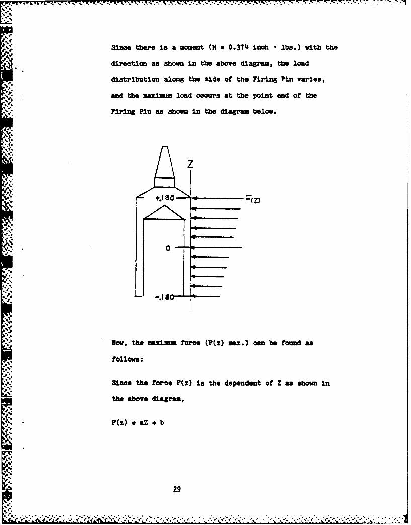
Since there is a moment (M z 0.374 inch * lbs.) with the
direction as shown in the above diagram, the load
distribution along the side of the Firing Pin varies,
and the maximum load occurs at the point end of the
Firing Pin as shown in the diagram below.
z
0--
Now, the inuiinm force (F(z) max.) can be found as
follows:
Since the force F(z) is the dependent of Z as shown in
the above diagram,
F(z) aZ b
5N29 29
_V.
v . .-. . -...- ,. . ;.**?*,, ;- " -. '" -'. '..:'<<- ,-- " ' " ..- '- ..-*.''.*. ." ".,--, ' .¢ ,.' " 2. ' "'2-2"- -' .-. " '-......:'-" . .. 5.,, ,Z

where "a" and "b" are constants, and "a" is the slope
-- 7 and "b" is the force at Z = 0.
and
+0.180Z Mo = " F(z) * Z • dz = M
-0.180
+0.180Z F F 7(z) •dZ B
-0.180
where F(z) = the force per unit length in lbs./inch.
Z = the position along the side of the Firing
Pin in inches
M: 0.374 inch • lbs.
B: 41.1 lbs.
Substituting "aZ . b" for F(z) into the moment and the
force equations,
+0.180E Mo = f F(z) • Z * dz
-0.180
I (aZ + b)Z • dz
- f (aZ2 + bZ)dz
z a fZ2dz + bf Zdz
z (a/3)Z3 + (b/2)Z2
z (a/3)((0.180)3 - (-0.180)3) + (b/2)((0.180)2
- (0.180)2)
2.
.f.4
-,V 30

- (a/3)(0011664)
, 0.003888a
z-" 0.374
Therefore, a z (0.374)/(0.003888)
= 96.2
+, +0.180F z I F(z)dz
-0. 180
x f(aZ + b)dz
x afZdz + bfdz
x (a/2)Z2 + bZ
x (a/2)((0.180)2 - (-0.180)2) + b((0.180) -(-0.180))
z b(0.360)
= 4.1
Therefore, b x (4.1)/(0.360)
a 11.14
Now, the maximum force occurs at z = 0.180,
F(z) max. z F(z z 0.180) a aZ + b
z (96.2)(0.180) + 11.4
- 28.72 lbs./inoh
f. Stress on the Side Wall of the Firing Pin Hole
The maxiinm force (F(z) max. z 28.72 lbs./inch) will be
applied to the side wall of the Firing Pin hole at the
31
.... .+o . ...... ........ ... **' -. .*". *'.° + . ' .-- a ' . ' '%-. . .. " '. ,"*.= b. " -.- , ,' * .' . . ,- , . , t

S. W. T. S. V. * -.
point where the pin-point end of the Firing Pin contacts
the side wall. Then, the maximum bearing stress at the
side wall can be calculated based on this maximum force
and the diameter of the Firing Pin as follows:
a max. F F(z) max./D
S-. where a max. = the maximum bearing stress in psi
. ~F(z) max. = 28.72 lbs./inch
D a the minimum Firing Pin diameter in inches
%.'.b*-and D = 0.187 (Dwg. #9236623)
Substituting the values,
a max. = F(z) max./D
28.72/0.187
s 154 psi
.. g. Creep Deformation
Since data concerning the creep deformation of PPS is
not available, the creep deformation of another high
strength plastic, Acetal (40% glass reinforced) was
calculated, based on the study results published in the
"Plastics Engineering" magazine shown as follows.1
1. J. R. Louglin, "A Now Creep Law for Plastics," Plastics Engineering, Feb.
1968, P. 97-103.
_32
S V.
,
",

- _- -
• " The article "A New Creep Law for Plastics" in the maga-
zine shows that the flexural creep of Acetal (110% glass
reinforced, tested with 11660 psi initial stress at 250C)
has the following creep characteristics:
Log(6.1075 - Log E) = -1.13812 + 0.196236 Log t
where t z time in hours
" E = pseudo - modulus of elasticity at time "t" in psi
,4- By substituting 175,200 hrs. (20 yrs.) for time "t" in
-'- the above equation, the pseudo-modulus of elasticity
after 20 years can be found as shown below.a.-
Log (6.1075 - Log E) = -1.13812 + 0.196236 Log 175200
4 aLog (6.1075 - Log E) z -0.1091498112
or
Log E = 6.1075 - 10- 0 .109 149842
x 5.329732
"-' -a Therefore,
E = 105.329732
z 2111,000 psi
Then, the creep deformation of the Safety Plate top
pivot hole, Firing Pin sidewall, and Torsion Spring arm
slot can be found from this pseudo-modulus of elasticity
33_, ""
a'-a

-!Z .- . ;- - --
(E = 214,000 psi) and the calculated stresses - 2,700
psi (for the top pivot hole), 102 psi (for the Torsion
Spring arm slot), and 154 psi (for the sidewall) as
shown below.
E - a/ = a/(6/ ) -- (a )/6
or
6 = (a •)/E
where 6 = creep deformation for 20 years in inches
a z stress at the area of concern in psi
= effective length in inches
E = 214,000 psi
To find the creep deformation, the effective length (2)
should be further obtained. However, the effective
- :.length (1), which will deform under the creep loading,
is not readily obtainable because of the dimensional
complexity. Therefore, the approximate effective
lengths (0.133 inch for the Top Pivot hole, 0.070 inch
for the Spring Arm Slot, and 0.8225 inch for the side
wall of the Firing Pin hole) have been used for the
following creep calculations.
34
* ~ .~~.i.-.: - ~ .:- ~ . . .*.... . *.*. *.-- -** -. : . .*:.*:- **

. . .. . 717 .17 . .t It.
Creep Deformation at the Top Pivot Hole of the Safety
Plate Shaft
-(2,700)(0.133)/2114,000
-0.0017 inch
A Creep Deformation at the Arm Slot of the Torsion Spring
6 a -* )/
-(102)(0.070)/2141,000
-0.00003 inch
Creep Deformation at the Side Wall of the Firing Pin
* Hole
* -z (15J4)(0-8225)/214,000
*~ - .0006 inch
h. Discussions of Creep Deformation
As noted, the above creep deformations were calculated
based on the creep characteristics of Acetal. Although
the creep characteristics of PPS inay be somewhat dif-
ferent from Acetal, the calculated creep deformations
were used as a guideline for the PPS Trigger Spacer
design modification.
43
Since the creep deformations at the arm slot of the
Torsion Spring and the side wall of the Firing Pin hole
are negligibly small (0.00003 and 0.0006 inch) and the
positions are not functionally critical, the creep
deformations have been accepted as tolerable.
Since the creep deformation at the 'Top Pivot hole
A(0.0017 inch) is, however, larger than the pivot hole
tolerance (0.001 inch) and the pivot hole is func-
tionally critical, the design change to avoid creep has
been made. By providing the Top Pivot hole at the Top
Plate instead of in the Trigger Spacer, the creep
problem in the Top Pivot hole has been avoided.
Becauje of this design change, the pivot hole in the
Trigger Spacer has been changed to a shaft clearance
hole, and the pivot hole has been added to the Top
Plate. Also, the Safety Plate Shaft length has been
increased.
The new drawings and change notes are shown in
Appendixes A-1, A-3, A-4, B, C-4, E and F.
6. Aging
Since PPS (40% glass reinforced) has been in existence for
less than ten (10) years, there is no actual data available
concerning the natural aging properties of PPS for twenty
36
-p' ' , '. .',, , ,I . . .-- ... ./ . . • . .. • . . . ." ".". . . " . . . . . . . . " . ..

(20) years. The natural aging properties were, therefore,
estimated from the thermal aging properties of PPS.
The thermal aging properties of PPS (40% glass reinforced)
were studied by Phillips Petroleum Company, and the results
of the studies are contained in "Report on Component -
Plastics." I The report shows that the PPS is expected to
retain at least one-half of its original tensile strength,
with the following temperature and time relation:
Log Y = 5320.6861 X - 5.4801723
where the test sample thickness 0.060 inch
Y = time in hours
X = 1/°Kelvin
Solving the above regression line equation for the points
with which we are concerned, the following results can be
A. obtained:
- 1. At 1650F, PPS takes 735,600 years to loose one-half of
its original tensile strength.-. '
2. For twenty (20) years, PPS retains one-half of its ori-
ginal strength at 4300F.
Extrapolating the 95% confidence lines, which are also shown
in the same report, PPS takes 4,500 years to lose one-half
1. "Report on Component - Plastics," Philips Petroleum Co., File E54700,
ProJect 73NK6336, December 11, 1973, P. 2 and P. II1-1B.
37
of its original tensile strength at 165 0F. Note that the
deviation gets larger as the extrapolating values get further
away from the actual test points, and that is why the 95%
confidence value (4,500 years) is significantly lower than
the regression line value (735,600 years).
"S Although the aging values (4,500 years and 735,600 years)
were not obtained from the test conducted at 165 0F, the esti-
mated values indicate that the decrease in strength of PPS
by natural aging is not perceivable in twenty years.
7. Chemical Compatibility
The PPS is known to have a hydrolytic stability at elevated
.temperatures, and also known to be chemically compatible with
a broad range of solvents, minerals, and organic acids and
alkalies.
' The Military Specification (MIL-P-46174) notes that "the
glass-reinforced polyphenylene sulfide is intended for use in
anti-friction gears, pistons, corrosion-resistant coating,
electronic components and bearing materials." The specifica-
Ction also notes that "there are no known solvents for PPS
below O000F, and PPS has excellent chemical resistance and
thermal stability."
Currently, there are six lubricants which have been approved%CC.
for use in the Trigger Assembly. They are Dow Corning 55M
38

• ."Grease (Part No. 9236521), mixture of Astro Oil and
Molybdenum Disulfide (Part No. 9236485), Instrument Grease
812 (Part No. 9236557), Nyogel 8113 (Part No. 9236606), Nyefilm
515 (Part No. 9236492) and Nye Astro Oil (Part No. 9236482).
PPS Trigger Spacers have been tested with satisfactory
results in Astro Oil, which is the main component of all
approved lubricants except Dow Corning 55M Grease.
C. Fabrication
The PPS Trigger Spacer Assemblies were made complete from the
I0 injection molding process, with the Spacer Pins inserted during
molding. No secondary machining operation or Spacer Pins assembly
process was needed.
* . However, the redesign of the Spacer Pins has been made to contain
grooves, so that the insert molded pins can withstand the axial
unseating load requirement (min. 25 lbs.). The new Spacer Pin
drawing is shown in Appendix D.
' ""During assembly, the PPS Trigger Spacers required no special
steps. The PPS Trigger Spacers were assembled with the trigger
parts according to the standard assembly procedure, and the
' staking and riveting operations were performed in the usual
manner on the current M577 Fuze production line.
39

* \-. .V. TESTING
A. Introduction
This section contains the descriptions and results of various
_. tests performed on the proposed Trigger Assembly.
Section B (Static Test) is consisted of four subsections - Static
Compression Test, Aging Test, Chemical Compatibility Test, and
Temperature and Humidity Test. The Functional, Spin, and Air-gun
tests are shown in Section C, D, and E accordingly. The Ballistic
Test is shown in Section F, and Section F also contains the Jolt
and Jumble, Rough Handling, and Transportation Vibration tests.
The height of the proposed Trigger Spacer was modified after the
Static Compression Test (Section V-B-l) to provide the required
end shake between the trigger shafts and the two plates. The
detailed description of this modification is shown in Appendix
C-3.
S40
~40
-)';'5.-'

B. Static Test
.1. Strength and Rigidity
A static compression test wa performed on the PPS Trigger
Assembly in a Tinius Olsen Eletuatic Universal Testing
Machine with a recorder and deflectometer * The load was
applied to the Trigger Assembly with the deflection rate of
1 less than 0.*100 inch per minute at the ambient temperature.
The 'load vs deformation" curv, at the PPS Trigger Assembly
was obtained from the test, and a typical *load vs
deformation" curve Is shown below.
z
44
. . . .
The load vs deformation curve shows that the ultimate
• . compressive strength of the assembled PPS Trigger Spacer is
over 10,000 lbs. As shown in Section IT-A-I, the force
induced from 30,000 g acceleration is 4,512 lbs., which is
about 45% of the ultimate compressive strength of the
assembled PPS Trigger Spacer. This agrees with the theoreti-
cal study result, which showed that the expected stress due
to 30,000 g acceleration is about 40% of the material
strength.
The load vs deformation curve also shows that the assembled
PPS Trigger Spacer deforms about 0.005 inches under 1,000
lbs. compressive load. This test result does not agree with
the theoretical study result, which showed that the PPS
. Trigger Assembly is expected to deform less than 0.001" under
1,000 lbs. compressive load.
* .~The difference between the test result (0.005 inches
deformation) and the study result (0.001 inches deformation)
*may have been caused by the non-uniform deformation of the
PPS spacer because of its uneven cross-sectional area.
Because of this excessive deformation, a design modification
was made to provide the minimm of 0.005 inches end shake
between the Firing Arm Shaft and the two trigger plates.
(See Appendix C-3.)
42
. *'
9..
2. Aging
a. Natural Aging
Two test samples made from PPS - 40% glass reinforced
material - (which was molded at least before 1975 with
the published material compressive strength of 21,000
psi) were tested in compression, and the results showed
an average compressive strength of 23,700 psi. We have
also received a compression test result showing an
average strength of 20,200 psi for the same material
from Phillips Chemical Company, who performed indepen-
dent testing recently.
The difference in the two test results y have been
caused by the difference in sample preparation method.
Both samples were made from a slab which contained a
textured surface, which had to be machined to avoid
stress concentrations. At Hamilton, only the textured
surface was machined and the other surface was not
machined to maintain the molded skin. At Phillips,
however, both surfaces were machined. It is, therefore,
understandable that Phillips' test result was lower than
Hamilton's test result.
As expected, comparing the two test results (23,700 psi
and 20,200 psi) with the published compressive strength
(21,000 psi), the decrease in compressive strength of
PPS material by the natural aging for seven years is not
4% evident.
43

b. Thermal Aging
Two PPS Spacers were submerged into water in a closed
jar and kept for 170 hours at 1650F. The weight and the
major dimensions specified in MIL-F-58983 (Rev. A) were
measured before and after the test. The test results
showed no discernable changes. The test results are
shown below.
Weight in Lbs.
Samplel Sampl 1 __________2_
NO Before After 1Charge fore After Ch e
Weight 0,0418 0.042J +0.48% 0,o0418 0.042( +0,48J
Height in Inches
Samle Sample 1 Saple 2No. Before After Change Befor After Change
Height 0.537 0.537 None 0-537 0-537 None
True Position in Inches: measured center-to-center distancebetween Datum -D- and the hole
Sample Sample 1 Sample 2No. Before After ghagge Before After h
SafetyHole 0.716 0.716 None 0.717 0.717 None
B ReleasHole 0.959 0.959 None 0.959 0.959 None
Diameter in Inches
Sample Sample 1 Sam le 2No. Before After Change Before After Change
SafetyHole 0.092 0.092 None 0.092 0.092 None
ReleasHole 0.063 0.063 None 0.063 0.063 None
- "44
~A : ' ~ , - : 1A! f *:O
3. Chemical Compatibility
A limited amount of chemical compatibility testing was per-
formed on the PPS Trigger Spacers. The PPS Spacers were
tested in the Astro Oil, which is the main component of all
approved lubricants except Dow Corning 55M Grease. After the
compatibility test, the strength, rigidity, weight, dimen-
sional variation, and the appearance of the tested PPS Spa-
cers were checked.
The test results showed that no discernable changes in the
PPS Spacers occurred during testing. The test results are
shown below.
a. Strength and Rigidity
Two PPS Spacers were hung over the Astro Oil in a closed
jar and kept for 340 hours at 165 0 F. One of the samples
tested was the. submerged into the Astro Oil and ke;t
for an additional 340 hours at 1650F.
The appearance, strength, and the rigidity of the tested
samples were checked.
Sample No. Before Testing 1 2
Test Time, Hrs. 340 680
Strength, Lbs. 10,350 10,100 10,100
Rigidity, Lbs/Inc 2.5 x 10⁵ 2.5 x 10⁵ 2.2 x 10⁵
Appearance Black No Change No Change
45
N"
b. Weight and Height
Two PPS Spacers were submerged into the Astro Oil in a
closed jar and kept for 170 hours at 1650F. The weight
and the height of the PPS Spacers were checked before
and after the test.
Sample le I Sam ple 2No. Before After Change Beford After Change
Spacer Wt.in Lbs. 0.118 0.1119 +0.24% 0.118 0.419 +0.21%
Spacer Ht.V in Inches 0.537 0.536 -0.001 0.537 0.536 -0.001
c. True Position and Diameter
The true position and the diameter of the Release Lever
and Safety Plate Shaft holes were checked using the same
samples tested in the previous section - Weight and
Height.
The true position was measured by the center-to-center
distance between the shaft hole and the Datum -D- of the
Drawing 9236605.
True Position Sample 1 Sample 2in Inches Before After Change Befort After Change
Safety Hole 0.718 0.717 -0.001 0.717 0.717 None
Release Hole 0.960 0.959 -0.001 0.960 - 0.959 -0.001
Diameter in S le 1 Sample 2Inches Before After Change Before After Change
I ISafety Hole 0.092 0.092 None 0.092 0.092 None
Release Hole 0.063 0.063 None 0.063 0.063 None
46
-•"'' ""**V X .** . -" "--. :-2 *, .'. - . -.. .•. ,. '.; . . - ."- -"i " ".. . . . .. . . . . . . . . . . . . . . . . . .

4. Temperature and Humidity Test
Five PPS Trigger Spacers were subjected to the Temperature
and Humidity Test per MIL-STD-331 (Test 105.1). The weight
and height of the spacers and the diameter and true position
of the Release Shaft pivot holes were measured before and
*-'.' -after the test. The test results showed no weight change and
a small dimensional change (about 0.001"), which is con-
sidered negligible. The test results are shown below.
Weight in Lbs.
amle I 1 2 45Before 0.0 16 0.0417 0.0119 0.0416 0.0414A fter 0.0416 0.0417 0.0419 0.0416 0.0414Change None None None None None
Heit in Inches
Before 0.517 0.537 0.536 0.W536 0.536After 0.53 0 1 0.581 0.537. e .0.00 ...001 .0.002 [ .&0 -oo: I0.001
Release Hole Diameter in Inches
Sa ple 1 2 3 4 5A Before 0.06 0.063 0.063 0.063 0.063
SAfter 0.062 0.062 0.062 0.062 0.062Change -0.001 -0.001 1 -0.001 -0.001 -0.001
-, Release Hole True Position in Inches: measured center-to-center distance between Datum -D- and the hole
Sample 1 2 3 4 5Before 0.962 0.962 0.9602 0After 0.6 0.961 0.961 W0. 0.9592:he None -0.00.0 01 001 -0.002 -0.001
447

•:.: 5. Thermal Shook Test,..
Five fuzes with PPS Trigger Assemblies were subjected to the
Thermal Shook Test per MIL-STD-331, Test 113.1. After the
test, the fuzes were disassembled, and the Trigger Assemblies
successfully passed the 1,000 RPM non-function, and 2,000 RPM
function spin, loaded with 600 to 1,000 lbs., as per
MIL-F-50893 specifications. In addition, the Trigger
Assemblies passed the inspection of the Firing Arm Assembly
Release of the Safe Separation Release and Firing Safety
Plate Assemblies per Notes 7 & 8, Drawing Number 9236603.
The Trigger Assemblies were disassembled and the Trigger
Spacers were visually inspected. The Spacers showed no evi-
dence of cracking or material distortion as a result of the
test.
-- C. Functional Test
The PPS Trigger Assemblies with the modifications shown in
Appendix A were subjected to the tests specified in Notes 7 & 8 of
Drawing No. 9236603 to check the Firing Arm Assembly's releasing
and non-releasing performance. The PPS Trigger Assemblies met the
requirements satisfactorily...
The PPS Trigger Assemblies also performed satisfactorily at the
1,000 RPM no-fire and 2,000 RPM with load mst-fire spin tests
before and after the assemblies were subjected to the 5,000 lbs.
(33,200 g) static compression.
S 48

D. 30,000 RPM Spin Test
Ten PPS Trigger Assemblies with the modifications shown in
Appendix A (except changes in Appendix C-5) were subjected to the
30,000 RPM Spin Test, and the test results show that the PPS
* Trigger Spacers assembled with aluminum (2024 T4) Trigger Shafts
are satisfactory in strength and rigidity for 30,000 RPM spin.
The test results are shown below.
Z 4Spin Testfor
PPS Trigger Spacers Assembled with Aluminum Shafts
Sample Spin Time ResultNo. RPM See. Function Note
1 30,000 25 Fired properly2 20 at the RPM3 30 shown in the4 11 Spin column Spun twice - timer
5 19 ,was not set
6 197 27,000 8 RPM reduced - timer
did not turn8 30,000 209 " 20
10 " 20 " Spun twice - timer_did not turn
949
..-w.
4°
U

'' - , , N . . -,, .. . -, , .i .. N. L . . - *
K. Air-Gun Test
Ten PPS Trigger Assemblies (with the same configuration as the
samples tested for 30,000 RPM spin) were air-gun tested at 27,265
to 32,051 g's. Seven of nine units, including four units air-gun
tested at greater than 30,00 g's, functioned satisfactorily during
the 2,000 RPM spin test under a 600 to 1,000-lb. load. The sleeve
"" was broken in the two units that would not function. The breaking
of the Sleeve causes an additional load on the Trigger Assembly
from the Timer Assembly. One unit could not be tested after the
air-gun te.,ting because the outside diameter of the Trigger was
too large to fit into the test fixture.
Air-Gun Test
forPPS Trigger Spacers Assembled with Aluminum Shafts
Sample "g" Sleeve Trigger AssemblyNo. Level 1,000 RPM 2,000/Load
1 30059 Broken No test No test30193 OK OK OK29323 "
1 30127 Broken DNF31333 " "o 31254 OK OK7 28292 " "8 32051 Broken w9 27265 OK
10 30534 " _
50
, . ... .... . .. .. . . . . ..... . . ..... .. . .. ... .. . ..

F. Ballistic Test
Two hundred and forty-four fuzes were built with the PPS Trigger
Assemblies shown in Appendix A for ballistic and laboratory
testings. The Ballistic Test was performed at Yuma Proving
Grounds.
One hundred fuzes were subjected to a feasibility testing
(Supplement 10 to TPR-2594) and one hundred and forty-four fuzes
were subjected to the standard acceptance testing (Supplement 1t
to TPR-2594).
1. Feasibility
Eighty-five fuzes were subjected to feasibility ballistic
testing at Yuma Proving Grounds with satisfactory results.
The overall reliability was 98.6%. The one dud, which was
non-functional at ground impact, was not recovered.
Ballistic Resultsof
•" PPS Trigger Assemblies for Feasibility
Gun Zone Temp Time Mean Std. FunctionOF See. Dev.
-S. 105, M103 7 1i5 3 3.179 0.048 20/20
105m, XH204 8 70 45 115.161 0.095 15/15
" 105m, DM204 8 70 15 15.164 0.201 15/15
8 inch, M2A1 1 70 3 3.078 0.043 14/15
155m, M198 8 70 3 3.086 0.070 20/20
105am, M103 7 70 Ship - 0/15
Set.
1. Test Sample Lot Number: HAT 81 H 00E055
'2. Control Group Lot Number: HAT 81 H 00E068
51
- . . ..-
..-:. . .. . . . . . . . . . . . . . .
2. Acceptance
The results of the acceptance testing showed that the pro-
posed Trigger Assembly performed satisfactorily.
a. Jolt and Jumble
Examination of twelve units, subjected to Jolt and
Jumble test per MIL-STD-331 (Test 101.2 and 102.1),
showed that all the units were undamaged and therefore
safe to handle.;< b. Rough Handling
Ballistic Test was performed on thirty-two units which
were subjected to the Sequential Rough Handling test per
Figure 3 of MTP 4-2-602 (less Loose Cargo Test). The
test results are shown below.
Gun Zone Temp Time Mean Std. FunctionOF See. Dev.
105m 7 70 50 50.058 0.075 26/32
Notes: 1. Test sample Lot Number: HAT 81 H 0OE067.
2. One unit could not be set properly because
-N the Housing Retainer was disengaged after the
Rough Handling Test.
3. X rays taken after the Rough Handling process
showed the Setback Pin in the timer down in
each of the five duds.
52
c. Transportation Vibration.•
Thirty-five units were subjected to the Transportation
Vibration Test per MIL-STD-331 (Test 401). After the
* Transportation Vibration testing, ten units were exa-
mined and twenty-five units were subjected to the
Ballistic Testing. The results are shown below.
Examination on 10 Units
Examination of ten units, subjected to Transportation
Vibration Testing, showed that all the units were safe
and operable.
Ballistic Testing
Temp. Time Std.Gun Zone OF See. Mean Dev. Function
155m 8 70 50 50.020 0.1111 10/10
105m 7 70 Ship. - - 0/15Set
Notes: 1. Test Sample Lot No.: HAT 81 H 00E072
* 2. Non-function board test
53
4,

d. Ballistic Testing
Ballistic Testing was performed on sixty-five units
which were not subjected to any laboratory testings.
The results are shown below.
Temp. Time Std.Gun Zone OF Sec. Mean Dev. Function Note
155m 8 70 75 741.919 0.248 9/10
, 105m 7 1115 50 50.120 0.090 10/10
A 105m 7 70 50 50.137 0.108 10/10
8 incb 1 -35 25 214.935 0.033 8/10 2
8 incb 1 70 15 15.002 0.067 10/10
155m 1 70 Ship. - - 15/15 P.D.set. function
- - - - 1 i___ test
NOTES: 1. One dud was FG!.
2. Two duds were NFGI, and one unit which was
recovered showed the timer did not function
properly.
3. Test Sample Lot Number: HAT 81 R OOE072
*54
C.,.
.p -
I",*,,d
S<.5. ,, 5 , _ -, , .,% .,, .,. -+ , , . . . . , , , ; • " . ." . . " .. . . . '.., . ' .. ' , , , , , , ., '. .+ % .. + ,. . ., , '+. , ' ' ,' ,s '
"-4. l-~;m k sl, l+e u-,-+qt i,'+ - ., p . .' + " :! ," P " . ', +" ,, + - Ji"+ '
. l J
VI. COST AND WEIGHT
A. Cost
By substituting PPS Trigger Spacer for the current aluminum
Trigger Spacer, a cost saving of $0.8799 per fuze is expected.
The detailed cost comparison is shown below.
Current Proposed SavingsPart No. $/Part /part$
9236604 1.3915 40.1951 0.8994(Trigger Spacer Assy.
9236619, Aluminum2024-T4 0.0604 0.0799 -0.0195(Safety Plate Shaft) I
Total Savings per Fuzj 0.8799
NOTES: 1. The cost saving of $0.8799 per fuze does not
include tools and gages, G&A, and profit.
2. The cost of the proposed design is based on the
production quantity of 300,000 pos. per year.
3. The Top Plate (9236608) and the Spacer Pin costs
are omitted because there is no cost difference
between the current and the proposed parts.
5, 11. No cost which is common to the current and the
proposed design is included in the cost comparison.
'5. The proposed Trigger Spacer Assembly (9236604)
requires new tools and gages which will cost
approximately $37,000.00
554.
e.-* - ., 4* .* .. % - ' , .~ .. . . . . 4' .4 4 . S ~ C A

B. Weight
By substituting PPS Trigger Assembly for the current aluminum
Trigger Assembly, a weight reduction of 0.0206 lbs. per fuze is
expected.
Current Proposed WeightLbs. Lbs. Change
Spacer With 4 Pins 0.0625 0.0418 -0.0207
Safety Plate Assembly 0.0015 0.0017 +0.0002(2024 T-4 Shafts)
Top Plate 0.0328 0.0327 -0.0001
Total -0.0206 Lbs.
'V5
=256

r. .. .o. s- . . .. ° , , w w r. -. r - -~ . -. . t; .: - * --. * ' - - . . - r r rr_,
'S..
CENGSAN ODFCAINSMDEI
'
t. 4% % " % .- -.u n.4" . , . ' . , . . , . ,
. . . ..', . .
The following changes and modifications have been made in Trigger Assembly
(9236603) for the proposed PPS Trigger Spacer.
1. Trigger Spacer
The material has been changed and the dimensions have been changed as shown
in Appendix B and C.
" 2. Spacer Pin
p..% The Spacer Pins (9236487-1 and 9236487-2) have been redesigned to contain
grooves, and the lengths have been changed. New Spacer Pin is shown inr Appendix D.
3. Safety Plate Shaft
The Safety Plate Shaft length between endahake shoulders has been increased
to 0.536 - 0.002 inches from 0.123 - 0.003 inches. The modified SafetyPlate Shaft is shown in Appendix E.
41. Top Plate
The Safety Plate Shaft top pivot hole (0.062 + 0.001 DIA, through hole) has
been added in the Top Plate (0.022 from the center line and 0.940 from theDatum -A-). The modified Top Plate is shown in Appendix F.
59
IL4

F.-.'
U,...
* V ,,"5;'-' ; . :.: ??:? :4 4 ?:. < : ?

%
-.
I..t
.' '
11

q...
1.1
I.4.-itht
T4 tie
:4..
.~till
'.63
r "*i
Q 4 4 .
-- 7
oii;
6 4

*- .,.
'-..
b
~APPENDIX C
-" CHANGES AND MODIFICATIONS MADE IN.. , ,.TRIGGER SPACER (9236605)
-% . 65

- ---... -.
S..
.4
V
a.
a....
.5
4...
a..
4~..
S..
-4

The following changes and modifications have been made in the proposed Trigger
Spacer.
1. Haterial Chane
The Trigger Spacer material has been changed
to: "Reinforced and Filled Polyphenylene Sulfide -injection molding and
extrusion material - 44444, Class A per ASTM D 3646"
from: "Aluminum Alloy - Die Casting, SC-84B or SG-100A per ASTM B 85".
2. The following Trigger Spacer dimensions have been changed to increase the
load bearing area of the proposed Trigger Spacer. (See Section III-A-1.)
A. The chamfer of the Firing Pin hole at the top plane has been removed.
Consequently, the "Section H-H" drawing has been removed.
B. The Firing Arm rotation clearance has been decreased to 0.340 + 0.010 R.
It was 0.210 + 0.010 from the Firing Arm Assembly slot, which is
equivalent to 0.550 + 0.010 R. Consequently, tangent radii 0.090 +
0.010 R (at the juncture of the clearance radius and the Firing Pin
hole) and 0.062 + 0.010 R (at the juncture of the clearance radius and
the spacer outside the diameter) have been added.
The "Section A-A" drawing reveals this change at the Safety Plate Shaft
hole, which shows the solid section extended to the top plane.
-4
67 PREVIOUS PAG.
o
IS BLANK
4
=.77-T-
7i
C. The circular recess area at the edge of the bottom plane, has been
changed to a solid section except at the three (3) screw hole slots.
The dimensions and the position of three (3) screw hole slots are shown
in the "Bottom View" drawing. The depth of these slots is shown in
*Section K-K' drawing.
The "Section A-A' and "Section E-E" drawings have been changed accord-
ingly to reveal this change by showing the solid section, which is
extended to the bottom plane at the outside diameter.
D. Two holes (0.70 + 0.01 DIA x 0.04 + 0.01 Depth) have been added to the
Trigger Spacer to provide clearance for the half shear protrusion
(Section E-E in 9236608) of the Top and Bottom Plates. One hole is
located at 0.607 and 0.308 inches from the center line on the top
plane, and the other hole is located at 0.167 and 0.655 inches from the
Datum -D- on the bottom plane.
This change is shown in the Top and Bottom views of the Trigger Spacer
drawing.
3. The following Trigger Spacer dimensions have been modified to increase the
endshake between the Firing Arm Shaft and the Top and Bottom Plates. (See
Section V-A-l)
A. The spacer height from the top plane to the bottom plane has beenincreased to 0.543 - 0.002 inches from 0.540 - 0.002 inches (or 0.543
- 0.005 inches because of Note 11 in 9236605). Consequently, the
overall MaxiMum spacer height has been increased to 0.604 inches from
0.601 inches.
t
i.4
.1 68di
U
Also, the note concerning the spacer height in "Note 11" has been
eliminated. The calculation shows that the requirements of the Firing
" Arm protrusion (0.065 - 0.029 inches) and the overall height (0.670
inches max.) should be met if the trigger parts meet the respected
requirements.
B. In "Detail Drawing D," the recess depth requirement has been
eliminated. Also, the note concerning this requirement in "Note 11"
has been eliminated. These requirements are not necessary because the
dimensions in "Section A-A" drawing defines this recess depth
requirement.
4. The design change made to avoid the creep deformation of the Safety PlateShaft top pivot hole. (See Section III-A-3-f.)
The Safety Plate Shaft top pivot hole (0.062 + 0.001 Dia. % 0.100 min.
Depth) has been changed to a Safety Plate Shaft clearance hole (0.093 + 0.001
Dia. - thru hole), and the pivot hole is provided in the Top Plate (see
Appendix A-4 and Appendix F). Consequently, the requirement "2 holes W" has
been removed from the "Bottom View" and the "Detail F" drawing.
This change is shown in the "Bottom View," "Section A-A," "Top View," and
"Detail G" drawings.
5. The desixn change made to accommodate the new design of attaching the MDF to
the three module assembly (Contract No. DkAK10-9-C-0169 Task No. 2).
A. The MDF channel side wall (2 places) has been added, and the dimension
is shown in the "Bottom View" and the "Section X-X" drawings.
B. The MDF channel width has been decreased to 0.092 + 0.003 inches from0.120 + 0.010 inches, and this change is shown in the "Bottom View" and
"Section X-X" drawings. Because of this change, the distance of thevoid's side position has been increased to 0.070 inches min. from 0.060inches min. as shown in the "Bottom View" drawing.
69
• 5, . J t,= , "' " 'I ' a'l % = ,.a,,,,,... ,, a
4" ' C. The bottom contour of the MDF channel has been modified, and the June-
ture of the outside diameter and the MDF channel has been chamfered.
These modifications are shown in the "Section Y-Y" drawing.
6. The design change made to show the insert molded Locating Spacer Pins. (See
Section III-B.)
A. The dimensional requirements of the insert molded Locating Spacer Pins
(E, F, D, and H) are shown in the "Top View," "Section A-A," "Bottom
View," "Section Z-Z," and "Detail H" drawings. Consequently, the
radius in the "Detail J" drawing has been changed to 0.078 inches R.
4" max. from 0.056 + 0.010 inches Radius.
Also, the "Section B-B," "Section E-E," "Section Y-Y," and "Detail G"
drawings show the inserted molded Locating Spacer Pins.
B. The "Note 14" has been added to define the unseating load requirements
of four (4) Locating Spacer Pins.
C. The Datum -K- has been assigned to the top plane in the "Section A-A"
-' drawing to define the perpendicularity of the Locating Spacer Pins.
7. The "Note 7" has been eliminated.
The "Note 7" which defines the maximum porosity at the unmachined area has
been eliminated because no machining is necessary on PPS Trigger Spacer.
.70
[°% ,'
d.,

'S "
$'
'p71
"S ;.'- " r.- ... -.. .. -¢ -,- -T....' -' - % -¢.¢ - -.

SrSCU
a~)
-~ - -'30-
hLt Q -' -
%t qta a
CSO
-u -t - -
CCI I!U1
go~~~~ 1 73 ptvou A6A. 3IA~N:t
APPENDIX E
HI
MODIFIED SAFETY PLATE SHAFT DRAWING
#,7
4 Q
75°°d Og3d lgAM

LL. . if)
*~L -.. ,
I 5gb~1.9 I)
II*-'a
'4V.4. [ k1l
.~, .~0
C! A Dia I
- - *goo
4. 5in*il~lfi *o0* F.~T:.-J~0..t .. 14
V. fA
4. *9
77'mn0 .IOU
IS ~ m u PAC

..
'-,':
.. -'
a."
','... APPENDIX F
MODIFIED TOP PLATE DRA WING
.
79hqvos ,. . ,
.5s,-N

F -t .,
wt.1
4~ II
it
,144
it ~r 81*..* 4. 5.1k8

-~w-.u -~ rr.. - - - A - * ~ C---? './ -~ 7-tN-i
F
a'2-'I
-2.4.,
Fa'
.4
'A
.4
4..'p.
APPENDIX GN
'a'
WEIGHT AND MASS OF TRIGGER PARTS
*4-- 4
-p
-St
a-
a-
a-
Aa-,
a-c.* .4',
.4"
alt.4
A
1~~'
* t ~ ~&' ~ '~W a-'~'a-~at t~. .t.
*' .r.
Part or Material and Weight MassA . Assembly Design Lbs. Slug
Spacer with 14 Pins Aluminum 0.0625PPS 0.0418
Firing Arm Assembly S/S 0.0048 0.0001419
. Rotor Detent Assembly S/S 0.0010 0.0000311Release Lever Assembl SIS 0.0016 0.0000497Safety Plate Assembly S/S (current) 0.0018 0.0000560
S/S (proposed) 0.0023
Top Plate S/S (current) 0.0328S/S (proposed) 0.0327
Bottom Plate SIS 0.0230Two Rivets Aluminum 0.0026
Setback (Pin, S/S 0.0007Spring and Retainer)
Firing Pin, Spring S/S 0.0020
and Insert
V Total Aluminum 0.1328PPS 0.1125 0.0034938
Timing Scroll Assy. 0.0758less Mainspring
Barrel
SSD Assembly Current 0.0746 0.0023168
85 PRVOSPGIS BLANK
',.' . ''' ,% ... " . - . ." ,. " .,. - . - @ .. . . . . . . . . . . . . . . . J
4-," ; ;. _.r .4 ,,.. ., ,''. , ,, , '.,. . , ., . ..... :..... .

bJ.
V'
87 PEIOSPCis LAN

1. Calculation of w
The value of w (angular velocity in radians per second) may be found from
30,000-RPM spin as follows:
W 0 revolutions 27. radians 2 jr radians• 30,000 minute = 30,000 minute = 30,000 60 seconds
= (30,000)(2 !/60)(radians/sec) a 3141.6 (rad/sec)
N. 2. Calculation of a
The value of a (angular acceleration in radians per second squared) may be
found as follows:
d w d dV- dt -
12(2 7 )
where K is a constant and K = ND , Radians/ft
V is the Muzzle Velocity in ft/sec
N is a constarl and N 1 l/twist
D is the Land Diameter in inches
a is the Linear Acceleration in ft/sec 2
Now the maximim linear acceleration (a) is 30,000 g, and the maximum K
results when the value of N times D is the smallest. From the cannon data
in Report No. APG-MT-4503 (Methodology Investigation on Setback and Spin by
Heppner), the minimum value of N times D is 47.19 for the 40mm gun.
therefore, a x K * a = t12(2 w )/ND] a = 1.60(a) = 1.60(30,000 g)
= 1.60(30,000)(32.2) 1,545,600 (rad/sec2 )
89
.%

DISTRIBUTION LIST
CommanderArmament Research and Development Center
"1.; U.S. Army Armament, Munitions and Chemical CommandAttn: DRSMC-TSS(D) (5)
DRSMC-LCN-T (D) (5)Dover, NJ 07801
AdministratorDefense Technical Information CenterAttn: Accessions Division (12)Cameron StationAlexandria, VA 22314
DirectorU.S. Army Materiel Systems Analysis ActivityAttn: DRXSY-MPAberdeen Proving Ground, MD 21005
CommanderChemical Research and Development CenterU.S. Army Armament, Munitions and Chemical CommandAttn: DRSMC-CLJ-L(A)AP", DRSMC-CLB-PA(A)APG, Edgewood Area, MD 21010
DirectorBallistics Research LaboratoryArmament Research and Development CenterU.S. Army Armament, Munitions and Chemical CommandAttn: DRSMC-BLA-S(A)Aberdeen Proving Ground, MD 21005
ChiefBenet Weapons Laboratory, LCWSLArmament Research and Development CenterU.S Army Armament, Munitions and Chemical CommandAttn: DRSMC-LCB-TLWatervliet, NY 12189
CommanderU.S. Army Armament, Munitions and Chemical CommandAttn: DRSMC-LEP-L(R)Rock Island, IL 61299
DirectorU.S. Army TRADOC SystemsAnalysis ActivityAttn: ATAA-SLWhite Sands Missile Range, NM 88002
RE/DE#2/LM.ADD
91 [PRleVIOUS RPAGE
91 S BLANK
5.'

N NO,
4 AN 4
L.'i.
*~~~~ -ef . '