eecs 427 lecture 14: verilog · pdf fileeecs 427 lecture 14: verilog hdl reading: many...
TRANSCRIPT

EECS 427 W07 Lecture 14 1
EECS 427Lecture 14 Verilog HDL
Reading Many handoutsreferences
EECS 427 W07 Lecture 14 2
Online Verilog Resources
bull ASICs the book Ch 11ndash httpwwwgeinfnit~pratoloverilogVerilogTutorialpdf
bull Verilog Quick Reference Guidendash httpwwwsutherland-hdlcomon-line_ref_guidevlog_ref_tophtml
bull Alternate Verilog FAQndash httpwwwangelfirecominverilogfaqindexhtml
bull Verilog Introductionndash httpwwwseeedacuk~gerardTeachVerilogindexhtml
bull Newsgroupndash httpgroupsgooglecomgroupsgroup=complangverilog
bull EECS 470ndash httpwwweecsumicheducourseseecs470verilogOverviewpdf
EECS 427 W07 3
Topic Outline
Introduction
Verilog Background
Connections
Modules
Procedures
Structural
Behavioral
Designware
Testbenches
SimulationMost slides courtesy of Andrew Kahng UCSD
EECS 427 W07 4
Lecture Overview
Learn Verilog basicsHardware Description Language semanticsVerilog SyntaxFeatures
Behavioral vs structural Verilog
Synthesizable Verilog (subset of Verilog itself)
A few small examples
A Synth + APR tutorial will be made available at the course website in the next few days
EECS 427 W07 5
High-level view of Verilog
Verilog descriptions look like programs
Modules resemble subroutines in that you can write one description and use (instantiate) it in multiple places
Block structure is a key principleUse hierarchymodularity to manage complexity
But they arenrsquot lsquonormalrsquo programsEverything is happening in parallel (just like hardware) (or another way to think of it every block has its own ldquoprogram counterrdquo)
CC++ VerilogFunction ModuleProcedure Parameters
Ports
Variables WiresRegs
EECS 427 W07 6
Introduction - Motivation
Generic HDL usesSimulation
- Test without build- Simvision
Synthesis (build)- Real hardware (gates)- Design Compiler
EECS 427 W07 7
Quick Verilog History
Verilog HDL (Hardware Description Language) was developed by Gateway Design Automation in 83-84
Put in the public domain by Cadence Design Systems in 1990 to promote the language as a standard
Became an IEEE standard in 1995
EECS 427 W07 8
Hardware Description Languages
Need a description one level up from logic gates
Work at the level of functional blocks not logic gatesComplexity of the functional blocks is up to the designerA functional unit could be an adder or even a microprocessor
The description consists of functional blocks and their interconnections
Describe functional block (not predefined)Support hierarchical description (function block nesting)
To make sure the specification is correct create a testbench and run it through Simvision (or similar)
Slide courtesy of Ken Yang UCLA
EECS 427 W07 9
Verilog Naming Conventions
The following is used in all codeTwo slashes ldquordquo are used to begin single line comments
- However ldquo synopsysrdquo is a directive to Design Compiler to do something (wersquoll show the most common example later)
A slash and asterisk ldquordquo are used to begin a multiple line comment and an asterisk and slash ldquordquo are used to end a multiple line commentNames can use alphanumeric characters the underscore ldquo_rdquocharacter and the dollar ldquo$rdquo characterNames must begin with an alphabetic letter or the underscoreSpaces are not allowed within names
Parameter naming use compiler directiveslsquodefine word_size 16
Whenever you see lsquoword_size this will be interpreted as 16
EECS 427 W07 10
Reserved KeywordsThe following is a list of the Verilog reserved keywords
always endmodule medium reg tranif0and endprimitive module release tranif1assign endspecify nand repeat triattribute endtable negedge rnmos tri0begin endtask nmos rpmos tri1buf event nor rtran triandbufif0 for not rtranif0 triorbufif1 force notif0 rtranif1 triregcase forever notif1 scalared unsignedcasex fork or signed vectoredcasez function output small waitcmos highz0 parameter specify wand
EECS 427 W07 11
Reserved Keywords (continued)
deassign highz1pmos param spec weak0
default if posedge strength weak1
defparam ifnone primitive strong0 while
disable initial pull0 strong1 wire
edge inout pull1 supply0 wor
else input pulldown supply1 xnor
end integer pullup table xor
endattribute join remos task
endcase large real time
endfunction macromodule realtime tran
EECS 427 W07 12
NumbersNumber notation
ltsizegt lsquo ltbase formatgtltnumbergt
Examples4rsquob1111 4 bit binary number
12rsquohabc 12 bit hexadecimal number
16rsquod255 16 bit decimal number
Z is high impedance X is donrsquot care = 0 or 1 or X
EECS 427 W07 13
OperatorsArithmetic
multiply
divide
+ add
- subtract
modulus
Logical Not
ampamp and
|| or
Relationalgt greater
lt less
gt= greater-equal
lt= less-equal (also used for non-blocking assignments later)
Equality== equal
= not equal
=== (case equality)
Bitwise~ negation
amp and
or
^ xor
^~ xnor
Concatenationxy x then y
nx n copies of x
EECS 427 W07 14
Connections Ports
Keywordsinput - inputoutput - outputinout - bi-directional
Ports do not store information
Examplemodule ex (a b c out)
output out
input a b c
endmodule
EECS 427 W07 15
Wires
WiresConnection between hardware elements (visualize as a node in the circuit)Module connectionsUsed to connect signals from sensitivity listMemoryless
- Must be continuously driven by an assignment statement (assign)Assigned outside of always blocks
Examplewire a declared wire net
wire b = 1rsquob0 tied to zero at declaration
(alternatively wire b
assign b = 1rsquob0
EECS 427 W07 16
Memory Elements
RegisterKeyword = regRepresents storage in that its value is whatever was most recently (procedurally) assigned to it
- But it does NOT necessarily instantiate an actual registerAssigned within always blocks
Examplesreg clock clock
reg [04] vec_reg 5 bit register vector
EECS 427 W07 17
Modules
Primary unit in VerilogFunctional block (can be big ex ALU)Keywords = module endmoduleUsed for all dataflow types
EECS 427 W07 18
Procedural StatementsControl statements
Keyword always provides functionality of a tiny program that executes repeatedly (usually on some trigger condition more later)Donrsquot assign a value to a specific reg in two different always blocks as it will generate 2 FFs and combine outputs
Inside an always block can use standard control flow statementsif (ltconditionalgt) then ltstatementsgt else ltstatementsgtcase (ltvargt) ltvaluegt ltstatementsgt hellip default ltstatementsgt
Case statements are prioritized- The second case entry canrsquot happen unless the first does not match- May not be what the actual hardware implies ndash especially when cases are
mutually exclusive- Need additional directives (parallel-case shown later) to indicate this
Examplealways (Activation List)
beginif (x==y) begin
out= in1 end else begin
out = in2end
end
EECS 427 W07 19
Initial Block
A type of procedural blockDoes not need an activation listIt runs just once when the simulation starts
Used at the very start of simulationInitialize simulation environmentInitialize design
- This is usually only used in the first pass of writing a design- NOT synthesizable real hardware does not have initial blocks
Allows testing of a design (outside of the design module)
EECS 427 W07 20
Blocking vs Non-blockingRelates to scheduling of events
Blocking Ex begin
A = B
B = A
end
Each assignment is completed before moving to the next lineIn this case value held in B is assigned to A and then the value assigned in A (same as in B) is then assigned back to B
Non-blocking (preferable in sequential elements)Ex begin
A lt= B
B lt= A
end
Values on RHS of both expressions are held in temp locations all assignments are done concurrently A and B are swapped
EECS 427 W07 21
Modules
Structure
DataflowAssign statement
VariablesWires regs
BlocksInitial always
Module NamePort list port declarationParameters
EECS 427 W07 22
Structural VerilogStructural models
Are built from gate primitives andor other modulesThey describe the circuit using logic gates mdash much as you would see in an implementation of a circuitBasically you are clearly specifying the structure of the circuit
IdentifyGate instances wire names delay from a or b to f
module mux (f a b sel)output finput a b sel
and 5 g1 (f1 a nsel)g2 (f2 b sel)
or 5 g3 (f f1 f2)not g4 (nsel sel)
endmodule
a
bf
sel
g1
g2g3g4
EECS 427 W07 23
Behavioral Modeling
More abstract no direct description of how a module is implemented using primitives
Mux using behavioral
Procedural statements are usedStatements using ldquoalwaysrdquo Verilog constructCan specify both combinational and sequential circuits
Normally donrsquot think of procedural stuff as ldquologicrdquoThey look like C mix of ifs case statements assignments helliphellip but there is a semantic interpretation to put on them to allow them to be used for simulation and synthesis (giving equivalent results)
Slide courtesy of Don Thomas Carnegie Mellon
assign f = (sel) a b
EECS 427 W07 24
Behavioral Statements
if-then-elseWhat you would expect except that itrsquos doing 4-valued logic 1 is interpreted as True 0 x and z are interpreted as False
caseWhat you would expect except for 4-valued logicThere is no break statement mdash it is assumedCasex statement treats ZX as donrsquot caresSynopsys full_case parallel_casedirective
- full_case avoid latch- parallel_case avoid priority encoder
if (select == 1)f = in1
else f = in0
case (select)2rsquob00 a = b + c2rsquob01 q = r + s2rsquobx1 r = 5default r = 0
endcase
Slide courtesy of Don Thomas Carnegie Mellon
EECS 427 W07 25
Activation ListsContained in always block
Definition Activation ListTells the simulator when to run this block
- NOTE If not all inputs are sensitized a latch is created to hold state in those undefined cases
Activation lists in Verilog(signalName or signalName or hellip)
- Evaluate this block when any of the named signals change (either positive or negative change)
- Generates the sensitivity list automatically
(posedge signalName)or (negedge signalName)
- Makes an edge triggered flip-flop- Evaluates only on one edge of a signal- Can have (posedge signal1 or negedge signal2)- Only allow ldquoorrdquo not ldquoandrdquo because edges are singular events
EECS 427 W07 26
Designware
You will be using the Synopsys Design Compiler for synthesis
Synopsys provides a DesignWare LibraryPre-determined optimized parameterizable designs availableLarge variety of designs available (Multipliers FIR filters FIFOs etc)
Instantiate the DesignWare component in your design and compile
Each DesignWare component has a pre-determined topology
User decides the component that best suites needs
EECS 427 W07 27
Designware ndash Adder Example
Available DesignWare components can be viewed through Synopsys Online Documentation (SOLD)
At your command prompt type soldSelect DesignWare Library -gt DesignWare Building Block IP
module dw_adder(A B CIN SUM COUT)Define a width parameter used to determine width of adder
parameter width = 8Inputoutput declarations
output [width-10] SUMoutput COUTinput CINinput [width-1] AB
DW01_add (width) U0 (A(A) B(B) SUM(SUM) CIN(CIN) CO(COUT))
Notice the (width) which is a directive to Design compilerto determine the width of the adder endmodule
EECS 427 W07 28
Testbenches Delay Models
Verilog simulation time Execution time of the verilog model
- When the computer completes with all the ldquoeventsrdquo that occur at the current simulated time
- The computer increases time until another signal is scheduled tochange values
Behavioral delay assignments within the blocks delayAmount
- Simulator sees this symbol and stops evaluation - Pause delayAmount of simulated time ( of ticks)- Delays are often used to model the delay in functional units- Can be tricky to use properly
Synthesis does not deal with delays (it computes delays itself)- Use only in testbench - Synthesizer will ignore
EECS 427 W07 29
Building and testing a moduleConstruct a ldquotestbenchrdquo for your design
Develop your hierarchical system within a module that has input and output ports (called ldquodesignrdquo here)Develop a separate module to generate tests for the module (ldquotestrdquo)Connect these together within another module (ldquotestbenchrdquo)
module design (a b c)input a boutput chellip
module test (q r)output q r
initial begindrive the outputs with signalshellip
module testbench ()wire l m n
design d (l m n)test t (l m)
initial beginmonitor and displayhellip
Slide courtesy of Don Thomas Carnegie Mellon
EECS 427 W07 30
Examples Creating Code
ExampleGiven a specification ndash ldquobuild full adderrdquoName signals
- Inputs carry_in A B- Outputs carry_out sum
Math - Sum = (A xor B xor carry_in)- Carry_out = (A B) + carry_in (A B)
Need- Module name- Algorithm (see math)
EECS 427 W07 31
Full-adder Code
Sample Code
module full_adder (a b ci sum co) lists full inputoutput signal list
input a b ci input declaration
output sum co output declaration
assign sum = a ^ b ^ ci
assign co = (a amp b) | (a amp ci) | (b amp ci)
endmodule
EECS 427 W07 32
Positive edge-triggered registers with resets
module ff1(dclkresetq)input d clk resetoutput qreg q
synopsys sync_set_reset ldquoresetrdquoalways (posedge clk)if (reset == 1)
q lt= 0else
q lt= d
always (posedge clk or posedge reset)if (reset) q lt= 0else
q lt= d
endmodule
OR
- EECS 427Lecture 14 Verilog HDL Reading Many handoutsreferences
- Online Verilog Resources
- Topic Outline
- Lecture Overview
- High-level view of Verilog
- Introduction - Motivation
- Quick Verilog History
- Hardware Description Languages
- Verilog Naming Conventions
- Reserved Keywords
- Reserved Keywords (continued)
- Numbers
- Operators
- Connections Ports
- Wires
- Memory Elements
- Modules
- Procedural Statements
- Initial Block
- Blocking vs Non-blocking
- Modules
- Structural Verilog
- Behavioral Modeling
- Behavioral Statements
- Activation Lists
- Designware
- Designware ndash Adder Example
- Testbenches Delay Models
- Building and testing a module
- Examples Creating Code
- Full-adder Code
- Positive edge-triggered registers with resets
-
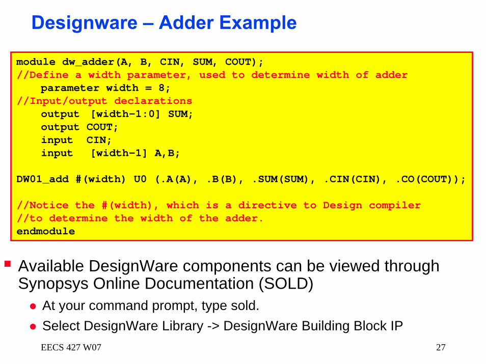