横向交变载荷下涂层紧固件的防松性能研究livrepository.liverpool.ac.uk/3019127/1/zhou...
TRANSCRIPT

Anti-loosening performance of coatings on fasteners
subjected to dynamic shear load
Junbo Zhou a, Jianhua Liu a, Huajiang Ouyang b, Zhenbing Cai a, Jinfang Peng a, Minhao Zhu a,*
a Tribology Research Institute, Southwest Jiaotong University, Chengdu 610031, China
b School of Engineering, University of Liverpool, Liverpool L69 3GH, UK
Abstract:
Self-loosening issues of fasteners under dynamic shear load have been
investigated in this paper. Three kinds of typical coatings, PTFE, MoS2, and TiN, are
applied to bolts and nuts tested in this investigation. This paper reveals the loosening
mechanisms of fasteners and assesses the anti-loosening performance of three
coatings by the tightening characteristics, loosening curves and the damage of thread
surface, as well as comparison with the anti-loosening performance of three coatings
under different load forms. The results indicate that PTFE coating and MoS2 coating
have a significant anti-loosening effect, whereas the anti-loosening performance of
TiN coating is not so satisfactory. And an appropriate increase of initial tightening
torque can significantly improve the anti-loosening effect. In addition, microscopic
analyses of PTFE coating and MoS2 coating demonstrate that a reduced initial
tightening torque leads to fretting wear on the thread contact surfaces of fasteners,
thereby aggravating the damage.
Key words: bolted fastener, loosening curve, fretting, coating, dynamic shear load
* Corresponding author: Tel.: +86 28 87600715; fax: +86 28 87600723.
E-mail address: [email protected] (M. Zhu).1
1 Introduction
Two kinds of the most common modes of threaded fasteners failure under
dynamic loads are fatigue and self-loosening. Self-loosening is often encountered
when threaded fasteners are subjected to transverse or shear load. Self-loosening can
cause gradual loss or even complete loss of the clamping force in bolted connections.
Ultimately, it is likely to lead to the occurrence of severe safety incidents. There has
been much research on this topic. Self-loosening mechanisms [1-16] and various
influencing factors [17-21] were studied through experiments, theoretical analysis and
numerical simulation. A variety of measures were proposed to prevent self-loosening,
such as chemical locking [21], Step Lock Bolt (SLB) [22], double-nut [8, 23] et al.
However, loosening of threaded fasteners is still common. Therefore, the study of
loosening mechanisms and improvement in anti-loosening performance are still an
important issue which is worthy of in-depth research.
Over recent years, the loosening process of threaded fasteners had been
extensively studied under different loading conditions. However, there has not been a
universal acceptance of the mechanisms of the self-loosening process. Early works
focused on loosening due to axial loading (dynamic loads acting along the fastener
axis) [1-6]. Goodier et al. pointed out that radial sliding motions between the threads
of the bolt and the nut or the interfaces of the clamped bearing surfaces were
important factors for loosening of a threaded coupling structure under axial vibration
[1]. Basava and Hess found that the clamping force could remain steady, decrease or
increase when the assembly was subjected to axial vibration, which was related to the
vibration frequency, amplitude and the frictional force between the contact surfaces
[2]. However, Sakai pointed out that the clamping force might be reduced under the
axial vibration [3]. Nassar and co-workers suggested that the loosening mechanism
was the irreversible plastic deformation of bolts under axial vibration [4, 5]. Liu found
2

that the loosening mechanism of bolted joints under axial excitation was the plastic
deformation of the structure and fretting wear between contact surfaces [6].
On the other hand, experimental studies in 1960s by Junker demonstrated that
loosening was more severe when a joint was subjected to shear loading [7]. A mass of
researchers have focused on the responses under the dynamic transverse load or
displacement. Sase found that the loosening of fasteners was mainly caused by two
factors under a transverse displacement [8, 22]. One was the relative slip between
threads of the bolt and the nut, the other was the relative slip between the bolt (or nut)
surface and the surface of the fastened material. The loosening analysis of bolted
joints subjected to dynamic shear load was done by Pai and Hess [9, 10]. They found
that fasteners loosening occurred as a result of complete or localized slip at the thread
and head contact surfaces. Fasteners can loosen under lower loads than that
previously expected because of localized slip at the contact surfaces, which was
confirmed by Dinger and Friedrich [11]. Shoji found that the relative slip between
threads was recurrent, which led to a rotation of the nut large enough to cause the bolt
to loosen [12]. Yang further noted that with the increasing number of load cycles, the
relative slip gradually accumulated which reduced the preload continuously and
eventually resulted in the failure of the connection of the fastening bolts [13]. Studies
conducted by Jiang and co-workers revealed that the self-loosening process of bolted
joints subjected to a transverse displacement could be divided into two distinguishable
stages [14-16]. In the first stage there was no relative rotation between nut and bolt,
and loosening was caused by material deformation. The second stage was
characterized by obvious backing-off of the nut and rapid decrease of the clamping
force.
Coating and lubrication are often used for reducing friction coefficients of
threaded fasteners [24, 25]. However, the effect of friction coefficients on the
loosening process is controversial. On one hand, increased friction coefficient means
an increased friction torque for resisting the relative rotation or slip at the thread and
3
head contact surfaces which plays a role on anti-loosening. Daadbin and Chow
described a theoretical model for a threaded connection under impact loading [26].
They found that the increase of the friction coefficient decreased the preload loss.
Houari [18] and Karamis [27] showed that the increase of the bearing friction reduced
the loosening rate. Zaki and Nassar [19] found increase of the coating thickness
decreased friction coefficients of the thread and the head bearing, therefore thick
coated fasteners would loosen at a faster rate than thin coated fasteners [28].
Sanclemente discovered that friction coefficients decreased with the application of
lubricant which promoted slippage and thereby loosening [20]. However, that paper
also pointed out that when lubrication was applied in combination with higher
preload, the resulting effect was beneficial for vibration resistance. On the other hand,
the torque–tension relationship for threaded fasteners is highly sensitive to friction
coefficient variation between the turning surfaces at the head/nut interface and threads
[29]. The decrease of friction coefficients increases the preload under the same initial
tightening torque which leads to a better anti-loosening performance. Liu pointed out
that adding a lubricant of MoS2 on bolted joints was a good method to prevent
loosening when bolted joint was subjected to axial excitation [6]. Hence, the effect of
coating on the self-loosening of threaded fasteners should be investigated.
Solid lubricating coatings are highly regarded in scientific and industrial
communities due to their excellent friction reduction and wear resistance properties
[30]. Coating used on fasteners can change friction coefficient and thus different
coatings have a different anti-loosening performance. However, there is very little
research on the anti-loosening performance of coatings. PTFE is one of the most
commonly used solid lubricants, which exhibits an ultra-low coefficient of friction
[31]. MoS2 is a popular solid lubricant used widely in machinery equipment to reduce
or eliminate various wear damage [32]. TiN coating is widely used to enhance the
surface properties under wear and corrosion conditions due to its attractive properties
such as high hardness, high adhesion strength [33, 34]. Research on the anti-loosening
4

performance of these typical coatings will provide theoretical support and engineering
guidance to prevent loosening for bolt-connected structures.
In this paper, two kinds of typical anti-friction coatings (PTFE and MoS 2) and
anti-wear coating (TiN) are applied to fasteners and investigate their anti-loosening
performance under dynamic shear load. The evolution curves of the clamping force of
bolts are obtained and the damages of the thread surfaces in contact are analysed. This
paper reveals the mechanism of loosening as fretting of surface coating and assesses
the anti-loosening performance of these typical coatings. In addition, this paper also
explores the differences of the anti-loosening performance of three coatings under
different load forms.
2 Experimental details
2.1 Test device and parameters
Self-loosening experiments of fasteners are carried out by the electro-hydraulic
servo fatigue testing machine with a custom designed testing fixture under cyclic
shear load. The schematic of the test machine is shown in Fig. 1. The upper fixture is
connected to the grip of the fatigue testing machine while the lower fixture is fixed to
the test stand. The upper and the lower fixtures are made of 1045 steel with the
thickness of 25mm. The upper fixture and the lower fixture are clamped by a bolt and
a nut. The load cell is placed between the upper fixture and the lower fixture. It is
connected to a data acquisition system in order to real-timely monitor the clamping
force. In order to protect the load cell from fretting wear, two thin washers made of
aluminium alloy are placed between the load cell and the bolt testing fixture.
5
Fig. 1 Schematic of the test machine
Load-controlled experiments are conducted. Dynamic shear load is the
controlling parameter which is applied by the fatigue testing machine and measured
by high-precision mechanical sensors.
According to the related standard, an appropriate level of preload corresponds to
60–70% of the nominal yield strength of the bolt [35]. Accordingly for M12mm
grade-8.8 bolts, the proper preload ranges from 18.2kN to 21.2kN. Therefore, the self-
loosening experiments in the study are conducted with a preload of 20kN, a median
value between 18.2kN and 21.2kN. However in practice, controlling-torque method is
adopted to control preload. An initial tightening torque (M0) is applied to achieve a
specified torque through slowly tightening the bolt using a digital torque wrench. In
order to assess the anti-loosening performance of different coatings more effectively,
two groups of experimental parameters are selected: (a) applying the same initial
tightening torque M0 =72Nm; (b) applying the same preload P0 =20kN.
Preliminary tests of uncoated fasteners for self-loosening experiment are
performed to determine the test parameters. In the preliminary tests, four different
dynamic shear load levels are applied in experiments, which respectively are ±4kN,
6
±6kN, ±7kN and ±8kN. It is found that when the shear load is ±4kN, the self-
loosening curve is similar to the loosening curve under the shear load of ±6kN. When
the shear load increases to ±7kN or ±8kN, the bolts become completely loosened in
less than 5000 cycles. The reason may be that when the shear load is large enough to
overcome the static friction between the two clamping plates, an excessive lateral
slippage between them occurs and the clamping force decreases quickly. So the
dynamic shear load is selected as ±6kN in experiments of coated fasteners. In
the preliminary tests, two loading regimes of 200000 and 1000000 cycles are used and
it is found that the self-loosening curve yields similar results. To save time, 200000
cycles of loading is used in experiments of coated fasteners.
The reason for choosing the frequency in the tests as 10Hz is as follows. First,
the frequency of 10Hz is the frequency commonly used in the field of mechanical
engineering. For example, fasteners on train bogies are subjected to an excitation of
frequency of about 10Hz. Secondly, for the electro-hydraulic servo fatigue testing
machine, the frequency of 10Hz is relatively easy to achieve. So all experiments are
conducted at a frequency of 10Hz in air at room temperature.
2.2 Preparation and characterization of coatings
Bolts and nuts used in this study are M12×1.75 mm of grade 8.8. In order to
reduce the dispersion of preload and loosening values, a number of high-quality bolts
and nuts are machined using 1045 steel. Relevant parameters and thread profile of the
testing bolts can be found in the reference [35]. The composition and main
characteristics of 1045 steel are listed in Tables 1 and 2, respectively.
Table 1 The chemical composition of 1045 steel (wt. %)
Material C Si Mn Ni Cr P S
1045 Steel 0.45 0.27 0.65 0.25 0.25 ≤0.04 ≤0.04
Table 2 The main characteristics of 1045 steel
7
MaterialYield strength
/MPa
Tensile strength
/MPa
Elastic modulus
/GPaPoisson's ratio
1045 Steel 650 850 210 0.3
Three kinds of typical coatings, PTFE, MoS2 and TiN, are applied to blots and
nuts to study the effect of coatings on loosening. As previously mentioned, Nassar and
Zaki [19] found that the increase of the coating thickness decreased the friction
coefficient between threads and the friction coefficient between the bolt (or nut) and
the bearing surface. Therefore, the coating thickness may affect the loosening
behaviour and it is necessary to choose the appropriate coating thickness before
coating preparation. On one hand, if the thickness of coating is too small, the coating
may be worn out quickly during the pre-loading process. On the other hand, if the
coating thickness is too large, the fit between the bolt and the nut would be affected,
resulting in difficulty in applying tightening torque. Thus, the thickness of the coating
is chosen to be a reasonable value of 15 micrometers for PTFE coating or MoS2
coating. As to TiN coating, since TiN coating is a typical anti-wear coating, the
thickness of TiN coating can be appropriately reduced. Thus, the thickness of TiN
coating is chosen as 5 micrometers.
The preparation of the three coatings is as follows: (1) PTFE coating is prepared
using spraying. The fine PTFE powders are uniformly dispersed in adhesive of epoxy.
After descaling, rusting and sand blasting, the mixture is sprayed onto the surfaces of
fasteners by a spray gun. Then the coating is solidified by heat curing at 200 °C for 1
hour. The thickness is 15±1m. (2) MoS2 coating is prepared in a similar way to
PTFE coating. The thickness is also 15±1m. (3) The PVD TiN coating, with
thickness of 5±1m, is deposited on the fasteners by an ion-plating equipment (MIP-
800) at a bias voltage of -100 V to -150 V and a mixed gas (N 2 + He) pressure of
0.6Pa. The characteristic parameters of coatings are listed in Tables 3.
Table 3 The characteristic parameters of coatings
8
Coatings Preparation Thickness Hardness
PTFE spraying 15±1m 23±2 HV
MoS2 spraying 15±1m 60±5 HV
TiN PVD 5±1m 2500±200 HV
Fig.2 The morphology of the fastener after coating treatment
(a) the cross sectional morphology of coating/substrate, (b) the thread surface of
coated fasteners
Fig. 2 shows the morphology of the fasteners after coating treatment. Fig. 2(a)
shows a cross sectional morphology of coating/substrate. It can be seen from Fig. 2(a)
9
that the thickness of coatings does not change significantly in the observation range.
Fig. 2(b) shows the thread surface morphology of the three kinds of coated fasteners.
It can be seen that there is no spalling in either coatings. Based on the above
observations, we believe that the three coatings are sufficiently uniform.
All test specimens, screws, washers and fixtures are cleaned with acetone to
remove surface contamination before self-loosening testing. As a comparison, some
uncoated fasteners are also tested.
Each self-loosening experiment is repeated five times for coated fasteners and
uncoated fasteners at identical test parameters. After self-loosening tests, the
morphologies of wear scar are examined by a scanning electron microscope (SEM)
and chemical compositions of damage zone are analysed by Energy Dispersive X-ray
(EDX).
3 Results and discussion
3.1 The anti-loosening performance of three coatings
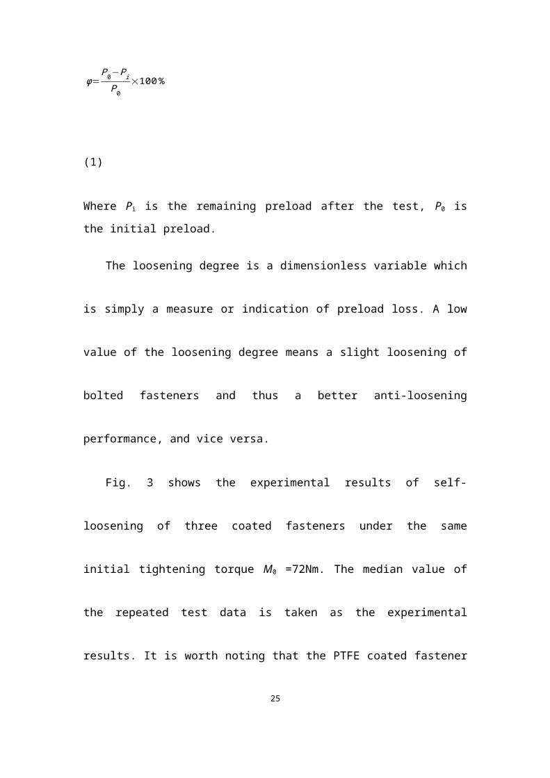
The loosening degree () is defined as the ratio of the loss of preload and the
initial preload [20].
ϕ=P0−Pi
P0×100 %
(1)
Where Pi is the remaining preload after the test, P0 is the initial preload.
The loosening degree is a dimensionless variable which is simply a measure or
indication of preload loss. A low value of the loosening degree means a slight
loosening of bolted fasteners and thus a better anti-loosening performance, and vice
versa.
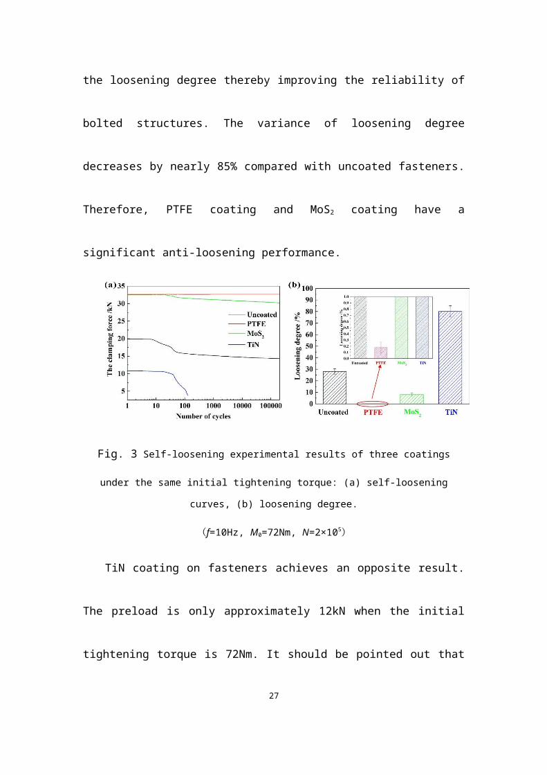
Fig. 3 shows the experimental results of self-loosening of three coated fasteners
10
under the same initial tightening torque M0 =72Nm. The median value of the repeated
test data is taken as the experimental results. It is worth noting that the PTFE coated
fastener begin slipping when the tightening torque is 60Nm. So the initial tightening
torque is selected as 60Nm for PTFE coated fastener.
It is observed form Fig. 3 that different coatings result in quite different anti-
loosening performances under the same initial tightening torque. As shown in Fig.
3(a), the clamping force of PTFE coated fasteners is virtually no change and the
loosening degree of PTFE coated fasteners is close to zero (Fig. 3(b)). The clamping
force of MoS2 coated fasteners does not obviously decline and the average degree of
loosening is only 8.08%, which decreases by 70% with uncoated fasteners as a
comparison. More importantly, adding PTFE and MoS2 coated fasteners can reduce
the scatter of test data of the loosening degree thereby improving the reliability of
bolted structures. The variance of loosening degree decreases by nearly 85%
compared with uncoated fasteners. Therefore, PTFE coating and MoS2 coating have a
significant anti-loosening performance.
Fig. 3 Self-loosening experimental results of three coatings under the same initial tightening
torque: (a) self-loosening curves, (b) loosening degree.
(f=10Hz, M0=72Nm, N=2×10⁵)TiN coating on fasteners achieves an opposite result. The preload is only
approximately 12kN when the initial tightening torque is 72Nm. It should be pointed
11

out that Fig. 3(b) shows the loosening degree of TiN coated fasteners is around 80%.
However, the actual situation is likely to be more serious than 80%. What happened in
the laboratory experiments was that, when the clamping force decreased to 4kN, the
dynamic shear load can no longer be applied and loosening tests were aborted due to
the excessive displacement between the upper fixture and lower fixture. It can be
concluded that TiN coating allows complete loosening under the initial tightening
torque (M0=72Nm). Therefore, a fastener with TiN coating has an insignificant effect
on anti-loosening performance under this initial tightening torque.
Under the same initial tightening torque, the anti-loosening performance between
different coatings is very obvious, which is attributed to the difference in tightening
characteristic of various coatings. It is assumed the threads friction coefficient t
equals to the friction coefficient between the bolt (or nut) and the bearing surface b
under various experimental parameters. The tightening characteristics of various
coatings can be theoretically calculated using Eq. (2) and Eq. (3) [36-37].
M 0=KP0d (2)
M 0=P0(P
2 π+
μ t rt
cos β+μbrb )
(3)
where M0 is the tightening torque applied to the bolt head/nut; P0 is the preload; K is
the nut factor; P is the thread pitch; is half of the thread flank angle; d2 is the basic
pitch diameter of thread; d0 is the hole diameter of the clamped body; t is the friction
coefficient between threads;b is the friction coefficient between the bolt (or nut) and
the bearing surface; rt is the effective contact radius between threads; rb is the
effective bearing radius of the bearing contact area under the turning head or nut. The
dimensions of the bolts used in this series of tests are given in Table 4.
Table 4. Bolt dimensional details.
12
Parameters value
Thread diameter, d 12 mm
Thread pitch, p 1.75mm
the thread flank angle, 60°
The outer bearing diameter, D0 18.0 mm
The hole diameter of the clamped body, d0 13.0 mm
The effective thread radius , rt 5.43mm
the effective bearing radius, rb 7.82mm
Fig. 4 shows the tightening characteristics of various coatings. It is observed
from Fig. 4 that coatings have a significant effect on the nut factor and friction
coefficients in threaded fasteners. PTFE coating and MoS2 coating can effectively
reduce the nut factor and friction coefficients which decreases by nearly 50%
compared with uncoated fasteners. So under the same initial tightening torque, as
shown in Fig. 5, the initial preload of fasteners with PTFE coating or MoS2 coating is
approximately doubled of those of uncoated fasteners. Higher preload leads to reduce
loosening or no loosening [8, 15, 20]. As to TiN coating, the initial preload is only
half of those of uncoated fasteners. Under a lower preload, the friction force decreases
and the shear force easily overcomes the friction force and the occurrence of slippage
increases, causing the rapid decrease of the clamping force even complete looseness
of fasteners (Fig. 3(a)).
13

Fig. 4 The tightening characteristics of various coatings. (a) nut factor k (b) friction
coefficients
Fig. 5 The preload of coated fasteners under the same initial tightening torque
Fig. 6 shows the self-loosening experimental results of three coated fasteners
under the same preload P0=20kN. It should be noted that the nut factor of TiN coating
is so high that fasteners are distorted before the preload reaches 20kN. In several
experiments, the preload can only be applied to approximately 19kN. So the initial
preload is selected 19kN for TiN coated fasteners.
Fig. 6(a) shows the clamping force reduction with the number of cycles. It is
experimentally observed from Fig. 6(a) that a typical self-loosening process due to
dynamic shear load can be divided into three distinct stages including a stable stage, a
rapid declining stage and a slow declining stage.
14

(1) The first stage: at the beginning of around 50th cycles, the clamping force is
nearly constant. The duration of this stage is not long, only about 5 seconds. This is
probably because it takes a few seconds for the testing machine to achieve 6kN (the
amplitude of the dynamic shear load). From the beginning of the experiment to
obtaining the amplitude of shear load takes a small amount of times which
corresponds to this stage.
(2) The second stage: from 50th cycles to about 2000th cycles, the clamping
force decreases significantly. This stage corresponds to the second stage of the self-
loosening process of bolted joints subjected to a transverse displacement researched
by Jiang and co-workers [14-16]. Liu [6] and Yu [38] found that the self-loosening
process of bolted joints under axial excitation also had this stage. Previous research
showed that the obvious backing-off of the nut [14, 15] and the removal of asperities
on contact surfaces in this stage led to reduction of the clamping force. In addition,
dynamic shear load generates slippage between the two clamped plates which reduced
the clamping force.
(3) The third stage: from 2000th cycles to 200,000 cycles, the clamping force
slowly decreases. This may be because of the occurrence of localized slip, so-called
partial slip in fretting, at the thread and head contact surfaces under dynamic shear
load [10, 11]. Fretting leads to a stable friction coefficient and wear, thereby the
clamping force declines slowly.
15

Fig. 6 The self-loosening experimental results of coated fasteners under the same preload: (a) self-
loosening curves, (b) loosening degree, (c) initial tightening torque.
(f=10Hz, P0=20kN, N=2×10⁵)Fig. 6(b) and Fig. 6(c) show the average and variance of the loosening degree
and the initial tightening torque. It can be noticed in Fig. 6(b) that different coatings
result in very different anti-loosening performance under the same preload. In terms
of loosening degree, PTFE has the best anti-loosening performance while TiN is the
worst. The average of loosening degree of PTFE and MoS2 coated fasteners is
respectively 14.17% and 19.20%, which decreases by nearly 40% compared with
uncoated fasteners. The average of loosening degree of TiN coated fasteners is only
22.16% which slightly decreases compared with uncoated fasteners. More
importantly, adding PTFE coating and MoS2 coating can reduce the scatter of test data
of the loosening degree. The variance of loosening degree of PTFE and MoS2 coated
fasteners decreases nearly 30% compared with uncoated fasteners. Considering the
difficulty of generating the same preload P0=20kN, as shown in Fig. 6(c), the preload
of the PTFE coated fasteners can be obtained at a low initial tightening torque level,
whereas the TiN coated fasteners cannot obtain the same preload at such a low level
of initial tightening torque.
Therefore, PTFE coating or MoS2 coating not only reduces the loosening degree
but also reduces the scatter of test data of the loosening degree thereby improving the
reliability of bolted structures. This may be because adding PTFE coating or MoS2
coating causes friction coefficients and asperity to decreases, thereby the contact area
increases and the plastic deformation decreases under the same dynamic shear load.
Thus the residual axial clamping force increases and the loosening degree decreases.
Past studies have shown that a steel surface coated with a PVD TiN coating has a
higher roughness [34]. So the contact areas of TiN coated fasteners are relatively
small, thereby the plastic deformation increases under the same dynamic shear load.
In addition, the nut factor of TiN coating is so high that it needs to be applied a
relatively high initial tightening torque to generating the required preload, resulting in
increasing plastic deformation of threaded surface. Thus the residual axial clamping
force reduces and the loosening degree increases.
16

In addition, through comparison between Fig. 3(b) and Fig. 6(b), the anti-
loosening performance is more significant under a higher initial tightening torque.
When the initial tightening torque is 60Nm, as shown in Fig. 3(b), the loosening
degree of PTFE coated fasteners is close to zero which indicates that the anti-
loosening performance of PTFE coating is extremely significant. When the initial
tightening torque reduces to 30Nm, as shown in Fig. 6(b), the loosening degree
increases to 14.17% which indicates that the anti-loosening performance decreases
under a lower initial tightening torque. When the initial tightening torque (M0) is
72Nm, the degree of loosening of MoS2 coated fasteners is only 8.08% (Fig. 3(b)).
When the initial tightening torque reduces to 35Nm, the degree of loosening is
19.20%, more than doubled of that under a higher tightening torque. TiN coated
fasteners exhibits complete loosening under the lower initial tightening torque
(M0=72Nm). When the initial tightening torque increases to 110Nm, the loosening
degree of TiN coated fasteners is 22.16%, which indicates that adding TiN coating on
fasteners has a certain anti-loosening performance under the higher initial tightening
torque.
3.2 SEM investigation
It is reported that the distribution of axial load along a fastener is so uneven that
the first three threads bear about 70% of the total axial load while the first thread
carries more than 30% [39, 40]. Past research indicated that the degree of thread
surface damage decreased with the increase of working thread ring [38, 41]. So the
damage of the first thread is analyzed using SEM and EDX.
Fig. 7 shows the SEM morphologies and EDX patterns corresponding to wear
scar of the first thread surface of uncoated fasteners. It can be seen from Fig. 7 that
regions near the top of the thread show serious furrow while other regions show
significant delamination. The EDX analyses of wear scars show that point B presents
a higher O-element peak than that of point A. Therefore, the main wear mechanism of
uncoated fasteners is abrasive wear, delamination and a slight oxidation wear which
are typical characteristics of fretting [42].
17
Fig. 7 Microscopic damage for uncoated fasteners: (a) SEM micrograph, (b) EDX
spectrum corresponding to point A and point B.
Fig. 8 shows the SEM morphologies and EDX patterns corresponding to wear
scars of the first thread surface of the PTFE coated fasteners under different initial
tightening torques.
18
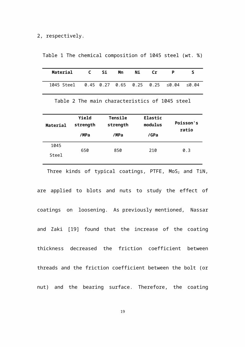
Fig. 8 Microscopic damage for PTFE coated fasteners under (a) initial tightening
torque M0=60Nm, (b) initial tightening torque M0=30Nm.
It can be seen from Fig. 8 that with the decrease of initial tightening torque, the
damage of PTFE coated fasteners exacerbates. Under a higher initial tightening
torque, as shown in Fig. 8(a), the damage of PTFE coated fasteners is slight abrasion
and exfoliation in the edge regions. When the initial tightening torque reduces to
30Nm, as shown in Fig. 8(b), the wear is more serious. Nearly half of the coating may
be removed. Seriously damaged areas occur on the thread edge and it is found that
19
these regions show serious furrow and significant delamination. The EDX analyses of
wear scars show that a small amount of O-element is present at point A and point B.
This may be because slight oxidation reaction occurs at the threaded surface before
the application of coating. It also may be due to oxidation wear during experiments.
Therefore, the main wear mechanism of PTFE coated fasteners is fatigue wear,
abrasive wear and slight oxidation wear which are in accordance with the typical
characteristics of fretting that means fretting wear occurs on the bolt contact surfaces.
Fretting exacerbates damage and leads to a higher loosening degree which indicates
that loosening of bolts is closely related to fretting.
Fig. 9 shows the SEM morphologies and EDX patterns corresponding to wear
scar of the first thread surface of the MoS2 coated fasteners under different initial
tightening torques. Similar to PTFE coated fasteners, with the decrease of initial
tightening torque, the damage of MoS2 coated fasteners also exacerbates. Under a
higher initial tightening torque, as shown in Fig. 9(a), the damage of MoS2 coated
fasteners is slight abrasion and a small amount of areas exhibit exfoliation, mainly in
the edge position. When the initial tightening torque reduces to 35Nm, as shown in
Fig. 9(b), the damage of MoS2 coated fasteners is discontinuous. In area I, the
material components of point A are analyzed. It is found that the region contains only
iron and carbon which suggests that coating of the bolt has been completely removed.
The damaged surface in this area shows obvious plastic furrow and delamination
phenomenon. In other regions, denoted as area II, the coating displays relatively
minor abrasion. The EDX analyses of wear scars show that point B presents Mo-
element and S-element which indicates that MoS2 coating has a good self-lubricating
effect. Meanwhile, a small amount of O-element is present at point B. This may be
due to oxidation wear during experiments. Therefore, the main wear mechanism of
MoS2 coated fasteners is fatigue wear, abrasive wear, oxidation wear and
delamination which are in accordance with the typical characteristics of fretting.
Fretting exacerbates damage and leads to a higher loosening degree which indicates
20

that loosening of bolts is closely related to fretting.
Fig. 9 Microscopic damage for MoS2 coated fasteners under (a) initial tightening
torque M0=72Nm, (b) initial tightening torque M0=35Nm.
(f=10Hz, N=2×10⁵)As to TiN coatings, some TiN coated bolts are distorted during the test. The
reason of distortion of TiN coated bolts is that the nut factor of TiN coated fasteners is
21

so high that in order to achieve the same preload, the required tightening torque is
larger than for uncoated fasteners. It can be seen from Fig. 6 that the preload of TiN
coated fasteners can only be applied to approximately 19kN and the initial tightening
torque is approximately 110Nm. Such a high tightening torque may result in a greater
frictional stress between the thread contact surfaces. In fact, the bolts undergo serious
plastic deformation under this loading condition or even fracture. After loosening
testing, some TiN coated fasteners are difficult to unscrew because of distortion or
fracture (Fig. 10).
Fig. 10 TiN coated fasteners after loosening tests: (a) fracture (b) distortion.
Therefore, adding TiN coating on fasteners gains a certain anti-loosening
performance under the same preload (Fig. 6), however it is not an ideal method to
prevent loosening.
3.3 Effects of loading form
Many studies show that loosening was more severe when a joint is subjected to
transverse alternating loading than axial alternating loading [7, 17]. However, anti-
loosening performance of coating fasteners under the two alternating loading has not
been reported in the open literature. The authors’ research team systematically studied
the dynamic behaviour of coated fasteners under axial excitation using experimental
and numerical methods [43]. The aim of this work is to explore the differences of the
22
anti-loosening performances of three coated fasteners under dynamic shear load and
axial load. Fig. 11 shows the loosening degrees of three coated fasteners under two
different loading forms.
Fig. 11 The loosening degree under different loading forms
It is obvious in Fig. 11 that different load forms result in different anti-loosening
performance of coatings. On one hand, when coated fasteners are subjected to shear
load, three kinds of coatings demonstrate obvious anti-loosening performances. PTFE
coating has the best anti-loosening performance while TiN coating ranks the worst.
On the other hand, when coated fasteners are subjected to axial loading, the anti-
loosening performance of MoS2 coating is somewhat encouraging, while TiN coating
still ranks the worst with loosening degree being even higher than those of uncoated
fasteners. PTFE coating possesses relatively small anti-loosening ability compared
with uncoated fasteners.
In addition, it can also be concluded from Fig. 11 that the loosening degree is
more severe when the fasteners are subjected to shear load than axial load, especially
for uncoated fasteners and MoS2 coated fasteners. The possible reason is that the shear
load is acting in the same direction as the relative slip and thus is more likely to cause
relative slip, which may be more likely to lead to fretting damage.
In actual situation, fasteners are likely to withstand both axial and shear loads. To
investigate the effect of the direction of the externally applied load, Zhang and Jiang
23

[17] designed an experimental fixture which could change the angle between the
directions of the applied force in relation to the contact surface of the two clamped
plates. An angle of 0 deg represents the pure shear or transverse loading while an
angle of 90 deg represents axial loading. An angle of 30 deg applies both axial and
shear loads. The results suggest that an axial load component greatly enhances
resistance of the bolted joints to self-loosening. However, their work shows that
fatigue dominates failure under axial load component. So fatigue strength may
become a great concern when there is a large axial load component.
In summary, compared to fasteners are subjected to shear load, when fasteners
withstand both axial and shear loads at the same time, the risk of loosening may be
reduced, but risk of fatigue is possible. Such a phenomenon is worth a further
investigation in future.
4 Conclusions
According to the results obtained by a series of experiments on fasteners with
three different kinds of coatings under different initial tightening torques and dynamic
load forms, the following conclusions can be drawn.
(1) PTFE coating and MoS2 coating have a significant anti-loosening capability
and this capability is stronger under higher initial tightening torques. The anti-
loosening performance of TiN coating is not very satisfactory.
(2) The loosening curve can be generally divided into three stages: a stable stage,
a rapidly declining stage and a slowly declining stage.
(3) The loosening mechanism of coated fasteners is related to fretting under
dynamic shear load. Fretting aggravates wear which can readily cause loosening.
(4) The anti-loosening performance of coatings exist obvious differences under
shear load and axial load respectively. And the loosening degree is more severe when
the fasteners are subjected to shear load than axial load, especially for uncoated
24
fasteners and MoS2 coated fasteners.
Acknowledgments
The authors gratefully acknowledge the financial support provided by China
National Funds for Distinguished Young Scientists (No.51025519), the Changjiang
Scholarships and Innovation Team Development Plan (No.IRT1178), and the Self-
Topic Fund of Traction Power State Key Laboratory (No. 2016TPL-Z03).
Nomenclature
M0 Tightening torque applied to the bolt head/nut
P0 Preload
K Nut factor
P Thread pitch
Half of the thread flank angle
d2 Basic pitch diameter of thread
d0 Hole diameter of the clamped body
t Friction coefficient between threads
b Friction coefficient between the bolt (or nut) and the bearing surface
rt Effective contact radius between threads
rb Effective bearing radius of the bearing contact area under the turning
head or nut.
References
25

[1] Goodier J N, Sweeney R J. Loosening by vibration of threaded fastenings.
Mechanical Engineering, 67: 794–800 (1945)
[2] Basava S, Hess D P. Bolted joint clamping force variation due to axial vibration.
Sound and Vibration, 210 (2):255-265 (1998)
[3] Sakai T. Mechanism for a bolt and nut self-loosening under repeated bolt axial
tensile load. Solid Mechanics and Materials Engineering, 5(11):627-639 (2011)
[4] Nassar S A, Yang X X, Gandham S V T, Wu Z J. Nonlinear deformation behavior
of clamped bolted joints under a separating service load. Journal of Pressure Vessel
Technology, 133(2):021001 (2011)
[5] Yang X X, Nassar S A, Wu Z J, Meng A D. Nonlinear behavior of preloaded
bolted joints under a cyclic separating load. Journal of Pressure Vessel Technology,
134(1): 011206 (2012)
[6] Liu J H, Ouyang H J, Peng J F, Zhang C B, Zhou P Y , Ma L J, Zhu M H.
Experimental and numerical studies of bolted joints subjected to axial excitation.
Wear, 346–347: 66-77 (2016)
[7] Junker G H. New criteria for self-loosening fasteners under vibration. SAE,
Transactions, 78: 314-335 (1969)
[8] Sase N, Nishioka K, Koga S, Fujii H. An anti-loosening screw-fastener innovation
and its evaluation. Materials Processing Technology, 77:209–215 (1998)
[9] Pai N G, Hess D P. Three-dimensional finite element analysis of threaded fastener
loosening due to dynamic shear load. Engineering Failure Analysis, 9:383–402 (2009)
[10] Pai N G, Hess D P. Experimental study of loosening of threaded fastener due to
dynamic shear loads. Sound and vibration 253(3) 585-602 (2002)
[11] Dinger G, Friedrich C. Avoiding self-loosening failure of bolted joints with
numerical assessment of local contact state. Engineering Failure Analysis, 18(8):
26
2188-2200 (2011)
[12] Shoji Y, Sawa T. Analytical research on mechanism of bolt loosening due to
lateral loads. ASME Pressure Vessels and Piping Division Conference. Denver,
Colorado, USA (2005)
[13] Yang G X, Xie J L, Xie Y Y. Study on mechanism of anti-loosening of a new type
of nut based on fem. Engineering mechanics,12:224-243 (in Chinese) (2010)
[14] Jiang Y, Zhang M, Chu-Hwa Lee. A study of early stage self-loosening of bolted
joints. Mechanical Design, 125(3): 518-526 (2003)
[15] Jiang, Y, Zhang M, Tae-Won Park, Chu-Hwa Lee. An experimental study of self-
loosening of bolted joints. Mechanical Design, 126(5): 925-931 (2004)
[16] Zhang M, Jiang Y, Chu-Hwa Lee. Finite element modeling of self-loosening of
bolted joints. Mechanical Design, 129(2): 218-266 (2007)
[17] Zhang M, Jiang Y, Lee C H. An experimental investigation of the effects of
clamped length and loading direction on self-loosening of bolted joints.Journal of
Pressure Vessel Technology, 128(3):129-136,(2004)
[18] Housari B A, Nassar S A. Effect of thread and bearing friction coefficients on the
vibration-induced loosening of threaded fasteners. Journal of Vibration and Acoustics,
129(4): 484-494 (2007)
[19] Zaki A M, Nassar S A, Xianjie Y. Effect of thread and bearing friction
coefficients on the self-loosening of preloaded countersunk-head bolts under periodic
transverse excitation. Journal of Tribology, 132(3): 031601-1 (2010)
[20] Sanclemente J A, Hess D P. Parametric study of threaded fastener loosening due
to cyclic transverse loads. Engineering Failure Analysis 14: 239–249 (2007)
[21] Anirban Bhattacharya, Avijit Sen, Santanu Das. An investigation on the anti-
loosening characteristics of threaded fasteners under vibratory conditions.
27
Mechanism and Machine Theory 45:1215–1225 (2010)
[22] Sase N, Fujii H. Optimizing study of SLBs for higher anti-loosening
performance. Materials Processing Technology, 119:174–179 (2001)
[23] Izumi S, Yokoyama T, Kimurab M, Sakaia S. Loosening-resistance evaluation of
double-nut tightening method and spring washer by three-dimensional finite element
analysis. Engineering Failure Analysis, 16(5): 1510–1519 (2009)
[24] Zou Q, Sun T S, Nassar S A, Barber G C, Gumul A K. Effect of lubrication on
friction and torque-tension relationship in threaded fasteners. STLE/ASME
International Joint Tribology Conference October 22-25, San Antonio, TX, USA
(2006)
[25] Housari, B A, Nassar, S A. Effect of thread and bearing friction coefficients on
the vibration-induced loosening of threaded fasteners. Vibration and Acoustics,
129:484-494 (2007)
[26] Daadbin A, Chow Y M. A theoretical model to study thread loosening.
Mechanics and Machine Theory, 27: 69-74 (1992)
[27] Karamiş M B, Selçuk B. Analysis of the friction behavior of bolted joints. Wear
166(1): 73-83 (1993)
[28] Nassar S A, Zaki A M. Effect of coating thickness on the friction coefficients and
torque-tension relationship in threaded fasteners. Journal of Tribology, 31:021301-1
(2009)
[29] Bickford J H. Introduction to the design and behavior of bolted joints [M] 4th ed.
The Chemical Rubber Company Press, Florida, (2007)
[30] Fan X Q, Xue Q J, Wang L P. Carbon-based solid–liquid lubricating coatings for
space applications–A review. Friction, 3(3): 191–207 (2015)
28
[31] Yuan X D, Yang X J. A study on friction and wear properties of PTFE coatings
under vacuum conditions. Wear, 269:291–297 (2010)
[32] Luo J, Zhu M H, Wang Y D, Zheng J F, Mo J L. Study on rotational fretting wear
of bonded MoS2 solid lubricant coating prepared on medium carbon steel. Tribology
International, 44: 1565-1570 (2011)
[33] Shan L, Wang Y X, Li J L, Li H. Wu X D, Chen J M. Tribological behaviours of
PVD TiN and TiCN coatings in artificial seawater. Surface & Coatings Technology,
226:40-50 (2013)
[34] Paskvale S, Remškar M, Čekada M. Tribological performance of TiN, TiAlN and
CrN hard coatings lubricated by MoS2 nanotubes in Polyalphaolefin oil. Wear, 352-
353:72–78 (2016)
[35] Cheng D X. Handbook of Mechanical Design [M]. Beijing: Chemical Industry
Press, (in Chinese) (2016)
[36] Nassar S A, El-Khiamy H, Barber, G C, Zuo D J, Sun T S. An experimental study
of bearing and thread friction in fasteners. Journal of Tribology, 127(2): 263-272
(2005)
[37] Nassar S A, Barber G C, Zuo D J. Bearing friction torque in bolted joints.
Tribology Transactions, 48:69–75 (2005)
[38] Yu Z T, Liu J H, Zhang C Q, Zhou J B, Peng J F, Ma L J, et al. An experimental
study on self-Loosening of bolted joints under axial vibration. Tribology, 35(6):732-
736 (in Chinese) (2015)
[39] Yamamoto A. Theory and Calculation of thread connection [M]. Translated by
Guo K Q, Gao S J, Wang X F et al. shanghai: shanghai scientific and technological
literature press (in Chinese) (1982)
[40] Zhao H. Analysis of the load distribution in a bolt-nut connector. Computers and
Structures, 53(6):1465-1472 (1994)
29

[41] Liu J H, Ouyang H J, Ma L J, Zhang C Q, Zhu M H. Numerical and theoretical
studies of bolted joints under harmonic shear displacement. Latin American Journal of
Solids and Structures, 12(1):115-132 (2015)
[42] Zhou Z R, Zhu M H. Dual-fretting wear [M]. Shanghai: Shanghai Jiaotong
University Press, (in Chinese) (2004)
[43] Liu J H. Research on the self-loosening mechanism of bolted joints under axial
excitation. Ph.D Thesis. Sichuan (China): Southwest Jiaotong University (2016)
30