eecc550 - shaaban #1 midterm review summer2000 7-10-2000 the von-neumann computer model partitioning...
Post on 19-Dec-2015
218 views
TRANSCRIPT

EECC550 - ShaabanEECC550 - Shaaban#1 Midterm Review Summer2000 7-10-2000
The Von-Neumann Computer ModelThe Von-Neumann Computer Model• Partitioning of the computing engine into components:
– Central Processing Unit (CPU): Control Unit (instruction decode, sequencing of operations), Datapath (registers, arithmetic and logic unit, buses).
– Memory: Instruction and operand storage.
– Input/Output (I/O).
– The stored program concept: Instructions from an instruction set are fetched from a common memory and executed one at a time.
-Memory
(instructions, data)
Control
DatapathregistersALU, buses
CPUComputer System
Input
Output
I/O Devices

EECC550 - ShaabanEECC550 - Shaaban#2 Midterm Review Summer2000 7-10-2000
CPU OrganizationCPU Organization• Datapath Design:
– Capabilities & performance characteristics of principal Functional Units (FUs):
– (e.g., Registers, ALU, Shifters, Logic Units, ...)– Ways in which these components are interconnected (buses
connections, multiplexors, etc.).– How information flows between components.
• Control Unit Design:– Logic and means by which such information flow is controlled.– Control and coordination of FUs operation to realize the targeted
Instruction Set Architecture to be implemented (can either be implemented using a finite state machine or a microprogram).
• Hardware description with a suitable language, possibly using Register Transfer Notation (RTN).

EECC550 - ShaabanEECC550 - Shaaban#3 Midterm Review Summer2000 7-10-2000
Hierarchy of Computer ArchitectureHierarchy of Computer Architecture
I/O systemInstr. Set Proc.
Compiler
OperatingSystem
Application
Digital DesignCircuit Design
Instruction Set Architecture
Firmware
Datapath & Control
Layout
Software
Hardware
Software/Hardware Boundary
High-Level Language Programs
Assembly LanguagePrograms
Microprogram
Register TransferNotation (RTN)
Logic Diagrams
Circuit Diagrams
Machine Language Program
EECC550 - ShaabanEECC550 - Shaaban#4 Midterm Review Summer2000 7-10-2000
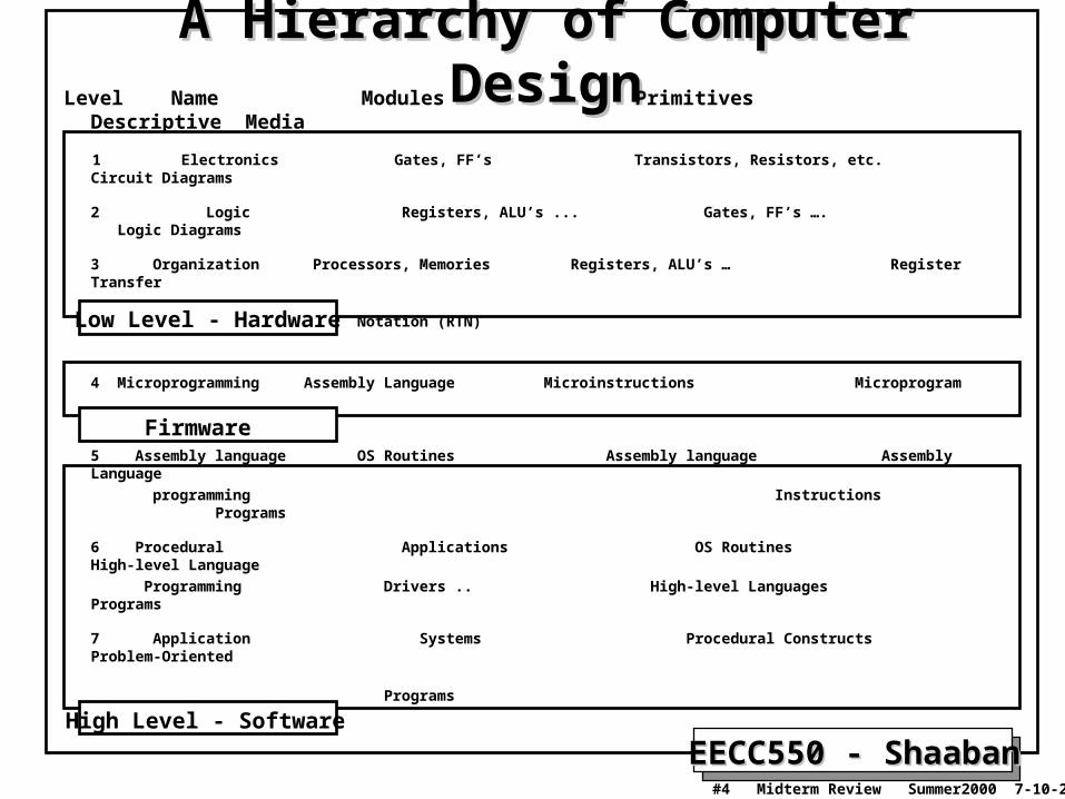
A Hierarchy of Computer DesignA Hierarchy of Computer DesignLevel Name Modules Primitives Descriptive Media
1 Electronics Gates, FF’s Transistors, Resistors, etc. Circuit Diagrams
2 Logic Registers, ALU’s ... Gates, FF’s …. Logic Diagrams
3 Organization Processors, Memories Registers, ALU’s … Register Transfer
Notation (RTN)
4 Microprogramming Assembly Language Microinstructions Microprogram
5 Assembly language OS Routines Assembly language Assembly Language
programming Instructions Programs
6 Procedural Applications OS Routines High-level Language
Programming Drivers .. High-level Languages Programs
7 Application Systems Procedural Constructs Problem-Oriented
Programs
Low Level - Hardware
Firmware
High Level - Software

EECC550 - ShaabanEECC550 - Shaaban#5 Midterm Review Summer2000 7-10-2000
Instruction Set Architecture (ISA)Instruction Set Architecture (ISA)“... the attributes of a [computing] system as seen by the programmer, i.e. the conceptual structure and functional behavior, as distinct from the organization of the data flows and controls the logic design, and the physical implementation.” – Amdahl, Blaaw, and Brooks, 1964.
The instruction set architecture is concerned with:
• Organization of programmable storage (memory & registers): Includes the amount of addressable memory and number of available registers.
• Data Types & Data Structures: Encodings & representations.
• Instruction Set: What operations are specified.
• Instruction formats and encoding.
• Modes of addressing and accessing data items and instructions
• Exceptional conditions.
EECC550 - ShaabanEECC550 - Shaaban#6 Midterm Review Summer2000 7-10-2000
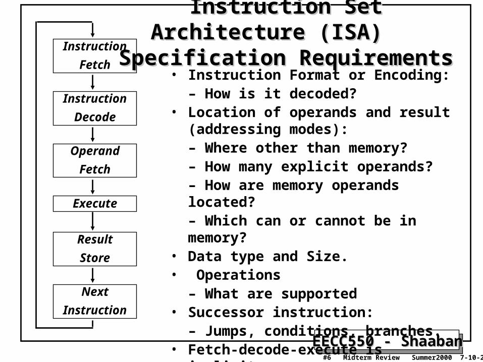
Instruction Set Architecture (ISA) Instruction Set Architecture (ISA) Specification RequirementsSpecification RequirementsInstruction
Fetch
Instruction
Decode
Operand
Fetch
Execute
Result
Store
Next
Instruction
• Instruction Format or Encoding:– How is it decoded?
• Location of operands and result (addressing modes):– Where other than memory?– How many explicit operands? – How are memory operands located?– Which can or cannot be in memory?
• Data type and Size.• Operations
– What are supported• Successor instruction:
– Jumps, conditions, branches.• Fetch-decode-execute is implicit.

EECC550 - ShaabanEECC550 - Shaaban#7 Midterm Review Summer2000 7-10-2000
Types of Instruction Set ArchitecturesTypes of Instruction Set ArchitecturesAccording To Operand Addressing FieldsAccording To Operand Addressing Fields
Memory-To-Memory Machines:– Operands obtained from memory and results stored back in memory by any instruction
that requires operands.– No local CPU registers are used in the CPU datapath.– Include:
• The 4 Address Machine.• The 3-address Machine.• The 2-address Machine.
The 1-address (Accumulator) Machine: – A single local CPU special-purpose register (accumulator) is used as the source of one
operand and as the result destination.
The 0-address or Stack Machine:– A push-down stack is used in the CPU.
General Purpose Register (GPR) Machines:– The CPU datapath contains several local general-purpose registers which can be used as
operand sources and as result destinations.– A large number of possible addressing modes.– Load-Store or Register-To-Register Machines: GPR machines where only data
movement instructions (loads, stores) can obtain operands from memory and store results to memory.

EECC550 - ShaabanEECC550 - Shaaban#8 Midterm Review Summer2000 7-10-2000
Types of Instruction Set ArchitecturesTypes of Instruction Set Architectures Memory-To-Memory Machines: Memory-To-Memory Machines:
The 4-Address MachineThe 4-Address Machine• No program counter (PC) or other CPU registers are used.• Instructions specify:
– Location of first operand. - Location of second operand.– Place to store the result. - Location of next instruction.
Memory
Op1
Op2
Res
Nexti
::
Op1Addr:
Op2Addr:
ResAddr:
NextiAddr:
+
CPUInstruction:
add Res, Op1, Op2, Nexti
Meaning:
(Res Op1 + Op2)
NextiAddrResAddr Op1Addr Op2AddraddBits: 8 24 24 24 24
Instruction Format
Opcode Whichoperation
Where toput result
Where to findnext instruction
Where to find operands

EECC550 - ShaabanEECC550 - Shaaban#9 Midterm Review Summer2000 7-10-2000
• A program counter is included within the CPU which points to the next instruction.• No CPU storage (general-purpose registers).
Types of Instruction Set ArchitecturesTypes of Instruction Set Architectures Memory-To-Memory Machines: Memory-To-Memory Machines:
The 3-Address MachineThe 3-Address Machine
Instruction:
add Res, Op1, Op2
Meaning:
(Res Op1 + Op2)
ResAddr Op1Addr Op2AddraddBits: 8 24 24 24
Instruction Format
Opcode Whichoperation
Where toput result
Where to find operands
Memory
Op1
Op2
Res
Nexti
::
Op1Addr:
Op2Addr:
ResAddr:
NextiAddr:
+
CPU
ProgramCounter (PC)
Where to findnext instruction
24

EECC550 - ShaabanEECC550 - Shaaban#10 Midterm Review Summer2000 7-10-2000
• The 2-address Machine: Result is stored in the memory address of one of the operands.
Types of Instruction Set ArchitecturesTypes of Instruction Set Architectures Memory-To-Memory Machines: Memory-To-Memory Machines:
The 2-Address MachineThe 2-Address Machine
Instruction:
add Op2, Op1
Meaning:
(Op2 Op1 + Op2)
Where toput result
Op2Addr Op1AddraddBits: 8 24 24
Instruction Format
Opcode Whichoperation
Where to find operands
Memory
Op1
Op2,Res
Nexti
::
Op1Addr:
Op2Addr:
NextiAddr:
+
CPU
ProgramCounter (PC)
Where to findnext instruction
24

EECC550 - ShaabanEECC550 - Shaaban#11 Midterm Review Summer2000 7-10-2000
• A single accumulator in the CPU is used as the source of one operand and result destination.
Instruction:
add Op1
Meaning:
(Acc Acc + Op1)
Types of Instruction Set ArchitecturesTypes of Instruction Set Architectures The 1-address (Accumulator) MachineThe 1-address (Accumulator) Machine
Op1AddraddBits: 8 24
Instruction Format
Opcode Whichoperation
Where to find operand1
Memory
Op1
Nexti
::
Op1Addr:
NextiAddr:
+
CPU
ProgramCounter (PC)
Where to findnext instruction
24
Accumulator
Where to findoperand2, andwhere to put result

EECC550 - ShaabanEECC550 - Shaaban#12 Midterm Review Summer2000 7-10-2000
• A push-down stack is used in the CPU.
Types of Instruction Set ArchitecturesTypes of Instruction Set Architectures The 0-address (Stack) MachineThe 0-address (Stack) Machine
Instruction: push Op1Meaning: (TOS Op1)
Instruction: addMeaning: (TOS TOS + SOS)
Instruction Format
addBits: 8
Opcode
Instruction: pop ResMeaning: (Res TOS)
Op1AddrpushBits: 8 24
Instruction Format
Opcode Where to find operand
ResAddr popBits: 8 24
Instruction Format
Opcode Memory Destination
CPU
ProgramCounter (PC)
24
Memory
Op1
Nexti
::
Op1Addr:
NextiAddr:
TOS
SOS
etc.
Stackpush
Op2Op2Addr:
ResResAddr:
+
add
Op1
Op2, Respop
8

EECC550 - ShaabanEECC550 - Shaaban#13 Midterm Review Summer2000 7-10-2000
• CPU contains several general-purpose registers which can be used as operand sources and result destination.
Types of Instruction Set ArchitecturesTypes of Instruction Set Architectures General Purpose Register (GPR) MachinesGeneral Purpose Register (GPR) Machines
Instruction: load R8, Op1Meaning: (R8 Op1)
+
CPU
ProgramCounter (PC)
24
Memory
Op1
Nexti
::
Op1Addr:
NextiAddr:
R8
R7
R6
R5
R4
R3
R2
R1
Registersload
add
store
Op1AddrloadBits: 8 3 24
Instruction Format
Opcode Where to find operand1
R8
Instruction: add R2, R4, R6Meaning: (R2 R4 + R6)
addBits: 8 3 3 3
Instruction Format
Opcode Des Operands
R2 R4 R6
Instruction: store R2, Op2Meaning: (Op2 R2)
ResAddrstoreBits: 8 3 24
Instruction Format
Opcode Destination
R2

EECC550 - ShaabanEECC550 - Shaaban#14 Midterm Review Summer2000 7-10-2000
Expression Evaluation Example with 3-, 2-, Expression Evaluation Example with 3-, 2-, 1-, 0-Address, And GPR Machines1-, 0-Address, And GPR Machines
For the expression A = (B + C) * D - E where A-E are in memory
0-Address Stack
push B push C add push D mul push E sub pop A
8 instructionsCode size:23 bytes5 memoryaccesses
3-Address
add A, B, Cmul A, A, Dsub A, A, E
3 instructionsCode size:30 bytes9 memory accesses
2-Address
load A, Badd A, Cmul A, Dsub A, E
4 instructionsCode size:28 bytes12 memoryaccesses
1-AddressAccumulator
load B add C mul D sub E store A
5 instructionsCode size:20 bytes5 memory accesses
GPRRegister-Memory
load R1, B add R1, C mul R1, D sub R1, E store A, R1
5 instructions Code size: about 22 bytes 5 memory accesses
Load-Store
load R1, Bload R2, Cadd R3, R1, R2load R1, Dmul R3, R3, R1load R1, Esub R3, R3, R1store A, R3
8 instructions Code size: about 29 bytes 5 memory accesses

EECC550 - ShaabanEECC550 - Shaaban#15 Midterm Review Summer2000 7-10-2000
Typical ISA Addressing ModesTypical ISA Addressing Modes
Register
Immediate
Displacement
Indirect
Indexed
Absolute
Memory indirect
Autoincrement
Autodecrement
Scaled
R4 R4 + R3
R4 R4 + 3
R4 R4 + Mem[10+ R1]
R4 R4 + Mem[R1]
R3 R3 +Mem[R1 + R2]
R1 R1 + Mem[1001]
R1 R1 + Mem[Mem[R3]]
R1 R1 + Mem[R2]
R2 R2 + d
R2 R2 - d
R1 R1 + Mem[R2]
R1 R1+ Mem[100+ R2 + R3*d]
Add R4, R3
Add R4, #3
Add R4, 10 (R1)
Add R4, (R1)
Add R3, (R1 + R2)
Add R1, (1001)
Add R1, @ (R3)
Add R1, (R2) +
Add R1, - (R2)
Add R1, 100 (R2) [R3]
Addressing Sample Mode Instruction Meaning

EECC550 - ShaabanEECC550 - Shaaban#16 Midterm Review Summer2000 7-10-2000
Three Examples of Instruction Set EncodingThree Examples of Instruction Set Encoding
Variable Length Encoding: VAX (1-53 bytes)
Operations &no of operands
Addressspecifier 1
Addressfield 1
Address specifier n
Address field n
Operation Addressfield 1
Addressfield 2
Addressfield3
Fixed Length Encoding: DLX, MIPS, PowerPC, SPARC
Operation Address Specifier
Addressfield
Operation AddressSpecifier 1
AddressSpecifier 2
Address field
OperationAddress Specifier Address
field 1
Address field 2
Hybrid Encoding: IBM 360/370, Intel 80x86

EECC550 - ShaabanEECC550 - Shaaban#17 Midterm Review Summer2000 7-10-2000
Instruction Set Architecture Trade-offsInstruction Set Architecture Trade-offs• 3-address machine: shortest code sequence; a large number of bits
per instruction; large number of memory accesses.
• 0-address (stack) machine: Longest code sequence; shortest individual instructions; more complex to program.
• General purpose register machine (GPR): – Addressing modified by specifying among a small set of registers
with using a short register address (all machines since 1975).
– Advantages of GPR:• Low number of memory accesses. Faster, since register access is
currently still much faster than memory access. • Registers are easier for compilers to use.• Shorter, simpler instructions.
• Load-Store Machines: GPR machines where memory addresses are only included in data movement instructions between memory and registers (all machines after 1980).

EECC550 - ShaabanEECC550 - Shaaban#18 Midterm Review Summer2000 7-10-2000
Complex Instruction Set Computer (CISC)Complex Instruction Set Computer (CISC)• Emphasizes doing more with each instruction.
• Motivated by the high cost of memory and hard disk capacity when original CISC architectures were proposed:– When M6800 was introduced: 16K RAM = $500, 40M hard disk = $ 55, 000
– When MC68000 was introduced: 64K RAM = $200, 10M HD = $5,000
• Original CISC architectures evolved with faster, more complex CPU designs, but backward instruction set compatibility had to be maintained.
• Wide variety of addressing modes:• 14 in MC68000, 25 in MC68020
• A number instruction modes for the location and number of operands:
• The VAX has 0- through 3-address instructions.
• Variable-length or hybrid instruction encoding is used.
EECC550 - ShaabanEECC550 - Shaaban#19 Midterm Review Summer2000 7-10-2000
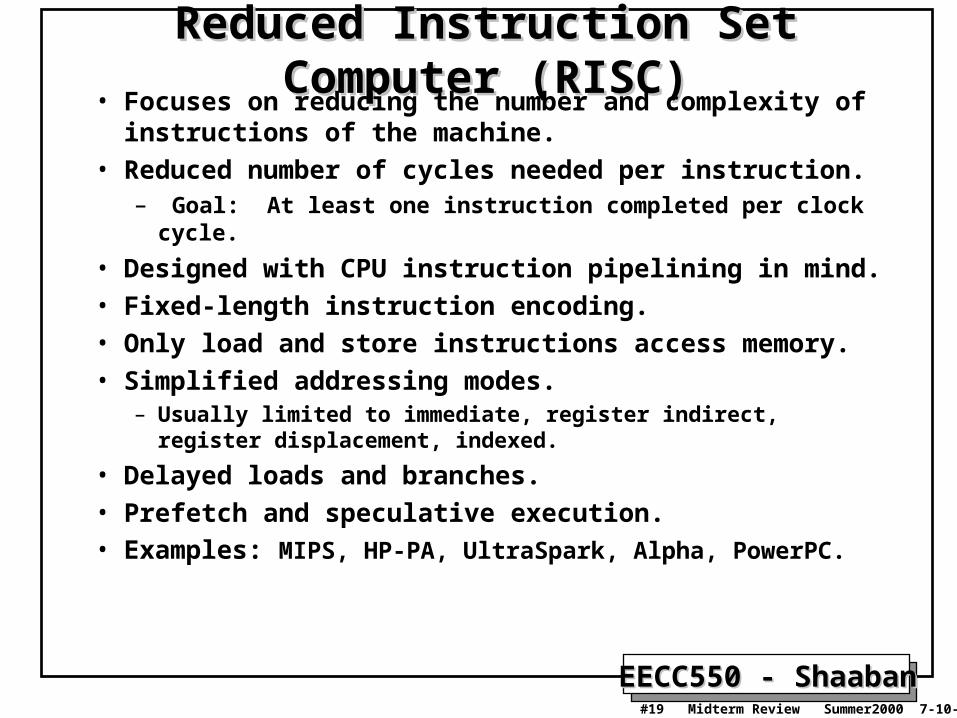
Reduced Instruction Set Computer (RISC)Reduced Instruction Set Computer (RISC)• Focuses on reducing the number and complexity of
instructions of the machine.
• Reduced number of cycles needed per instruction. – Goal: At least one instruction completed per clock cycle.
• Designed with CPU instruction pipelining in mind.
• Fixed-length instruction encoding.
• Only load and store instructions access memory.
• Simplified addressing modes.– Usually limited to immediate, register indirect, register
displacement, indexed.
• Delayed loads and branches.
• Prefetch and speculative execution.• Examples: MIPS, HP-PA, UltraSpark, Alpha, PowerPC.

EECC550 - ShaabanEECC550 - Shaaban#20 Midterm Review Summer2000 7-10-2000
RISC ISA Example: RISC ISA Example:
MIPS R3000MIPS R3000Instruction Categories:
• Load/Store.• Computational.• Jump and Branch.• Floating Point (using coprocessor).• Memory Management.• Special.
OP
OP
OP
rs rt rd sa funct
rs rt immediate
jump target
Instruction Encoding: 3 Instruction Formats, all 32 bits wide.
R0 - R31
PCHI
LO
Registers 4 Addressing Modes:• Base register + immediate offset
(loads and stores). • Register direct (arithmetic).• Immedate (jumps). • PC relative (branches).
Operand Sizes:• Memory accesses in any
multiple between 1 and 4 bytes.
R-Type
I-Type: ALULoad/Store, Branch
J-Type: Jumps

EECC550 - ShaabanEECC550 - Shaaban#21 Midterm Review Summer2000 7-10-2000
MIPS Memory Addressing & AlignmentMIPS Memory Addressing & Alignment• MIPS uses Big Endian operand storage in memory where the most
significant byte is in low memory (this is similar to IBM 360/370, Motorola 68k, Sparc, HP PA).
• MIPS requires that all words (32- bits) to start at memory addresses that are multiple of 4
• In general objects must fall on memory addresses that are multiple of their size.
msb
0 1 2 3
lsb
0 1 2 3
Aligned
NotAligned

EECC550 - ShaabanEECC550 - Shaaban#22 Midterm Review Summer2000 7-10-2000
MIPS Register Usage/Naming ConventionsMIPS Register Usage/Naming Conventions• In addition to the usual naming of registers by $ followed with register number,
registers are also named according to MIPS register usage convention as follows:
Register Number Name Usage Preserved on call? 0
12-3
4-78-15
16-2324-2526-27
28293031
$zero$at$v0-$v1
$a0-$a3$t0-$t7$s0-$s7$t8-$t9$k0-$k1$gp$sp$fp$ra
Constant value 0Reserved for assemblerValues for result and expression evaluationArgumentsTemporariesSavedMore temporariesReserved for operating systemGlobal pointerStack pointerFrame pointerReturn address
n.a.nono
yesnoyesnoyesyesyesyesyes

EECC550 - ShaabanEECC550 - Shaaban#23 Midterm Review Summer2000 7-10-2000
MIPS Addressing Modes/Instruction FormatsMIPS Addressing Modes/Instruction Formats
immedop rs rtImmediate
• All instructions 32 bits wide
immedop rs rt
register
Displacement:Base+index
+
Memory
immedop rs rt
PC
PC-relative
+
Memory
op rs rt rd
register
Register (direct)
First Operand Second Operand Destination

EECC550 - ShaabanEECC550 - Shaaban#24 Midterm Review Summer2000 7-10-2000
MIPS Arithmetic Instructions ExamplesMIPS Arithmetic Instructions ExamplesInstruction Example Meaning Comments
add add $1,$2,$3 $1 = $2 + $3 3 operands; exception possible
subtract sub $1,$2,$3 $1 = $2 – $3 3 operands; exception possible
add immediate addi $1,$2,100 $1 = $2 + 100 + constant; exception possible
add unsigned addu $1,$2,$3 $1 = $2 + $3 3 operands; no exceptions
subtract unsigned subu $1,$2,$3 $1 = $2 – $3 3 operands; no exceptions
add imm. unsign. addiu $1,$2,100 $1 = $2 + 100 + constant; no exceptions
multiply mult $2,$3 Hi, Lo = $2 x $3 64-bit signed product
multiply unsigned multu$2,$3 Hi, Lo = $2 x $3 64-bit unsigned product
divide div $2,$3 Lo = $2 ÷ $3, Lo = quotient, Hi = remainder
Hi = $2 mod $3
divide unsigned divu $2,$3 Lo = $2 ÷ $3, Unsigned quotient & remainder
Hi = $2 mod $3
Move from Hi mfhi $1 $1 = Hi Used to get copy of Hi
Move from Lo mflo $1 $1 = Lo Used to get copy of Lo

EECC550 - ShaabanEECC550 - Shaaban#25 Midterm Review Summer2000 7-10-2000
MIPS Arithmetic Instructions ExamplesMIPS Arithmetic Instructions ExamplesInstruction Example Meaning Comments
add add $1,$2,$3 $1 = $2 + $3 3 operands; exception possible
subtract sub $1,$2,$3 $1 = $2 – $3 3 operands; exception possible
add immediate addi $1,$2,100 $1 = $2 + 100 + constant; exception possible
add unsigned addu $1,$2,$3 $1 = $2 + $3 3 operands; no exceptions
subtract unsigned subu $1,$2,$3 $1 = $2 – $3 3 operands; no exceptions
add imm. unsign. addiu $1,$2,100 $1 = $2 + 100 + constant; no exceptions
multiply mult $2,$3 Hi, Lo = $2 x $3 64-bit signed product
multiply unsigned multu$2,$3 Hi, Lo = $2 x $3 64-bit unsigned product
divide div $2,$3 Lo = $2 ÷ $3, Lo = quotient, Hi = remainder
Hi = $2 mod $3
divide unsigned divu $2,$3 Lo = $2 ÷ $3, Unsigned quotient & remainder
Hi = $2 mod $3
Move from Hi mfhi $1 $1 = Hi Used to get copy of Hi
Move from Lo mflo $1 $1 = Lo Used to get copy of Lo

EECC550 - ShaabanEECC550 - Shaaban#26 Midterm Review Summer2000 7-10-2000
Instruction Comment
sw 500($4), $3 Store word
sh 502($2), $3 Store half
sb 41($3), $2 Store byte
lw $1, 30($2) Load word
lh $1, 40($3) Load halfword
lhu $1, 40($3) Load halfword unsigned
lb $1, 40($3) Load byte
lbu $1, 40($3) Load byte unsigned
lui $1, 40 Load Upper Immediate (16 bits shifted left by 16)
MIPS data transfer instructions MIPS data transfer instructions ExamplesExamples
0000 … 0000
LUI R5
R5

EECC550 - ShaabanEECC550 - Shaaban#27 Midterm Review Summer2000 7-10-2000
MIPS Branch, Compare, Jump Instructions Examples Instruction Example Meaning
branch on equal beq $1,$2,100 if ($1 == $2) go to PC+4+100 Equal test; PC relative branch
branch on not eq. bne $1,$2,100 if ($1!= $2) go to PC+4+100 Not equal test; PC relative branch
set on less than slt $1,$2,$3 if ($2 < $3) $1=1; else $1=0 Compare less than; 2’s comp. set less than imm. slti $1,$2,100 if ($2 < 100) $1=1; else $1=0
Compare < constant; 2’s comp.set less than uns. sltu $1,$2,$3 if ($2 < $3) $1=1; else $1=0 Compare less than; natural numbers
set l. t. imm. uns. sltiu $1,$2,100 if ($2 < 100) $1=1; else $1=0 Compare < constant; natural numbers
jump j 10000 go to 10000 Jump to target address
jump register jr $31 go to $31 For switch, procedure return
jump and link jal 10000 $31 = PC + 4; go to 10000 For procedure call

EECC550 - ShaabanEECC550 - Shaaban#28 Midterm Review Summer2000 7-10-2000
Example: C Assignment With Variable Index To MIPSExample: C Assignment With Variable Index To MIPS • For the C statement with a variable array index:
g = h + A[i];• Assume: g: $s1, h: $s2, i: $s4, base address of A[ ]: $s3
• Steps:– Turn index i to a byte offset by multiplying by four or by addition as
done here: i + i = 2i, 2i + 2i = 4i– Next add 4i to base address of A– Load A[i] into a temporary register.– Finally add to h and put sum in g
• MIPS Instructions:add $t1,$s4,$s4 # $t1 = 2*iadd $t1,$t1,$t1 # $t1 = 4*iadd $t1,$t1,$s3 #$t1 = address of A[i]
lw $t0,0($t1) # $t0 = A[i]add $s1,$s2,$t0 # g = h + A[i]

EECC550 - ShaabanEECC550 - Shaaban#29 Midterm Review Summer2000 7-10-2000
• While loop in C:while (save[i]==k) i = i + j;
• Assume MIPS register mapping:
i: $s3, j: $s4, k: $s5, base of save[ ]: $s6
• MIPS Instructions:Loop: add $t1,$s3,$s3 # $t1 = 2*i
add $t1,$t1,$t1 # $t1 = 4*i add $t1,$t1,$s6 # $t1 = Address
lw $t1,0($t1) # $t1 = save[i] bne $t1,$s5,Exit # goto Exit # if save[i]!=k
add $s3,$s3,$s4 # i = i + j j Loop # goto Loop
Exit:
Example: While C Loop to MIPSExample: While C Loop to MIPS
EECC550 - ShaabanEECC550 - Shaaban#30 Midterm Review Summer2000 7-10-2000
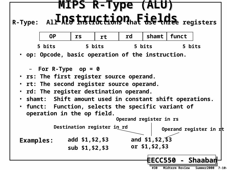
MIPS R-Type (ALU) Instruction FieldsMIPS R-Type (ALU) Instruction Fields
• op: Opcode, basic operation of the instruction. – For R-Type op = 0
• rs: The first register source operand.• rt: The second register source operand.• rd: The register destination operand.• shamt: Shift amount used in constant shift operations.• funct: Function, selects the specific variant of operation in the op
field.
OP rs rt rd shamt funct
6 bits 5 bits 5 bits 5 bits 5 bits 6 bits
R-Type: All ALU instructions that use three registers
add $1,$2,$3
sub $1,$2,$3
and $1,$2,$3or $1,$2,$3
Examples:
Destination register in rd Operand register in rt
Operand register in rs

EECC550 - ShaabanEECC550 - Shaaban#31 Midterm Review Summer2000 7-10-2000
MIPS ALU I-Type Instruction FieldsMIPS ALU I-Type Instruction FieldsI-Type ALU instructions that use two registers and an immediate value Loads/stores, conditional branches.
• op: Opcode, operation of the instruction.
• rs: The register source operand.
• rt: The result destination register.
• immediate: Constant second operand for ALU instruction.
OP rs rt immediate
6 bits 5 bits 5 bits 16 bits
add immediate: addi $1,$2,100
and immediate andi $1,$2,10
Examples:
Result register in rtSource operand register in rs
Constant operand in immediate

EECC550 - ShaabanEECC550 - Shaaban#32 Midterm Review Summer2000 7-10-2000
MIPS Load/Store I-Type Instruction FieldsMIPS Load/Store I-Type Instruction Fields
• op: Opcode, operation of the instruction.– For load op = 35, for store op = 43.
• rs: The register containing memory base address. • rt: For loads, the destination register. For stores, the source
register of value to be stored. • address: 16-bit memory address offset in bytes added to base
register.
OP rs rt address
6 bits 5 bits 5 bits 16 bits
Store word: sw 500($4), $3
Load word: lw $1, 30($2)
Examples:
Offset base register in rs
source register in rt
Destination register in rt Offsetbase register in rs

EECC550 - ShaabanEECC550 - Shaaban#33 Midterm Review Summer2000 7-10-2000
MIPS Branch I-Type Instruction FieldsMIPS Branch I-Type Instruction Fields
• op: Opcode, operation of the instruction.
• rs: The first register being compared
• rt: The second register being compared.
• address: 16-bit memory address branch target offset in words added to PC to form branch address.
OP rs rt address
6 bits 5 bits 5 bits 16 bits
Branch on equal beq $1,$2,100
Branch on not equal bne $1,$2,100
Examples:
Register in rsRegister in rt offset in bytes equal to
instruction field address x 4
EECC550 - ShaabanEECC550 - Shaaban#34 Midterm Review Summer2000 7-10-2000
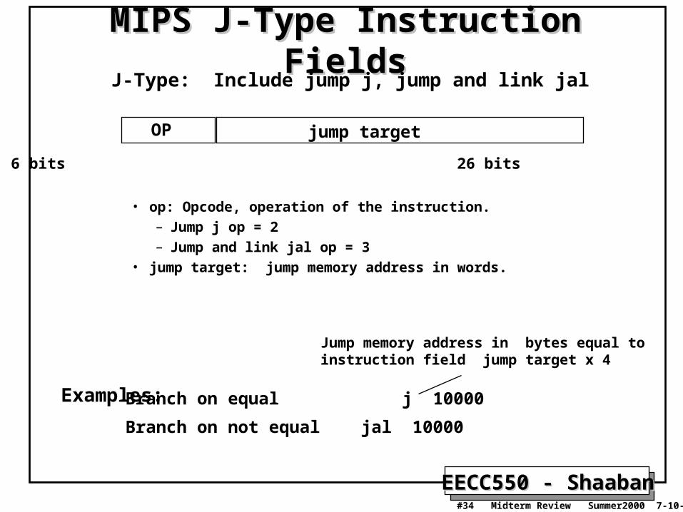
MIPS J-Type Instruction FieldsMIPS J-Type Instruction Fields
• op: Opcode, operation of the instruction.– Jump j op = 2– Jump and link jal op = 3
• jump target: jump memory address in words.
J-Type: Include jump j, jump and link jal
OP jump target
6 bits 26 bits
Branch on equal j 10000
Branch on not equal jal 10000
Examples:
Jump memory address in bytes equal toinstruction field jump target x 4

EECC550 - ShaabanEECC550 - Shaaban#35 Midterm Review Summer2000 7-10-2000
Computer Performance Evaluation:Computer Performance Evaluation:Cycles Per Instruction (CPI)Cycles Per Instruction (CPI)
• Most computers run synchronously utilizing a CPU clock running at a constant clock rate:
where: Clock rate = 1 / clock cycle
• A computer machine instruction is comprised of a number of elementary or micro operations which vary in number and complexity depending on the instruction and the exact CPU organization and implementation.– A micro operation is an elementary hardware operation that can be
performed during one clock cycle.
– This corresponds to one micro-instruction in microprogrammed CPUs.
– Examples: register operations: shift, load, clear, increment, ALU operations: add , subtract, etc.
• Thus a single machine instruction may take one or more cycles to complete termed as the Cycles Per Instruction (CPI).
EECC550 - ShaabanEECC550 - Shaaban#36 Midterm Review Summer2000 7-10-2000
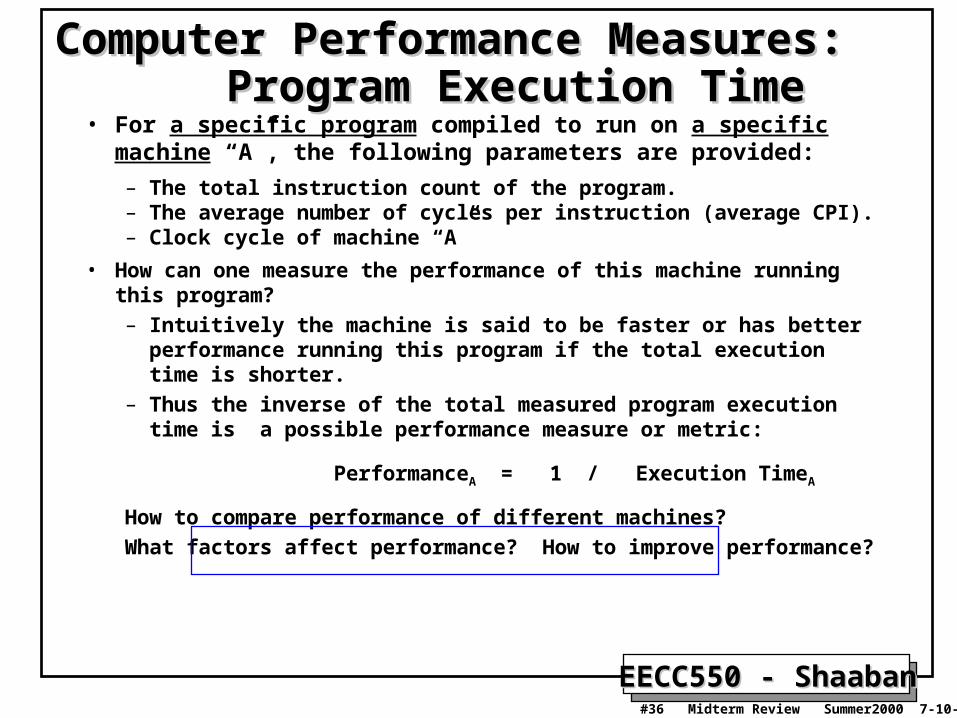
• For a specific program compiled to run on a specific machine “A”, the following parameters are provided:
– The total instruction count of the program.– The average number of cycles per instruction (average CPI).– Clock cycle of machine “A”
• How can one measure the performance of this machine running this program?– Intuitively the machine is said to be faster or has better performance
running this program if the total execution time is shorter. – Thus the inverse of the total measured program execution time is a
possible performance measure or metric:
PerformanceA = 1 / Execution TimeA
How to compare performance of different machines?
What factors affect performance? How to improve performance?
Computer Performance Measures: Computer Performance Measures: Program Execution TimeProgram Execution Time
EECC550 - ShaabanEECC550 - Shaaban#37 Midterm Review Summer2000 7-10-2000
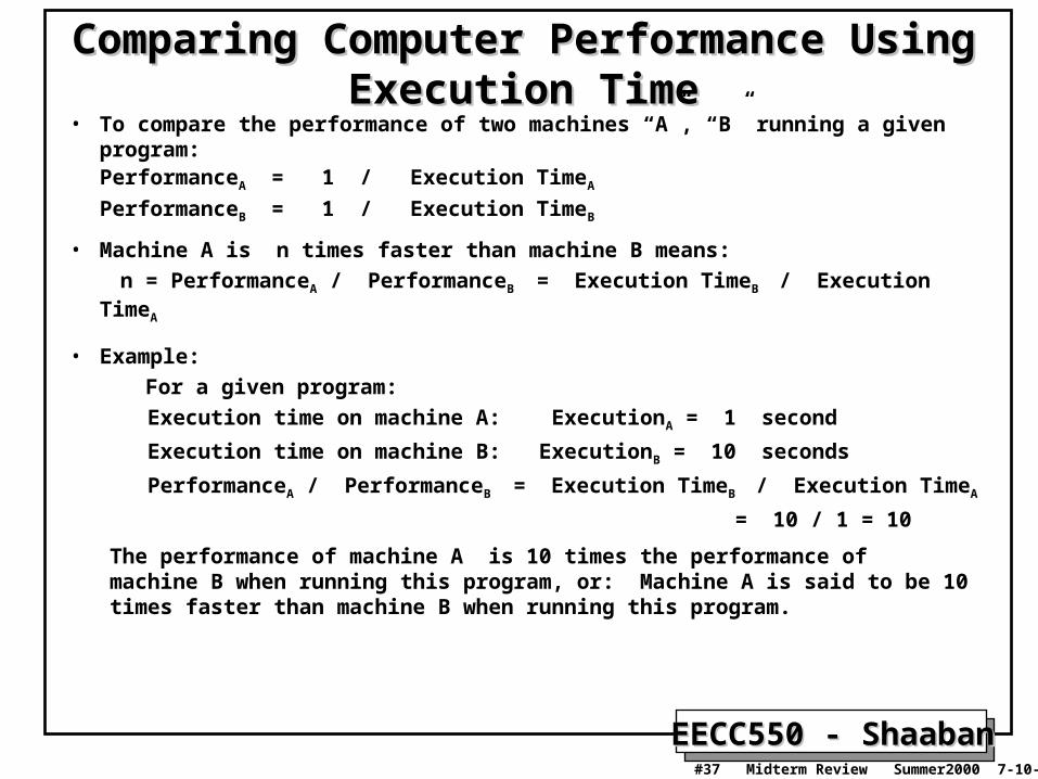
Comparing Computer Performance Using Comparing Computer Performance Using Execution TimeExecution Time
• To compare the performance of two machines “A”, “B” running a given program:PerformanceA = 1 / Execution TimeA
PerformanceB = 1 / Execution TimeB
• Machine A is n times faster than machine B means:
n = PerformanceA / PerformanceB = Execution TimeB / Execution TimeA
• Example:
For a given program:
Execution time on machine A: ExecutionA = 1 second
Execution time on machine B: ExecutionB = 10 seconds
PerformanceA / PerformanceB = Execution TimeB / Execution TimeA
= 10 / 1 = 10
The performance of machine A is 10 times the performance of machine B when running this program, or: Machine A is said to be 10 times faster than machine B when running this program.

EECC550 - ShaabanEECC550 - Shaaban#38 Midterm Review Summer2000 7-10-2000
CPU Execution Time: The CPU EquationCPU Execution Time: The CPU Equation• A program is comprised of a number of instructions
– Measured in: instructions/program
• The average instruction takes a number of cycles per instruction (CPI) to be completed. – Measured in: cycles/instruction
• CPU has a fixed clock cycle time = 1/clock rate – Measured in: seconds/cycle
• CPU execution time is the product of the above three parameters as follows:
CPU time = Seconds = Instructions x Cycles x Seconds
Program Program Instruction Cycle
CPU time = Seconds = Instructions x Cycles x Seconds
Program Program Instruction Cycle

EECC550 - ShaabanEECC550 - Shaaban#39 Midterm Review Summer2000 7-10-2000
CPU Execution Time: ExampleCPU Execution Time: Example• A Program is running on a specific machine with the
following parameters:– Total instruction count: 10,000,000 instructions
– Average CPI for the program: 2.5 cycles/instruction.
– CPU clock rate: 200 MHz.
• What is the execution time for this program:
CPU time = Instruction count x CPI x Clock cycle
= 10,000,000 x 2.5 x 1 / clock rate
= 10,000,000 x 2.5 x 5x10-9
= .125 seconds
CPU time = Seconds = Instructions x Cycles x Seconds
Program Program Instruction Cycle
CPU time = Seconds = Instructions x Cycles x Seconds
Program Program Instruction Cycle

EECC550 - ShaabanEECC550 - Shaaban#40 Midterm Review Summer2000 7-10-2000
Factors Affecting CPU PerformanceFactors Affecting CPU PerformanceCPU time = Seconds = Instructions x Cycles x
Seconds
Program Program Instruction Cycle
CPU time = Seconds = Instructions x Cycles x Seconds
Program Program Instruction Cycle
CPI Clock RateInstruction Count
Program
Compiler
Organization
Technology
Instruction SetArchitecture (ISA)
X
X
X
X
X
X
X X
X

EECC550 - ShaabanEECC550 - Shaaban#41 Midterm Review Summer2000 7-10-2000
Aspects of CPU Execution TimeAspects of CPU Execution TimeCPU Time = Instruction count x CPI x Clock cycle
Instruction CountInstruction Count
ClockClockCycleCycle
CPICPIDepends on:
CPU OrganizationTechnology
Depends on:
Program Used
CompilerISACPU Organization
Depends on:
Program UsedCompilerISA

EECC550 - ShaabanEECC550 - Shaaban#42 Midterm Review Summer2000 7-10-2000
Performance Comparison: ExamplePerformance Comparison: Example• From the previous example: A Program is running on a specific
machine with the following parameters:– Total instruction count: 10,000,000 instructions– Average CPI for the program: 2.5 cycles/instruction.– CPU clock rate: 200 MHz.
• Using the same program with these changes: – A new compiler used: New instruction count 9,500,000
New CPI: 3.0– Faster CPU implementation: New clock rate = 300 MHZ
• What is the speedup with the changes?
Speedup = (10,000,000 x 2.5 x 5x10-9) / (9,500,000 x 3 x 3.33x10-9 ) = .125 / .095 = 1.32
or 32 % faster after changes.
Speedup = Old Execution Time = Iold x CPIold x Clock cycleold
New Execution Time Inew x CPInew x Clock Cyclenew
Speedup = Old Execution Time = Iold x CPIold x Clock cycleold
New Execution Time Inew x CPInew x Clock Cyclenew

EECC550 - ShaabanEECC550 - Shaaban#43 Midterm Review Summer2000 7-10-2000
Instruction Types & CPIInstruction Types & CPI
• Given a program with n types or classes of instructions with the following characteristics:
Ci = Count of instructions of typei
CPIi = Average cycles per instruction of typei
Then:Then:
CPU clock cyclesi i
i
n
CPI C
1
EECC550 - ShaabanEECC550 - Shaaban#44 Midterm Review Summer2000 7-10-2000
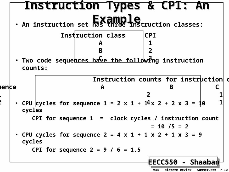
Instruction Types & CPI: An ExampleInstruction Types & CPI: An Example• An instruction set has three instruction classes:
• Two code sequences have the following instruction counts:
• CPU cycles for sequence 1 = 2 x 1 + 1 x 2 + 2 x 3 = 10 cycles
CPI for sequence 1 = clock cycles / instruction count
= 10 /5 = 2
• CPU cycles for sequence 2 = 4 x 1 + 1 x 2 + 1 x 3 = 9 cycles
CPI for sequence 2 = 9 / 6 = 1.5
Instruction class CPI A 1 B 2 C 3
Instruction counts for instruction classCode Sequence A B C 1 2 1 2 2 4 1 1
EECC550 - ShaabanEECC550 - Shaaban#45 Midterm Review Summer2000 7-10-2000
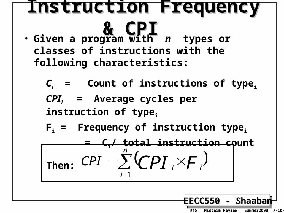
Instruction Frequency & CPIInstruction Frequency & CPI • Given a program with n types or classes of
instructions with the following characteristics:
Ci = Count of instructions of typei
CPIi = Average cycles per instruction of typei
Fi = Frequency of instruction typei
= Ci/ total instruction count
Then:
n
iii FCPICPI
1

EECC550 - ShaabanEECC550 - Shaaban#46 Midterm Review Summer2000 7-10-2000
Instruction Type Frequency & CPI: Instruction Type Frequency & CPI: A RISC ExampleA RISC Example
Typical Mix
Base Machine (Reg / Reg)
Op Freq Cycles CPI(i) % Time
ALU 50% 1 .5 23%
Load 20% 5 1.0 45%
Store 10% 3 .3 14%
Branch 20% 2 .4 18%
CPI = .5 x 1 + .2 x 5 + .1 x 3 + .2 x 2 = 2.2
n
iii FCPICPI
1
EECC550 - ShaabanEECC550 - Shaaban#47 Midterm Review Summer2000 7-10-2000
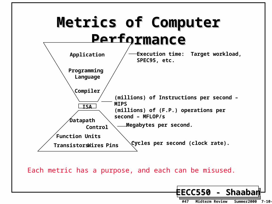
Metrics of Computer Metrics of Computer PerformancePerformance
Compiler
Programming Language
Application
DatapathControl
Transistors Wires Pins
ISA
Function UnitsCycles per second (clock rate).
Megabytes per second.
Execution time: Target workload,SPEC95, etc.
Each metric has a purpose, and each can be misused.
(millions) of Instructions per second – MIPS(millions) of (F.P.) operations per second – MFLOP/s

EECC550 - ShaabanEECC550 - Shaaban#48 Midterm Review Summer2000 7-10-2000
Actual Target Workload
Full Application Benchmarks
Small “Kernel” Benchmarks
Microbenchmarks
Pros Cons
• Representative• Very specific.• Non-portable.• Complex: Difficult to run, or measure.
• Portable.• Widely used.• Measurements useful in reality.
• Easy to run, early in the design cycle.
• Identify peak performance and potential bottlenecks.
• Less representative than actual workload.
• Easy to “fool” by designing hardware to run them well.
• Peak performance results may be a long way from real application performance
Types of BenchmarksTypes of Benchmarks
EECC550 - ShaabanEECC550 - Shaaban#49 Midterm Review Summer2000 7-10-2000
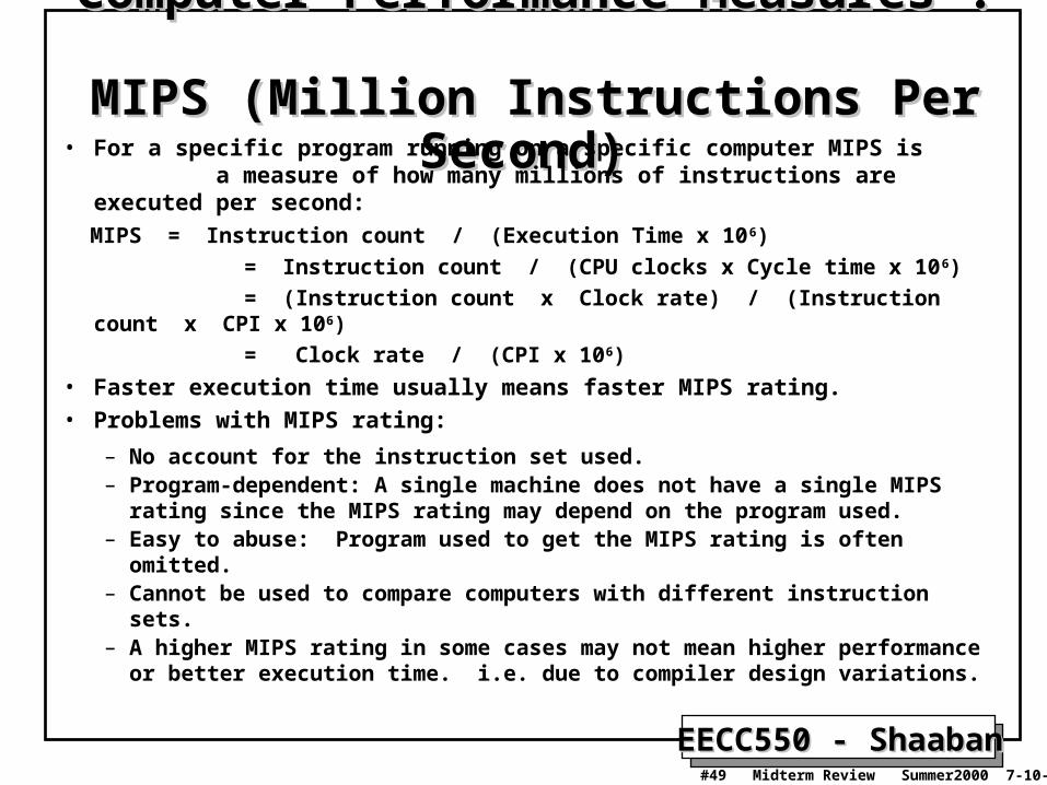
Computer Performance Measures : Computer Performance Measures : MIPS MIPS (Million Instructions Per Second)(Million Instructions Per Second)
• For a specific program running on a specific computer MIPS is a measure of how many millions of instructions are executed per second:
MIPS = Instruction count / (Execution Time x 106)
= Instruction count / (CPU clocks x Cycle time x 106)
= (Instruction count x Clock rate) / (Instruction count x CPI x 106)
= Clock rate / (CPI x 106)
• Faster execution time usually means faster MIPS rating.• Problems with MIPS rating:
– No account for the instruction set used.– Program-dependent: A single machine does not have a single MIPS rating
since the MIPS rating may depend on the program used.– Easy to abuse: Program used to get the MIPS rating is often omitted.– Cannot be used to compare computers with different instruction sets.– A higher MIPS rating in some cases may not mean higher performance or
better execution time. i.e. due to compiler design variations.

EECC550 - ShaabanEECC550 - Shaaban#50 Midterm Review Summer2000 7-10-2000
Computer Performance Measures : Computer Performance Measures : MFOLPS MFOLPS (Million FLOating-Point Operations Per Second)(Million FLOating-Point Operations Per Second)
• A floating-point operation is an addition, subtraction, multiplication, or division operation applied to numbers represented by a single or a double precision floating-point representation.
• MFLOPS, for a specific program running on a specific computer, is a measure of millions of floating point-operation (megaflops) per second:
MFLOPS = Number of floating-point operations / (Execution time x 106 )
• MFLOPS is a better comparison measure between different machines than MIPS.
• Program-dependent: Different programs have different percentages of floating-point operations present. i.e compilers have no floating- point operations and yield a MFLOPS rating of zero.
• Dependent on the type of floating-point operations present in the program.

EECC550 - ShaabanEECC550 - Shaaban#51 Midterm Review Summer2000 7-10-2000
Performance Enhancement Calculations:Performance Enhancement Calculations: Amdahl's Law Amdahl's Law
• The performance enhancement possible due to a given design improvement is limited by the amount that the improved feature is used
• Amdahl’s Law:
Performance improvement or speedup due to enhancement E: Execution Time without E Performance with E Speedup(E) = -------------------------------------- = --------------------------------- Execution Time with E Performance without E
– Suppose that enhancement E accelerates a fraction F of the execution time by a factor S and the remainder of the time is unaffected then:
Execution Time with E = ((1-F) + F/S) X Execution Time without E
Hence speedup is given by:
Execution Time without E 1Speedup(E) = --------------------------------------------------------- = --------------------
((1 - F) + F/S) X Execution Time without E (1 - F) + F/SNote: All fractions here refer to original execution time.
EECC550 - ShaabanEECC550 - Shaaban#52 Midterm Review Summer2000 7-10-2000
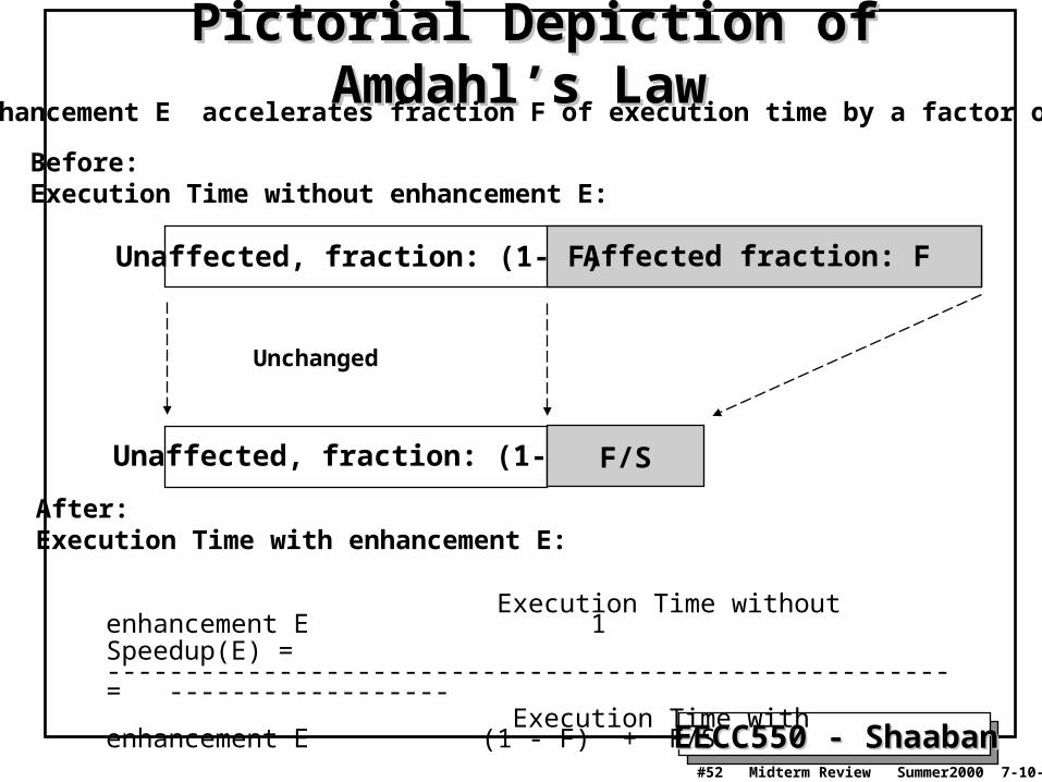
Pictorial Depiction of Amdahl’s LawPictorial Depiction of Amdahl’s Law
Before: Execution Time without enhancement E:
Unaffected, fraction: (1- F)
After: Execution Time with enhancement E:
Enhancement E accelerates fraction F of execution time by a factor of S
Affected fraction: F
Unaffected, fraction: (1- F) F/S
Unchanged
Execution Time without enhancement E 1Speedup(E) = ------------------------------------------------------ = ------------------ Execution Time with enhancement E (1 - F) + F/S

EECC550 - ShaabanEECC550 - Shaaban#53 Midterm Review Summer2000 7-10-2000
Performance Enhancement ExamplePerformance Enhancement Example• For the RISC machine with the following instruction mix given
earlier:Op Freq Cycles CPI(i) % TimeALU 50% 1 .5 23%Load 20% 5 1.0 45%Store 10% 3 .3 14%
Branch 20% 2 .4 18%
• If a CPU design enhancement improves the CPI of load instructions from 5 to 2, what is the resulting performance improvement from this enhancement:
Fraction enhanced = F = 45% or .45
Unaffected fraction = 100% - 45% = 55% or .55
Factor of enhancement = 5/2 = 2.5
Using Amdahl’s Law: 1 1Speedup(E) = ------------------ = --------------------- = 1.37 (1 - F) + F/S .55 + .45/2.5
CPI = 2.2

EECC550 - ShaabanEECC550 - Shaaban#54 Midterm Review Summer2000 7-10-2000
An Alternative Solution Using CPU An Alternative Solution Using CPU EquationEquation
Op Freq Cycles CPI(i) % TimeALU 50% 1 .5 23%Load 20% 5 1.0 45%Store 10% 3 .3 14%
Branch 20% 2 .4 18%
• If a CPU design enhancement improves the CPI of load instructions from 5 to 2, what is the resulting performance improvement from this enhancement:
Old CPI = 2.2
New CPI = .5 x 1 + .2 x 2 + .1 x 3 + .2 x 2 = 1.6
Original Execution Time Instruction count x old CPI x clock cycleSpeedup(E) = ----------------------------------- = ---------------------------------------------------------------- New Execution Time Instruction count x new CPI x clock cycle
old CPI 2.2= ------------ = --------- = 1.37
new CPI 1.6
Which is the same speedup obtained from Amdahl’s Law in the first solution.
CPI = 2.2

EECC550 - ShaabanEECC550 - Shaaban#55 Midterm Review Summer2000 7-10-2000
Performance Enhancement ExamplePerformance Enhancement Example• A program runs in 100 seconds on a machine with multiply operations
responsible for 80 seconds of this time. By how much must the speed of multiplication be improved to make the program four times faster?
100 Desired speedup = 4 = ----------------------------------------------------- Execution Time with enhancement
Execution time with enhancement = 25 seconds
25 seconds = (100 - 80 seconds) + 80 seconds / n
25 seconds = 20 seconds + 80 seconds / n
5 = 80 seconds / n
n = 80/5 = 16
Hence multiplication should be 16 times faster to get a speedup of 4.

EECC550 - ShaabanEECC550 - Shaaban#56 Midterm Review Summer2000 7-10-2000
Extending Amdahl's Law To Multiple EnhancementsExtending Amdahl's Law To Multiple Enhancements
• Suppose that enhancement Ei accelerates a fraction Fi of the execution time by a factor Si and the remainder of the time is unaffected then:
i ii
ii
XSFF
Speedup
Time Execution Original)1
Time Execution Original
)((
i ii
ii S
FFSpeedup
)( )1
1
(
Note: All fractions refer to original execution time.

EECC550 - ShaabanEECC550 - Shaaban#57 Midterm Review Summer2000 7-10-2000
Amdahl's Law With Multiple Enhancements: Amdahl's Law With Multiple Enhancements: ExampleExample
• Three CPU performance enhancements are proposed with the following speedups and percentage of the code execution time affected:
Speedup1 = S1 = 10 Percentage1 = F1 = 20%
Speedup2 = S2 = 15 Percentage1 = F2 = 15%
Speedup3 = S3 = 30 Percentage1 = F3 = 10%
• While all three enhancements are in place in the new design, each enhancement affects a different portion of the code and only one enhancement can be used at a time.
• What is the resulting overall speedup?
• Speedup = 1 / [(1 - .2 - .15 - .1) + .2/10 + .15/15 + .1/30)] = 1 / [ .55 + .0333 ] = 1 / .5833 = 1.71
i ii
ii S
FFSpeedup
)( )1
1
(

EECC550 - ShaabanEECC550 - Shaaban#58 Midterm Review Summer2000 7-10-2000
Pictorial Depiction of ExamplePictorial Depiction of Example Before: Execution Time with no enhancements: 1
After: Execution Time with enhancements: .55 + .02 + .01 + .00333 = .5833
Speedup = 1 / .5833 = 1.71
Note: All fractions refer to original execution time.
Unaffected, fraction: .55
Unchanged
Unaffected, fraction: .55 F1 = .2 F2 = .15 F3 = .1
S1 = 10 S2 = 15 S3 = 30
/ 10 / 30/ 15

EECC550 - ShaabanEECC550 - Shaaban#59 Midterm Review Summer2000 7-10-2000
Major CPU Design StepsMajor CPU Design Steps1 Using independent RTN, write the micro-operations
required for all target ISA instructions.
2 Construct the datapath required by the micro-operations identified in step 1.
3 Identify and define the function of all control signals needed by the datapath.
3 Control unit design, based on micro-operation timing and control signals identified:- Hard-Wired: Finite-state machine implementation- Microprogrammed.

EECC550 - ShaabanEECC550 - Shaaban#60 Midterm Review Summer2000 7-10-2000
Datapath Design StepsDatapath Design Steps• Write the micro-operation sequences required for a number of
representative instructions using independent RTN.
• From the above, create an initial datapath by determining possible destinations for each data source (i.e registers, ALU).– This establishes the connectivity requirements (data paths, or
connections) for datapath components.
– Whenever multiple sources are connected to a single input, a multiplexer of appropriate size is added.
• Find the worst-time propagation delay in the datapath to determine the datapath clock cycle.
• Complete the micro-operation sequences for all remaining instructions adding connections/multiplexers as needed.

EECC550 - ShaabanEECC550 - Shaaban#61 Midterm Review Summer2000 7-10-2000
Single Cycle MIPS DatapathSingle Cycle MIPS DatapathNecessary multiplexors and control lines are identified here:

EECC550 - ShaabanEECC550 - Shaaban#62 Midterm Review Summer2000 7-10-2000
R-Type Register-Register TimingR-Type Register-Register Timing
32Result
ALUctr
Clk
busW
RegWr
3232
busA
32busB
5 5 5
Rw Ra Rb32 32-bitRegisters
Rs RtRd
AL
U
Clk
PC
Rs, Rt, Rd,Op, Func
Clk-to-Q
ALUctr
Instruction Memory Access Time
Old Value
New Value
RegWr Old Value
New Value
Delay through Control Logic
busA, B
Register File Access TimeOld Value
New Value
busWALU Delay
Old Value
New Value
Old Value
New Value
New ValueOld Value
Register WriteOccurs Here

EECC550 - ShaabanEECC550 - Shaaban#63 Midterm Review Summer2000 7-10-2000
Clk
PC
Rs, Rt, Rd,Op, Func
Clk-to-Q
ALUctr
Instruction Memoey Access Time
Old Value New Value
RegWr Old Value New Value
Delay through Control Logic
busA
Register File Access Time
Old Value New Value
busB
ALU Delay
Old Value New Value
Old Value New Value
New ValueOld Value
ExtOp Old Value New Value
ALUSrc Old Value New Value
MemtoReg Old Value New Value
Address Old Value New Value
busW Old Value New
Delay through Extender & Mux
RegisterWrite Occurs
Data Memory Access Time
Worst Case Timing (Load)Worst Case Timing (Load)
EECC550 - ShaabanEECC550 - Shaaban#64 Midterm Review Summer2000 7-10-2000
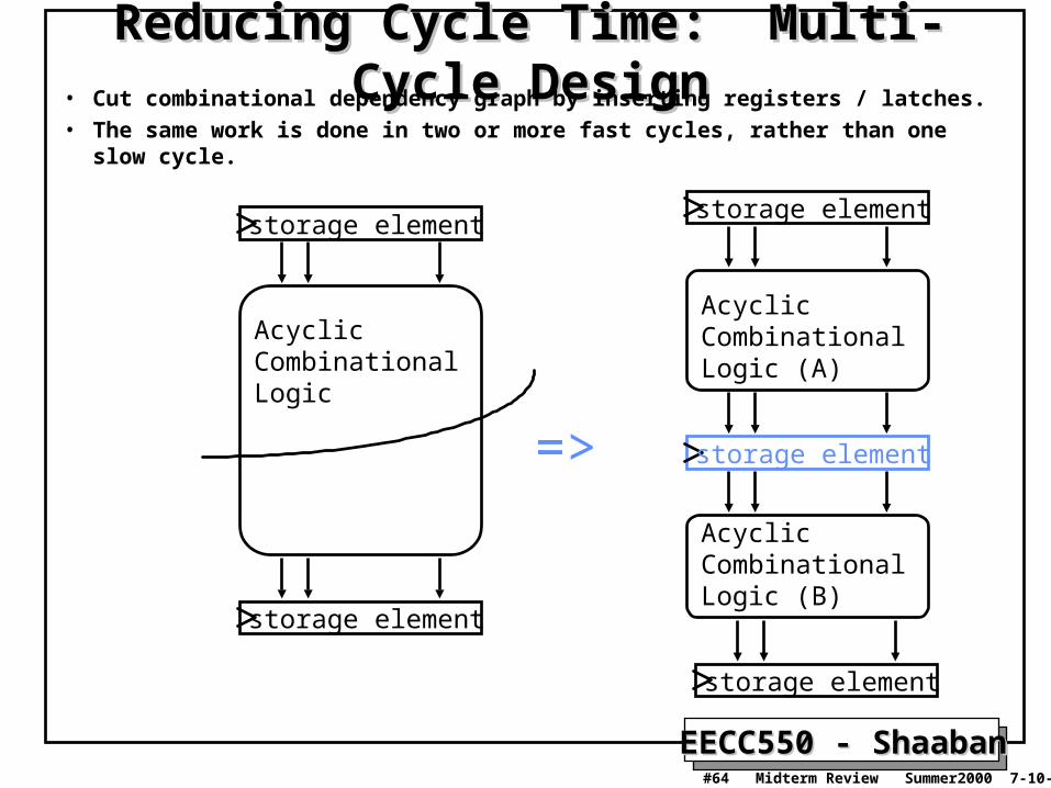
Reducing Cycle Time: Multi-Cycle DesignReducing Cycle Time: Multi-Cycle Design• Cut combinational dependency graph by inserting registers / latches.• The same work is done in two or more fast cycles, rather than one slow cycle.
storage element
Acyclic CombinationalLogic
storage element
storage element
Acyclic CombinationalLogic (A)
storage element
storage element
Acyclic CombinationalLogic (B)
=>

EECC550 - ShaabanEECC550 - Shaaban#65 Midterm Review Summer2000 7-10-2000
Example Multi-cycle DatapathExample Multi-cycle Datapath
PC
Nex
t P
C
Ope
rand
Fet
ch
Ext
ALU Reg
. F
ile
Mem
Acc
ess
Dat
aM
em
Inst
ruct
ion
Fet
ch
Res
ult
Sto
re
AL
Uct
r
Reg
Dst
AL
US
rc
Ext
Op
nPC
_sel
Reg
Wr
Mem
Wr
Mem
Rd
IR
A
B
R
M
RegFile
Mem
ToR
eg
Equ
al
Registers added:
IR: Instruction registerA, B: Two registers to hold operands read from register file.R: or ALUOut, holds the output of the ALUM: or Memory data register (MDR) to hold data read from data memory

EECC550 - ShaabanEECC550 - Shaaban#66 Midterm Review Summer2000 7-10-2000
Operations In Each CycleOperations In Each Cycle
Instruction Fetch
Instruction Decode
Execution
Memory
WriteBack
R-Type
IR Mem[PC]
A R[rs]
B R[rt]
R A + B
R[rd] R
PC PC + 4
Logic Immediate
IR Mem[PC]
A R[rs]
R A OR ZeroExt[imm16]
R[rt] R
PC PC + 4
Load
IR Mem[PC]
A R[rs]
R A + SignEx(Im16)
M Mem[R]
R[rd] M
PC PC + 4
Store
IR Mem[PC]
A R[rs]
B R[rt]
R A + SignEx(Im16)
Mem[R] B
PC PC + 4
Branch
IR Mem[PC]
A R[rs]
B R[rt]
If Equal = 1
PC PC + 4 +
(SignExt(imm16) x4)
else
PC PC + 4

EECC550 - ShaabanEECC550 - Shaaban#67 Midterm Review Summer2000 7-10-2000
Control Specification For Multi-cycle CPUControl Specification For Multi-cycle CPUFinite State Machine (FSM)Finite State Machine (FSM)
IR MEM[PC]
R-type
A R[rs]B R[rt]
R A fun B
R[rd] RPC PC + 4
R A or ZX
R[rt] RPC PC + 4
ORi
R A + SX
R[rt] MPC PC + 4
M MEM[R]
LW
R A + SX
MEM[R] BPC PC + 4
BEQ & Equal
BEQ & ~Equal
PC PC + 4 PC PC + SX || 00
SW
“instruction fetch”
“decode / operand fetch”
Exe
cute
Mem
ory
Wri
te-b
ack
To instruction fetch
To instruction fetchTo instruction fetch

EECC550 - ShaabanEECC550 - Shaaban#68 Midterm Review Summer2000 7-10-2000
Alternative Multiple Cycle Datapath (In Textbook)
•Shared instruction/data memory unit• A single ALU shared among instructions• Shared units require additional or widened multiplexors• Temporary registers to hold data between clock cycles of the instruction:
• Additional registers: Instruction Register (IR), Memory Data Register (MDR), A, B, ALUOut

EECC550 - ShaabanEECC550 - Shaaban#69 Midterm Review Summer2000 7-10-2000
Operations In Each CycleOperations In Each Cycle
Instruction Fetch
Instruction Decode
Execution
Memory
WriteBack
R-Type
IR Mem[PC]PC PC + 4
A R[rs]
B R[rt]
ALUout PC + (SignExt(imm16) x4)
ALUout A + B
R[rd] ALUout
Logic Immediate
IR Mem[PC]PC PC + 4
A R[rs]
B R[rt]
ALUout PC +
(SignExt(imm16) x4)
ALUout
A OR ZeroExt[imm16]
R[rt] ALUout
Load
IR Mem[PC]PC PC + 4
A R[rs]
B R[rt]
ALUout PC +
(SignExt(imm16) x4)
ALUout
A + SignEx(Im16)
M Mem[ALUout]
R[rd] Mem
Store
IR Mem[PC]PC PC + 4
A R[rs]
B R[rt]
ALUout PC +
(SignExt(imm16) x4)
ALUout
A + SignEx(Im16)
Mem[ALUout] B
Branch
IR Mem[PC]PC PC + 4
A R[rs]
B R[rt]
ALUout PC +
(SignExt(imm16) x4)
If Equal = 1
PC ALUout
EECC550 - ShaabanEECC550 - Shaaban#70 Midterm Review Summer2000 7-10-2000
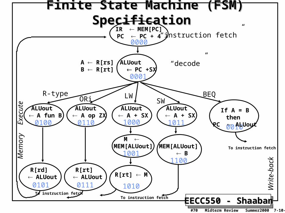
Finite State Machine (FSM) SpecificationFinite State Machine (FSM) SpecificationIR MEM[PC]
PC PC + 4
R-type
ALUout A fun B
R[rd] ALUout
ALUout A op ZX
R[rt] ALUout
ORiALUout
A + SX
R[rt] M
M MEM[ALUout]
LW
ALUout A + SX
MEM[ALUout] B
SW
“instruction fetch”
“decode”
Exe
cute
Mem
ory
Writ
e-ba
ck
0000
0001
0100
0101
0110
0111
1000
1001
1010
1011
1100
BEQ
0010
If A = B then PC ALUout
A R[rs]B R[rt]
ALUout PC +SX
To instruction fetch
To instruction fetchTo instruction fetch

EECC550 - ShaabanEECC550 - Shaaban#71 Midterm Review Summer2000 7-10-2000
MIPS Multi-cycle Datapath MIPS Multi-cycle Datapath Performance EvaluationPerformance Evaluation
• What is the average CPI?– State diagram gives CPI for each instruction type
– Workload below gives frequency of each type
Type CPIi for type Frequency CPIi x freqIi
Arith/Logic 4 40% 1.6
Load 5 30% 1.5
Store 4 10% 0.4
branch 3 20% 0.6
Average CPI: 4.1
Better than CPI = 5 if all instructions took the same number of clock cycles (5).

EECC550 - ShaabanEECC550 - Shaaban#72 Midterm Review Summer2000 7-10-2000
Microprogrammed ControlMicroprogrammed Control• Finite state machine control for a full set of instructions is very complex,
and may involve a very large number of states:– Slight microoperation changes require new FSM controller.
• Microprogramming: Designing the control as a program that implements the machine instructions.
• A microprogam for a given machine instruction is a symbolic representation of the control involved in executing the instruction and is comprised of a sequence of microinstructions.
•
• Each microinstruction defines the set of datapath control signals that must asserted (active) in a given state or cycle.
• The format of the microinstructions is defined by a number of fields each responsible for asserting a set of control signals.
• Microarchitecture:– Logical structure and functional capabilities of the hardware as seen by
the microprogrammer.

EECC550 - ShaabanEECC550 - Shaaban#73 Midterm Review Summer2000 7-10-2000
Types of “branching”• Set state to 0 (fetch)• Dispatch i (state 1)• Use incremented address (seq) state number 2
Opcode
State Reg
Microinstruction Address
Inputs
Outputs Control Signal Fields
Microprogram Storage
ROM/PLA
MulticycleDatapath
1
Address Select Logic
Adder
MicroprogramCounter, MicroPC
SequencingControlField
Microprogrammed Control UnitMicroprogrammed Control Unit

EECC550 - ShaabanEECC550 - Shaaban#74 Midterm Review Summer2000 7-10-2000
Microinstruction Field ValuesMicroinstruction Field ValuesField Name Values for Field Function of Field with Specific Value
ALU Add ALU addsSubt. ALU subtractsFunc code ALU does function codeOr ALU does logical OR
SRC1 PC 1st ALU input = PCrs 1st ALU input = Reg[rs]
SRC2 4 2nd ALU input = 4Extend 2nd ALU input = sign ext. IR[15-0]Extend0 2nd ALU input = zero ext. IR[15-0] Extshft 2nd ALU input = sign ex., sl IR[15-0]rt 2nd ALU input = Reg[rt]
destination rd ALU Reg[rd] ALUout rt ALU Reg[rt] ALUout
rt Mem Reg[rt] Mem
Memory Read PC Read memory using PCRead ALU Read memory using ALU outputWrite ALU Write memory using ALU output, value B
Memory register IR IR Mem
PC write ALU PC ALUALUoutCond IF ALU Zero then PC ALUout
Sequencing Seq Go to sequential µinstructionFetch Go to the first microinstructionDispatch i Dispatch using ROM.

EECC550 - ShaabanEECC550 - Shaaban#75 Midterm Review Summer2000 7-10-2000
Microprogram for The Control UnitMicroprogram for The Control UnitLabel ALU SRC1 SRC2 Dest. Memory Mem. Reg. PC Write Sequencing
Fetch: Add PC 4 Read PC IR ALU SeqAdd PC Extshft Dispatch
Lw: Add rs Extend Seq Read ALU Seq
rt MEM Fetch
Sw: Add rs Extend SeqWrite ALU Fetch
Rtype: Func rs rt Seqrd ALU Fetch
Beq: Subt. rs rt ALUoutCond. Fetch
Ori: Or rs Extend0 Seqrt ALU Fetch

EECC550 - ShaabanEECC550 - Shaaban#76 Midterm Review Summer2000 7-10-2000
Exceptions Handling in MIPSExceptions Handling in MIPS• Exceptions: Events Other than branches or jumps that change the
normal flow of instruction execution.• Two main types: Interrupts, Traps.
– An interrupt usually comes from outside the processor (I/O devices) to get the CPU’s attention to start a service routine.
– A trap usually originates from an event within the CPU (Arithmetic overflow, undefined instruction) and initiates an exception handling routine usually by the operating system.
• The current MIPS implementation being considered can be extended to handle exceptions by adding two additional registers and the associated control lines:
– EPC: A 32 bit register to hold the address of the affected instruction– Cause: A register used to record the cause of the exception.
In this implementation only the low-order bit is used to encode the two handled exceptions: undefined instruction = 0
overflow = 1
• Two additional states are added to the control finite state machine to handle these exceptions.

EECC550 - ShaabanEECC550 - Shaaban#77 Midterm Review Summer2000 7-10-2000
The MIPS Multicycle Datapath With The MIPS Multicycle Datapath With Exception Handling AddedException Handling Added

EECC550 - ShaabanEECC550 - Shaaban#78 Midterm Review Summer2000 7-10-2000
FSM Control Specification To Handle ExceptionsFSM Control Specification To Handle ExceptionsIR MEM[PC]
PC PC + 4
R-type
ALUout A fun B
R[rd] ALUout
ALUout A op ZX
R[rt] ALUout
ORiALUout
A + SX
R[rt] M
M MEM[ALUout]
LW
ALUout A + SX
MEM[ALUout] B
SW
“instruction fetch”
“decode”
Exe
cute
Mem
ory
Writ
e-ba
ck
0000
0001
0100
0101
0110
0111
1000
1001
1010
1011
1100
A R[rs]B R[rt]
ALUout PC +SX EPC PC - 4
PC exp_addrcause 10 (RI)
undefined instruction
EPC PC - 4PC exp_addrcause 12 (Ovf)
overflow
BEQ
0010
If A = B then PC ALUout
To instruction fetch
To instruction fetchTo instruction fetch