ee360: lecture 7 outline cellular system capacity and ase announcements summary due next week...
TRANSCRIPT

EE360: Lecture 7 OutlineCellular System Capacity
and ASE
AnnouncementsSummary due next week
CapacityArea Spectral EfficiencyDynamic Resource Allocation

8C32810.43-Cimini-7/98
Review of Cellular Lecture
Design considerations: Spectral sharing, reuse, cell size
Evolution: 1G to 2G to 3G to 4G and beyond Multiuser Detection in cellular
MIMO in CellularMultiuser MIMO/OFDMMultiplexing/diversity/IC tradeoffsDistributed antenna systemsVirtual MIMO

Cellular System Capacity
Shannon CapacityShannon capacity does no incorporate reuse
distance.Wyner capacity: capacity of a TDMA systems
with joint base station processing
User Capacity Calculates how many users can be supported
for a given performance specification.Results highly dependent on traffic, voice
activity, and propagation models.Can be improved through interference
reduction techniques.
Area Spectral EfficiencyCapacity per unit area
In practice, all techniques have roughly the same capacity for voice, butflexibility of OFDM/MIMO supports more heterogeneous users

Defining Cellular Capacity
Shannon-theoretic definition Multiuser channels typically assume user
coordination and joint encoding/decoding strategies Can an optimal coding strategy be found, or should
one be assumed (i.e. TD,FD, or CD)? What base station(s) should users talk to? What assumptions should be made about base
station coordination? Should frequency reuse be fixed or optimized? Is capacity defined by uplink or downlink? Capacity becomes very dependent on propagation
model
Practical capacity definitions (rates or users) Typically assume a fixed set of system parameters Assumptions differ for different systems:
comparison hard Does not provide a performance upper bound
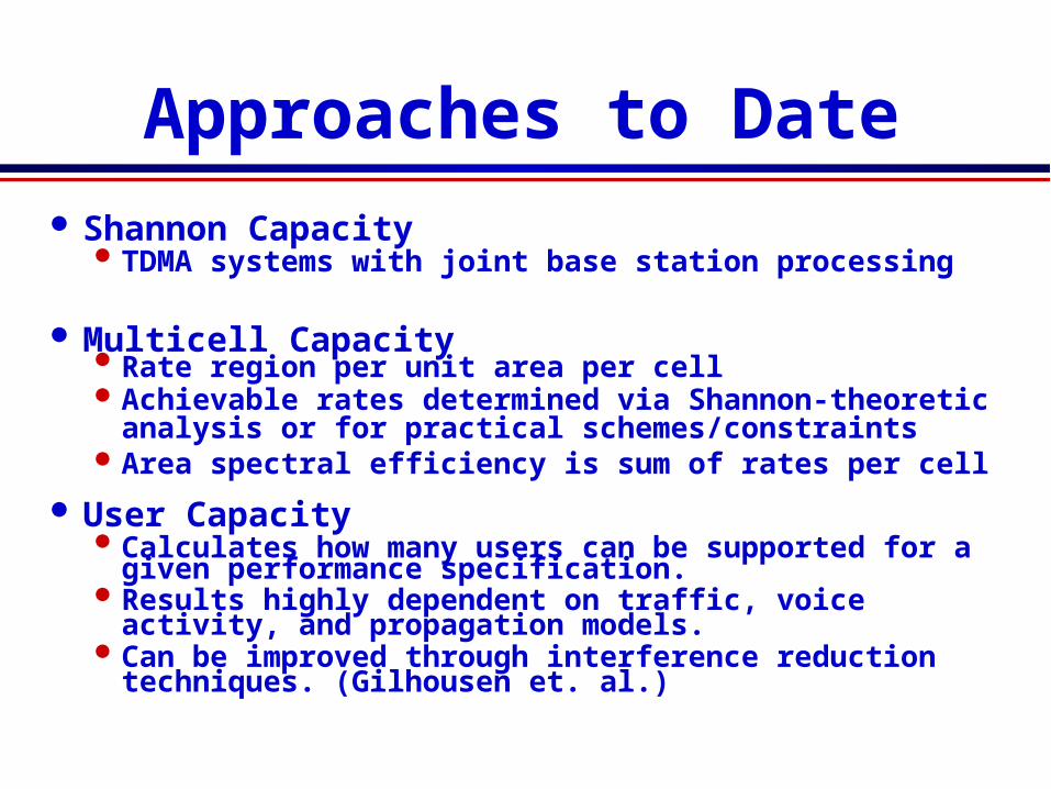
Approaches to Date Shannon Capacity
TDMA systems with joint base station processing
Multicell CapacityRate region per unit area per cellAchievable rates determined via Shannon-theoretic
analysis or for practical schemes/constraintsArea spectral efficiency is sum of rates per cell
User Capacity Calculates how many users can be supported for a
given performance specification.Results highly dependent on traffic, voice activity,
and propagation models.Can be improved through interference reduction
techniques. (Gilhousen et. al.)

Wyner Uplink Capacity
Linear or hexagonal cells
Received signal at base station (N total users)
Propagation for out-of-cell interference captured by Average power constraint: E
Capacity CN defined as largest achievable rate (N
users)

Linear Array
Theorem:
for
Optimal scheme uses TDMA within a cell - Users transmit in 1/K timeslots; power KP
Treats co-channel signals as interference:
)(*lim CCNN

Results Alternate TDMA
CDMA w/ MMSE

9
• Channel Reuse in Cellular SystemsChannel Reuse in Cellular Systems
• Motivation: power falloff with transmission distanceMotivation: power falloff with transmission distance
• Pro: increase system spectral efficiencyPro: increase system spectral efficiency
• Con: co-channel interference (CCI) Con: co-channel interference (CCI)
• “ “Channel”: time slot, frequency band, (semi)-orthogonal code ...Channel”: time slot, frequency band, (semi)-orthogonal code ...
• Cellular Systems with different multiple-access techniquesCellular Systems with different multiple-access techniques
• CDMA (IS-95, CDMA2000): weak CCI, channel reuse in every cellCDMA (IS-95, CDMA2000): weak CCI, channel reuse in every cell
• codes designed with a single and narrow autocorrelation peak codes designed with a single and narrow autocorrelation peak
• TDMA (GSM), FDMA (AMPS): much stronger CCITDMA (GSM), FDMA (AMPS): much stronger CCI
• a minimum reuse distance required to support target SINRa minimum reuse distance required to support target SINR
• Channel reuse: traditionally a fixed system design parameterChannel reuse: traditionally a fixed system design parameter
Channel Reuse in Cellular Systems

10
• TradeoffTradeoff
• Large reuse distance reduces CCILarge reuse distance reduces CCI
• Small reuse distance increases bandwidth allocationSmall reuse distance increases bandwidth allocation
• Related workRelated work
• [Frodigh 92] Propagation model with path-loss only[Frodigh 92] Propagation model with path-loss only
channel assignment based on sub-cell compatibilitychannel assignment based on sub-cell compatibility
• [Horikawa 05] Adaptive guard interval control[Horikawa 05] Adaptive guard interval control
special case of adaptive channel reuse in TDMA systemsspecial case of adaptive channel reuse in TDMA systems
• Current workCurrent work
• Propagation models incorporating Propagation models incorporating time variationtime variation of wireless channels of wireless channels
static (AWGN) channel, fast fading and slow fadingstatic (AWGN) channel, fast fading and slow fading
• Channel reuse in Channel reuse in cooperative cellular systemscooperative cellular systems (network MIMO) (network MIMO)
compare with compare with single base station processingsingle base station processing
Adaptive Channel Reuse

11
• Linear cellular array, one-dimensional, downlink, single cell Linear cellular array, one-dimensional, downlink, single cell processingprocessing
best models the system along a highway [Wyner 1994]best models the system along a highway [Wyner 1994]
• Full cooperation leads to fundamental performance limitFull cooperation leads to fundamental performance limit
• More practical scheme: adjacent base station cooperationMore practical scheme: adjacent base station cooperation
System Model

12
Channel Assignment
• Intra-cell FDMA, K users per cellIntra-cell FDMA, K users per cell, total bandwidth in the system K·Bmtotal bandwidth in the system K·Bm
• Bandwidth allocated to each user Bandwidth allocated to each user
• maxium bandwidth Bm, corresponding to channel reuse in each cell maxium bandwidth Bm, corresponding to channel reuse in each cell
• may opt for a fraction of bandwidth, based on channel strengthmay opt for a fraction of bandwidth, based on channel strength
• increased reuse distance, reduced CCI & possibly higher rateincreased reuse distance, reduced CCI & possibly higher rate

13
• Path loss only, Path loss only, receive powerreceive power
A: path loss at unit distanceA: path loss at unit distance
γγ : path-loss exponent : path-loss exponent
• Receive SINRReceive SINR
L: cell radius. NL: cell radius. N00: noise power: noise power
• Optimal reuse factorOptimal reuse factor
tAP
NLL dd
d
022
Single Base Station Transmission: AWGN
dPAdP tr )(
),(1log maxarg dBm
),( d
• ObservationsObservations
• Mobile close to base station -> strong channel, small reuse distanceMobile close to base station -> strong channel, small reuse distance
• Reuse factor changes (1 -> ½) at transition distance dReuse factor changes (1 -> ½) at transition distance dTT = 0.62 mile = 0.62 mile

14
• Environment with rich scattersEnvironment with rich scatters
• Applies if channel coherence time shorter Applies if channel coherence time shorter than delay constraintthan delay constraint
• Receive powerReceive power
g: exponentially distributed r.v.g: exponentially distributed r.v.
• Optimal reuse factorOptimal reuse factor
• Lower bound: Lower bound: random signalrandom signal
Upper bound: Upper bound: random interferencerandom interference
Rayleigh Fast Fading Channel
dPgAP tr
),,(1log maxarg gdB gm E
• ObservationsObservations
• AWGN and fast fading yield similar performanceAWGN and fast fading yield similar performance
reuse factor changes (1 -> ½)reuse factor changes (1 -> ½) at transition distance dat transition distance dTT = 0.65 mile = 0.65 mile
• Both “sandwiched” by same upper/lower bounds (small gap in between) Both “sandwiched” by same upper/lower bounds (small gap in between)

15
• Stringent delay constraint, entire Stringent delay constraint, entire codeword falls in one fading statecodeword falls in one fading state
• Optimal reuse factorOptimal reuse factor
• Compare with AWGN/slow fading:Compare with AWGN/slow fading:
optimal reuse factor only depends on optimal reuse factor only depends on distance between mobile and base stationdistance between mobile and base station
Rayleigh Slow Fading Channel
),,(1log maxarg gdBm
• ObservationsObservations
• Optimal reuse factor random at each distance, also depends on fadingOptimal reuse factor random at each distance, also depends on fading
• Larger reuse distance (1/Larger reuse distance (1/ττ > 2) needed when mobiles close to cell edge > 2) needed when mobiles close to cell edge
16
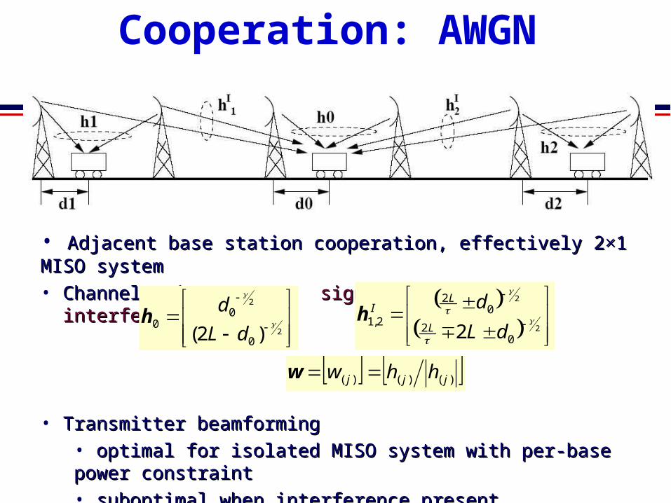
• Adjacent base station cooperation, effectively 2×1 MISO systemAdjacent base station cooperation, effectively 2×1 MISO system
• Channel gain vectors: Channel gain vectors: signal interferencesignal interference
• Transmitter beamformingTransmitter beamforming
• optimal for isolated MISO system with per-base power constraintoptimal for isolated MISO system with per-base power constraint
• suboptimal when interference presentsuboptimal when interference present
• an initial choice to gain insight into system designan initial choice to gain insight into system design
Base Station Cooperation: AWGN
2
2
)2( 0
00
dL
dh
2
2
02
02
2,12
dL
dL
LI
h
)()()( jjj hhw w

17
• no reuse channel in adjacent cell: to no reuse channel in adjacent cell: to avoid base station serving user and avoid base station serving user and interferer at the same timeinterferer at the same time
• reuse factor ½ optimal at all d: reuse factor ½ optimal at all d: suppressing CCI without overly shrinking suppressing CCI without overly shrinking the bandwidth allocation the bandwidth allocation
• bandwidth reduction (1-> ½) over-bandwidth reduction (1-> ½) over-shadows benefit from cooperationshadows benefit from cooperation
Performance Comparison
ObservationsObservations
• Advantage of cooperation over single cell transmission: only prominent when users Advantage of cooperation over single cell transmission: only prominent when users share the channel; limited with intra-cell TD/FD [Liang 06]share the channel; limited with intra-cell TD/FD [Liang 06]
• Remedy: allow more base stations to cooperateRemedy: allow more base stations to cooperate
in the extreme case of full cooperation, channel reuse in every cell in the extreme case of full cooperation, channel reuse in every cell
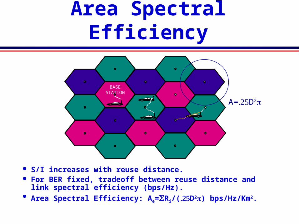
Area Spectral Efficiency
BASESTATION
S/I increases with reuse distance. For BER fixed, tradeoff between reuse distance and link
spectral efficiency (bps/Hz). Area Spectral Efficiency: Ae=Ri/(D2) bps/Hz/Km2.
A=D2 =

ASE with Adaptive Modulation
Users adapt their rates (and powers) relative to S/I variation.
S/I distribution for each user based on propagation and interference models.
Computed for extreme interference conditions. Simulated for average interference conditions.
The maximum rate Ri for each user in a cell is computed from its S/I distribution. For narrowband system use adaptive MQAM analysis
d d iS S /

Propagation Model
Two-slope path loss model:
Slow fading model: log-normal shadowing
Fast fading model: Nakagami-mModels Rayleigh and approximates Ricean.
ASE maximized with reuse distance of one!Adaptive modulation compensate for
interference
S dK
d d gS
r a bt( )
( / ),
1

ASE vs. Cell Radius
Cell Radius R [Km]
101
100A
vera
ge
Are
a S
pe
ctra
l E
ffic
ien
cy[B
ps/
Hz/
Km
2 ]
0.1 0.2 0.3 0.4 0.5 0.6 0.7 0.8 0.9 1
D=4R
D=6R
D=8R
fc=2 GHz

Distributed Antennas (DAS) in Cellular
Basic Premise:Distribute BS antennas throughout cell
Rather than just at the centerAntennas connect to BS through
wireless/wireline links
Performance benefitsCapacityCoveragePower consumption
DAS

1p
2p 3p
4p
5p6p
7p
Average Ergodic Rate Assume full CSIT at BS of gains for all antenna ports Downlink is a MIMO broadcast channel with full CSIR Expected rate is
Average over user location and shadowing
DAS optimizationWhere to place antennasGoal: maximize ergodic rate
2
12 ),(1log)(
N
Ii
ishucsit upD
fSEEPC

Interference Effect Impact of intercell interference
is the interference coefficient from cell j Autocorrelation of neighboring cell codes for CDMA
systems Set to 1 for LTE(OFDM) systems with frequency
reuse of one.
6
1 1
2
1
),(
),(
j
N
i ji
ij
N
ii
i
upD
fupD
f
SINR
j

Interference Effect
The optimal layout shrinks towards the center of the cell as the interference coefficient increases

Area Spectral Efficiency
Average user rate/unit bandwidth/unit area (bps/Hz/Km2) Captures effect of cell size on spectral efficiency
and interference• ASE typically increases as cell size decreases
• Optimal placement leads to much higher gains as cell size shrinks vs. random placement

Summary Wireless data/multimedia are main drivers for
future generations of cellular systems.Killer application unknown; how will cellular users
access the Internet; will cellular or WLANs prevail.
Efficient systems are interference-limited Interference reduction key to high system capacity
Adaptive techniques in cellular can improve significantly performance and capacity
MIMO a powerful technique, but impact on out-of-cell interference and implementation unknown.

Dynamic Resource Allocation
Allocate resources as user and network conditions change
Resources:ChannelsBandwidthPowerRateBase stationsAccess
Optimization criteriaMinimize blocking (voice only systems)Maximize number of users (multiple classes)Maximize “revenue”: utility function
Subject to some minimum performance for each user
BASESTATION

Dynamic Channel Allocation
Fixed channel assignments are inefficient Channels in unpopulated cells underutilized Handoff calls frequently dropped
Channel Borrowing A cell may borrow free channels from neighboring cells Changes frequency reuse plan
Channel Reservations Each cell reserves some channels for handoff calls Increases blocking of new calls, but fewer dropped calls
Dynamic Channel Allocation Rearrange calls to pack in as many users as possible without
violating reuse constraints Very high complexity
“DCA is a 2G/4G problem”
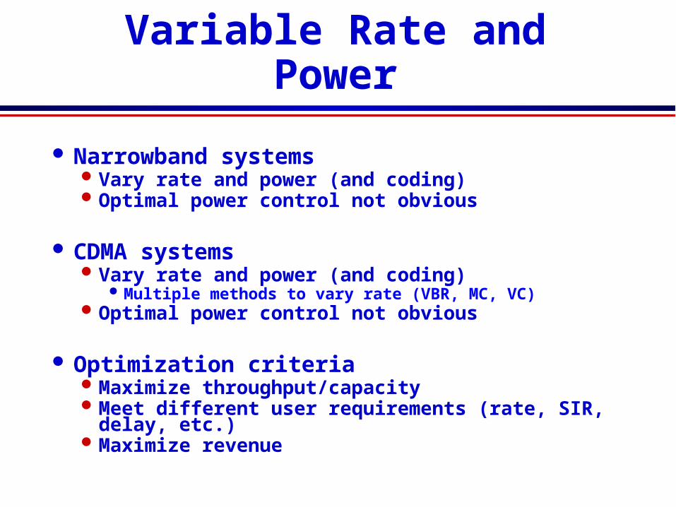
Variable Rate and Power
Narrowband systemsVary rate and power (and coding)Optimal power control not obvious
CDMA systemsVary rate and power (and coding)
Multiple methods to vary rate (VBR, MC, VC)Optimal power control not obvious
Optimization criteriaMaximize throughput/capacityMeet different user requirements (rate, SIR,
delay, etc.)Maximize revenue

Multicarrier CDMA Multicarrier CDMA combines OFDM and CDMA
Idea is to use DSSS to spread a narrowband signal and then send each chip over a different subcarrierDSSS time operations converted to frequency domain
Greatly reduces complexity of SS systemFFT/IFFT replace synchronization and despreading
More spectrally efficient than CDMA due to the overlapped subcarriers in OFDM
Multiple users assigned different spreading codesSimilar interference properties as in CDMA

Optimize power and rate adaptation in a CDMA systemGoal is to minimize transmit
power
Each user has a required QoS Required effective data rate
Rate and Power Control in CDMA*
*Simultaneous Rate and Power Control in MultirateMultimedia CDMA Systems,” S. Kandukuri and S. Boyd

System Model: General
Single cell CDMA
Uplink multiple access channel
Different channel gains
System supports multiple rates

System Model: Parameters
ParametersN = number of mobiles Pi = power transmitted by mobile iRi = raw data rate of mobile iW = spread bandwidth
QoS requirement of mobile i,
i, is the effective data rate)1( eiii PR

System Model: Interference
Interference between users represented by cross correlations
between codes, Cij
Gain of path between mobile i and
base station, Li
Total interfering effect of mobile j on
mobile i, Gij is ijiij CLG

SIR Model (neglect noise)
ijjij
iiii PG
PGSIR
i
i
io
bi R
WSIR
I
E

QoS Formula
Probability of error is a
function of IFormula depends on the
modulation scheme
Simplified Pe expression
QoS formula
iei cP
1
i
ieii R
WSIRPR 1

SolutionObjective: Minimize sum of mobile powers
subject to QoS requirements of all mobiles
Technique: Geometric programmingA non-convex optimization problem is cast as
a convex optimization problem
Convex optimizationObjective and constraints are all convexCan obtain a global optimum or a proof that
the set of specifications is infeasibleEfficient implementation

Problem Formulation
Minimize 1TP (sum of powers)
Subject to
Can also add constraints such as
ii
iei R
WSIRPR
1
threshi RR 0P
minPPi maxPPi

Results
Sum of powers transmitted vs interference

Results
QoS vs. interference