ee330 project 5 the integrated circuit of an automatic
TRANSCRIPT
1
EE330 Project 5
The Integrated Circuit of an Automatic
Washer Control System
Zheng Luo
Mat Huss

2
INDEX
Introduction………………………………………………………………………3
Procedure…………………………………………………………………………3
Results and Analysis………………………………………………………………3
Simulations…………………………………………………………………3
Schematic and Symbol …………………………………………………… 6
Layout………………………………………………………………………7
Conclusion ……………………………………………………………………… 10
Appendix 1 ……………………………………………………………………… 11
Appendix 2 ……………………………………………………………………… 19
3
Introduction
This project is for the design of an integrated circuit that can be used to control an
automatic washer system. The design includes layout and post-layout simulation
results. The outputs that control the mechanical parts of the machine are Boolean
signals that come out of a minimum-sized digital inverter.
Procedure
Firstly, the Verilog code is written to achieve all of the functions that are needed
to control an automatic washer; and the test bench and simulations are used to
verify that the logic can work well.
Secondly, use the GUI window of Cadence® to synthesize the Verilog and get the
schematic in the GUI window. Since the code is good, the schematic can be
imported into the library of Cadence®; and a symbol for that circuit is generated.
Thirdly, use the Encounter to synthesize the RTL code again and then use layout
tools to generate the layout. Since no geometry and connectivity error appears,
the layout can be saved and imported to the library of Cadence®. The layout is
valid since it passes the verification.
Results and Analysis
Inputs Pins: Start (1), Mode (4), Pause (1), Clock (1).
Output Pins: Start LED (1), Mode LEDs (4), Buzzer (1), Washing Control Signals –
Fill (1) and Spin (1) and Control Signals (4), 3-Digit Display (10).
1. Simulations
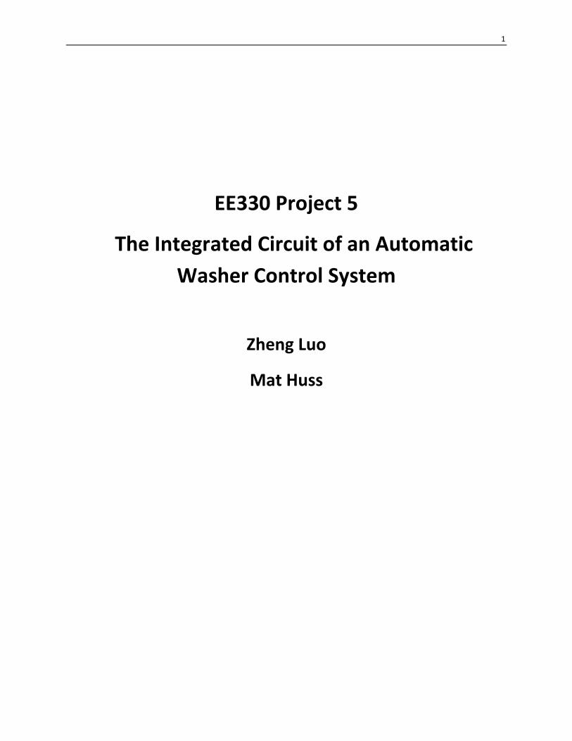
Taking into account the given inputs and outputs, the goal was to work with how
to get from the inputs such as start and mode and get to the outputs like fill and
spin. We then tested it to show all modes worked including pausing of these
modes. Figures 1 through 4 are the simulation results.
In these figures, there are six states in total (five working states plus one initial
state); and all signals of states have been already encoded. 7-segment Display
signals have been already decoded. All of other outputs work as they are. For the
specification of each state or display, see the attached code.
4
Figure 1: Mode 1 Simulation
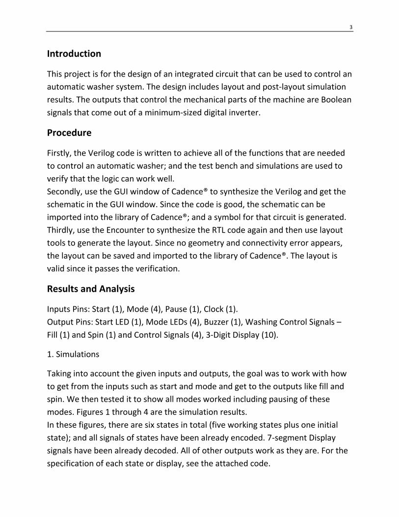
Figure 2: Mode 2 Simulation
5
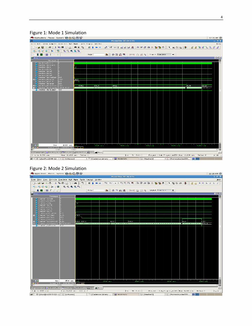
Figure 3: Mode 3 Simulation
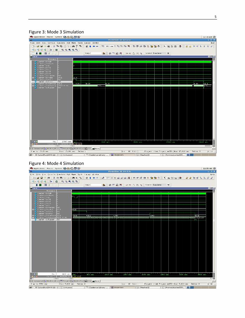
Figure 4: Mode 4 Simulation
6
Note: in mode 4, there are only five states in total because the second state of
mode 4 is of zero minute.
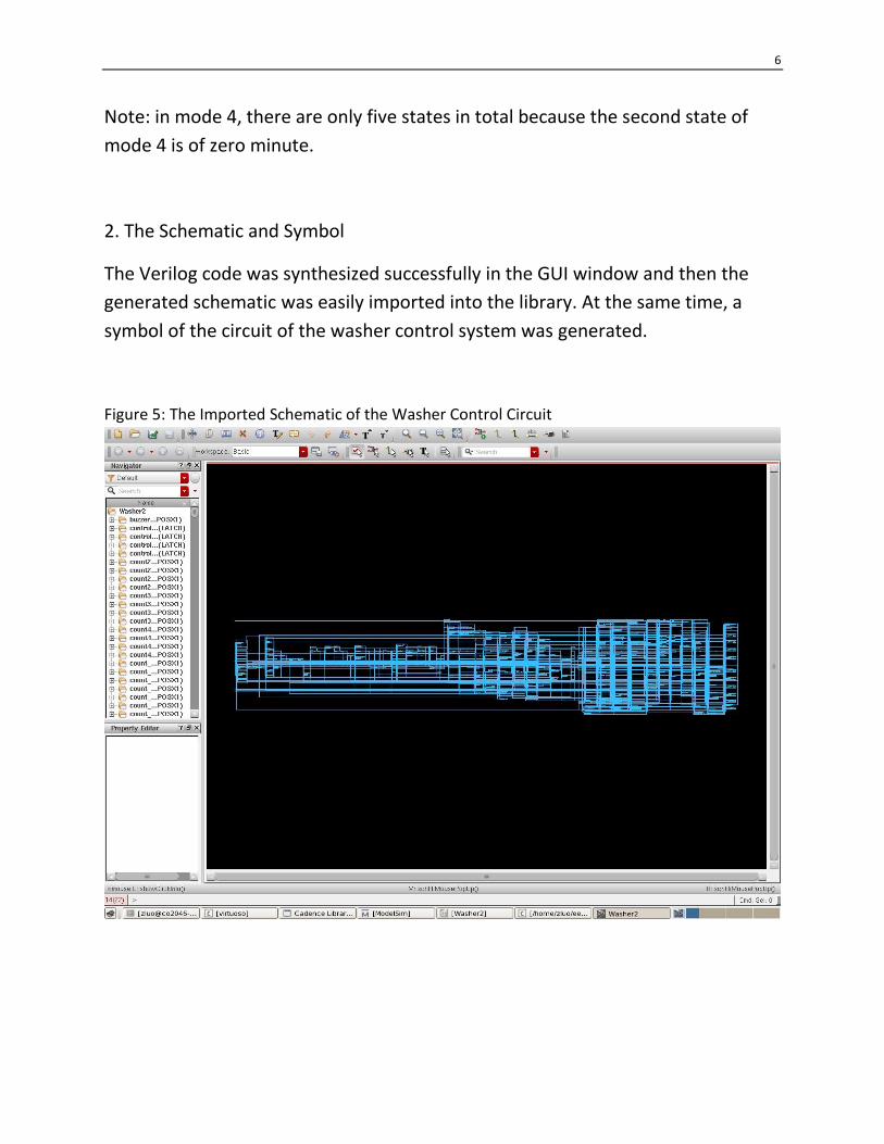
2. The Schematic and Symbol
The Verilog code was synthesized successfully in the GUI window and then the
generated schematic was easily imported into the library. At the same time, a
symbol of the circuit of the washer control system was generated.
Figure 5: The Imported Schematic of the Washer Control Circuit
7
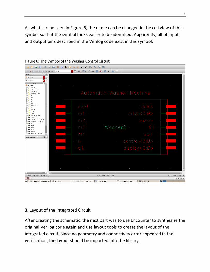
As what can be seen in Figure 6, the name can be changed in the cell view of this
symbol so that the symbol looks easier to be identified. Apparently, all of input
and output pins described in the Verilog code exist in this symbol.
Figure 6: The Symbol of the Washer Control Circuit
3. Layout of the Integrated Circuit
After creating the schematic, the next part was to use Encounter to synthesize the
original Verilog code again and use layout tools to create the layout of the
integrated circuit. Since no geometry and connectivity error appeared in the
verification, the layout should be imported into the library.
8
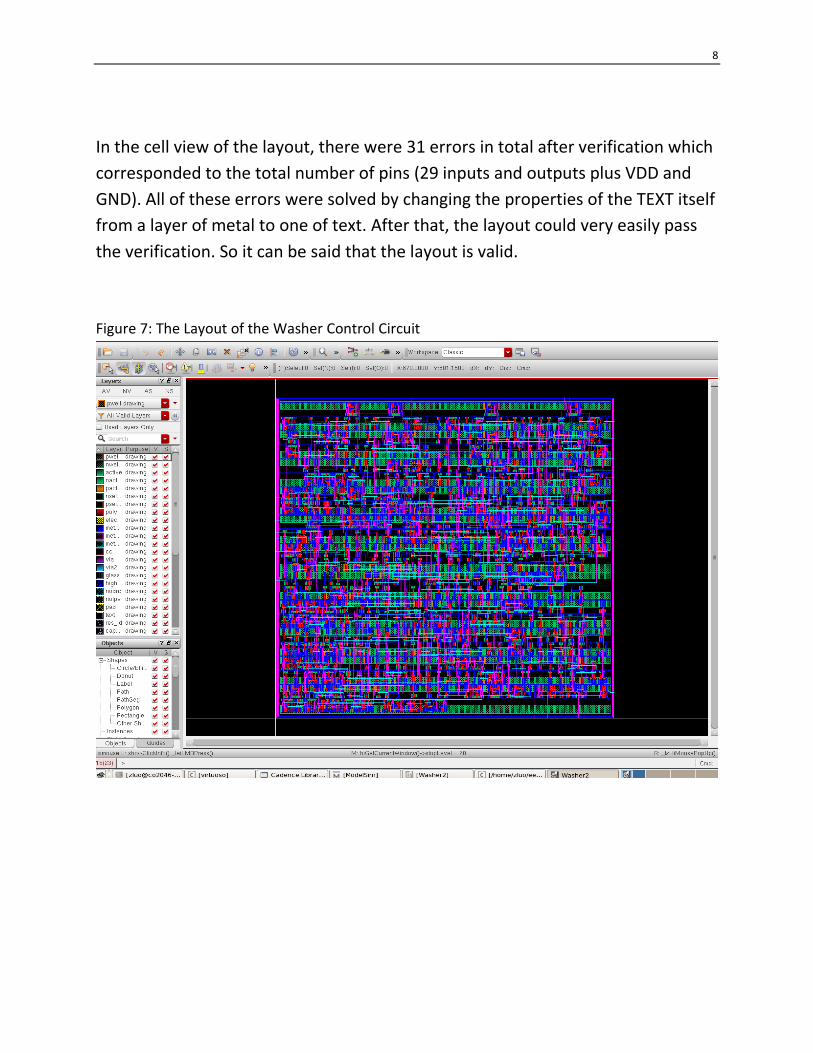
In the cell view of the layout, there were 31 errors in total after verification which
corresponded to the total number of pins (29 inputs and outputs plus VDD and
GND). All of these errors were solved by changing the properties of the TEXT itself
from a layer of metal to one of text. After that, the layout could very easily pass
the verification. So it can be said that the layout is valid.
Figure 7: The Layout of the Washer Control Circuit

9
Figure 8: The Layout Passed DRC
10
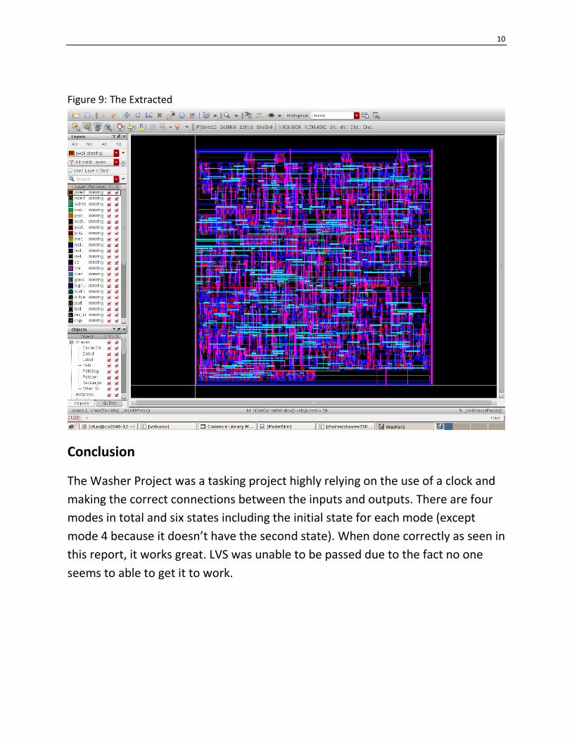
Figure 9: The Extracted
Conclusion
The Washer Project was a tasking project highly relying on the use of a clock and
making the correct connections between the inputs and outputs. There are four
modes in total and six states including the initial state for each mode (except
mode 4 because it doesn’t have the second state). When done correctly as seen in
this report, it works great. LVS was unable to be passed due to the fact no one
seems to able to get it to work.

11
Appendix 1: Verilog Code
module Washer2(start,m1,m2,m3,m4,p,clk,redled,mled,buzzer,fill,spin,control,display);
input start,m1,m2,m3,m4,p,clk;
wire start,m1,m2,m3,m4,p,clk;
output reg redled,buzzer,fill,spin;
output reg [3:0] mled;
output reg [3:0] control;
output reg [9:0] display;
reg [7:0] state;
reg [7:0] next_state;
reg [7:0] temp;
reg [3:0] dis1;
reg [3:0] dis2;
reg [3:0] dis3;
reg flag;
reg stop;
reg stop2;
reg reset;
reg reset2;
reg [3:0] count2;
reg [12:0] count;
reg [3:0] count3;
reg [3:0] count4;
parameter
s0=8'b00000000, s1=8'b00010000, s2=8'b00001000,
s3=8'b00000100, s4=8'b00000010, s5=8'b00000001;
always @(posedge clk)begin
if(start==0)
begin
state=s0;
buzzer=0;
redled=1;
stop=0;
fill=0;
spin=0;
reset=1;
reset2=1;
count3=0;
count4=0;
12
stop2=1;
if(m1) mled=4'b1110;
if(m2) mled=4'b1101;
if(m3) mled=4'b1011;
if(m4) mled=4'b0111;
end
if(reset==1)count<=13'd0;
if(reset==0)count<=count+1;
if(reset2==1)count2<=4'd0;
if(reset2==0)count2<=count2+1;
case(mled)
4'b1110:
begin
if(start==1)
begin
if(p==1)
begin
redled=0;
case(state)
s0:if(stop==0) begin flag=1;reset=0;end
s1:begin if(count==180)begin reset=1;flag=1;end if(flag==0)reset=0;end
s2:begin if(count==600)begin reset=1;flag=1;end if(flag==0)reset=0;end
s3:begin if(count==720)begin reset=1;flag=1;end if(flag==0)reset=0;end
s4:begin if(count==2880)begin reset=1;flag=1;end if(flag==0)reset=0;end
s5:begin if(count==600)begin reset=1;flag=1;stop=1;end if(flag==0)reset=0;end
endcase
if(flag==1&&count==0)
begin
state=next_state;
if(count==0)flag=0;
if(state==s0)begin fill=0;spin=0;end
if(state==s1)begin dis1=0;dis2=3;dis3=0;fill=1;spin=0;end
if(state==s2)begin dis1=1;dis2=0;dis3=0;fill=0;spin=0;end
if(state==s3)begin dis1=1;dis2=2;dis3=0;fill=0;spin=0;end
if(state==s4)begin dis1=4;dis2=8;dis3=0;fill=0;spin=0;end
if(state==s5)begin dis1=1;dis2=0;dis3=0;fill=0;spin=1;end
temp=(8'b10000000) | state;
end

13
end
end
end
4'b1101:
begin
if(start==1)
begin
if(p==1)
begin
redled=0;
case(state)
s0:if(stop==0) begin flag=1;reset=0;end
s1:begin if(count==180)begin reset=1;flag=1;end if(flag==0)reset=0;end
s2:begin if(count==900)begin reset=1;flag=1;end if(flag==0)reset=0;end
s3:begin if(count==540)begin reset=1;flag=1;end if(flag==0)reset=0;end
s4:begin if(count==1680)begin reset=1;flag=1;end if(flag==0)reset=0;end
s5:begin if(count==600)begin reset=1;flag=1;stop=1;end if(flag==0)reset=0;end
endcase
if(flag==1&&count==0)
begin
state=next_state;
if(count==0)flag=0;
if(state==s0)begin fill=0;spin=0;end
if(state==s1)begin dis1=0;dis2=3;dis3=0;fill=1;spin=0;end
if(state==s2)begin dis1=1;dis2=5;dis3=0;fill=0;spin=0;end
if(state==s3)begin dis1=0;dis2=9;dis3=0;fill=0;spin=0;end
if(state==s4)begin dis1=2;dis2=8;dis3=0;fill=0;spin=0;end
if(state==s5)begin dis1=1;dis2=0;dis3=0;fill=0;spin=1;end
temp=(8'b01000000) | state;
end
end
end
end
4'b1011:
begin
if(start==1)
begin
if(p==1)
begin
14
redled=0;
case(state)
s0:if(stop==0) begin flag=1;reset=0;end
s1:begin if(count==180)begin reset=1;flag=1;end if(flag==0)reset=0;end
s2:begin if(count==600)begin reset=1;flag=1;end if(flag==0)reset=0;end
s3:begin if(count==1200)begin reset=1;flag=1;end if(flag==0)reset=0;end
s4:begin if(count==5400)begin reset=1;flag=1;end if(flag==0)reset=0;end
s5:begin if(count==600)begin reset=1;flag=1;stop=1;end if(flag==0)reset=0;end
endcase
if(flag==1&&count==0)
begin
state=next_state;
flag=0;
if(state==s0)begin fill=0;spin=0;end
if(state==s1)begin dis1=0;dis2=3;dis3=0;fill=1;spin=0;end
if(state==s2)begin dis1=2;dis2=0;dis3=0;fill=0;spin=0;end
if(state==s3)begin dis1=1;dis2=2;dis3=0;fill=0;spin=0;end
if(state==s4)begin dis1=9;dis2=0;dis3=0;fill=0;spin=0;end
if(state==s5)begin dis1=1;dis2=0;dis3=0;fill=0;spin=1;end
temp=(8'b00100000) | state;
end
end
end
end
4'b0111:
begin
if(start==1)
begin
if(p==1)
begin
redled=0;
case(state)
s0:if(stop==0) begin flag=1;reset=0;end
s1:begin if(count==180)begin reset=1;flag=1;end if(flag==0)reset=0;end
s2:begin if(count==0)begin reset=1;flag=1;end if(flag==0)reset=0;end
s3:begin if(count==360)begin reset=1;flag=1;end if(flag==0)reset=0;end
s4:begin if(count==480)begin reset=1;flag=1;end if(flag==0)reset=0;end
s5:begin if(count==600) begin reset=1;flag=1;stop=1;end if(flag==0)reset=0;end
endcase

15
if(flag==1&&count==0)
begin
state=next_state;
flag=0;
if(state==s0)begin fill=0;spin=0;end
if(state==s1)begin dis1=0;dis2=3;dis3=0;fill=1;spin=0;end
if(state==s2)begin dis1=0;dis2=0;dis3=0;fill=0;spin=0;end
if(state==s3)begin dis1=0;dis2=6;dis3=0;fill=0;spin=0;end
if(state==s4)begin dis1=0;dis2=8;dis3=0;fill=0;spin=0;end
if(state==s5)begin dis1=1;dis2=0;dis3=0;fill=0;spin=1;end
temp=(8'b01000000) | state;
end
end
end
end
endcase
if(stop2==1&&stop==1)begin
if(count2!=15)begin reset2=0;buzzer=1;end
if(count2==15)
begin
stop2=0;
reset2=1;
buzzer=0;
end
end
if(dis3==0&&dis2>0)
begin
if(count3!=6)count3=count3+1;
if(count3==6)begin
dis2=dis2-1;
dis3=9;
count3=0;
end
end
if(dis2==0&&dis3==0&&dis1>0)
begin
if(count3!=6)count3=count3+1;
if(count3==6)begin
dis1=dis1-1;
dis2=9;

16
dis3=9;
count3=0;
end
end
if(dis3>0)
begin
if(count4!=6)count4=count4+1;
if(count4==6)
begin
dis3=dis3-1;
count4=0;
end
end
if(dis3>0)
begin
case(dis3)
4'd0:display=10'b0011111110;
4'd1:display=10'b0010110000;
4'd2:display=10'b0011101101;
4'd3:display=10'b0011111001;
4'd4:display=10'b0010110011;
4'd5:display=10'b0011011011;
4'd6:display=10'b0011011111;
4'd7:display=10'b0011110000;
4'd8:display=10'b0011111111;
4'd9:display=10'b0011111011;
endcase
end
if(dis3==0&&dis2>0)
begin
case(dis2)
4'd0:display=10'b0101111110;
4'd1:display=10'b0100110000;
4'd2:display=10'b0101101101;
4'd3:display=10'b0101111001;
4'd4:display=10'b0100110011;
4'd5:display=10'b0101011011;
4'd6:display=10'b0101011111;
4'd7:display=10'b0101110000;
4'd8:display=10'b0101111111;

17
4'd9:display=10'b0101111011;
endcase
end
if(dis3==0&&dis2==0)
begin
case(dis1)
4'd0:display=10'b1001111110;
4'd1:display=10'b1000110000;
4'd2:display=10'b1001101101;
4'd3:display=10'b1001111001;
4'd4:display=10'b1000110011;
4'd5:display=10'b1001011011;
4'd6:display=10'b1001011111;
4'd7:display=10'b1001110000;
4'd8:display=10'b1001111111;
4'd9:display=10'b1001111011;
endcase
end
end
always @ (state)
begin
case(state)
s0: next_state=s1;
s1: next_state=s2;
s2: next_state=s3;
s3: next_state=s4;
s4: next_state=s5;
s5: next_state=s0;
endcase
end
always @ (temp) begin
case(temp)
8'b10010000:control=4'd0;
8'b10001000:control=4'd1;
8'b10000100:control=4'd2;
8'b10000010:control=4'd3;
8'b10000001:control=4'd4;
8'b01010000:control=4'd5;
8'b01001000:control=4'd6;
8'b01000100:control=4'd7;

18
8'b01000010:control=4'd8;
8'b01000001:control=4'd9;
8'b00110000:control=4'd10;
8'b00101000:control=4'd11;
8'b00100100:control=4'd12;
8'b00100010:control=4'd13;
8'b00100001:control=4'd14;
8'b10000000:control=4'd15;
8'b01000000:control=4'd15;
8'b00100000:control=4'd15;
endcase
end
endmodule
19
Appendix 2: Verilog Test Bench
`timescale 1s/1ms
module washer_tb();
reg start,m1,m2,m3,m4,p,clk;
wire redled,buzzer,fill,spin;
wire [3:0] mled;
wire [3:0] control;
wire [9:0] display;
Washer2
washer_m1(.start(start),.m1(m1),.m2(m2),.m3(m3),.m4(m4),.p(p),.clk(clk),.redled(redled),.mled(mled),.
buzzer(buzzer),.fill(fill),.spin(spin),.control(control),.display(display));
initial
begin
clk=1'b0;
start=1'b0;
m1=1'b0;
m2=1'b0;
m3=1'b0;
m4=1'b0;
p=1'b1;
#10 m1=1'b1; //By changing m1 to m2, m3, or m4, this code can test mode 2, mode 3, or mode 4.
#25 start=1'b1;
#50 p=1'b0;
#60 p=1'b1;
end
always
begin
#1 clk=~clk;
end
endmodule