ee201 fundamentals of electric circuits by dr. ibraheem nasiruddin 1 wheel-3:
TRANSCRIPT

EE201 Fundamentals of Electric Circuits
by
Dr. Ibraheem Nasiruddin
1
WHEEL-3:

Connect / Attend
Connect: Create an opposite experience
Asking students to hold any items with their hands and touch other students at hand, shoulder, legs in random manner
Attend:
• Listen individual Responses
• Seek their way to do the same process
2
conclude connect and attend activity and compile thoughts conclude connect and attend activity and compile thoughts Ask them to list down their observation based on the experinceAsk them to list down their observation based on the experince List down process of analysis List down process of analysis

Image

DC CIRCUIT ANALYSIS AND NETWORK THEOREMS
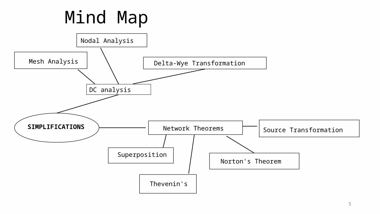
Mind Map
5
TASIMPLIFICATIONS
DC analysis
Network Theorems
Superposition
Thevenin's
Norton's Theorem
Source Transformation
Mesh Analysis Delta-Wye Transformation
Nodal Analysis
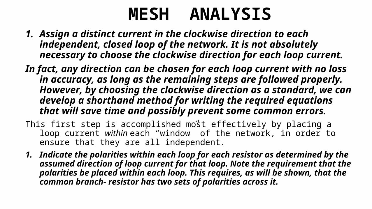
MESH ANALYSIS1. Assign a distinct current in the clockwise direction to each
independent, closed loop of the network. It is not absolutely necessary to choose the clockwise direction for each loop current.
In fact, any direction can be chosen for each loop current with no loss in accuracy, as long as the remaining steps are followed properly. However, by choosing the clockwise direction as a standard, we can develop a shorthand method for writing the required equations that will save time and possibly prevent some common errors.
This first step is accomplished most effectively by placing a loop current within each “window” of the network, in order to ensure that they are all independent.
1. Indicate the polarities within each loop for each resistor as determined by the assumed direction of loop current for that loop. Note the requirement that the polarities be placed within each loop. This requires, as will be shown, that the common branch- resistor has two sets of polarities across it.

3. Apply Kirchhoff’s voltage law around each closed loop in the clockwise direction. Again, the clockwise direction was chosen to establish uniformity and prepare us for the method to be introduced later.a) If a resistor has two or more assumed currents through it, the total current
through the resistor is the assumed current of the loop in which Kirchhoff’s voltage law is being applied, plus the assumed currents of the other loops passing through in the same direction, minus the assumed currents through in the opposite direction.
b) The polarity of a voltage source is unaffected by the direction of the assigned loop currents.
4. Solve the resulting simultaneous linear equations for the assumed loop currents.

Example

Example

Example

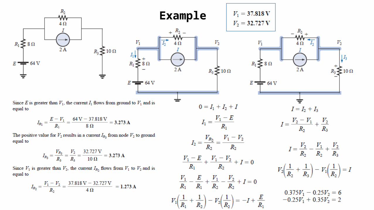
MESH ANALYSIS with Current SourcesOn occasion there will be current sources in the network to which mesh analysis
is to be applied. In such cases one can convert the current source to a voltage source (if a parallel resistor is present) and proceed as before, or use the following technique:
•Assign a mesh current to each independent loop, including the current sources. •Redraw the network if necessary by removing the current sources (replace with open-circuit). •Apply Kirchhoff’s voltage law to all the remaining independent paths of the network. Note that the mesh currents I1 – I2 = I = 4 A.
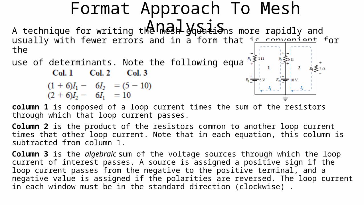
Format Approach To Mesh AnalysisA technique for writing the mesh equations more rapidly and usually with
fewer errors and in a form that is convenient for the use of determinants. Note the following equations:
column 1 is composed of a loop current times the sum of the resistors through which that loop current passes. Column 2 is the product of the resistors common to another loop current times that other loop current. Note that in each equation, this column is subtracted from column 1. Column 3 is the algebraic sum of the voltage sources through which the loop current of interest passes. A source is assigned a positive sign if the loop current passes from the negative to the positive terminal, and a negative value is assigned if the polarities are reversed. The loop current in each window must be in the standard direction (clockwise) .

Example

NODAL ANALYSIS• In loop analysis, the general network equations were obtained by
applying Kirchhoff’s voltage law around each closed loop. • Now Kirchhoff’s current law is used to develop a method referred to as
nodal analysis.• A node is defined as a junction of two or more branches. Define one
node as a reference (that is, a point of zero potential or ground), the remaining nodes of the network will all have a fixed potential relative to this reference.
• For a network of N nodes, there will exist (N - 1) nodes with a fixed potential relative to the assigned reference node. Equations relating these nodal voltages can be written by applying Kirchhoff’s current law at each node.
• Solve these nodal voltages in the same manner in which loop currents were found in loop analysis.


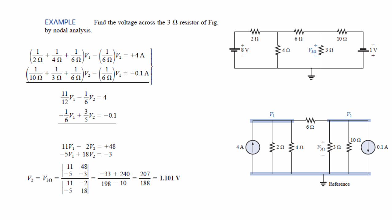
Example
Steps 1 and 2: The network has two nodes, as shown in the above Fig. The lower node is defined as the reference node at ground potential (zero volts), and the other node as V1, the voltage from node 1 to ground.Step 3: I1 and I2 are defined as leaving the node in the Fig., and Kirchhoff’s current law is applied as follows:
Example

Nodal ANALYSIS with Voltage SourcesOn occasion there will be voltage sources in the network to which nodal
analysis is to be applied. In such cases one can convert the voltage source to a current source (if a series resistor is present) and proceed as before, or use the following technique:•Start as before and assign a nodal voltage to each independent node of the network •Redraw the network if necessary by removing the voltage sources (replace with short-circuit). •Apply Kirchhoff’s current law to all the remaining independent nodes of the network. •Finally, relate the defined nodes to the independent voltage sources of the network, and solve for the nodal voltages.

Example
In particular, note that the current I3 will leave the supernode atV1 and then enter the same supernode at V2. It must therefore appear twice when applying Kirchhoff’s current law, as shown:
Note that, before any analysis, the voltage across the resistor R3 must be12 V and I3 must be equal to 1.2 A.

Format Approach To Nodal Analysis
• A technique for writing the nodal equations more rapidly and usually with fewer errors and in a form that is convenient for the use of determinants.
• the subscripted voltage at the node in which Kirchhoff’s current law is applied is multiplied by the sum of the conductances attached to that node. Note also that the other nodal voltages within the same equation are multiplied by the negative of the conductance between the two nodes.
• The current sources are represented to the right of the equals sign with a positive sign if they supply current to the node and with a negative sign if they draw current from the node.
• A major requirement, however, is that all voltage sources must first be converted to current sources before the procedure is applied.

Example


Example
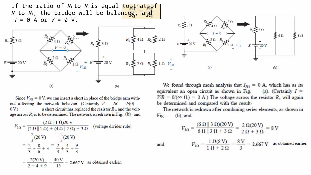
If the ratio of R1 to R3 is equal to that ofR2 to R4, the bridge will be balanced, and I = 0 A or V = 0 V.

Home Assignment-6
27
Solve Examples from each section
Submit solution of selected question

QUIZ-6
28

Circuit configurations are often encountered in which the resistors do not appear to be in series or parallel. Under these conditions, it may be necessary to convert the circuit from one form to another to solve for any unknown quantities if mesh or nodal analysis is not applied.
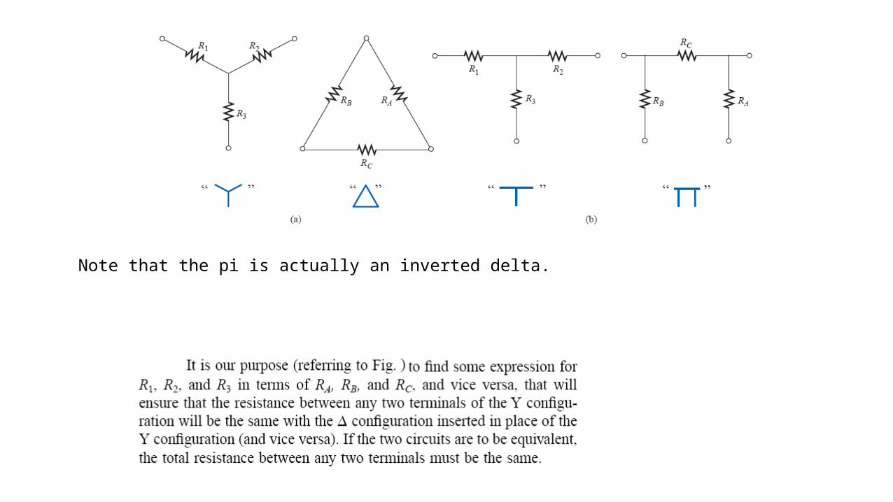
Note that the pi is actually an inverted delta.


Home Assignment-7
36
Solve Examples from each section
Submit solution of selected question

QUIZ-7
37
Network Theorems
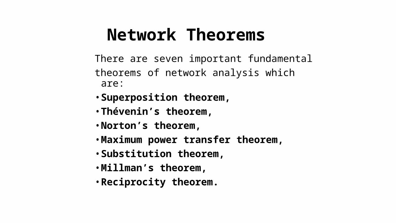
There are seven important fundamental theorems of network analysis which are: • Superposition theorem, • Thévenin’s theorem, • Norton’s theorem,• Maximum power transfer theorem,• Substitution theorem,• Millman’s theorem,• Reciprocity theorem.

Superposition theorem
It can be used to find the solution to networks with two or more sources that are not in series or parallel.
The current through, or voltage across, an element in a linear bilateral network is equal to the algebraic sum of the currents or voltages produced independently by each source.
To consider the effects of each source independently requires that all other sources be removed and replaced without affecting the final result. The total current through any portion of the network is equal to the algebraic sum of the currents produced independently by each source.

To remove a voltage source when applying this theorem, the difference in potential between the terminals of the voltage source must be set to zero(short circuit); removing a current source requires that its terminals be opened (open circuit). Any internal resistance or conductance associatedwith the displaced sources is not eliminated but must still be considered.

The superposition principle is not applicable to power
effects since the power loss in a resistor varies as the square
(nonlinear) of the current or voltage.
The total power delivered to a resistive element must be
determined using the total current through or the total
voltage across the element and cannot be determined by a
simple sum of the power levels established by each source.
if
but


Thévenin’s theoremAny two-terminal, linear bilateral dc network can be
replaced by an equivalent circuit consisting of a
voltage source and a series resistor, as shown
The Thévenin equivalent circuit provides an equivalence at theterminals only—the internal construction and characteristics of the original network and the Thévenin equivalent are usually quite different.


NORTON’S THEOREMAny two-terminal linear bilateral dc network can be replaced by an equivalent circuit consisting of a current source and a parallel resistor.It was demonstrated before that every voltage source with a series internal resistance has a current source equivalent. The current source equivalent of the Thévenin network can be determined by Norton’s theorem as shown in Fig.


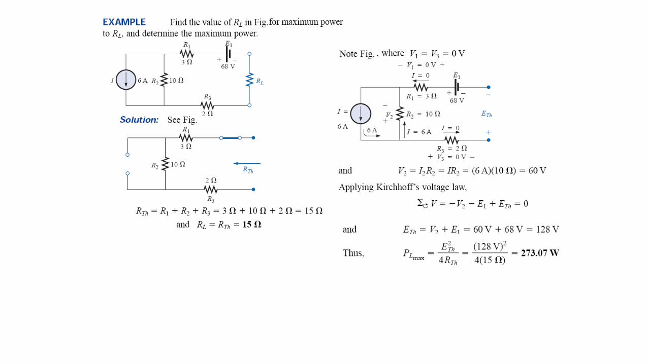
MAXIMUM POWER TRANSFER THEOREM
A load will receive maximum power from a linear
bilateral dc network when its total resistive value
is exactly equal to the Thévenin resistance of the
network as “seen” by the load.
For the Thévenin equivalent circuit, maximum power will be delivered to the load when RL = R TH
For the Norton equivalent circuit, maximum power will be delivered to the load when RL = RN


Note that a small change in load resistance for levels of RL below RTh will have a moredramatic effect on the power delivered than similar changes in RL above the RTh level.

Note again that the most dramatic changes in VL and IL occur for levels of RL less than RTh. As pointed out on the plot, when RL= RTh, VL = ETh/2 and IL = Imax/2, with Imax = ETh/RTh.

DC Operating EfficiencyThe dc operating efficiency of a system is defined by the
ratio of the power delivered to the load to the power
supplied by the source; that is,
The efficiency therefore increases linearly and dramatically for small levels of RL and then begins to level off as it approaches the 100% level for very large values of RL, as shown in Fig. However, the efficiency criterion is sensitive only to the ratio of PL to Ps and not to their actual levels. At efficiency levels approaching 100%, the power delivered to the load may be so small as to have little practical value. Note that at RL = 1000Ω , PL = 3.54 Watt and while at max. PL = 100W
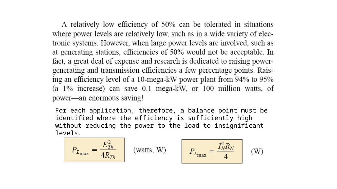
For each application, therefore, a balance point must be identified where the efficiency is sufficiently high without reducing the power to the load to insignificant levels.

This Figure is a semi log plot of
PL and the power delivered by the
source Ps = EThIL versus RL for
ETh = 60 V and RTh = 9 Ω.
It is now quite clear that the PL
curve has only one maximum
(at RL = RTh), whereas Ps
decreases for every increase in RL


MILLMAN’S THEOREM
Through the application of Millman’s theorem, any number of parallel voltage sources can be reduced to one.

Example

Steps followed to apply Millman’s Theorm
Step 1: Convert all voltage sources to current sources.

Where


The dual of Millman’s theorem

SUBSTITUTION THEOREM
a known potential difference and current in a network can be replaced by an ideal voltage source and current source, respectively. This theorem cannot be used to solve networks with two or more sources that are not in series or parallel.


RECIPROCITY THEOREM

Example


Home Assignment-8
81
Solve Examples from each section
Submit solution of selected question

QUIZ-8
82

Report-2
83
•create a chart/presentation on the process/product which demonstrates the concept in real life