ee141 © digital integrated circuits 2nd introduction 1 ee5900 robust vlsi computer-aided design dr....
TRANSCRIPT

EE141© Digital Integrated Circuits2nd Introduction1
EE5900 Robust VLSI EE5900 Robust VLSI Computer-Aided Computer-Aided DesignDesign
Dr. Shiyan HuOffice: EERC [email protected]
Adapted and modified from Digital Integrated Circuits: A Design Perspective by Jan M. Rabaey, Anantha Chandrakasan, and Borivoje Nikolic.
IntroductionIntroduction

EE141© Digital Integrated Circuits2nd Introduction
Class Time and Office HourClass Time and Office Hour Class Time: MWF 14:05-14:55 (EERC 216) Office Hours: MWF 15:00-15:50 or by appointment, office:
EERC 731 Textbook (suggested)
Handbook of Algorithms for Physical Design Automation, Charles J. Alpert, Dinesh P. Mehta, Sachin S. Sapatnekar, CRC Press, 2008
Grading: Homework 25% Project 25% Exams 50%
2

EE141© Digital Integrated Circuits2nd Introduction
Course WebsiteCourse Website http://www.ece.mtu.edu/faculty/shiyan/EE5900Spring11.htm Contact information of instructor
Email: [email protected] EERC 731 Instructor’s webpage: http://www.ece.mtu.edu/faculty/shiyan
3

EE141© Digital Integrated Circuits2nd Introduction4
IntroductionIntroduction
Why is designing digital ICs different today than it was before?
What is the challenge?

EE141© Digital Integrated Circuits2nd Introduction
The Transistor Revolution
First transistorBell Labs, 1948

EE141© Digital Integrated Circuits2nd Introduction
The First Integrated Circuit
First ICJack KilbyTexas Instruments1958

EE141© Digital Integrated Circuits2nd Introduction7
Intel 4004 Micro-ProcessorIntel 4004 Micro-Processor
19711000 transistors1 MHz operation

EE141© Digital Integrated Circuits2nd Introduction
Intel 8080 Micro-Processor
19744500 transistors

EE141© Digital Integrated Circuits2nd Introduction9
Intel Pentium (IV) microprocessor
200042 million transistors1.5 GHz

EE141© Digital Integrated Circuits2nd Introduction10
Not Only MicroprocessorsNot Only Microprocessors
Digital Cellular Market(Phones Shipped)
1996 1997 1998 1999 2000
Units 48M 86M 162M 260M 435M Analog Baseband
Digital Baseband
(DSP + MCU)
PowerManagement
Small Signal RF
PowerRF
((data from Texas Instruments)data from Texas Instruments)
CellPhone

EE141© Digital Integrated Circuits2nd Introduction11
Many Chips

EE141© Digital Integrated Circuits2nd Introduction12
Basic Components In VLSI CircuitsBasic Components In VLSI Circuits
Devices Transistors Logic gates and cells Function blocks
Interconnects Local interconnects Global interconnects Clock interconnects Power/ground nets

EE141© Digital Integrated Circuits2nd Introduction13
Cross-Section of A ChipCross-Section of A Chip

EE141© Digital Integrated Circuits2nd Introduction
CMOS transistorsCMOS transistors3 terminals in CMOS transistors: G: Gate D: Drain S: Source
nMOS transistor/switch X=1 switch closes (ON) X=0 switch opens (OFF)
pMOS transistor/switch X=1 switch opens (OFF) X=0 switch closes (ON)

EE141© Digital Integrated Circuits2nd Introduction
An Example: CMOS InverterAn Example: CMOS Inverter
X F = X’X’
Logic symbol
X F = X’X’
+Vdd
GRD
Transistor-level schematicOperation: X=1 nMOS switch conducts (pMOS is open) and draws from GRD F=0 X=0 pMOS switch conducts (nMOST is open) and draws from +Vdd F=1

EE141© Digital Integrated Circuits2nd Introduction16
Moore’s LawMoore’s Law
In 1965, Gordon Moore noted that the number of transistors on a chip doubled every 18 to 24 months. He made a prediction that semiconductor technology will double its effectiveness every 18 monthsNot true any more
Interconnect delay dominatesVariations

EE141© Digital Integrated Circuits2nd Introduction17
Moore’s LawMoore’s Law
161514131211109876543210
195
9
196
0
196
1
196
2
196
3
196
4
196
5
196
6
196
7
196
8
196
9
197
0
197
1
197
2
197
3
197
4
197
5
LO
G 2 O
F T
HE
NU
MB
ER
OF
CO
MP
ON
EN
TS
PE
R I
NT
EG
RA
TE
D F
UN
CT
ION
Electronics, April 19, 1965.
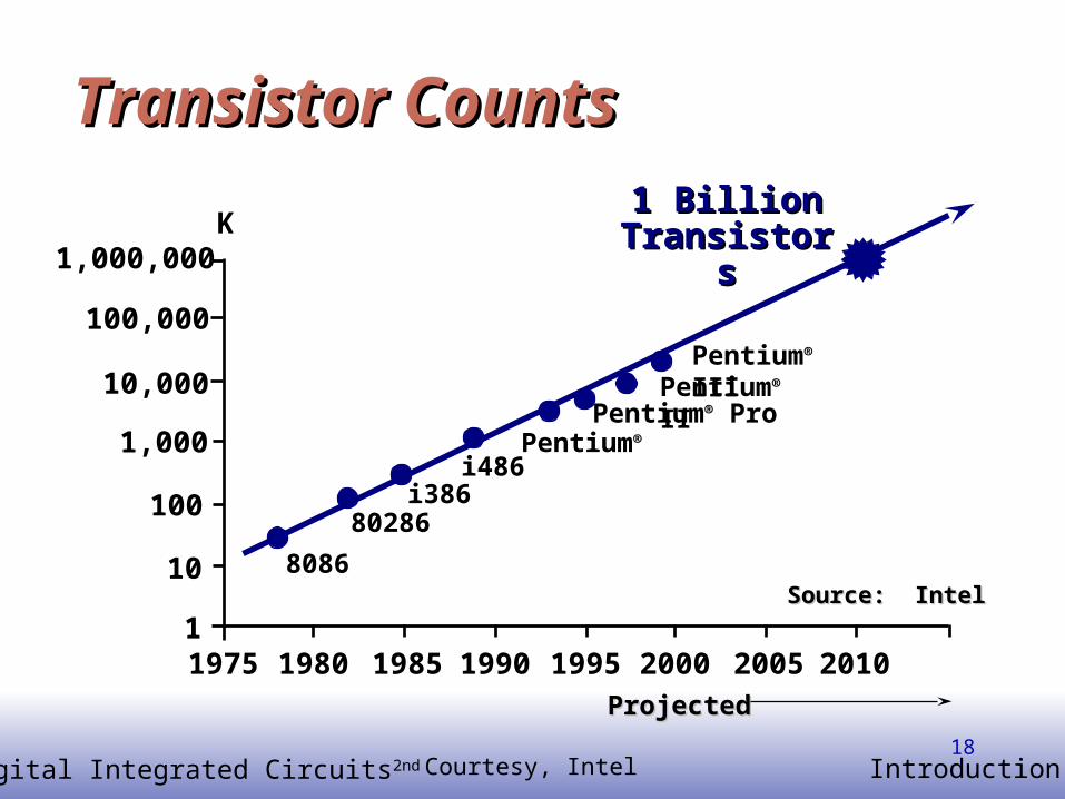
EE141© Digital Integrated Circuits2nd Introduction18
Transistor CountsTransistor Counts
1,000,000
100,000
10,000
1,000
10
100
11975 1980 1985 1990 1995 2000 2005 2010
8086
80286i386
i486Pentium®
Pentium® Pro
K1 1 Billion Billion
TransistorsTransistors
Source: IntelSource: Intel
ProjectedProjected
Pentium® IIPentium® III
Courtesy, Intel

EE141© Digital Integrated Circuits2nd Introduction19
Moore’s law in MicroprocessorsMoore’s law in Microprocessors
40048008
80808085 8086
286386
486Pentium® proc
P6
0.001
0.01
0.1
1
10
100
1000
1970 1980 1990 2000 2010Year
Tra
nsi
sto
rs (
MT
)
2X growth in 1.96 years!
Transistors on Lead Microprocessors double every 2 yearsTransistors on Lead Microprocessors double every 2 years
Courtesy, Intel

EE141© Digital Integrated Circuits2nd Introduction20
ITRS Prediction

EE141© Digital Integrated Circuits2nd Introduction21
Power DissipationPower Dissipation
P6Pentium ® proc
486
3862868086
80858080
80084004
0.1
1
10
100
1971 1974 1978 1985 1992 2000Year
Po
wer
(W
atts
)
Lead Microprocessors power continues to increaseLead Microprocessors power continues to increase
Courtesy, Intel

EE141© Digital Integrated Circuits2nd Introduction22
Power is a major problemPower is a major problem
5KW 18KW
1.5KW 500W
40048008
80808085
8086286
386486
Pentium® proc
0.1
1
10
100
1000
10000
100000
1971 1974 1978 1985 1992 2000 2004 2008Year
Po
wer
(W
atts
)
Power delivery and dissipation will be prohibitivePower delivery and dissipation will be prohibitive
Courtesy, Intel

EE141© Digital Integrated Circuits2nd Introduction23
Power densityPower density
400480088080
8085
8086
286386
486Pentium® proc
P6
1
10
100
1000
10000
1970 1980 1990 2000 2010Year
Po
wer
Den
sity
(W
/cm
2)
Hot Plate
NuclearReactor
RocketNozzle
Power density too high to keep junctions at low tempPower density too high to keep junctions at low temp
Courtesy, Intel

EE141© Digital Integrated Circuits2nd Introduction24
System Specification
Functional Design
Logic Design and Synthesis
e.g., Verilog
X=(AB*CD)+(A+D)+(A(B+C))
Y=(A(B+C))+AC+D+A(BC+D))
VLSI Design CycleVLSI Design Cycle

EE141© Digital Integrated Circuits2nd Introduction25
Physical Design
Fabrication
Packaging
VLSI Design Cycle (cont.)VLSI Design Cycle (cont.)

EE141© Digital Integrated Circuits2nd Introduction26
0.18
Source: Gordon Moore, Chairman Emeritus, Intel Corp.
0
50
100
150
200
250
300
Technology generation (m)
Del
ay (
pse
c)
Transistor/Gate delay
Interconnect delay
0.8 0.5 0.250.25
0.150.35
Interconnects Dominate Interconnects Dominate

EE141© Digital Integrated Circuits2nd Introduction27
Transistors/Cells
Interconnection
Interconnection
Transistors/Cells
Conventional Approach New Approach
Interconnect-Driven Design
New Paradigm for VLSI DesignNew Paradigm for VLSI Design

EE141© Digital Integrated Circuits2nd Introduction28
Given a circuit after logic synthesis, to convert it into a layout (i.e., determine the physical location of each gate and the interconnects between gates).
Physical DesignPhysical Design
PD

EE141© Digital Integrated Circuits2nd Introduction29
Nanoscale ChallengesNanoscale Challenges Interconnect-limited designs
Interconnect performance limitation Interconnect modeling complexity Interconnect reliability (signal integrity)
Power barrier High degree of on-chip integration
Complexity and productivity System on a chip
Variations

EE141© Digital Integrated Circuits2nd Introduction30
Robust Design For VariationsRobust Design For Variations
Variations The difference between the designed value and the actual
value Robust design
Mitigate or compensate for variations Robustness for lithography-induced variations

EE141© Digital Integrated Circuits2nd Introduction3131
Chip Design and FabricationChip Design and Fabrication
Lithography Process
Designed Chip Layout
Fabricated Chip

EE141© Digital Integrated Circuits2nd Introduction3232
Photo-Lithography ProcessPhoto-Lithography Process
oxidation
opticalmask
processstep
photoresist coatingphotoresistremoval (ashing)
spin, rinse, dryacid etch
photoresist
stepper exposure
development
Typical operations in a single photolithographic cycle (from [Fullman]).

EE141© Digital Integrated Circuits2nd Introduction3333
Lithography SystemLithography System
Illumination
Mask
Objective Lens
Aperture
Wafer
193nm wavelength
45nm features

EE141© Digital Integrated Circuits2nd Introduction3434
Mask v.s. PrintingMask v.s. Printing0.25µ 0.18µ
0.13µ 90-nm 65-nm
Layout
What you design is NOT what you get!

EE141© Digital Integrated Circuits2nd Introduction3535
MotivationMotivation Chip design cannot be fabricated
Gap– Lithography technology: 193nm wavelength – VLSI technology: 45nm features
Lithography induced variations– Impact on timing and power
Even for 180nm technology, variations up to 20x in leakage power and 30% in frequency were reported.
Technology nodeTechnology node 130nm130nm 90nm90nm 65nm65nm 45n45nmm
Gate length (nm)Gate length (nm)Tolerable variation Tolerable variation
(nm)(nm)
90905.35.3
53533.753.75
35352.52.5
282822
Wavelength (nm)Wavelength (nm) 248248 193193 193193 193193

EE141© Digital Integrated Circuits2nd Introduction3636
Gap: Lithography Tech. v.s. VLSI Tech.Gap: Lithography Tech. v.s. VLSI Tech.
193nm 28nm, tolerable distortion: 2nm
Increasing gap Printability problem (and
thus variations) more severe!

EE141© Digital Integrated Circuits2nd Introduction37
SummarySummary Digital integrated circuit design challenges in
nanoscale regime High speed Low power Short design time for highly complex circuit having
over 1 billion transistors Reliable under variations