ee design guide - rochester institute of technologyedge.rit.edu/content/p15201/public/msd...
TRANSCRIPT

2015
EE Design Guide
Version 1.3Jordan Skiff, Ben HaaG, Vincent Pan

Project P15201 Tigerbot
Table of Contents
Proposed Bill of Materials (BOM).......................................................2)System Overview ......................................................………………..3)
Subsystem Overview 1.Subsystem Overview 2...........................................................4)
Schematic System Overview .............................................................5)Breakdown of Body Area’s.................................................................5)
Ankle.......................................................................................6)Hip/Knee.................................................................................7)
Torso.......................................................................................8)Misc. (Power, Ground, Computing).........................................9)Highlights and Concerns........................................................10)
Schematic Subsystems.....................................................................11)Microcontroller
Teensy 3.1 Documentation.........................................12)ADC Board.............................................................................14)
ADC128D818 Datasheet............................................15)Force Sensing Resistor Board...............................................18)
FSR A201 Datasheet..................................................19)TL074A Datasheet......................................................20)
Sensor Overview ...............................................................................22)Sensor Highlights
Sharp IR GP2Y0A21YK0FParallax Ping)))
Wiring Diagram.......................................................................23)PCB Layout.........................................................................................24)
ADC BoardFSR Board………………………………………………………..25)Distribution Board (TBD)
Power Systems Information...............................................................26)Battery and Battery Related Fixed Supply...........................................................................29)Regulation
Testing………………..........................................................................32)Scheduling………………………………………………………………...35)Update……………………………………………………………………..36)
1

Project P15201 Tigerbot
Proposed BOM:
We are using 0.805 Imperial for Surface mount discrete components. Because the IC’s we have selected are surface mount and this is the smallest size available in PCB Artist and we wanted to make all components have a uniform standard.
2

Project P15201 Tigerbot
System Overview:
Subsystem Overview:
3

Project P15201 Tigerbot
Subsystem Overview 2
4

Project P15201 Tigerbot
Insert Schematic Page 1
5

Project P15201 Tigerbot
Breakdown of Body Areas:
Ankle:
6

Project P15201 Tigerbot
Hip/Knee:
7

Project P15201 Tigerbot
Upper Body: Torso, Arms, Shoulders, Elbows
8

Project P15201 Tigerbot
Misc: Power, Ground Computing:
9

Project P15201 Tigerbot
Highlights and Concerns:
To simplify the operation of Tigerbot, the Robotic Operating System or ROS has been selected as the key software for operations. The Pandaboard has been selected as the primary computing hardware, for now due to the amount of support available and compatibility with ROS. However due to the amount of processing required, control of the servo motors has been distributed to a network of Teensy 3.1 microcontrollers. Teensy 3.1 has a 32 bit processor, compatibility with ROS, and onboard micro-usb support. Combined with the use of a seven port USB hub the microcontroller network can process raw data and transport it to the main board with USB speed without slowing down the main cpu. The drawback of the Teensy 3.1 is that it only has 2 channels for ADC, even with 20 Analog inputs. To accommodate this, a simplified ADC board is used to manage sensor input and power distribution. The highlights of the ADC board is that is uses the TI ADC128D818 16 pin TSSOP, which is an 8-channel, 12 bit, delta sigma ADC, with I2C output. Sensor inputs also have voltage select headers to switch between 3.3V and 5V logic. Raw signal inputs are captured by the ADC, processed and stored internally, and then passed to the microcontroller via an I2C line. Further filtering is done in software in the microcontroller. The overall advantage of creating a separate ADC PCB is that it further separates processing, converting analog inputs into digital data to be passed to the microcontrollers, and it allows for future expandability.
Other concerns are the inclusion of external position feedback and a RF ID solution for Tigerbot. The use of external encoders will allow a sanity check to ensure that limbs are moved correctly. While the clearpath servos allow for relatively simple control, the internal encoder data cannot be accessed. At this time a RF ID solution has not been implemented. Due to the scope the project RF ID feedback has been placed at a lower priority and will be addressed if there is time.
Lastly to note is the use of a custom PCB implementation for the Force Sensing Resistors (FSR). The use of all sensors is to create a network of information pertaining to Tigerbots operating environment. In this case the use of FSR’s is needed to provide feedback on weight distribution. Referencing the CAD models, it is shown that the FSR tab end is mounted to the foot of Tigerbot and then fed upward into a signal conditioning board. The signal conditioning board is mounted on top of the foot and has a shield. Based off of the A201 datasheet (Page 19), the raw FSR input is fed into an op amp before being passed to the ADC board. For the op amp, a TI TL074A 14 pin TSSOP chip, with 4 inputs and outputs, and low noise. Due to the recommended circuit shown in the datasheet, potentiometers are used to fine tune the gain as necessary to accommodate the weight of Tigerbot.
10

Project P15201 Tigerbot
Microcontroller Block:
11

Project P15201 Tigerbot
Teensy 3.1 Documentation
12

Project P15201 Tigerbot
ADC Board:Insert ADC schematic
13

Project P15201 Tigerbot
Insert ADC Datasheet selected pages
Pages 1-3
14

Project P15201 Tigerbot
15

Project P15201 Tigerbot
16

Project P15201 Tigerbot
Insert FSR Board
17

Project P15201 Tigerbot
Insert FSR A201 Datasheet page
There is only one
18

Project P15201 Tigerbot
Insert TI TL074A Datasheet selected pages
Pages 1 and 4
19

Project P15201 Tigerbot
20

Project P15201 Tigerbot
Sensor Overview: Highlights -
Our goal with sensors is to create a multi layered detection area. With ultrasonic/sonar, long range detection is capable for up to 3 m in direct front of Tigerbot. Making use of IR, short range detection is capable for up to 0.8 m. Other sensor inputs will be used to maintain balance. Force Sensing Resistors mounted to the foot plates allow for measuring weight distribution. The IMU’s will relay position data to ensure the position of each robot component. The use of additional external encoders are as a position sanity check. The internal encoders of the Teknic servos cannot be accessed, as such potentiometers will allow us to double check positions.
Parallax Ping)))
Sharp IR GP2Y0A21YK0F
21

Project P15201 Tigerbot
Wiring Diagram:
22

Project P15201 Tigerbot
PCB Layout:
ADC Board:
23

Project P15201 Tigerbot
FSR and Distribution:
24

Project P15201 Tigerbot
Power Information:
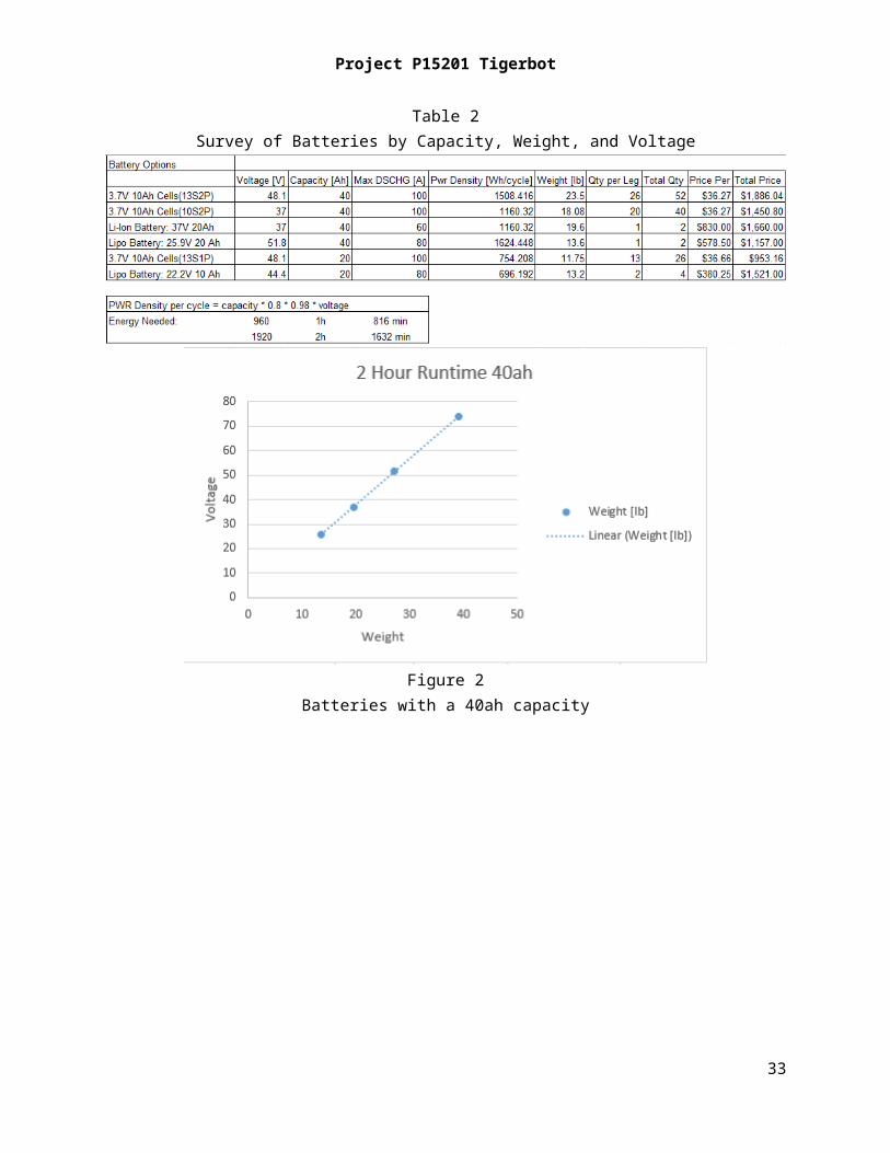
Battery - Originally after initial research the battery chemistry that suited Tigerbot was Lithium Iron Phosphate. Table 1 shows information on the battery chemistries researched. However further research revealed that calculations for power density included lifetime cycle information. Lithium Iron Phosphate has a much higher cycle life than most chemistries and it is very stable. When cycle life information was removed from the calculation there was not a significant difference in power density between Lithium Iron Phosphate and Lithium Polymer. Overall Lithium Polymer is significantly lighter than Lithium Iron Phosphate making it ideal for Robotics applications. Completing a survey of batteries with the characteristics of voltage and weight in mind classified by capacity, showed a linear trend as voltage increases to weight increase. This makes sense as the increase in voltage is achieved through the addition of extra cells. This is shown in Table 2 and Figures 2 through 4. Further research found a suitable candidate by estimation as shown in Table 3.
Table 1Survey of Battery Chemistries
Table 2Survey of Batteries by Capacity, Weight, and Voltage
25

Project P15201 Tigerbot
Figure 2Batteries with a 40ah capacity
Figure 3Batteries with a 20ah capacity
26

Project P15201 Tigerbot
Figure 4Batteries with runtime less than 1 hour
Table 3Battery Candidate
As a team a mock tour was simulated walking the EE floor giving a detailed tour and timed. Based on the timing data, the ratio between talking and walking is 60/40. Initially the current draw of the servos was overestimated. For walking we assumed a full current draw in a worst case scenario and multiplied it by the ideal voltage desired to get a walking power as shown in Equation 1. For standing we assumed the upper half of the robot would be negligible and took into account on the draw of the lower half. We assumed a reduced current draw for six servo’s due to locking features and a full draw for the remaining two. This gives an estimate for power draw standing as shown in Equation 2. Taking 60% of standing power and 40% of walking power gives the total estimate for power draw shown in Equation 3.
Power Walking = Max Current of Servo’s * Ideal Voltage of Battery Equation 1
Power Standing = (70% * Max Current * 6 + Max Current * 2) * Voltage Equation 2
60% * Power Standing + 40% * Power Walking = Total Power Estimate Equation 3
However because the overall design is not yet finalized, we are delaying battery purchase and instead will conduct a tethered test to accurately gauge current draw.
27

Project P15201 Tigerbot
Fixed Supply:
For the initial weeks of MSD II we plan to use a 60V 60A bench supply loaned from the EE Lab Manager Ken Synder.
Regulation:
In addition to finding a battery for servo power, we plan to have the servos and the sensors/computing on separate supplies. Two batteries will be required for the servos at high voltage and current. For sensors and computing an additional Lithium Polymer battery at lower voltage around 7.4V will be used with two regulation boards to deliver stable 3.3V and 5V. To meet this goal we have selected two regulator boards from Pololu that are synchronous switching step-down (or buck) regulators. All images are taken from the supplier websites.
28

Project P15201 Tigerbot
29

Project P15201 Tigerbot
30

Project P15201 Tigerbot
Testing:Force Sensing Resistors (FSR) Test Plan
Platform for implementation of FSR concept: Shoe and Breadboard/Breakout board
Schedule:Phase 1:Implement ADC board via breadboard and breakout board.Implement connections for FSR and to MicrocontrollerTest connection and data collectionPhase 2: Mount to test platformEstablish connection to microcontrollerPhase 3:Run desired testsPhase 4:Analyze results
Definition of Outcome:
Read voltage: Voltage levels agree with manufacturer table and characterizationsEven distributed voltage: Assumption of operation is that voltage levels will be relatively equal between the four active FSR’s with even distribution of weight.Reasonable response time: Response of FSR’s can be processed fast enough to properly react to data. Ideally under 0.5 sec.
31

Project P15201 Tigerbot
Encoder Test Plan:
Platform for Implementation: Test Joint
Schedule:Phase 1:Implement potentiometer using the ADC setupTest FeedbackPhase 2:How to connect to join and implement connectionPhase 3:Run joint test with teamPhase 4:Analyze result
Definition of Outcome:
Read voltage: Voltage feedback is acquirableCharacterize Voltage: Voltage can be translated to a position
32
Project P15201 Tigerbot
Battery Test Plan:
Phase 1: Measure Current of Joint TestPhase 2:Upon completion of design run second and third testsPhase 3:Select battery to meet measurements
Definition of Outcome:
Read current: Measure current draw of servo’s in each case scenario to quantify total power draw.
33

Project P15201 Tigerbot
Schedule:
34

Project P15201 Tigerbot
Update: The first round of PCB’s for the ADC and FSR’s have been placed and received as well
as the components to populate them. As of Friday 2/6/15 one ADC board has been completed and is ready for testing. Additional parts like the FSR’s are on order.
Remaining elements to be designed are the teensy breakout board and power distribution board. For teensy breakout board, we have created the teensy footprint in PCB artist in lieu of importing a library. Final PCB designs should be completed by week 3.
With the majority of design complete the remaining work is layout, testing, and embedded programing. We are coordinating with the Computer engineers to tackle the remaining embedded programming so they can focus on further ROS development. We hope to have some sort of sensor demo within a week.
35