ee 261 – introduction to logic circuits module #4 page 1 ee 261 – introduction to logic circuits...
TRANSCRIPT

EE 261 – Introduction to Logic Circuits Module #4Page 1
EE 261 – Introduction to Logic Circuits
Module #4 – Boolean Algebra• Topics
A. Boolean Algebra Formation
B. Minterms
C. Maxterms
D. Circuit Synthesis
E. Logic Minimization
F. Timing Hazards
• Textbook Reading Assignments
4.1–4.4
• Practice Problems 4.2, 4.3, 4.7, 4.9, 4.14, 4.18, 4.19
• Graded Components of this Module 3 homeworks, 3 discussions, 1 quiz
(all online)

EE 261 – Introduction to Logic Circuits Module #4Page 2
EE 261 – Introduction to Logic Circuits
Module #4 – Boolean Algebra
• What you should be able to do after this module
Understand basic logic operations and theorems governing them Create a Minterm list, Maxterm list, Canonical SOP, and POS from a Truth Table Synthesize a logic diagram from either a Minterm list, Maxterm list, SOP, or POS Manipulate a logic diagram to have the same functionality using different gates Create a minimized logic expression using a K-map Add logic to a logic expression to avoid timing hazards

EE 261 – Introduction to Logic Circuits Module #4Page 3
Boolean Algebra
• Boolean Algebra
- formulated by mathematician George Boole in 1854
- basic relationships & manipulations for a two-value system
• Switching Algebra
- adaptation of Boolean Logic to analyzer and describe behavior of relays
- Claude Shannon of Bell Labs in 1938
- this works for all switches (mechanical or electrical)
- we generally use the terms "Boolean Algebra" & "Switching Algebra" interchangeably

EE 261 – Introduction to Logic Circuits Module #4Page 4
Boolean Algebra
• What is Algebra
- the basic set of rules that the elements and operators in a system follow
- the ability to represent unknowns using variables
- the set of theorems available to manipulate expressions
• Boolean
- we limit our number set to two values (0, 1)
- we limit our operators to AND, OR, INV

EE 261 – Introduction to Logic Circuits Module #4Page 5
Boolean Algebra
• Axioms
- also called "Postulates"
- minimal set of basic definitions that we assume to be true
- all other derivations are based on these truths
- since we only have two values in our system, we typically define an axiom and then its complement (A1 & A1')
EE 261 – Introduction to Logic Circuits Module #4Page 6
Boolean Algebra
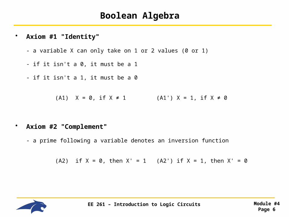
• Axiom #1 "Identity"
- a variable X can only take on 1 or 2 values (0 or 1)
- if it isn't a 0, it must be a 1
- if it isn't a 1, it must be a 0
(A1) X = 0, if X ≠ 1 (A1') X = 1, if X ≠ 0
• Axiom #2 "Complement"
- a prime following a variable denotes an inversion function
(A2) if X = 0, then X' = 1 (A2') if X = 1, then X' = 0

EE 261 – Introduction to Logic Circuits Module #4Page 7
Boolean Algebra
• Axiom #3 "AND"
- also called "Logical Multiplication"
- a dot (·) is used to represent an AND function
• Axiom #4 "OR"
- also called "Logical Addition"
- a plus (+) is used to represent an OR function
• Axiom #5 "Precedence"
- multiplication precedes addition
(A3) 0·0 = 0 (A3') 1+1 = 1
(A4) 1·1 = 1 (A4') 0+0 = 0
(A5) 0·1 = 1·0 = 0 (A5') 0+1 = 1+0 = 1

EE 261 – Introduction to Logic Circuits Module #4Page 8
Boolean Algebra
• Theorems
- Theorems use our Axioms to formulate more meaningful relationships & manipulations
- a theorem is a statement of TRUTH
- these theorems can be proved using our Axioms
- we can prove most theorems using "Perfect Induction"
- this is the process of plugging in every possible input combination and observing the output
F=A∙B + C
A B C 0 0 0 0 0 1 0 1 0 0 1 1 1 0 0 : 1 1 1

EE 261 – Introduction to Logic Circuits Module #4Page 9
Boolean Algebra
• Theorem #1 "Identity" (T1) X+0 = X (T1') X·1 = X
• Theorem #2 "Null Element" (T2) X+1 = 1 (T2') X·0 = 0
• Theorem #3 "Idempotency" (T3) X+X = X (T3') X·X = X
• Theorem #4 "Involution" (T4) (X')' = X
• Theorem #5 "Complements" (T5) X+X' = 1 (T5') X·X' = 0
X X’ F=A+B0 0 00 1 11 0 11 1 1
X X’ F=A∙B0 0 00 1 01 0 01 1 1

EE 261 – Introduction to Logic Circuits Module #4Page 10
Boolean Algebra
• Theorem #6 "Commutative" (T6) X+Y = Y+X (T6') X·Y = Y·X
• Theorem #7 "Associative" (T7) (X+Y)+Z= X+(Y+Z) (T7') (X · Y) · Z= X · (Y · Z)
• Theorem #8 "Distributive" (T8) X·(Y+Z) = X·Y + X·Z (T8') (X+Y)·(X+Z) = X + Y·Z

EE 261 – Introduction to Logic Circuits Module #4Page 11
Boolean Algebra
• Theorem #9 "Covering"
(T9) X + X·Y = X (T9') X·(X+Y) = X
• Theorem #10 "Combining" (T10) X·Y + X·Y' = X (T10') (X+Y)·(X+Y') = X
• Theorem #11 "Consensus"
(T11) X·Y + X'·Z + Y·Z= X·Y + X'·Z (T11') (X+Y)·(X'+Z)·(Y+Z) = (X+Y) ·(X'+Z)

EE 261 – Introduction to Logic Circuits Module #4Page 12
Boolean Algebra
• Notes on the Theorems
- T9/T9' and T10/T10' are used heavily in logic minimization
- these theorems can be useful for making routing more reasonable
- these theorems can reduce the number of gates in a circuit
- they can also change the types of gates that are used

EE 261 – Introduction to Logic Circuits Module #4Page 13
Boolean Algebra
• More Theorem's - there are more generalized theorems available for large number of variables
T13, T14, T15
- one of the most useful is called "DeMorgan's Theorem"
• DeMorgan's Theorem - this theorem states a method to convert between AND and OR gates using inversions on the input / output

EE 261 – Introduction to Logic Circuits Module #4Page 14
Boolean Algebra
• DeMorgan's Theorem
Part 1: an AND gate whose output is complemented is equivalent to
an OR gate whose inputs are complemented
Part 2: an OR gate whose output is complemented is equivalent to
an AND gate whose inputs are complemented
=
=

EE 261 – Introduction to Logic Circuits Module #4Page 15
Boolean Algebra
• Complement
- complementing a logic function will give outputs that are inverted versions of the original function
ex) A B F F'
0 0 0 1 0 1 0 1 1 0 0 1 1 1 1 0
- DeMorgan's Theorem also gives us a generic formula to complement any expression:
- for a Logic function F, we can get F' by :
1) Swapping all + and ·
2) Complementing all Variables
- KEEP THE PARENTHESIS ORDER OF THE ORGINAL FUNCTION !!!

EE 261 – Introduction to Logic Circuits Module #4Page 16
Boolean Algebra
• Complement
- Example: Complement the Function F
ex) A B F F'
0 0 0 1 0 1 0 1 1 0 0 1 1 1 1 0
We know:
F = A · B
We swap + and · first, then we complement all variables
F' = A' + B'
- This is the same as putting an inversion bubble on the output of the logic diagram →

EE 261 – Introduction to Logic Circuits Module #4Page 17
Boolean Algebra
• Duality
- An Algorithm to switch between Positive Logic and Negative Logic
- Duality means that the logic expression is exactly the same even though the circuitry has been altered to produce Complementary Logic
- The steps are:
- for a Logic function F, we can get FD by :
1) Swapping all + and ·
2) Swapping all 0's and 1's
- Ex) F = A · B (Positive Logic)
We swap + and · first, then swap any 0's and 1's
FD = A + B (Negative Logic or "Dual")

EE 261 – Introduction to Logic Circuits Module #4Page 18
Boolean Algebra
• Complement vs. Duality, What is the difference?

EE 261 – Introduction to Logic Circuits Module #4Page 19
Minterms
• Truth Tables
Row A B C F 0 0 0 0 1 Row We assign a "Row Number" for each entry starting at 0 1 0 0 1 0 2 0 1 0 0 Variables We enter all input combinations in ascending order. 3 0 1 1 1 We use straight binary with the MSB on the left
4 1 0 0 1
5 1 0 1 0 Function We say the output is a function of the input variables
6 1 1 0 1 F(A,B,C)
7 1 1 1 1
n = the number of input variables
2n = the number of input combinations
EE 261 – Introduction to Logic Circuits Module #4Page 20
Minterms
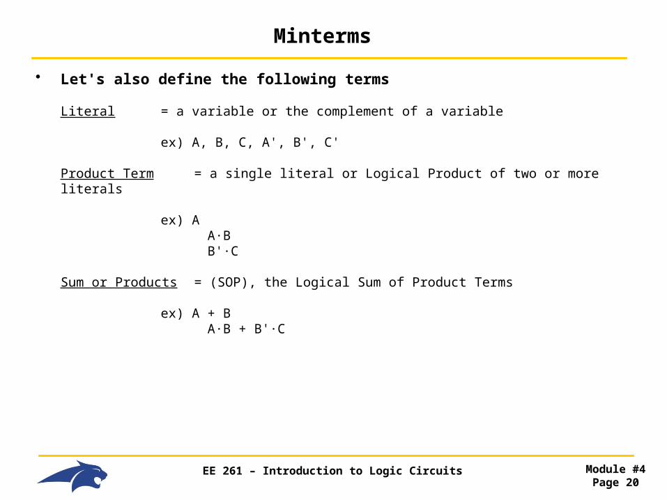
• Let's also define the following terms
Literal = a variable or the complement of a variable ex) A, B, C, A', B', C'
Product Term = a single literal or Logical Product of two or more literals ex) A A·B B'·C
Sum or Products = (SOP), the Logical Sum of Product Terms ex) A + B A·B + B'·C

EE 261 – Introduction to Logic Circuits Module #4Page 21
Minterms
• Minterm - a normal product term w/ n-literals
- a Minterm is written for each ROW in the truth table
- there are 2n Minterms for a given truth table
- we write the literals as follows:
- if the input variable is a 0 in the ROW, we complement the Minterm literal
- if the input variable is a 1 in the ROW, we do not complement the Minterm literal
- for each ROW, we use a Logical Product on all of the literals to create the Minterm

EE 261 – Introduction to Logic Circuits Module #4Page 22
Minterms
• Minterm
Row A B C Minterm F 0 0 0 0 A'·B'·C' F(0,0,0) 1 0 0 1 A'·B'·C F(0,0,1) 2 0 1 0 A'·B·C' F(0,1,0) 3 0 1 1 A'·B·C F(0,1,1) 4 1 0 0 A·B'·C' F(1,0,0) 5 1 0 1 A·B'·C F(1,0,1) 6 1 1 0 A·B·C' F(1,1,0) 7 1 1 1 A·B·C F(1,1,1)
• Canonical Sum
- we Logically Sum all Minterms that correspond to a Logic 1 on the output
- the Canonical Sum represents the entire Logic Expression when the Output is TRUE
- this is called the "Sum of Products" or SOP

EE 261 – Introduction to Logic Circuits Module #4Page 23
Minterms
• Minterm List
- we can also describe the full logic expression using a list of Minterms corresponding to a Logic 1
- we use the Σ symbol to indicate we are writing a Minterm list
- we list the Row numbers corresponding to a Logic 1
Row A B C Minterm F 0 0 0 0 A'·B'·C' 0 1 0 0 1 A'·B'·C 1 2 0 1 0 A'·B·C' 1 3 0 1 1 A'·B·C 0 4 1 0 0 A·B'·C' 0 5 1 0 1 A·B'·C 0 6 1 1 0 A·B·C' 1 7 1 1 1 A·B·C 0
F = ΣA,B,C (1,2,6) = (A'·B'·C) + (A'·B·C') + (A·B·C')
- this is also called the "ON-set"
- this list is very verbose and NOT minimized using our Axioms and Theorems (more on this later…)

EE 261 – Introduction to Logic Circuits Module #4Page 24
Maxterms
• Let's define the following terms
Sum Term = a single literal or a Logical Sum of two or more literals
ex) A A + B'
Product of Sums = (POS), the Logical Product of Sum Terms
ex) (A+B)·(B'+C)
Normal Term = a term in which no variable appears more than once
ex) "Normal
A·BA + B'
ex) "Non-Normal"
A·B·B'A + A'

EE 261 – Introduction to Logic Circuits Module #4Page 25
Maxterms
• Maxterm - a Normal Sum Term w/ n-literals
- a Maxterm is written for each ROW in the truth table
- there are 2n Maxterms for a given truth table
- we write the literals as follows:
- if the input variable is a 0 in the ROW, we do not complement the Maxterm literal
- if the input variable is a 1 in the ROW, we complement the Maxterm literal
- for each ROW, we use a Logical Sum on all of the literals to create the Maxterm

EE 261 – Introduction to Logic Circuits Module #4Page 26
Maxterms
• Maxterm
Row A B C Minterm Maxterm F 0 0 0 0 A'·B'·C' A+B+C F(0,0,0) 1 0 0 1 A'·B'·C A+B+C' F(0,0,1) 2 0 1 0 A'·B·C' A+B'+C F(0,1,0) 3 0 1 1 A'·B·C A+B'+C' F(0,1,1) 4 1 0 0 A·B'·C' A'+B+C F(1,0,0) 5 1 0 1 A·B'·C A'+B+C' F(1,0,1) 6 1 1 0 A·B·C' A'+B'+C F(1,1,0) 7 1 1 1 A·B·C A'+B'+C' F(1,1,1)
• Canonical Product
- we Logically Multiply all Maxterms that correspond to a Logic 0 on the output
- the Canonical Product represents the entire Logic Expression when the Output is TRUE
- this is called the "Product of Sums" or POS

EE 261 – Introduction to Logic Circuits Module #4Page 27
Maxterms
• Maxterm List
- we can also describe the full logic expression using a list of Maxterms corresponding to a Logic 0
- we use the π symbol to indicate we are writing a Maxterm list
- we list the Row numbers corresponding to a Logic 0
Row A B C Minterm Maxterm F 0 0 0 0 A'·B'·C' A+B+C 0 1 0 0 1 A'·B'·C A+B+C' 1 2 0 1 0 A'·B·C' A+B'+C 1 3 0 1 1 A'·B·C A+B'+C' 0 4 1 0 0 A·B'·C' A'+B+C 0 5 1 0 1 A·B'·C A'+B+C' 0 6 1 1 0 A·B·C' A'+B'+C 1 7 1 1 1 A·B·C A'+B'+C' 0
F = πA,B,C (0,3,4,5,7) = (A+B+C) · (A+B'+C') · (A'+B+C) · (A'+B+C') · (A'+B'+C')
- this is also called the "OFF-set"
- this list is very verbose and NOT minimized

EE 261 – Introduction to Logic Circuits Module #4Page 28
Maxterms
• Maxterm vs. Minterm
- a Maxterm is the Dual of a Minterm
- this implies an inversion
- however, by writing a POS for when the Maxterm is a Logic 0, we perform another inversion
- these two inversions yield the original logic expression for when the function is 1
- SOP = POS

EE 261 – Introduction to Logic Circuits Module #4Page 29
Maxterms
• Minterms & Maxterm
- we now have 5 ways to describe a Logic Expression
1) Truth Table 2) Minterm List 3) Canonical Sum 4) Maxterm List 5) Canonical Product
- these all give the same information
• Converting Between Minterms and Maxterms
- Minterms and Maxterms are Duals
- this means we can convert between then easily using DeMorgan's duality theorem
- converting a SOP to its dual gives Negative Logic
- converting a POS to its dual gives Negative Logic

EE 261 – Introduction to Logic Circuits Module #4Page 30
Circuit Synthesis
• Circuit Synthesis - there are 5 ways to describe a Logic Expression
1) Truth Table 2) Minterm List 3) Canonical Sum 4) Maxterm List 5) Canonical Product
- we can directly synthesis circuits from SOP and POS expressions
SOP = AND-OR structure POS = OR-AND structure

EE 261 – Introduction to Logic Circuits Module #4Page 31
Circuit Synthesis
• Circuit Synthesis - For the given Truth Table, synthesize the SOP and POS Logic Diagrams
Row A B Minterm Maxterm F 0 0 0 A'·B' A+B 1 1 0 1 A'·B A+B' 1 2 1 0 A·B' A'+B 0 3 1 1 A·B A'+B' 0
Minterm List & SOP Maxterm List & POS
F = ΣA,B (0,1) = A'·B' + A'·B F = πA,B (2,3) = (A'+B) · (A'+B')

EE 261 – Introduction to Logic Circuits Module #4Page 32
Circuit Synthesis
• Circuit Manipulation - we can manipulate our Logic Diagrams to give the same logic expression but use different logic gates
- this can be important when using technologies that:
- only have certain gates (i.e., INV, NAND, NOR) - have certain gates that are faster than others (i.e., NAND-NAND, NOR-NOR)
- we can convert a SOP/POS logic diagram into a NAND-NAND or NOR-NOR structure

EE 261 – Introduction to Logic Circuits Module #4Page 33
Circuit Synthesis
• Common Circuit Manipulation "DeMorgan's"
=
=

EE 261 – Introduction to Logic Circuits Module #4Page 34
Circuit Synthesis
• Common Circuit Manipulation "Moving Inversion Bubbles"

EE 261 – Introduction to Logic Circuits Module #4Page 35
Circuit Synthesis
• Common Circuit Manipulation "Inserting Double Inversion Bubbles"

EE 261 – Introduction to Logic Circuits Module #4Page 36
Circuit Synthesis
• Common Circuit Manipulation "Bubbles can be moved to either side of an Inverter"

EE 261 – Introduction to Logic Circuits Module #4Page 37
Logic Minimization
• Logic Minimization
- We've seen that we can directly translate a Truth Table into a SOP/POS and in turn a Logic Diagram
- However, this type of expression is NOT minimized
ex) Row A B Minterm Maxterm F 0 0 0 A'·B' A+B 1 1 0 1 A'·B A+B' 1 2 1 0 A·B' A'+B 0 3 1 1 A·B A'+B' 0
Minterm List & SOP Maxterm List & POS
F = ΣA,B (0,1) = A'·B' + A'·B F = πA,B (2,3) = (A'+B) · (A'+B')

EE 261 – Introduction to Logic Circuits Module #4Page 38
Logic Minimization
• Logic Minimization
- using our Axioms and Theorems, we can manually minimize the expressions…
Minterm List & SOP Maxterm List & POS
F = A'·B' + A'·B F = (A'+B) · (A'+B')
F = A'·(B'+B) = A' F = A' + (B'·B) = A'
- doing this by hand can be difficult and requires that we recognize patterns associated with our 5 Axioms and our 15+ Theorems
• Karnaugh Maps
- a graphical technique to minimize a logic expression

EE 261 – Introduction to Logic Circuits Module #4Page 39
Logic Minimization
• Karnaugh Map Creation
- we create an array with 2n cells
- each cell contain the value of F at a particular input combination
- we label each Row and Column so that we can easily determine the input combinations
- each cell only differs from its adjacent neighbors by 1-variable
A
B 0 1
0
1
List Variables Top-to-Bottom List Input Combinations for the Variables for each Row/Column

EE 261 – Introduction to Logic Circuits Module #4Page 40
Logic Minimization
• Karnaugh Map Creation
A
B 0 1
0
1
We can put redundant labeling for when a variable is TRUE. This helps when creating larger K-maps
We can also put the Truth Table Row number so that copying the Truth Table values into the K-map is straight-forward
0
1
2
3
B
AA’
B’

EE 261 – Introduction to Logic Circuits Module #4Page 41
Logic Minimization
• Karnaugh Map Creation
- we can now copy in the Function values
Row A B Minterm Maxterm F 0 0 0 A'·B' A+B 11 0 1 A'·B A+B' 12 1 0 A·B' A'+B 03 1 1 A·B A'+B' 0
- at this point, the K-map is simply the same information as in the Truth Table
- we could write a SOP or POS directly from the K-map if we wanted to
1 0
1 0
A
B 0 1
0
1
0
1
2
3
B
A

EE 261 – Introduction to Logic Circuits Module #4Page 42
Logic Minimization
• Karnaugh Map Creation
- we can create 3 variable K-Maps
- notice the input combination numbering in order to achieve no more than 1-variable difference between cells
AB
C 00 01
0
1
0
1
2
3
C
A
6
7
4
5
11 10
B

EE 261 – Introduction to Logic Circuits Module #4Page 43
Logic Minimization
• Karnaugh Map Creation
- we can create 4 variable K-Maps
AB
CD 00 01
00
01
0
1
4
5
C
A
12
13
8
9
11 10
B
3
2
7
6
15
14
11
10
11
10
D

EE 261 – Introduction to Logic Circuits Module #4Page 44
Logic Minimization
• Karnaugh Map Minimization
- we can create a minimized SOP logic expression by performing the following:
1) Circle adjacent 1's in groups of power-of-2
- powers of 2 means 1,2,4,8,16,…. - adjacent means neighbors above, below, right, left (not diagonal) - we can wrap around the ends to form group - this is called "Combining Cells"
2) We then write a Product Term for each circle following:
- if the circle covers areas where the variable is 0, we enter a complemented literal in the product term - if the circle covers areas where the variable is 1, we enter an non-complemented literal in the product term
- if the circle covers areas where the variable is both a 0 and 1, we can exclude the variable from the product term
3) We then Sum the Product Terms

EE 261 – Introduction to Logic Circuits Module #4Page 45
Logic Minimization
• Karnaugh Map Minimization
- let's write a minimized SOP for the following K-map
1 0
1 0
A
B 0 1
0
1
0
1
2
3
B
A
- this circle covers 2 cells- the circle covers:
- where A=0, so the literal is A'- where B=0 and 1, so the literal is excluded
- our final SOP expression is
F = A'

EE 261 – Introduction to Logic Circuits Module #4Page 46
Logic Minimization
• Karnaugh Map Minimization
0 1
1 0
AB
C 00 01
0
1
0
1
2
3
C
A
0
1
6
7
0
1
4
5
11 10
B
- this circle covers 1 cell - the circle covers:
- where A=0, so the literal is A'- where B=1, so the literal is B
- where C=0, so the literal is C'
- The product term for this circle is : A'·B·C'
- this circle covers 2 cells - the circle covers:
- where A=1, so the literal is A- where B=0 and 1, exclude the literal
- where C=1, so the literal is C
- The product term for this circle is : A·C
- this circle covers 2 cells- the circle covers:
- where A=0 and 1, exclude the literal- where B=0, so the literal is B'- where C=1, so the literal is C
- The product term for this circle is : B'·C
- our final minimized SOP expression is
F = A'·B·C' + A·C + B'·C

EE 261 – Introduction to Logic Circuits Module #4Page 47
Logic Minimization
• Karnaugh Map Minimization
- the original Canonical SOP for this Map would have been
F = A'·B'·C + A'·B·C' + A·B'·C + A·B·C
- our minimized SOP expression is now:
F = A'·B·C' + A·C + B'·C
- this minimization resulted in:
- one less input on the OR gate - one less AND gate - two AND gates having 2 inputs instead of 3
0 1
1 0
AB
C 00 01
0
1
0
1
2
3
C
A
0
1
6
7
0
1
4
5
11 10
B

EE 261 – Introduction to Logic Circuits Module #4Page 48
Logic Minimization
• 2-Variable K-Map Example
- write a minimal SOP for the following truth table
Row A B Minterm Maxterm F 0 0 0 A'·B' A+B 01 0 1 A'·B A+B' 12 1 0 A·B' A'+B 13 1 1 A·B A'+B' 1
- we first copy in the output values into the K-map
0 1
1 1
A
B 0 1
0
1
0
1
2
3
B
A

EE 261 – Introduction to Logic Circuits Module #4Page 49
Logic Minimization
• 2-Variable K-Map Example
- we then circle groups of 1's in order to find the Product Term for each circle
0 1
1 1
A
B 0 1
0
1
0
1
2
3
B
A - this circle covers 2 cells - the circle covers:
- where A=1, so the literal is A- where B=0 and 1, exclude the literal
- The product term for this circle is : A
- this circle covers 2 cells - the circle covers:
- where A=0 and 1, exclude the literal - where B=1, so the literal is B
- The product term for this circle is : B

EE 261 – Introduction to Logic Circuits Module #4Page 50
Logic Minimization
• 2-Variable K-Map Example
- we then write a SOP expression for each circles' Product Term
0 1
1 1
A
B 0 1
0
1
0
1
2
3
B
A
The minimized SOP is : A + B

EE 261 – Introduction to Logic Circuits Module #4Page 51
Logic Minimization
• 3-Variable K-Map Example
- write a minimal SOP expression for the following truth table
Row A B C Minterm Maxterm F 0 0 0 0 A'·B'·C' A+B+C 0 1 0 0 1 A'·B'·C A+B+C' 1 2 0 1 0 A'·B·C' A+B'+C 1 3 0 1 1 A'·B·C A+B'+C' 0 4 1 0 0 A·B'·C' A'+B+C 1 5 1 0 1 A·B'·C A'+B+C' 1 6 1 1 0 A·B·C' A'+B'+C 1 7 1 1 1 A·B·C A'+B'+C' 1
0 1
1 0
AB
C 00 01
0
1
0
1
2
3
C
A
1
1
6
7
1
1
4
5
11 10
B

EE 261 – Introduction to Logic Circuits Module #4Page 52
Logic Minimization
• 3-Variable K-Map Example
0 1
1 0
AB
C 00 01
0
1
0
1
2
3
C
A
1
1
6
7
1
1
4
5
11 10
B
- this circle covers 2 cells - the circle covers:
- where A=0/1, so exclude literal- where B=1, so the literal is B
- where C=0, so the literal is C'
- The product term for this circle is : B·C'
- this circle covers 4 cells - the circle covers:
- where A=1, so the literal is A- where B=0/1, so exclude the literal
- where C=0/1, so exclude the literal - The product term for this circle is : A
- this circle covers 2 cells - the circle covers:
- where A=0 and 1, exclude the literal- where B=0, so the literal is B'- where C=1, so the literal is C
- The product term for this circle is : B'·C
- our final minimized SOP expression is
F = A + B·C' + B'·C

EE 261 – Introduction to Logic Circuits Module #4Page 53
Logic Minimization
• 4-Variable K-Map Example
- write a minimal SOP expression for the following truth table
Row A B C D F 0 0 0 0 0 0 1 0 0 0 1 1 2 0 0 1 0 0 3 0 0 1 1 1 4 0 1 0 0 0 5 0 1 0 1 0 6 0 1 1 0 0 7 0 1 1 1 0 8 1 0 0 0 1 9 1 0 0 1 1 10 1 0 1 0 1 11 1 0 1 1 1 12 1 1 0 0 0 13 1 1 0 1 0 14 1 1 1 0 0 15 1 1 1 1 0
0 0
1 0
AB
CD 00 01
00
01
0
1
4
5
C
A
0
0
12
13
1
1
8
9
11 10
B
1 0
0 0
3
2
7
6
0
0
15
14
1
1
11
10
11
10
D

EE 261 – Introduction to Logic Circuits Module #4Page 54
Logic Minimization
• 4-Variable K-Map Example
0 0
1 0
AB
CD 00 01
00
01
0
1
4
5
C
A
0
0
12
13
1
1
8
9
11 10
B
1 0
0 0
3
2
7
6
0
0
15
14
1
1
11
10
11
10
D
- this circle covers 4 cells - the circle covers:
- where A=1, so the literal is A- where B=0, so the literal is B'
- where C=0/1, so exclude the literal - where D=0/1, so exclude the literal
- The product term for this circle is : A·B'
- this circle covers 4 cells - the circle covers:
- where A=0/1, so exclude the literal - where B=0, so the literal is B'
- where C=0/1, so exclude the literal - where D=1, so the literal is D
- The product term for this circle is : B'·D
- our final minimized SOP expression is
F = A·B' + B'·D
EE 261 – Introduction to Logic Circuits Module #4Page 55
Logic Minimization (POS)
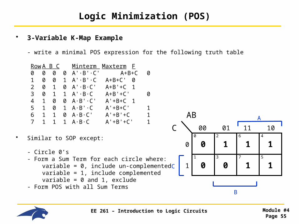
• 3-Variable K-Map Example
- write a minimal POS expression for the following truth table
Row A B C Minterm Maxterm F 0 0 0 0 A'·B'·C' A+B+C 0 1 0 0 1 A'·B'·C A+B+C' 0 2 0 1 0 A'·B·C' A+B'+C 1 3 0 1 1 A'·B·C A+B'+C' 0 4 1 0 0 A·B'·C' A'+B+C 1 5 1 0 1 A·B'·C A'+B+C' 1 6 1 1 0 A·B·C' A'+B'+C 1 7 1 1 1 A·B·C A'+B'+C' 1
• Similar to SOP except:
- Circle 0’s- Form a Sum Term for each circle where: variable = 0, include un-complemented variable = 1, include complemented variable = 0 and 1, exclude- Form POS with all Sum Terms
0 1
0 0
AB
C 00 01
0
1
0
1
2
3
C
A
1
1
6
7
1
1
4
5
11 10
B

EE 261 – Introduction to Logic Circuits Module #4Page 56
Logic Minimization (POS)
• 3-Variable K-Map Example
0 1
0 0
AB
C 00 01
0
1
0
1
2
3
C
A
1
1
6
7
1
1
4
5
11 10
B
- this circle covers 2 cells - the circle covers:
- where A=0, the literal is A - where B=0, the literal is B
- where C=0 and 1, so it is excluded
- The sum term for this circle is : (A + B)
- our final minimized POS expression is
F = (A + B)·(A+C’)
- this circle covers 2 cells - the circle covers:
- where A=0, the literal is A - where B=0 and 1, so it is excluded
- where C=1, the literal is C’
- The sum term for this circle is : (A + C’)

EE 261 – Introduction to Logic Circuits Module #4Page 57
Logic Minimization
• K-Map Logic Minimization
- we can use K-maps to write a minimal SOP (and POS)
- however, we've seen that there is a potential for redundant Product Terms
- we need to define what it is to be "Minimized"
0 0
0 1
AB
C 00 01
0
1
0
1
2
3
C
A
1
1
6
7
1
0
4
5
11 10
Is this circle necessary?

EE 261 – Introduction to Logic Circuits Module #4Page 58
Logic Minimization
• K-Map Logic Minimization
Minimal Sum - No other expression exists that has
- fewer product terms - fewer literals
Imply - a logic function P "implies" a function F if
- every input combination that causes P=1 - also causes F=1 - may also cause more 1's
- we say that:
- "F includes P" - "F covers P" - "F => P"

EE 261 – Introduction to Logic Circuits Module #4Page 59
Logic Minimization
• K-Map Logic Minimization
Prime Implicant - a Normal Product Term of F (i.e., a P that implies F) where if any variable is removed from P, the resulting product does NOT imply F
- K-maps: a circled set of 1's that cannot be larger without circling 1 or more 0's
Prime Implicant Theorem
- a Minimal Sum is a sum of Prime Implicants
BUT Does not need to include ALL prime Implicants

EE 261 – Introduction to Logic Circuits Module #4Page 60
Logic Minimization
• K-Map Logic Minimization
Complete Sum - the product of all Prime Implicants (not minimized)
Distinguished 1-Cell
- an "input combination" that is covered by only ONE Prime Implicant
Essential Prime Implicant
- a Prime Implicant that covers one or more "Distinguished 1-Cells"
NOTE: - the sum of Essential Prime Implicants is the Minimal Sum
- this means we're done minimizing

EE 261 – Introduction to Logic Circuits Module #4Page 61
Logic Minimization
• K-Map Logic Minimization
Steps for Minimization
1) Identify All Prime Implicants
2) Identify the Distinguished 1-Cells
3) Identify the Essential Prime Implicants
4) Create the SOP using Essential Prime Implicants

EE 261 – Introduction to Logic Circuits Module #4Page 62
Minimal Sum
• 4-Variable K-Map Example
0 0
0 0
AB
CD 00 01
00
01
0
1
4
5
C
A
0
1
12
13
0
1
8
9
11 10
B
0 1
0 0
3
2
7
6
1
0
15
14
0
0
11
10
11
10
D
What is the complete sum?
F = A·C’·D + A·B·D + B·C·D
What are the distinguished 1 cells?
Cell 7 & Cell 9
What are the essential Prime Implicants?
A·C’·D and B·C·D
What is the minimal sum:
F = A·C’·D + B·C·D

EE 261 – Introduction to Logic Circuits Module #4Page 63
Logic Minimization
• Don't Cares
- sometimes it doesn't matter whether the output is a 1 or 0 for a certain input combination
- we can take advantage of this during minimization by treating the don't care as a 1 or 0 depending on whether it makes finding Prime Implicants easier
- We denote X = Don't Care
Row A B C Minterm Maxterm F 0 0 0 0 A'·B'·C' A+B+C 0 1 0 0 1 A'·B'·C A+B+C' 0 2 0 1 0 A'·B·C' A+B'+C 0 3 0 1 1 A'·B·C A+B'+C' X 4 1 0 0 A·B'·C' A'+B+C 1 5 1 0 1 A·B'·C A'+B+C' 1 6 1 1 0 A·B·C' A'+B'+C 1 7 1 1 1 A·B·C A'+B'+C' X
0 0
0 X
AB
C 00 01
0
1
0
1
2
3
C
A
1
X
6
7
1
1
4
5
11 10
B

EE 261 – Introduction to Logic Circuits Module #4Page 64
Timing Hazards
• Hazards
- we've only considered the Static (or steady state) values of combination logic
- in reality, there is delay present in the gates
- this can cause different paths through the circuit which arrive at different times at the input to a gate
- this delay can cause an unwanted transition or "glitch" on the output of the circuit
- this behavior is known as a "Timing Hazard"
- a Hazard is the possibility of an input combination causing a glitch
EE 261 – Introduction to Logic Circuits Module #4Page 65
Timing Hazards
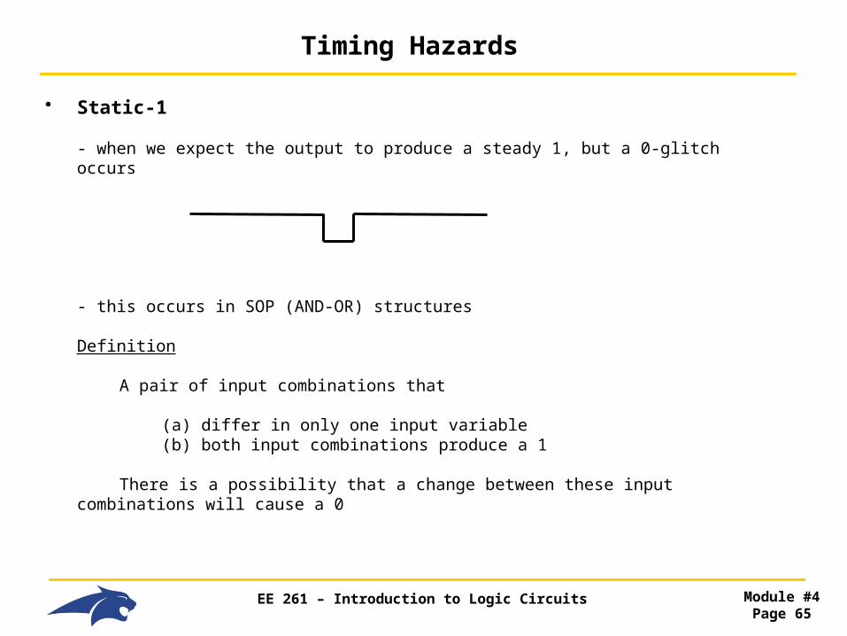
• Static-1
- when we expect the output to produce a steady 1, but a 0-glitch occurs
- this occurs in SOP (AND-OR) structures
Definition
A pair of input combinations that
(a) differ in only one input variable (b) both input combinations produce a 1
There is a possibility that a change between these input combinations will cause a 0

EE 261 – Introduction to Logic Circuits Module #4Page 66
Timing Hazards
• Static-0
- when we expect the output to produce a steady 0, but a 1-glitch occurs
- this occurs in POS (OR-AND) structures
Definition
A pair of input combinations that
(a) differ in only one input variable (b) both input combinations produce a 0
There is a possibility that a change between these input combinations will cause a 1

EE 261 – Introduction to Logic Circuits Module #4Page 67
Timing Hazards
• Hazards and K-maps
- K-maps graphically show input combinations that vary by only one variable
- it is easy to see when adjacent cells have 1's and have a potential Timing Hazard
- this is a Minimal Sum, BUT, what about the transition from A·B·C to A·B·C'?
- there is a Timing Hazard present!!!
0 0
0 1
AB
C 00 01
0
1
0
1
2
3
C
A
1
1
6
7
1
0
4
5
11 10
B

EE 261 – Introduction to Logic Circuits Module #4Page 68
Timing Hazards
• Hazards and K-maps
- the solution is to add an additional product term (Prime Implicant) to cover the transition
- this ensures that the output is valid while transitioning between any input combination
- this is NOT a Minimal Sum, but it is Hazard Free
0 0
0 1
AB
C 00 01
0
1
0
1
2
3
C
A
1
1
6
7
1
0
4
5
11 10
B

EE 261 – Introduction to Logic Circuits Module #4Page 69
Timing Hazards
• Dynamic Hazards
- when we undergo a transition on the output but multiple transitions occur
- this is again due to multiple paths w/ different delays from input to output
- typically is larger leveled logic
- Solution: If the circuit is Static Hazard Free, then it is Dynamic Hazard Free

EE 261 – Introduction to Logic Circuits Module #4Page 70
Timing Hazards
• Hazard Prevention
- adding redundant Prime Implicants will prevent Hazards but can sometime add too much logic
- we can also perform delay matching through the circuit by inserting buffers so that the delay is the same at each level of logic

EE 261 – Introduction to Logic Circuits Module #4Page 71
Module Overview
• Combinational Logic Design Flow
- We now have all the pieces for a complete design process
1) Design Specifications : description of what we want to do
2) Truth Table : listing the logical operation of the system
3) Describe using : creating the logic expression SOP/POS/Minterm/Maxterm
4) Logic Minimization : K-maps
5) Logic Manipulation : Convert to desired technology (NAND/NAND, …)
6) Hazard Prevention

EE 261 – Introduction to Logic Circuits Module #4Page 72
Module Overview
• Topics
Boolean Algebra - Axioms - 1-variable Theorems - Multi-variable Theorems - DeMorgan's - Duality
Term - Literals - Product Term - SOP - Sum Term - POS - Normal Term - Variable
Minterms & SOP
Maxterms & POS
Synthesis and Manipulation
K-Maps - creating - imply - Prime Implicant - Prime Implicant Theorem - Distinguished 1-Cell - Essential Prime Implicant Don't Cares
Hazards - Static-0 - Static-1 - Dynamic - Prevention - redundant Prime Implicant - delay matching
Combination Logic Design Flow