edwards epx hivac series dry vacuum pumps - ideal vac · epx hivac series dry vacuum pumps ... 1.6...
TRANSCRIPT

A419-00-880Issue F Original
Instruction Manual
EPX HiVac Series Dry Vacuum Pumps
Description EPX EPX TWIN
Item Number Item Number
EPX180L A419-41-xxx A419-61-xxx
EPX180N A419-42-xxx A419-62-xxx
EPX180LE A419-43-xxx A419-63-xxx
EPX180NE A419-44-xxx A419-64-xxx
EPX500L A419-51-xxx A419-71-xxx
EPX500N A419-52-xxx A419-72-xxx
EPX500LE A419-53-xxx A419-73-xxx
EPX500NE A419-54-xxx A419-74-xxx
(505)872-0037idealvac.com
idealvac.com

Declaration of Conformity
We, Edwards, Manor Royal, Crawley, West Sussex RH10 9LW, UK declare under our sole responsibility that the product(s) EPX High Vacuum Dry Pump EPX EPX Twin EPX180L A419-41-xxx A419-61-xxx EPX180N A419-42-xxx A419-62-xxx EPX180LE A419-43-xxx A419-63-xxx EPX180NE A419-44-xxx A419-64-xxx EPX500L A419-51-xxx A419-71-xxx EPX500N A419-52-xxx A419-72-xxx EPX500LE A419-53-xxx A419-73-xxx EPX500NE A419-54-xxx A419-74-xxx
in combination with the following TIM units: C3, E73, SPI, TEL, LAM, HIT, MCM and also pumps with no TIM unit fitted
to which this declaration relates is in conformity with the following standard(s) or other normative document(s)
EN1012-2 (1997) Safety Requirements, Vacuum Pumps. EN61010-1 (2001) Safety Requirements for Electrical Equipment for Measurement,
Control and Laboratory Use. EN61326 (1998) Electrical Equipment for Measurement, Control and Laboratory (Industrial location, Use – EMC Requirements Class A Emissions) UL61010A-1 Electrical Equipment for Laboratory Use; Part 1 – General (First edition) Requirements SEMI S2-0302 Product Safety Assessment SEMI S8-0701 Ergonomic Assessment SEMI F47-0200 Voltage Sag Immunity
following the provisions of
2006/95/EC Low Voltage Directive. 2004/108/EC Electromagnetic Compatibility Directive. 98/37/EC Machinery Safety Directive.
Barrie Brewster, Technical Manager – Burgess Hill Products Date and Place
This product has been manufactured under a quality system registered to ISO9001
P200
-00-
060
Issu
e C 19 January 2009, Burgess Hill

© Edwards Limited 2007. All rights reserved. Page iEdwards and the Edwards logo are trademarks of Edwards Limited.
ContentsA419-00-880 Issue F
Contents
Section Page
1 Introduction ....................................................................................... 1
1.1 Scope and definitions ................................................................................................... 11.2 Description ................................................................................................................ 21.2.1 The EPX L ................................................................................................................. 31.2.2 The EPX LE ................................................................................................................ 31.2.3 The EPX N ................................................................................................................. 31.2.4 The EPX NE ................................................................................................................ 31.3 Pump protection sensors ............................................................................................... 41.4 LED status indicators .................................................................................................... 41.5 Connections ..............................................................................................................121.6 Control and monitoring ................................................................................................121.7 EPX pump labels ........................................................................................................121.8 End user controller .....................................................................................................13
2 Technical data .................................................................................. 15
2.1 General ...................................................................................................................152.2 Performance .............................................................................................................152.3 Electrical data ...........................................................................................................162.4 Cooling-water supply ...................................................................................................172.5 Nitrogen purge system (EPX N series pumps) .......................................................................172.6 Materials in contact with process gases .............................................................................17
3 Installation ....................................................................................... 27
3.1 Safety .....................................................................................................................273.2 Unpack and inspect .....................................................................................................273.3 Securing the EPX pump ................................................................................................283.4 Connect the inlet to your process system ...........................................................................283.5 Connect the outlet to your exhaust extraction system ...........................................................293.6 Nitrogen purge (EPX N series pumps) ................................................................................303.7 Leak test the system ...................................................................................................313.8 Connect the cooling-water supply ...................................................................................313.9 Connect to your emergency stop circuit ............................................................................323.10 Connect the EPX pump to the electrical supply ...................................................................333.11 Connect to your control equipment .................................................................................343.11.1 Inputs .....................................................................................................................343.11.2 Outputs ...................................................................................................................35
4 End User Controller (EUC) and Pump Display Terminal (PDT) menus ................... 37
4.1 Introduction .............................................................................................................374.2 General operation ......................................................................................................384.3 The CANCEL button .....................................................................................................384.4 Display text and variable text ........................................................................................384.5 Wrap-around .............................................................................................................394.6 Timeout ..................................................................................................................394.7 Menu structure ..........................................................................................................394.8 Example ..................................................................................................................40
5 Operation ........................................................................................ 51
5.1 Introduction .............................................................................................................515.2 Flammable and toxic gases (EPX N series pumps) .................................................................52
dcs/
8031
/08/
08

A419-00-880 Issue F
Page ii © Edwards Limited 2007. All rights reserved.Edwards and the Edwards logo are trademarks of Edwards Limited.
Contents
5.3 Start-up ..................................................................................................................525.4 Manual shut-down ......................................................................................................535.5 Status and fault indications ...........................................................................................535.6 Unplanned shutdown and alarms .....................................................................................53
6 Maintenance ..................................................................................... 55
6.1 Safety .....................................................................................................................566.2 Maintenance plan .......................................................................................................566.3 Inspect the pipelines and connections ..............................................................................576.4 Cleaning the pump ......................................................................................................576.5 Service the EPX pump ..................................................................................................586.6 Fault finding .............................................................................................................59
7 Storage and disposal ........................................................................... 61
7.1 Storage ...................................................................................................................617.2 Disposal ...................................................................................................................62
8 Service, spares and accessories .............................................................. 63
8.1 Introduction .............................................................................................................638.2 Service ....................................................................................................................63
Index .............................................................................................. 65
For return of equipment, complete the HS Forms at the end of this manual.
Illustrations
Figure Page1 Process compatibility chart ............................................................................................ 22 The EPX L dry vacuum pump ........................................................................................... 53 EPX twin 180L installation details - position of additional exhaust port for EPX twin variants ............. 64 EPX L labels (refer to Table 3) ......................................................................................... 85 EPX E dry pump .........................................................................................................106 EPX N series dry pump .................................................................................................117 End User Controller (EUC) display ....................................................................................128 Speed curve (mbar - Pa) ...............................................................................................189 Speed curve (Torr) ......................................................................................................1810 Speed curve (mbar - Pa) EPX and EPX Twin ........................................................................1911 Speed curve (Torr) EPX and EPX Twin ...............................................................................1912 EPX L installation dimensions (EPX500L shown) ....................................................................2013 EPX LE installation dimensions (EPX500LE shown) .................................................................2114 EPX N installation dimensions (EPX500N shown) ...................................................................2215 EPX NE installation dimensions (EPX500NE shown) ................................................................2316 Location of the pump centre of gravity from centre of the top of the inlet flange ..........................2417 Gas module schematic .................................................................................................2518 Schematic diagram of emergency stop facility ....................................................................3219 EUC and PDT menu logic ...............................................................................................4120 Switch on menu .........................................................................................................4221 Switch off menu .........................................................................................................4222 Normal menu ............................................................................................................4323 Status menu .............................................................................................................4424 Control menu ............................................................................................................4525 Setup menu (sheet 1 of 2) .............................................................................................4626 Software version ........................................................................................................4827 Select units menu .......................................................................................................49

© Edwards Limited 2007. All rights reserved. Page iiiEdwards and the Edwards logo are trademarks of Edwards Limited.
ContentsA419-00-880 Issue F
28 Select line menu ........................................................................................................50
Tables
Table Page1 LEDs on the EPX pumps ................................................................................................. 72 Connections ............................................................................................................... 73 EPX L pump labelling information (Refer to Figure 4) ............................................................. 94 EPX E (Refer to Figure 5) ..............................................................................................105 EPX N (Refer to Figure 6) ..............................................................................................116 General ...................................................................................................................157 Performance .............................................................................................................158 Electrical data ...........................................................................................................169 Cooling water supply ...................................................................................................1710 Nitrogen supply .........................................................................................................1711 Materials in contact with process gas ...............................................................................1712 Tool connectors and mating tool connector kits ...................................................................3413 Tool input signals to the pump system ..............................................................................3414 Output signals from the pump system ...............................................................................3515 EUC and PDT menu structure .........................................................................................3916 Maintenance plan .......................................................................................................5817 Fault finding .............................................................................................................5918 EPX EUC alarms and warnings .........................................................................................6019 Accessory kits ...........................................................................................................63

This page has been intentionally left blank.
A419-00-880 Issue F
Page iv © Edwards Limited 2007. All rights reserved.Edwards and the Edwards logo are trademarks of Edwards Limited.

© Edwards Limited 2007. All rights reserved. Page 1Edwards and the Edwards logo are trademarks of Edwards Limited.
IntroductionA419-00-880 Issue F
1 Introduction1.1 Scope and definitions
This manual provides installation, operation and maintenance instructions for the Edwards EPX HiVac Series of dry vacuum pumps (these are abbreviated to ‘EPX pump’ for the remainder of this manual). You must use the EPX pump as specified in this manual.
Read this manual before you install, operate, and maintain the EPX pump. Important safety information is highlighted as WARNING and CAUTION instructions; you must obey these instructions. The use of WARNINGS and CAUTIONS is defined below.
Statements and instructions in the following manual that refer to the EPX variant pump are equally applicable to the EPX Twin pump unless stated otherwise. Differences between the two pump variants are restricted to power characteristics, external connections to the exhaust extraction system and external dimensions/appearance.
CAUTIONCautions are given where failure to observe the instruction could result in damage to the equipment, associated equipment and process.
Throughout this manual, page, figure and table numbers are sequential.
The units used throughout this manual conform to the SI international system of units of measurement; US equivalent units of measurement are also given.
The following IEC warning labels appear on the pump or in the manual:
WARNING
Warnings are given where failure to observe the instruction could result in injury or death to people.
Warning - refer to accompanying documentation.
Warning - risk of electric shock.
Warning - hot surfaces.
Warning - danger of injury from rotating parts.

A419-00-880 Issue F
Page 2 © Edwards Limited 2007. All rights reserved.Edwards and the Edwards logo are trademarks of Edwards Limited.
Introduction
Figure 1 - Process compatibility chart
1.2 Description
CAUTIONThe EPX series of pumps are not suitable for pumping Xenon.
Warning - heavy object.
Warning - corrosive material.
Warning - toxic material.
Warning - flammable material.
WARNING
Edwards take no responsibility for damage or injury caused by improper use of the equipment.
WARNING
The EPX Dry Vacuum Pump must only be used for the applications depicted in Figure 1. Incorrect use of the EPX system could invalidate your warranty. Contact your local Edwards representative if you are unsure whether the EPX system is appropriate for your application.
The EPX pump should not be used to pump explosive mixtures or pyrophoric gases.

© Edwards Limited 2007. All rights reserved. Page 3Edwards and the Edwards logo are trademarks of Edwards Limited.
IntroductionA419-00-880 Issue F
The EPX pump system operates at pressures between atmospheric and ultimate vacuum, with no lubricating or sealing fluid in the pumping chamber. This ensures a clean pumping system without back-migration of oil or fluid into the system being evacuated.
Between 1 bar and 0.2 mbar, the EPX Twin pump offers a significant pumping performance advantage over the standard EPX pump. As such, the EPX Twin pump is ideal for use on load lock applications, rapid cycling applications etc.
The stator of the pump and the enclosed motor are cooled by an integrated water cooling circuit. The EPX pump is therefore suitable for applications in cleanroom environments where fan cooling is unacceptable. The cooling water supply and return pipelines are connected to the pump by water connectors (customer specified) (Figure 2, items 4 and 9). Cooling water must be provided commensurate with environmental conditions (humidity and temperature) such that the dewpoint is not reached. Refer to Table 9 for the water supply specifications.
Refer to Figure 2 and 4. The pump incorporates an EMC supply filter and an inverter drive, which provides and controls the electrical supply to the pump-motor. LEDs on the front cover identify the status of the EPX pump: (refer to Figure 4, items 2, 3, 4, and 5 and Table 1). Motor speed depends on the pressure at the pump inlet. When the pump is started with the inlet pressure at or close to atmospheric pressure, the motor accelerates to a speed which is limited by the current which can be supplied by the inverter drive. As the pressure at the inlet is reduced, the motor speed increases, until it eventually reaches its preset maximum speed. If the pressure at the inlet increases, the motor will slow down again.
The EPX pump is supported by four vibration isolators (Figure 2, item 7).
Pump protection sensors automatically shut down the pump if a fault condition arises: refer to Section 1.3.
The EPX pump is available in a number of different variants. The nomenclature is arranged to help identify which variants are suitable for which applications, and which method of control is required for the pump. The four base variants are described in more detail below:
1.2.1 The EPX L
This pump is for use on clean duty applications pumping inert gas mixtures, such as loadlock, whereby control is provided by the process tool interface. (Refer to Figure 2).
1.2.2 The EPX LE
This pump is for use on clean duty applications such as loadlock, and is augmented with an End User Controller (EUC). The End User Controller enables local control for stand-alone use as well as the ability to connect to a fab-wide network for remote control and monitoring. A Pump Display Terminal (PDT) may also be used with the End User Controller to facilitate local control. (Refer to Figure 5).
1.2.3 The EPX N
This is fitted with a gas module that supplies nitrogen purge gas to the shaft seal and pump mechanism areas to provide dilution of process gases for the light duty applications specified in Figure 1. (Refer to Figure 5, Table 5 and Section 3.6 for further information).
1.2.4 The EPX NE
This system is a light process application pump with network and local control capability through the EUC as described in Section 1.2.2. (Refer to Figure 5).
The four base variants, the L, LE, N and NE are also available in two capacities, 180 m3/hr (letter designation prefixed with 180 for example EPX180LE) and 500 m3/hr (letter designation prefixed with 500 for example EPX500N).
The EPX pump can also be specified as either 200/208 V or 400 V compatible and a choice of either 1/4 inch BSP, 3/8 inch BSP, 9/16 inch BSP quick connect water fittings or no quick connects.

A419-00-880 Issue F
Page 4 © Edwards Limited 2007. All rights reserved.Edwards and the Edwards logo are trademarks of Edwards Limited.
Introduction
The EPX pump is fitted with a Tool Interface Module (TIM), which allows ‘plug and play’ connection with all major process tools. This communication includes control and monitoring of the EPX by the tool for example Run, Stop, Alarm.
A number of different tool interface options (TIMs) can be specified when the pump is first ordered: SPI, C3, TEL, E73, MCM or HIT.
Note: The LE and NE versions of the EPX pump can be operated via the end user controller and so do not require a TIM for operation.
The illustrations throughout this manual show the E73 variant of the TIM.
1.3 Pump protection sensors
A thermal snap-switch located within the pump, monitors the temperature of the body of the EPX pump. When the temperature of the body exceeds a preset limit, the snap-switch operates, generating an alarm and causing the pump to stop.
When the EPX pump is automatically shut down by a pump protection sensor, the Alarm LED is lit (Figure 4, item 5).
On the EPX N series of pumps, a nitrogen purge flow switch is fitted to the Gas Module to monitor the total purge flow to the pump. If the purge flow drops below 12 slm, the warning LED on the front panel (or EUC if fitted), will light (Figure 4, item 4). The pump will continue to run.
1.4 LED status indicators
Refer to Table 1 and Figure 4.
WARNING
For EPX N-series pumps, if the pump has been fitted with a C3 or E73 tool interface, there is no provision for warnings, generated by the pump, to be passed onto the tool. The installer must fit suitable monitoring equipment to check the nitrogen purge flow, as detailed in Section 3.
WARNING
For EPX N-series pumps, the nitrogen purge flow switch in the Gas Module is set to 12 slm. The flow switch provides an indication that a flow in excess of 12 slm is present, but gives no guarantee that there is sufficient flow to meet the process requirements. The flow switch is not a guaranteed safety interlock.
WARNING
When the pump protection sensor operates, only the electrical supply of the pump-motor is switched off; the EPX is not isolated from the electrical supply.

© Edwards Limited 2007. All rights reserved. Page 5Edwards and the Edwards logo are trademarks of Edwards Limited.
IntroductionA419-00-880 Issue F
Figure 2 - The EPX L dry vacuum pump
1. Pump inlet2. Lifting eyebolt (two positions)3. Protective earth stud (M8)4. Cooling water inlet5. TIM6. Mains supply cable7. Vibration isolator (four positions)8. Exhaust9. Cooling water outlet

A419-00-880 Issue F
Page 6 © Edwards Limited 2007. All rights reserved.Edwards and the Edwards logo are trademarks of Edwards Limited.
Introduction
Figure 3 - EPX twin 180L installation details - position of additional exhaust port for EPX twin variants
© Edwards Limited 2007. All rights reserved. Page 7Edwards and the Edwards logo are trademarks of Edwards Limited.
IntroductionA419-00-880 Issue F
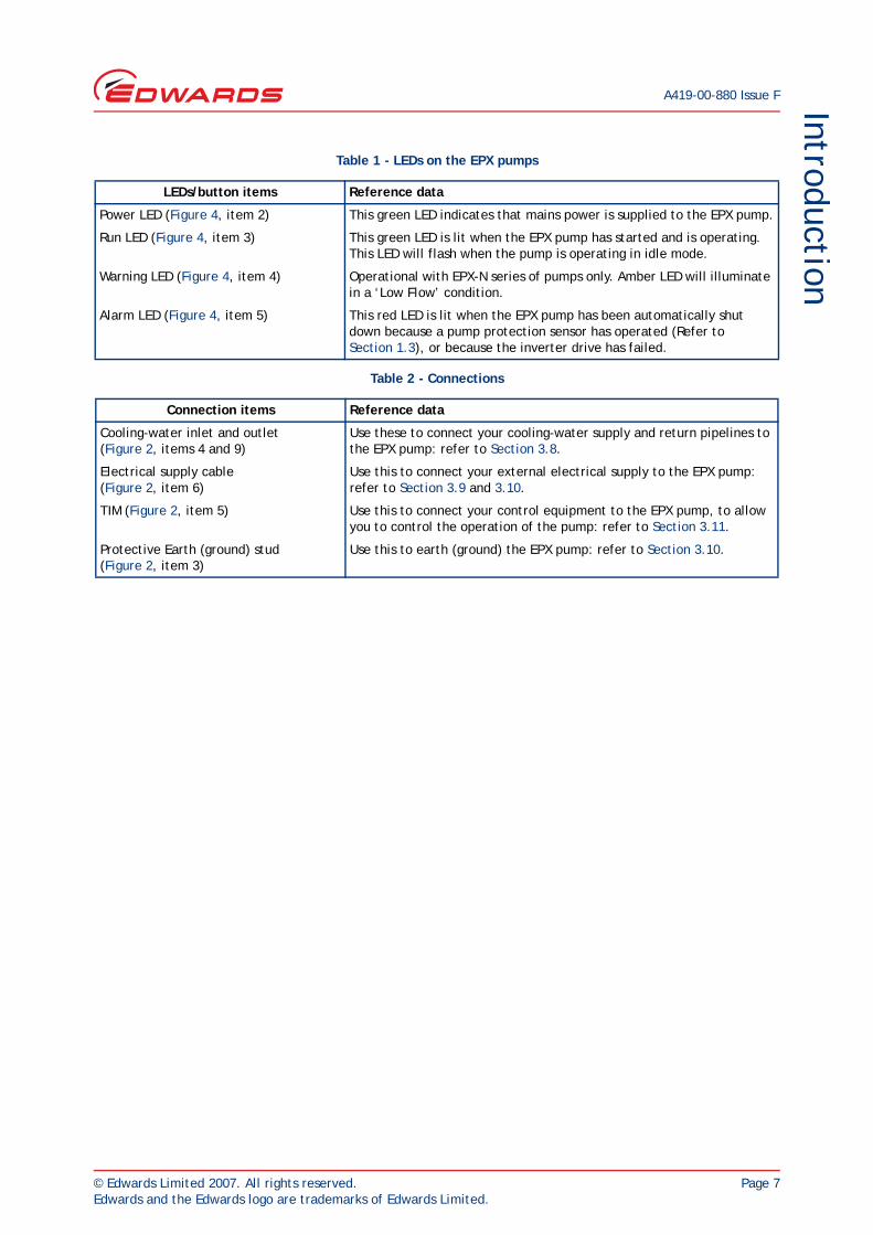
Table 1 - LEDs on the EPX pumps
LEDs/button items Reference data
Power LED (Figure 4, item 2) This green LED indicates that mains power is supplied to the EPX pump.
Run LED (Figure 4, item 3) This green LED is lit when the EPX pump has started and is operating. This LED will flash when the pump is operating in idle mode.
Warning LED (Figure 4, item 4) Operational with EPX-N series of pumps only. Amber LED will illuminate in a ‘Low Flow’ condition.
Alarm LED (Figure 4, item 5) This red LED is lit when the EPX pump has been automatically shut down because a pump protection sensor has operated (Refer to Section 1.3), or because the inverter drive has failed.
Table 2 - Connections
Connection items Reference data
Cooling-water inlet and outlet (Figure 2, items 4 and 9)
Use these to connect your cooling-water supply and return pipelines to the EPX pump: refer to Section 3.8.
Electrical supply cable (Figure 2, item 6)
Use this to connect your external electrical supply to the EPX pump: refer to Section 3.9 and 3.10.
TIM (Figure 2, item 5) Use this to connect your control equipment to the EPX pump, to allow you to control the operation of the pump: refer to Section 3.11.
Protective Earth (ground) stud (Figure 2, item 3)
Use this to earth (ground) the EPX pump: refer to Section 3.10.

A419-00-880 Issue F
Page 8 © Edwards Limited 2007. All rights reserved.Edwards and the Edwards logo are trademarks of Edwards Limited.
Introduction
Figure 4 - EPX L labels (refer to Table 3)

© Edwards Limited 2007. All rights reserved. Page 9Edwards and the Edwards logo are trademarks of Edwards Limited.
IntroductionA419-00-880 Issue F
Table 3 - EPX L pump labelling information (Refer to Figure 4)
Number Label Name Description
1 Pump details This provides specific information about the pump including: pump type; code number; serial number; pump weight; year of manufacture; and name and address of the manufacturer. It also includes electrical supply requirements, and compliance marks.
2 Power The power LED. See Table 1 for details.
3 Run The run LED. See Table 1 for details.
4 Warning The warning LED. See Table 1 for details.
5 Alarm The alarm LED. See Table 1 for details.
6 Warning - risk of electric shock
Do not remove cover until 4 minutes after disconnection of the power.
7 Warning - risk of electric shock
Do not remove cover until 4 minutes after disconnection of the power.
8 Status LED label Status LED label.
9 and 10 Lifting point The pump must be lifted using the eyebolts on the pump and suitable lifting equipment.
11 Warning - risk of high temperature
Surface temperatures can exceed 65 oC during pump operation.
12 Direction of rotation Arrow shows the correct direction of rotation of the rotor.
13 Warning - danger of injury from rotating parts
Turn off and lock-out all power prior to servicing.
14 Water in The cooling water supply pipeline connects to the pump at this location.
15 Protective earth stud This equipment must have a second protective earth. See Section 3.10.
16 Pump interface Tool Interface Module (TIM) fits in this position. The pump may be controlled through this. See Section 3.11.
17 Warning - risk of electric shock
Do not remove cover until 4 minutes after disconnection of the power.
18 Warning - risk of electric shock
Do not remove cover until 4 minutes after disconnection of the power.
19 Warning - thermal shock If the pump has overheated or the cooling water has failed, connecting cooling water to a hot pump will cause severe damage to the pump.Always allow the pump to cool for at least 20 minutes before connecting cooling water.
20 Water out The cooling water return pipeline connects to the pump at this location.
21 Product label Product name.

A419-00-880 Issue F
Page 10 © Edwards Limited 2007. All rights reserved.Edwards and the Edwards logo are trademarks of Edwards Limited.
Introduction
Figure 5 - EPX E dry pump
Table 4 - EPX E (Refer to Figure 5)
Number Description
1 Label - Product name.
2 XLR Connector - This may be used to connect a fab-wide network to allow remote monitoring and control of the EPX Dry Pump.
3 Label - Warning do not remove cover until 4 minutes after disconnecting power from the pump.
4 RJ12 Connector - This is used to connect the optional, external, PDT to the EPX Dry Pump.
5 End User Controller accessory - The End User Controller has an on-board display and keypad that allows local control of the EPX Dry Pump. Refer to Section 1.8 and 4 for the operation of this.

© Edwards Limited 2007. All rights reserved. Page 11Edwards and the Edwards logo are trademarks of Edwards Limited.
IntroductionA419-00-880 Issue F
Figure 6 - EPX N series dry pump
Table 5 - EPX N (Refer to Figure 6)
Number Description
1 Pipe fitting - Nitrogen supply to the seal purge.
2 Label - Warning; If the pump has overheated or the cooling water has failed, connecting cooling water to a hot pump will cause severe damage to the pump.Always allow the pump to cool for at least 20 minutes before connecting the cooling water.
3 Label - Warning; do not remove cover until 4 minutes after disconnecting power from the pump.
4 Gas supply fitting - Connect the gas supply to this connection. This compression fitting accepts 1/4 inch (6.35 mm) diameter tube. Ensure that the tube used is suitable for your application.
5 Label - Gas Module identifier.
6 Pipe fitting - Nitrogen supply to the gas ballast.

A419-00-880 Issue F
Page 12 © Edwards Limited 2007. All rights reserved.Edwards and the Edwards logo are trademarks of Edwards Limited.
Introduction
Figure 7 - End User Controller (EUC) display
1.5 Connections
Refer to Table 2 and Figure 4.
1.6 Control and monitoring
The EPX L and N series of pumps cannot be manually operated; they must be controlled and monitored by external control equipment, which must be connected to the EPX pump through the TIM (Figure 2, item 5).
The EPX E series of pumps can be manually operated using the EUC local display and keypad, or remotely using a PDT, if fitted; it can also be controlled and monitored over the network, which connects to the EPX pump through the Network connector (Figure 5, item 2). When the EPX ‘E’ series of pumps is controlled via the TIM, the EUC simply monitors the status of the pump.
The EPX pump is compatible with Fabworks 32.
1.7 EPX pump labels
Refer to Table 3 and Figure 4.
1. Run button2. Display3. Down button4. CANCEL button5. Up button
6. ENTER button7. Menu buttons Status, Normal, Control, Setup8. Menu selected LEDs9. Status LEDs Local Control, Warning, Alarm10. Stop button

© Edwards Limited 2007. All rights reserved. Page 13Edwards and the Edwards logo are trademarks of Edwards Limited.
IntroductionA419-00-880 Issue F
1.8 End user controller
The End User Controller (EUC) allows manual control of the EPX pump and also displays the pump status. Refer to Figure 7 which shows the front panel of the EUC display.
Use the run button (Figure 7, item 1) to start the EPX pump. The run button has an LED which is on when the EPX pump is running. Use the stop button (Figure 7, item 10) to stop the pump.
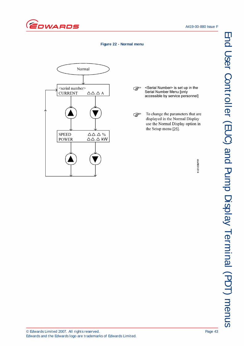
The display (Figure 7, item 2) shows two lines of text; each line is 16 characters long. In normal operation, the Normal display is shown; the Normal display has two pages, and each has two lines. Each page of the Normal display shows the status of one or more EPX EUC sensors or internal clocks and counters. As supplied, the first page of Normal display shows the pump serial number and pump current. It is possible to change the information shown on the Normal display.
At any time, press one of the four menu buttons (Figure 7, item 7) to select a new menu. Then use the up (Figure 7, item 5), down (Figure 7, item 3), ENTER (Figure 7, item 6) and CANCEL (Figure 7, item 4) buttons to move through the menu. The appropriate menu selected LED (Figure 7, item 8) is on when the corresponding menu is in use.
Use the menu (Figure 7, item 7), up (Figure 7, item 5), down (Figure 7, item 3), CANCEL (Figure 7, item 4) and ENTER (Figure 7, item 6) buttons as described below. Refer to Section 4 for a full definition of the menu structures and the display formats.
Status: Press this button to select the Status menu. This menu displays the current pump status.
Normal: Press this button to select the Normal display.
Control: Press this button to select the Control menu, then take control or release control of the pumping system (refer to Section 4).
Setup: Press this button to select the Setup menu. In this menu it is possible to display parameters (such as the pressure units used when pressures are displayed).
Enter (6): Use this button to select a currently displayed menu option or to enter a currently displayed parameter.
Cancel (4): Use this button to cancel the currently displayed menu or option and return to the previous menu or option.
Up (5)/Down (3): Use these buttons to move up or down menu options or to increase or decrease a displayed parameter.
The status LEDs (Figure 7, item 9) show the current status of the EPX system.
Alarm: This LED shows when an alarm condition exists.
Warning: This LED shows when a warning condition exists.
Local control: This LED is on when the EUC has control of the EPX system.
The ALARM and WARNING LEDs flash when the corresponding alarm or warning condition first occurs. When acknowledging the condition, the corresponding LED goes on permanently. For most alarms and warnings, if the condition clears (that is, the fault which caused the condition is no longer present), the corresponding LED goes off once the condition has been acknowledged.

A419-00-880 Issue F
Page 14 © Edwards Limited 2007. All rights reserved.Edwards and the Edwards logo are trademarks of Edwards Limited.
This page has been intentionally left blank.

© Edwards Limited 2007. All rights reserved. Page 15Edwards and the Edwards logo are trademarks of Edwards Limited.
Technical dataA419-00-880 Issue F
2 Technical data2.1 General
2.2 Performance
Table 6 - General
EPX180 EPX500
Dimensions Refer to Figure 12, 13, 14, and 15
Mass:
EPX LEPX NEPX LEEPX NE
43.5 kg45.5 kg44.6 kg46.6 kg
45.2 kg47.2 kg46.3 kg48.3 kg
Inlet ISO63 ISO160
Inlet fittings (not supplied) One ISO63 centring ring.4 Claw clamps
One ISO160 centring ring.8 Claw clamps
Outlet NW25
Ambient operating temperature range 5 to 40 oC, 41 to 104 oF
Maximum ambient operating humidity 90% RH non-condensing
Noise level <59 dB(A)
Vibration <0.25 g
Maximum operating tilt angle 5o
Handling The pump must not be laid on its side or invertedTopple angle >15°
Maximum exhaust pressure <1200 mbar absolute
Lubricating oil The EPX pump has a sealed lubricating oil system. For health and safety information, refer to the Material Safety Data Sheet for Fomblin
6/6: MSDS No. P120-01-015.
Ingress protection IP44 (with inlet and exhaust connected)(E-series pumps are rated to IP40)
Table 7 - Performance
EPX180 EPX500
Warm-up time(to nominal performance)
30 minutes
Peak pumping speed 170 m3 hr-1 103.0 cfm 500 m3 hr-1 294.3 cfm
Ultimate vacuum*
* The time taken to reach ultimate vacuum is dependent upon vacuum system cleanliness and foreline conductance.
<1 x 10⁻⁴ mbar,<1 x 10⁻² Pa,
<7.5 x 10⁻⁵ Torr
<1 x 10⁻⁶ mbar,<1 x 10⁻⁴ Pa,
<7.5 x 10⁻⁷ Torr
Maximum leak rate 1 x 10⁻⁵ mbar l s-1, 1 x 10⁻³ Pa l s-1, 2.1 x 10⁻⁸ atm ft3 min-1

A419-00-880 Issue F
Page 16 © Edwards Limited 2007. All rights reserved.Edwards and the Edwards logo are trademarks of Edwards Limited.
Technical data
2.3 Electrical data
Table 8 - Electrical data
Electrical items Reference data
Electrical supply 200/208 V, 50/60 Hz, 400 V 50/60 Hz 3-phase
Voltage tolerance ±10%
Electrical power
Maximum Power 3.0 kW
Nominal Power at Ultimate (EPX)
L-variant 1.4 kW
N-variant 1.6 kW
Nominal Power at Ultimate (EPX twin)
L-variant 2.30 kW
N-variant 2.55 kW
Fuse/ isolator rating *
* Maximum recommended fuse rating; requires a multipole isolator with a minimum contact gap of 3 mm. The mains disconnect device AIC (Amperes Interrupting Capacity) must be rated to at least 10 000 A. See clause 13 of SEMI S2 - 0200 and SEMI S8 for further details.
200 V 17.5 A current limiting time delay Class CC fuse, rated 600 V
400 V 10 A current limiting time delay Class CC fuse, rated 600 V
Installation (overvoltage) category Class II
Pollution degree 2
Minimum protective earth (ground) cable rating 32 A
Electrical supply interface Per customer specification
Power cable 4 core terminated with 2.5 mm2 bootlace ferrules
TIM
Parallel pump interface As per TIM interface supplied (refer to Section 3.11)
Nominal voltage rating 24 V
Shut-down thermal snap-switch
Opening temperature 70 oC, 158 oF
Closing temperature 59 oC, 138 oF

© Edwards Limited 2007. All rights reserved. Page 17Edwards and the Edwards logo are trademarks of Edwards Limited.
Technical dataA419-00-880 Issue F
2.4 Cooling-water supply
2.5 Nitrogen purge system (EPX N series pumps)
2.6 Materials in contact with process gases
Table 9 - Cooling water supply
Cooling-water items Reference data
Maximum supply pressure 7 barg, 7 x 10⁵ Pa, 100 psig
Minimum required pressure differential across supply and return 2 bar, 2 x 10⁵ Pa, 30 psi
Maximum supply temperature 35 oC
Minimum supply temperature 15 oC
Maximum particle size in supply 0.03 mm2, 4.6 x 10⁻⁵ inch2
Typical heat removed from EPX pump 1.3 kW, 5118 btu h-1
Minimum water flow rate 2 l min-1, 31.7 US gallons h-1
Connectors
Inlet Per customer specification
Outlet Per customer specification
Table 10 - Nitrogen supply
Gas Module Items Reference Data
Nitrogen supply interface 1/4 inch (6.35 mm) Tube
Maximum supply pressure 7 barg, 7 x 10⁵ Pa, 100 psig
Minimum supply pressure 3.0 barg, 3 x 10⁵ Pa, 45 psig
Minimum purity 0.9995
Typical nitrogen purge flow at a supply pressure of 3.0 barg 25 slm (17 slm Gas Ballast)
Table 11 - Materials in contact with process gas
Material items Reference data
Pump-body Hard anodised aluminium
Pump rotor Hard anodised aluminium
Internal shaft seals PTFE coated aluminium
O-rings Viton fluoroelastomer
Pump shaft Carbon steel
Gas module nitrogen components Stainless steel, hard anodised aluminium and viton
A419-00-880 Issue F
Page 18 © Edwards Limited 2007. All rights reserved.Edwards and the Edwards logo are trademarks of Edwards Limited.
Technical data
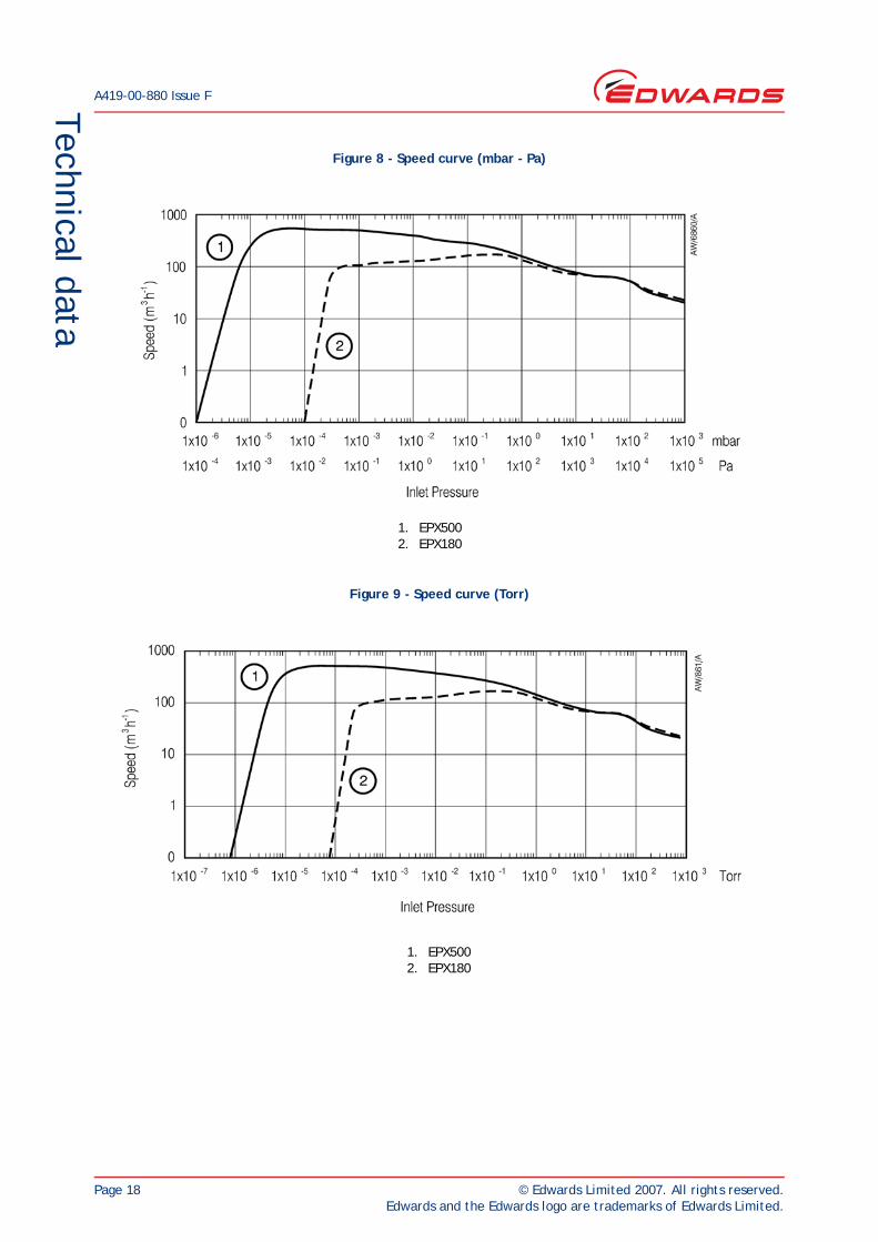
Figure 8 - Speed curve (mbar - Pa)
Figure 9 - Speed curve (Torr)
1. EPX5002. EPX180
1. EPX5002. EPX180

© Edwards Limited 2007. All rights reserved. Page 19Edwards and the Edwards logo are trademarks of Edwards Limited.
Technical dataA419-00-880 Issue F
Steady state speed curves showing the performance difference between the standard EPX ‘L’ and EPX TWIN ‘L’ variant.
Figure 10 - Speed curve (mbar - Pa) EPX and EPX Twin
Figure 11 - Speed curve (Torr) EPX and EPX Twin
1. EPX 1802. EPX TWIN 180
1. EPX 1802. EPX TWIN 180

A419-00-880 Issue F
Page 20 © Edwards Limited 2007. All rights reserved.Edwards and the Edwards logo are trademarks of Edwards Limited.
Technical data
Figure 12 - EPX L installation dimensions (EPX500L shown)
H = 388 (EPX180)H = 397 (EPX500)

© Edwards Limited 2007. All rights reserved. Page 21Edwards and the Edwards logo are trademarks of Edwards Limited.
Technical dataA419-00-880 Issue F
Figure 13 - EPX LE installation dimensions (EPX500LE shown)

A419-00-880 Issue F
Page 22 © Edwards Limited 2007. All rights reserved.Edwards and the Edwards logo are trademarks of Edwards Limited.
Technical data
Figure 14 - EPX N installation dimensions (EPX500N shown)

© Edwards Limited 2007. All rights reserved. Page 23Edwards and the Edwards logo are trademarks of Edwards Limited.
Technical dataA419-00-880 Issue F
Figure 15 - EPX NE installation dimensions (EPX500NE shown)

A419-00-880 Issue F
Page 24 © Edwards Limited 2007. All rights reserved.Edwards and the Edwards logo are trademarks of Edwards Limited.
Technical data
Figure 16 - Location of the pump centre of gravity from centre of the top of the inlet flange
Pump X’Axis Y’Axis Z’AxisEPX500L 2.23 -3.08 -202.69EPX500LE 2.21 -1.38 -203.22EPX500N -0.69 -13.91 -205.89EPX500NE -0.69 -12.24 -206.36EPX180L 2.50 -3.15 -196.39EPX180LE 2.47 -1.42 -196.90EPX180N -0.51 -14.20 -199.47EPX180NE -0.51 -12.49 -199.93

© Edwards Limited 2007. All rights reserved. Page 25Edwards and the Edwards logo are trademarks of Edwards Limited.
Technical dataA419-00-880 Issue F
Figure 17 - Gas module schematic
1. Supply port2. Solenoid valve3. Fixed pressure regulator4. Check valve5. Flow switch6. Fixed flow restrictors
7. Gas ballast port7a. Alternative ballast port (unused)8. Seal purge port8a. Alternative seal purge port (unused)9. Connector

A419-00-880 Issue F
Page 26 © Edwards Limited 2007. All rights reserved.Edwards and the Edwards logo are trademarks of Edwards Limited.
This page has been intentionally left blank.

© Edwards Limited 2007. All rights reserved. Page 27Edwards and the Edwards logo are trademarks of Edwards Limited.
InstallationA419-00-880 Issue F
3 Installation3.1 Safety
CAUTIONCooling water must be provided commensurate with environmental conditions (humidity and temperature) such that the dew point is not reached.
Ensure that the EPX pump is suitable for your application. The EPX L series of pumps are designed for semiconductor loadlock or transfer pumping applications, or clean general vacuum applications. The EPX N series of pumps are designed for the light-duty applications detailed in Figure 1. Contact Edwards or your supplier if you want to use the EPX pump on any other application. Incorrect use of the EPX pump may invalidate your warranty.
Ensure that you comply with all local and national safety requirements during installation.
Ensure that the installation technician is familiar with the safety procedures which relate to the products pumped. Wear the appropriate safety-clothing when you come into contact with contaminated components. Dismantle and clean contaminated foreline components inside a fume-cupboard. The EPX pump should NOT be dismantled under any circumstances.
Vent and purge the process system before you start installation work.
Disconnect the other components in the process system from the electrical supply so that they cannot be operated accidentally.
Further details are available from the Edwards publication ‘Vacuum pump and Vacuum System Safety’, part no. P300-20-200.
3.2 Unpack and inspect
1. Use suitable lifting equipment attached to the lifting bolts (Figure 2, item 2) to move the EPX pump into a convenient position, then remove any protective packaging and covers.
2. Inspect the pump. If the pump is damaged notify your supplier and the carrier in writing within three days; state the Item Number of the EPX pump together with your order number and your supplier's invoice number. Retain all packing materials for inspection. Do not use the pump if it is damaged.
WARNING
Obey the safety instructions given below and take note of appropriate precautions. If you do not, you can cause injury to people and damage to equipment. Do not use this pump in a manner that is not specified in this manual.
WARNING
Heavy objects can cause muscle strain or back injury. Use suitable lifting equipment to move the pump. Refer to Section 2 for the pump mass.
WARNING
Ensure that M12 metric eyebolts are fitted to the EPX pump as per Figure 2, item 2 when lifting the pump. Do not handle the pump using the gas module pipework.

A419-00-880 Issue F
Page 28 © Edwards Limited 2007. All rights reserved.Edwards and the Edwards logo are trademarks of Edwards Limited.
Installation
Note: A ‘tip and tell’ indicator is fitted to the EPX pump packaging to indicate any damage or mishandling during shipment. If the indicator shows that the EPX pump has been tilted or mishandled during shipment, do not use the pump. Please contact your local Edwards representative for advice.
3. If the EPX pump is not to be used immediately, replace the packing materials. Store the EPX pump in suitable conditions as described in Section 7.
3.3 Securing the EPX pump
1. Use suitable lifting equipment attached to the lifting bolts (Figure 2, item 2) to move the EPX pump into its required operating position. When installed, the EPX pump must be level: refer to Section 2.1.
2. Fit a suitable M8 bolt, nut and washer through the exposed fixing hole in each of the vibration isolators (4 bolts in total) (Figure 2, item 7), to secure the EPX pump to the floor, or to a frame; the floor or the frame must be able to withstand a reaction torque of at least 1000 Nm (738 lbf ft), applied rotationally about the vertical axis of the pump for at least 10 ms.
Note: The weight of the pump is evenly distributed across each of the vibration isolators. The position of the centre of gravity is given in Figure 16.
3.4 Connect the inlet to your process system
WARNING
Heavy objects can cause muscle strain or back injury. Use suitable lifting equipment to move the pump. Refer to Section 2 for the pump mass.
WARNING
For safety reasons you must make sure that any frame you mount the pump on is securely fixed to the building structure or the assembly complies with clause 7.3 (stability) of EN61010-1. Secure the EPX pump in its operating location. If you do not and the pump fails during operation, movement of the pump may damage equipment and injure people.
WARNING
In operation the surfaces on the top half of the pump can exceed 65°C; in certain fault conditions these surfaces can exceed 105°C. If the pump is to be installed in a location where the surfaces of the pump could be touched easily then the pump should be installed with adequate guarding.
WARNING
Install the pump in the vacuum system before you connect the pump to the electrical supply. If you do not, the pump may operate during installation and cause injury to people and damage to the surrounding equipment.
WARNING
Do not remove the Inlet screen from the pump. Do not operate the pump with the Inlet exposed.
WARNING
You must be able to isolate the pump from the atmosphere and from your process system if you have pumped or produced dangerous substances.
© Edwards Limited 2007. All rights reserved. Page 29Edwards and the Edwards logo are trademarks of Edwards Limited.
InstallationA419-00-880 Issue F
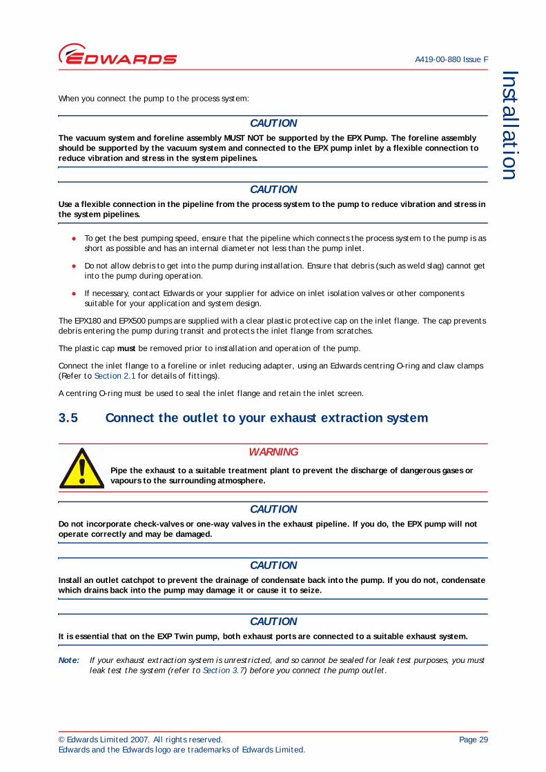
When you connect the pump to the process system:
CAUTIONThe vacuum system and foreline assembly MUST NOT be supported by the EPX Pump. The foreline assembly should be supported by the vacuum system and connected to the EPX pump inlet by a flexible connection to reduce vibration and stress in the system pipelines.
CAUTIONUse a flexible connection in the pipeline from the process system to the pump to reduce vibration and stress in the system pipelines.
To get the best pumping speed, ensure that the pipeline which connects the process system to the pump is as short as possible and has an internal diameter not less than the pump inlet.
Do not allow debris to get into the pump during installation. Ensure that debris (such as weld slag) cannot get into the pump during operation.
If necessary, contact Edwards or your supplier for advice on inlet isolation valves or other components suitable for your application and system design.
The EPX180 and EPX500 pumps are supplied with a clear plastic protective cap on the inlet flange. The cap prevents debris entering the pump during transit and protects the inlet flange from scratches.
The plastic cap must be removed prior to installation and operation of the pump.
Connect the inlet flange to a foreline or inlet reducing adapter, using an Edwards centring O-ring and claw clamps (Refer to Section 2.1 for details of fittings).
A centring O-ring must be used to seal the inlet flange and retain the inlet screen.
3.5 Connect the outlet to your exhaust extraction system
CAUTIONDo not incorporate check-valves or one-way valves in the exhaust pipeline. If you do, the EPX pump will not operate correctly and may be damaged.
CAUTIONInstall an outlet catchpot to prevent the drainage of condensate back into the pump. If you do not, condensate which drains back into the pump may damage it or cause it to seize.
CAUTIONIt is essential that on the EXP Twin pump, both exhaust ports are connected to a suitable exhaust system.
Note: If your exhaust extraction system is unrestricted, and so cannot be sealed for leak test purposes, you must leak test the system (refer to Section 3.7) before you connect the pump outlet.
WARNING
Pipe the exhaust to a suitable treatment plant to prevent the discharge of dangerous gases or vapours to the surrounding atmosphere.

A419-00-880 Issue F
Page 30 © Edwards Limited 2007. All rights reserved.Edwards and the Edwards logo are trademarks of Edwards Limited.
Installation
Remove the blanking plugs from the outlet(s) (Figure 2, item 8 [there are two outlets on the EPX Twin]), use a suitable clamp and seals to connect the outlet(s) to your exhaust pipeline. Take note of the following when you connect the exhaust pipeline:
If your exhaust pipeline incorporates any shut-off valves, you must be able to prevent operation of the pump when any of the valves are closed (that is, the pipeline is restricted or blocked). If the EPX (Twin) pump operates when the pipeline is restricted or blocked, the pump will not operate correctly and may be severely damaged.
You should not incorporate a check valve in the exhaust line of the EPX (Twin) pump. If you do, the EPX (Twin) pump may not operate properly and may become damaged. If an exhaust check valve is unavoidable then you must ensure that the pump is at atmospheric pressure (for example by use of a foreline purge) before you start the pump. This applies to all EPX (Twin) pump variants.
Incorporate flexible bellows in the exhaust pipeline to reduce the transmission of vibration and to prevent the loading of coupling-joints. If you use flexible bellows, you must ensure that you use bellows which have a maximum pressure rating which is greater than the highest pressure that can be generated in your system, and which can withstand the maximum temperatures that can be generated by your process conditions, for example, braided flexible bellows may be used for this purpose.
The exhaust pipeline must be a minimum diameter of NW25 throughout.
3.6 Nitrogen purge (EPX N series pumps)
The following instructions apply to EPX N series pumps. They are not applicable to EPX L series pumps.
A 1/4 inch compression fitting is provided on the pump, marked ‘N2 Inlet’. Connect the nitrogen purge supply to the nitrogen purge inlet connection using 1/4 inch OD tube, (refer to Figure 6, item 4).
Ensure that the nitrogen supply is stable to guarantee that the nitrogen purge flow is maintained. The nitrogen purge gas should comply with the specifications detailed in Table 10.
WARNING
The EPX pump should not be used to pump pyrophoric gases or explosive mixtures.
WARNING
Dilute flammable gases to less than 25% of the LEL (Lower Explosive Limit) before the pump inlet. The responsibility for ensuring the correct dilution of the pumped gas lies with the operator.
WARNING
The flow switch is set to 12 slm and therefore provides an indication that a flow in excess of 12 slm is present, but gives no guarantee that there is sufficient flow to prevent condensation or to provide sufficient dilution of the process gas to safe levels.
WARNING
The flow switch is not a guaranteed interlock. To ensure dilution of the process gas to safe levels, the system installer must fit appropriate interlocked hardware to ensure correct nitrogen purge flow and monitoring.

© Edwards Limited 2007. All rights reserved. Page 31Edwards and the Edwards logo are trademarks of Edwards Limited.
InstallationA419-00-880 Issue F
3.7 Leak test the system
Note: If your exhaust extraction system is unrestricted, and so cannot be sealed for leak test purposes, you must leak test the system before you connect to the pump outlet.
Leak test the system, then seal any leaks found. Substances which leak from the system may be dangerous to people, and there may be a danger of explosion if air leaks into the system.
As supplied, the leak rate of the EPX pump is tested to be less than 1 x 10⁻⁵ mbar l s-1 (1 x 10⁻³ Pa l s-1, 2.1 x 10⁻⁸ atm ft3 min-1). The required leak rate for your system will depend on your safety and process requirements.
3.8 Connect the cooling-water supply
CAUTIONDo not operate the pump without connecting the water supply and return lines, as permanent damage may be caused to the equipment.
CAUTIONAppropriate filtration must be provided to ensure that the water supply quality is in accordance with Table 9.
CAUTIONCooling water must be provided commensurate with environmental conditions (humidity and temperature) such that the dew point is not reached.
CAUTIONTo prevent damage to the pump in the event of cooling-water supply failure or a blockage in the pump, we recommend that you incorporate a suitable flow-switch in the cooling-water return pipelines. You can connect the outputs of the flow-switch to your control equipment to shut down the pump if the cooling-water flow through the pump gets too low.
WARNING
Leak test the system and seal any leaks found to prevent the leakage of dangerous substances out of the system and leakage of air into the system.
WARNING
In products supplied with quick-release water connectors, a water expansion valve is installed between the connector and the pump. This is to prevent over-pressurisation of the water circuit in the event that the pump is incorrectly operated with water supply disconnected. When using or maintaining this pump DO NOT REMOVE THE WATER EXPANSION VALVE.
WARNING
A release of water under pressure constitutes a significant safety hazard. The water supply should be provided with an isolator in accordance with SEMI S2-0200 Lockout/Tagout requirements.
A419-00-880 Issue F
Page 32 © Edwards Limited 2007. All rights reserved.Edwards and the Edwards logo are trademarks of Edwards Limited.
Installation
Connect the cooling-water supply as follows:
1. If the pump has been supplied with quick-release connectors, fit a suitable female quick-release connector to your cooling water supply line, and a suitable male quick-release connector to your cooling water return line (refer to Section 2).
2. Refer to Figure 2. Remove the yellow blanking-caps from the cooling-water inlet (Figure 2, item 4) and outlet (Figure 2, item 9).
3. Fit the male quick-release connector on your cooling-water return pipeline to the cooling-water outlet (Figure 2, item 9).
4. Fit the female quick-release connector on your cooling-water supply pipeline to the cooling-water inlet (Figure 2, item 4).
5. Turn on the cooling water supply.
6. Inspect the water hoses, pipelines and connection to make sure that there are no leaks.
7. Turn off the water supply whilst the remainder of the installation procedure is completed.
Take note of the following when you connect the cooling-water supply and return pipelines:
Route and secure cables, hoses and pipe-work neatly during installation to avoid possible risk of trips.
Wipe up any water spilt during installation to avoid possible risk of slips.
Each EPX pump must be connected to an independent water circuit not in series with each other or other equipment.
The cooling-water supply should have a lock out/tagout facility in accordance with SEMI S2-0200 clause 17.4.
We recommend that you incorporate a suitable ball-type flow indicator in your water return pipeline, to provide a visual indication of cooling water flow through the EPX pump.
We recommend that you incorporate a suitable filter in the water supply pipeline, if the water supply contains particulates. (For the cooling-water supply specification refer to Section 2.4).
To conserve resources we recommend that the return water is cooled and re-circulated.
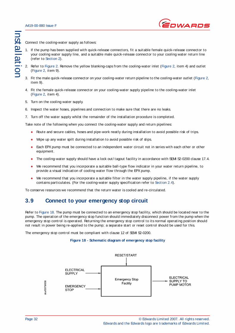
3.9 Connect to your emergency stop circuit
Refer to Figure 18. The pump must be connected to an emergency stop facility, which should be located near to the pump. The operation of the emergency stop function should immediately disconnect power from the pump when the emergency stop control is operated. Returning the emergency stop control to its normal operating position should not result in power being re-applied to the pump; a separate start or reset control should be used for this.
The emergency stop control must be compliant with clause 12 of SEMI S2-0200.
Figure 18 - Schematic diagram of emergency stop facility

© Edwards Limited 2007. All rights reserved. Page 33Edwards and the Edwards logo are trademarks of Edwards Limited.
InstallationA419-00-880 Issue F
3.10 Connect the EPX pump to the electrical supply
Use the following procedure to connect the EPX pump to the electrical supply:
1. Use a suitable earth (ground) cable to connect the M8 protective earth (ground) stud (Figure 2, item 3) on the EPX pump to a suitable earth (ground) point: refer to Section 2.3 for the cable rating.
2. If an electrical supply plug is not fitted:
Connect the four core electrical supply cable to earth (green/yellow) and three phases (1, 2, 3 respectively) by direct connection to a suitable control box with a means of isolation, and by means of a suitably IP rated four pin connector.
Notes: 1. If you connect the electrical supply to the EPX pump through ELCB relays, they must be suitable for the protection of equipment with a d.c. component in the fault current, and suitable for short-duration switch-on surges, and for high leakage currents (for example, type B, according to prEN50178).
2. If you have a plug to connect the EPX pump to your mains disconnect device, you must provide Lockout/Tagout in conformance with the requirements of SEMI S2-0200 Section 17.
The mains disconnect device should conform with all the following statements:
The mains disconnect device must be provided by the user and should be in a location satisfying the requirements of SEMI S8 where it is readily accessible.
The mains disconnect device should not be located where there is any risk of personnel tripping on cables, being obstructed or exposed to other hazards.
The mains disconnect device should be marked as a disconnection device.
The mains disconnect device must be connected between the source of supply and the main power cable entering the EPX pump.
The mains disconnect device must have a lockout/tagout facility of the type specified in Section 17 of SEMI S2-0200.
The mains disconnect device must be rated at a minimum of 10,000 AIC.
WARNING
Connect the electrical supply to the EPX pump through a suitable fuse/ isolator rated as specified in Section 2.3.
WARNING
Do not operate the EPX pump unless it is correctly earthed (grounded) using the protective earth stud (Figure 2, item 3).
WARNING
Ensure that the electrical supply and connectors are rated for the voltage of the pump as marked on the rating label attached to the mains inlet cover.
WARNING
There are no user serviceable parts within the EPX pump. Metal covers must not be removed from the pump; to do so may cause damage to the pump and injury to personnel and would invalidate the declaration of conformity and the warranty. Qualified Edwards service personnel should allow 4 minutes after the isolation of power before removing any covers.

A419-00-880 Issue F
Page 34 © Edwards Limited 2007. All rights reserved.Edwards and the Edwards logo are trademarks of Edwards Limited.
Installation
3.11 Connect to your control equipment
CAUTIONDo not connect voltages greater than 30 V to the EPX interface control. If you do, the interface control will not comply with the low voltage safety directive and the equipment may be damaged.
The pump may be connected to your control equipment through the Tool Interface connector (TIM). The TIM is supplied with a protective plastic cap fitted. Remove this before connecting the mating connector. Several different tool interfaces are available. The label next to the tool connector identifies which TIM is fitted, refer to Table 12 to identify the tool connectors and mating tool connector kits available (not supplied with the pump).
Note: Plug/Socket designation refers to the pins of the connector.
3.11.1 Inputs
Refer to Table 13 for a definition of the input signals to the pump system.
Notes: 1. Volt free contacts sensed at 24 V / 5 mA, these inputs should not be linked together.
2. Voltage inputs accept AC or DC voltage (except SPI pins 15 and 16), between 15 V and 24 V selects the input as active, below 5 V selects inactive.
3. To ensure correct pump operation, at least 10 seconds must be allowed between successive operations of the input signals.
WARNING
Tool interface control signals are for control purposes only and should not be relied upon for safety critical functions.
Table 12 - Tool connectors and mating tool connector kits
Identification Part Number Tool Side Connector Tool Connector Kit
SPI D373-60-310 CPC 16/17 Socket D374-20-801
MCM D373-60-320 CPC 16/17 Socket D374-22-802
TEL D373-60-330 25w D Type Socket D374-20-802
E73 D373-60-340 15w D Type Plug D374-20-803
LAM D373-60-350 25w D Type Plug D374-22-801
C3 D373-60-360 9w D Type Socket D374-21-803
HIT D373-60-370 37w D Type Socket D374-21-804
Table 13 - Tool input signals to the pump system
Function Signal Type Pins Operation
Pump On/Off Voltage input SPI - 1 and 2MCM - 1 and 2LAM - 10 and 23C3 - 2 and 6
Pump runs when voltage applied
Volt-free contact input MCM - 5 and 6TEL - 1 and 14E73 - 1 and 9HIT - 7 and 26(or HIT - 1 and 20)
Pump runs when contact closed

© Edwards Limited 2007. All rights reserved. Page 35Edwards and the Edwards logo are trademarks of Edwards Limited.
InstallationA419-00-880 Issue F
3.11.2 Outputs
Table 14 defines the Output signals from the pump system, all signals are volt free contacts.
Notes: 1. Volt free contacts are rated at 24 V, 1 A.
2. All pump status outputs are maintained through a power loss of up to 1 second.
3. All status contacts open if power is removed.
Table 14 - Output signals from the pump system
Function Pins Operation
Pump running SPI - 3 and 4MCM - 3 and 4TEL - 8 and 20E73 - 3 and 11LAM - 2 and 15C3 - 5 and 9HIT - 19 and 37HIT - 12 and 30
Closed when pump running
Warning SPI - 7 and 8MCM - 7 and 8TEL - 9 and 21E73 - 5 and 13C3 - 4 and 8HIT - 14 and 32
Closed at all times (no warnings are available on the EPX pump).
Alarm SPI - 9 and 10MCM - 9 and 10TEL - 10 and 22E73 - 6 and 14LAM - 1 and 14C3 - 3 and 7HIT - 15 and 33
Closed when no alarm condition exists on the drive inverter. See Section 4.3 and 4.4 for more information.
Gas flow warning SPI - 11 and 12MCM - 11 and 12TEL - 11 and 23LAM - 3 and 16HIT - 16 and 34
Closed when gas purge flow warning does not exist (closed if no gas module is present).
Pump status/Final Valve SPI - 13 and 14 Closed when pump running and gas purge flow warning does not exist
Remote/Local control status E73 - 7 and 15 Closed when remote control is available through the tool interface.

A419-00-880 Issue F
Page 36 © Edwards Limited 2007. All rights reserved.Edwards and the Edwards logo are trademarks of Edwards Limited.
This page has been intentionally left blank.

© Edwards Limited 2007. All rights reserved. Page 37Edwards and the Edwards logo are trademarks of Edwards Limited.
End User Controller (EU
C) and Pump D
isplay Terminal (PD
T) menus
A419-00-880 Issue F
4 End User Controller (EUC) and Pump Display Terminal (PDT) menus
4.1 Introduction
The display and the control buttons used on both the EUC and the PDT are shown in Figure 7.
The menu structure is shown in Table 15. Note that if a particular system component or accessory is not fitted, the corresponding menu option is shown as ‘NP’ (not present).
Menus used and the display messages shown on the EUC and PDT are described in the menu diagrams in Figure 19 to 28. The following symbols and conventions are used in the menu diagrams:
These are flow lines. Arrows on the lines show the direction of flow through a menu.
This symbol is used to connect different menus and shows the starting point (or continuation point) of a menu.
This symbol is used for the ENTER and CANCEL buttons and the four menu buttons: Normal, Status, Control and Setup.
This symbol is used for the up (▲) and down (▼) buttons and for the on ( ) and off ( ) buttons.
This symbol is used for the two-line display on the PDT.
This symbol is a submenu box; a submenu is a series of menu steps which are used in a number of different menus or used in different parts of one menu. Completion of the menu returns to the previous menu.
This symbol shows additional text which is not part of the menu, but which further describes the operation of the menu.
<Name>

A419-00-880 Issue F
Page 38 © Edwards Limited 2007. All rights reserved.Edwards and the Edwards logo are trademarks of Edwards Limited.
End User Controller (EU
C) and Pump D
isplay Terminal (PD
T) menus
4.2 General operation
When you first switch on the EPX system, the Normal display is shown: refer to Figure 22. You can then press the On or Off button, or any of the four menu buttons to exit the current menu and enter the corresponding new menu. Figure 19 shows this menu control logic.
Note that if a warning or alarm is displayed, the orange or red LED will flash until the warning or alarm is acknowledged by pressing the <ENTER> button. Once acknowledged the LED will remain continuously lit. If a gas flow warning is generated by low flow and then the gas flow is restored, the orange warning LED will flash until the warning is acknowledged and will then go out.
4.3 The CANCEL button
You can press the CANCEL button at any time during menu operation. For this reason, we have not shown the use of the CANCEL button on all of the menu diagrams, but we have shown specific uses where there is no other obvious way to cancel the current menu option and enter the previous menu option. In general, when you press the CANCEL button, the current menu option is cancelled and the previous menu option is displayed. Other specific uses of the CANCEL button are as follows:
In the Switch On and Switch Off menus (Figure 20 and 21), when you press CANCEL, the menu is exited and the display reverts to that which was displayed before On or Off were pressed.
In the Status menu (Figure 23), when you press CANCEL the display shows the first two status parameters (the defaults are EPX current consumption and power consumption).
When you enter the password for the setup menu (Figure 25), if you press CANCEL, before you enter the value, the menu moves back to entry of the previous digit of the password.
4.4 Display text and variable text
In the menu diagrams in Figure 19 to 28, text shown without chevron brackets in the two-line display symbol is the actual text that will be shown on the display. In this text, the 'Δ' symbol is used to show where a digit will be shown; the value of the digit depends on the sensor data or information you enter into the system.
Text enclosed in chevron brackets (for example, <status>) defines variable text; what is shown on the display depends on the menu or the EPX system and data entered by the user. The following variable text markers are used on the menu diagrams:
<status>
Text message giving status of the selected parameter.
<serial number>
This specifies the serial number. The serial number is a number which you can use to identify the EPX system in the installation.
<parameter>
This is a previously selected parameter or menu option.
<message>
This specifies a warning, alarm or advisory message.

© Edwards Limited 2007. All rights reserved. Page 39Edwards and the Edwards logo are trademarks of Edwards Limited.
End User Controller (EU
C) and Pump D
isplay Terminal (PD
T) menus
A419-00-880 Issue F
4.5 Wrap-around
When you use the up and down buttons to change a digit or character on the display, the digit or character will 'wrap-around' between its minimum and maximum values. For example, when you enter a password digit, if the digit is '0' and you press the down button, the digit will change to '9'; if the digit is '9' and you press the up button, the digit will change to '0'.
4.6 Timeout
After you have entered a menu (other than the Normal menu), if you do not press a button for five minutes, the EUC or PDT will automatically exit the current menu and enter the Normal menu. This facility (known as timeout) is available so that if the setup menu is entered and then EPX system is accidentally left unattended, the menu is exited to prevent unauthorized use of the menu options.
4.7 Menu structure
The display and the control buttons are shown in Figure 7.
The menu structure is shown in Table 15. Note that if a particular system component or accessory is not fitted, the corresponding menu option is shown as 'NP' (not present).
Table 15 - EUC and PDT menu structure
Menu Figure
PDT menu logic 19
Switch on 20
Switch off 21
Normal (default) Menu 22
Status Menu 23
Control Menu 24
Setup Menu 25
Software Version 26
Select Units Menu 27
Select Line Menu 28
Service Menu Service Personnel only
Serial Number Service Personnel only
Time/Date Service Personnel only
A419-00-880 Issue F
Page 40 © Edwards Limited 2007. All rights reserved.Edwards and the Edwards logo are trademarks of Edwards Limited.
End User Controller (EU
C) and Pump D
isplay Terminal (PD
T) menus
4.8 Example
Here is an example of how to interpret the menu diagrams. The following procedure describes how to change the parameters displayed on the normal display.
1. Press the Setup button to enter the Setup menu (Figure 25).
2. Use the up and down buttons to change the first digit of the setup password to the correct value, then press the ENTER button.
3. Use the up and down buttons to change the second digit of the setup password to the correct value, then press the ENTER button.
4. Use the up and down buttons to change the third digit of the setup password to the correct value, then press the ENTER button.
5. If you have entered the correct password, the display will then show 'SETUP MENU' on the top line and the software version on the bottom line. (Figure 26).
6. Press the down button or the up button twice; the display will then show 'SETUP MENU' on the top line and Normal display on the bottom line.
7. Press the ENTER button; the display will then show 'SELECT LINE' on the top line and ‘Top Page 1’ on the bottom line (refer to Figure 28).
8. Press the ENTER button; the display will then show 'SELECT PARAMETER' on the top line and the currently selected parameter on the bottom line.
9. Press the up or down buttons to change the parameter displayed to the required parameter, then press the ENTER button. The top line of the Normal Display will now display the parameter that was selected.

© Edwards Limited 2007. All rights reserved. Page 41Edwards and the Edwards logo are trademarks of Edwards Limited.
End User Controller (EU
C) and Pump D
isplay Terminal (PD
T) menus
A419-00-880 Issue F
Figure 19 - EUC and PDT menu logic

A419-00-880 Issue F
Page 42 © Edwards Limited 2007. All rights reserved.Edwards and the Edwards logo are trademarks of Edwards Limited.
End User Controller (EU
C) and Pump D
isplay Terminal (PD
T) menus
Figure 20 - Switch on menu
Figure 21 - Switch off menu
© Edwards Limited 2007. All rights reserved. Page 43Edwards and the Edwards logo are trademarks of Edwards Limited.
End User Controller (EU
C) and Pump D
isplay Terminal (PD
T) menus
A419-00-880 Issue F
Figure 22 - Normal menu

A419-00-880 Issue F
Page 44 © Edwards Limited 2007. All rights reserved.Edwards and the Edwards logo are trademarks of Edwards Limited.
End User Controller (EU
C) and Pump D
isplay Terminal (PD
T) menus
Figure 23 - Status menu

© Edwards Limited 2007. All rights reserved. Page 45Edwards and the Edwards logo are trademarks of Edwards Limited.
End User Controller (EU
C) and Pump D
isplay Terminal (PD
T) menus
A419-00-880 Issue F
Figure 24 - Control menu

A419-00-880 Issue F
Page 46 © Edwards Limited 2007. All rights reserved.Edwards and the Edwards logo are trademarks of Edwards Limited.
End User Controller (EU
C) and Pump D
isplay Terminal (PD
T) menus
Figure 25 - Setup menu (sheet 1 of 2)

© Edwards Limited 2007. All rights reserved. Page 47Edwards and the Edwards logo are trademarks of Edwards Limited.
End User Controller (EU
C) and Pump D
isplay Terminal (PD
T) menus
A419-00-880 Issue F
Figure 25 - Setup menu (sheet 2 of 2)

A419-00-880 Issue F
Page 48 © Edwards Limited 2007. All rights reserved.Edwards and the Edwards logo are trademarks of Edwards Limited.
End User Controller (EU
C) and Pump D
isplay Terminal (PD
T) menus
Figure 26 - Software version

© Edwards Limited 2007. All rights reserved. Page 49Edwards and the Edwards logo are trademarks of Edwards Limited.
End User Controller (EU
C) and Pump D
isplay Terminal (PD
T) menus
A419-00-880 Issue F
Figure 27 - Select units menu

A419-00-880 Issue F
Page 50 © Edwards Limited 2007. All rights reserved.Edwards and the Edwards logo are trademarks of Edwards Limited.
End User Controller (EU
C) and Pump D
isplay Terminal (PD
T) menus
Figure 28 - Select line menu
© Edwards Limited 2007. All rights reserved. Page 51Edwards and the Edwards logo are trademarks of Edwards Limited.
Operation
A419-00-880 Issue F
5 Operation5.1 Introduction
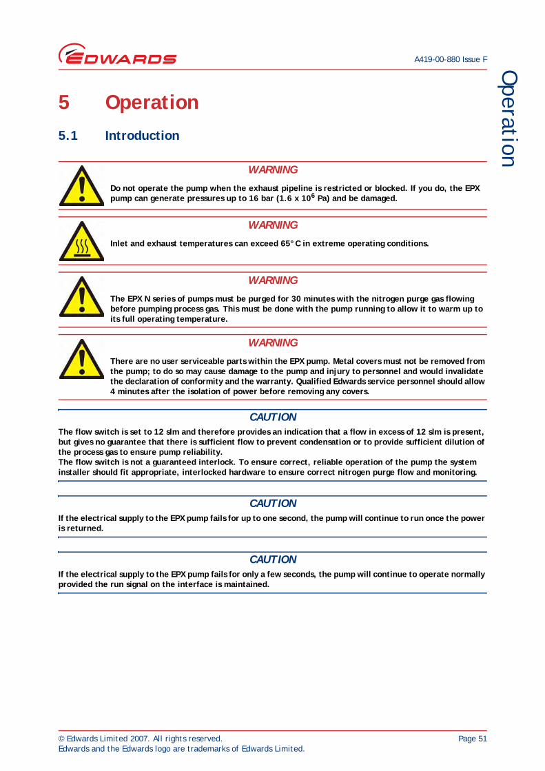
CAUTIONThe flow switch is set to 12 slm and therefore provides an indication that a flow in excess of 12 slm is present, but gives no guarantee that there is sufficient flow to prevent condensation or to provide sufficient dilution of the process gas to ensure pump reliability.The flow switch is not a guaranteed interlock. To ensure correct, reliable operation of the pump the system installer should fit appropriate, interlocked hardware to ensure correct nitrogen purge flow and monitoring.
CAUTIONIf the electrical supply to the EPX pump fails for up to one second, the pump will continue to run once the power is returned.
CAUTIONIf the electrical supply to the EPX pump fails for only a few seconds, the pump will continue to operate normally provided the run signal on the interface is maintained.
WARNING
Do not operate the pump when the exhaust pipeline is restricted or blocked. If you do, the EPX pump can generate pressures up to 16 bar (1.6 x 10⁶ Pa) and be damaged.
WARNING
Inlet and exhaust temperatures can exceed 65°C in extreme operating conditions.
WARNING
The EPX N series of pumps must be purged for 30 minutes with the nitrogen purge gas flowing before pumping process gas. This must be done with the pump running to allow it to warm up to its full operating temperature.
WARNING
There are no user serviceable parts within the EPX pump. Metal covers must not be removed from the pump; to do so may cause damage to the pump and injury to personnel and would invalidate the declaration of conformity and the warranty. Qualified Edwards service personnel should allow 4 minutes after the isolation of power before removing any covers.

A419-00-880 Issue F
Page 52 © Edwards Limited 2007. All rights reserved.Edwards and the Edwards logo are trademarks of Edwards Limited.
Operation
5.2 Flammable and toxic gases (EPX N series pumps)
The nitrogen purge flows on the EPX N series of pumps are preset at the factory.
The approximate nitrogen purge flows for a given supply pressure are given in Table 10.
Flammable gases must be diluted to less than 25% of the LEL. Pyrophoric gases and explosive mixtures should not be pumped using the EPX pump. The installer must ensure that suitable safety mechanisms are in place to ensure that dilution is carried out to safe levels.
5.3 Start-up
1. Check the protective earth connection to the pump.
2. Check that the power and control connectors from the pump are connected.
3. Switch on the cooling-water supply and check that there are no leaks. If there are any leaks, switch off the cooling-water supply, seal the leaks, then switch on the cooling-water supply and check for leaks again. Repeat this process until the system is leak-tight.
4. Switch on the electrical supply to the EPX pump, and check that the Power LED (Figure 4, item 2) goes on; if the Power LED does not go on, refer to Section 6.6.
5. Check that the exhaust-extraction system is not restricted, and that any valves in the exhaust-extraction system are open.
6. Use your control equipment to set the pump run signal to the interface connector (refer to Section 3.11) and check that the Run LED (Figure 4, item 3) goes on, and that the pump running status output closes. If the Run LED does not go on, or if the pump running status output remains open, refer to Section 6.6.
WARNING
The EPX pump should not be used to pump pyrophoric gases or explosive mixtures.
WARNING
Dilute flammable gases to less than 25% of the LEL (lower explosive limit) before the pump inlet. The responsibility for ensuring the correct dilution of the pumped gas lies with the operator.
WARNING
For flammable and toxic gases, the EPX pump must be fitted in an extracted enclosure (not supplied), and the extract must be monitored. In order for the pump to comply with Semi S2-0200 extracted enclosures are required.
WARNING
Do not operate the pump when the exhaust pipeline is restricted or blocked. If you do, the EPX pump can generate pressures up to 16 bar (1.6 x 10⁶ Pa) and be damaged.

© Edwards Limited 2007. All rights reserved. Page 53Edwards and the Edwards logo are trademarks of Edwards Limited.
Operation
A419-00-880 Issue F
5.4 Manual shut-down
CAUTIONThe pump can take up to three minutes to completely stop.
CAUTIONEPX N pumps must be purged for 30 minutes with nitrogen before the run signal is removed.
Use the following procedure to shut down the pump.
Use your control equipment to remove the run signal to the pump (refer to Section 3.11). The Run LED (Figure 4, item 3) will then go off, and the pump running status output signal will open.
Note: After removing the run signal, the pump should be allowed to come to a stop before the run signal is re-applied. If the run signal is removed for more than 1 second and then re-applied before the pump has stopped, the pump will run down to a stop before restarting automatically. This is a function of the control architecture of the pump.
If you are removing the pump, follow the instructions given in Section 7.
5.5 Status and fault indications
During normal operation, only the Power and Run LEDs (Figure 4, items 2 and 3) should be on, and the pump running, pump warning and pump alarm status outputs should be closed. If either or both of the other LEDs (Figure 4, items 4 and 5) go on, or if either or both of the pump warning and pump alarm status output signals are open, refer to Section 6.6.
5.6 Unplanned shutdown and alarms
The EPX will automatically shutdown when a pump protection sensor operates (refer to Section 1.3), or should the inverter drive fail. When the EPX automatically shuts down, the Alarm LED (Figure 4, item 5) is illuminated, and the pump alarm status output signal opens.
If the EPX pump goes into an Alarm state, power to the pump must be completely switched off and then re-applied in order for the alarm to clear. The pump fault must be identified and rectified before power is re-applied.
If there is an unplanned shutdown, ensure that the cause of the shutdown is identified and rectified before the pump is restarted. If you are in doubt, please call a Edwards representative.
WARNING
Do not remove the inlet connection until the pump has been allowed to stop rotating and the power has been isolated.
WARNING
In the event of an unplanned shutdown the pump should not be restarted unless the cause is identified and rectified. If this is not the case, seal the inlet and exhaust of the pump and call a Edwards representative.

A419-00-880 Issue F
Page 54 © Edwards Limited 2007. All rights reserved.Edwards and the Edwards logo are trademarks of Edwards Limited.
This page has been intentionally left blank.

© Edwards Limited 2007. All rights reserved. Page 55Edwards and the Edwards logo are trademarks of Edwards Limited.
Maintenance
A419-00-880 Issue F
6 Maintenance
Purge the pump for 1/2 an hour with nitrogen before removing the power.
There are no user serviceable parts in the EPX pump mechanism, electric motor or electrical controls. Attempting to remove the pump rotor, separate the motor from the pump or remove electrical covers can cause injury to people or damage to equipment.
It is recommended that all maintenance and service operations are carried out by qualified Edwards Service Personnel, excepting:
Connection and inspection of pipelines and connections to foreline and exhaust. Routine external cleaning. Connection and disconnection to electrical power. Connection and disconnection of electrical signals.
WARNING
There are no user serviceable parts within the EPX. There is no requirement to remove the covers from the pump during normal operation. Removing the covers could cause injury to people or damage to equipment.
WARNING
Toxic, flammable and corrosive chemicals may be present within the pump enclosure. Ensure that the appropriate Personal Protective Equipment (PPE) is worn when carrying out any maintenance tasks.
WARNING
Before disconnecting EPX N pumps from the system, purge the pump for 30 minutes, then lockout/tagout the nitrogen supply.
WARNING
There are no user serviceable parts within the EPX pump. Metal covers must not be removed from the pump; to do so may cause damage to the pump and injury to personnel and would invalidate the declaration of conformity and the warranty. Qualified Edwards service personnel should allow 4 minutes after the isolation of power before removing any covers.

A419-00-880 Issue F
Page 56 © Edwards Limited 2007. All rights reserved.Edwards and the Edwards logo are trademarks of Edwards Limited.
Maintenance
6.1 Safety
CAUTIONIn the event of a pump seizure, dust is generated as a result of contact between the rotating and static surfaces. This dust may contain aluminium sulphate in low concentrations and may be accompanied by a slightly sulphurous smell.
It is recommended that when dealing with a pump which may have seized you wear gloves, eye protection and a paper face mask.
Allow the EPX pump to cool to ambient temperature before you start maintenance work.
Wipe up any spilt water during maintenance so as to avoid possible risk of slips.
Isolate the EPX pump and other components in the process system from the electrical supply so that they cannot be operated accidentally.
Lockout/Tagout the nitrogen supply and water supply.
Do not reuse O-rings.
Protect sealing-faces from damage.
If you need to remove the pump, follow the instructions given in Section 7.1.
If you disconnect the inlet from the process system, leak-test the system after maintenance work is complete and seal any leaks found to prevent leakage of dangerous substances out of the system and leakage of air into the system: refer to Section 3.7.
The inverter drive contains capacitors which store electrical energy after the pump has been shut down. Wait at least four minutes after the pump has been shut down before you start any work on the electrical system of the EPX pump.
The pump covers should not be removed as the pump contains sensitive electronic components. None of the components in the pump are user serviceable.
6.2 Maintenance plan
The plan shown in Table 16 details the maintenance operations we recommend to maintain the EPX pump in normal operation. Instructions for each operation are given in the section shown.
WARNING
Obey the safety instructions given below and take note of appropriate precautions. If you do not you can cause injury to people and damage to equipment.
WARNING
Do not touch or inhale the thermal breakdown products of fluorinated materials which may be present if the EPX pump has overheated to 260 ºC (500 ºF) and above. These breakdown products are very dangerous. The pump may have overheated if it was misused, if it malfunctioned, or if it was in a fire. Edwards Material Safety Data Sheets for the fluorinated materials used in the EPX pump are available on request: contact your supplier or Edwards. MSDS: Mechanical Pump Oil - Fomblin 6/6 Series P120-01-015, O-rings - Viton P120-04-015.

© Edwards Limited 2007. All rights reserved. Page 57Edwards and the Edwards logo are trademarks of Edwards Limited.
Maintenance
A419-00-880 Issue F
6.3 Inspect the pipelines and connections
1. Inspect all cooling-water pipelines and connections; check that they are not corroded or damaged. Replace any of the pipelines and connections that are corroded or damaged. Check that all cooling-water connections are secure. Tighten any connections that are loose.
2. Inspect all electrical cables; check that they are not damaged and have not overheated. Replace any cables that are damaged or have overheated. Check that all electrical connections are secure. Tighten any connections that are loose.
3. Inspect all process and exhaust pipelines; check that they are not corroded or damaged. Replace any pipelines that are corroded or damaged. Check that all process and exhaust connections are secure. Tighten any connections that are loose.
6.4 Cleaning the pump
CAUTIONDo not use cleaning materials based on strong alkalis, aggressive or chlorinated solvents.
CAUTIONDo not use cleaning materials containing abrasives.
Inspect the pump annually (or as part of any scheduled preventative maintenance schedule) and, if necessary, wipe the outside clean with a soft lint free cloth and a proprietary cleaning material based or demineralised water or isopropanol.

A419-00-880 Issue F
Page 58 © Edwards Limited 2007. All rights reserved.Edwards and the Edwards logo are trademarks of Edwards Limited.
Maintenance
6.5 Service the EPX pump
The service interval for the EPX series of dry pumps is shown in Table 16. Major service is outside the scope of this manual and must be carried out by qualified Edwards Service personnel: contact your supplier or Edwards to arrange a major service.
For removal of the pump for maintenance refer to Section 7.
Table 16 - Maintenance plan
Operation Frequency Refer to Section
Inspect the pipelines and connections Annually or as part of a preventative maintenance schedule
6.3
Cleaning the pump Annually or as part of a preventative maintenance schedule
6.4
Service the EPX L/LE pumpService the EPX N/NE pumpService the EPX TWIN pump (all variants)
Pump service requirements are largely determined by the pump’s operating environment and application. Service intervals range from 2 to 5 years*. Please contact your local Edwards service representative for further advice on a suitable maintenance schedule.
* Main factors that will affect the service intervals of the EPX pump are:
The ambient temperature in which the pump runs - Higher ambient temperatures will result in shorter service intervals (refer to Table 6 for the ambient operating temperature range)
The temperature and flow rate of the cooling water delivered to the pump - higher water temperatures and a lower flow rates will result in shorter service intervals (refer to Table 9 for cooling water supply details)
Rapidity of cycling - rapid cycling applications will result in shorter service intervals
Application - processes that require a Nitrogen purge (EPX N-series pumps) will typically result in shorter service intervals
6.5

© Edwards Limited 2007. All rights reserved. Page 59Edwards and the Edwards logo are trademarks of Edwards Limited.
Maintenance
A419-00-880 Issue F
6.6 Fault finding
Refer to Table 17 and 18 for fault finding.
Table 17 - Fault finding
Symptom Check Action
The Power LED does not illuminate when the electricity supply is switched on
Is the electrical supply correctly connected?
Ensure that the electrical supply is correctly connected to the EPX pump; refer to Section 3.9 and 3.10.
The Run LED does not illuminate, or the pump running status output signal is open, when the start signal is set
Is the EPX pump incorrectly connected to your control equipment?
Ensure that the connections between your control equipment and the interface connector are correct: refer to Section 3.11
The pump alarm status output signal is open and the Alarm LED is off
Is the pump incorrectly connected to your control equipment?
Ensure that the connections between your control equipment and the interface connector are correct to Section 3.11.
The pump alarm status output signal is open and the Alarm LED is illuminated
Has the cooling water supply failed? Allow the EPX pump to cool down for at least 20 minutes. Ensure that the cooling water supply is correctly connected to the EPX pump, and is switched on and meets the flow and pressure requirements of Section 2.4. Restart the pump.
A whistling sound is heard as the pump decelerates
Has the run signal been removed and then re-applied before the pump has stopped?
Removal and re-application of the run signal may cause a low volume noise, but it is not harmful to the pump. It is recommended that the pump be allowed to come to a halt before the run signal is re-applied.
The pump warning status output signal is open and the warning LED is illuminated
Is nitrogen gas flowing? Check nitrogen purge gas is flowing into the gas module. If gas is flowing and the warning does not clear, contact your nearest Edwards service centre.
Other Contact your nearest Edwards service centre.

A419-00-880 Issue F
Page 60 © Edwards Limited 2007. All rights reserved.Edwards and the Edwards logo are trademarks of Edwards Limited.
Maintenance
Table 18 - EPX EUC alarms and warnings
Message on PDT Description Action
ALARM 101Watchdog Reset
EUC controller fault. Cycle power off and on. If fault still present, contact Edwards representative
ALARM 101STOP ACTIVATED
The emergency trip circuit has triggered, and the inverter is disabled.
Reset the emergency stop circuit.Allow the pump to stop completely. Restart the pump.
WARNING 101POWER INTERRUPT
A power loss of more than half a second has occurred. This warning is shown as the power is removed.
Restore power. Restart the pump
WARNING 113PCA FAULT
General Input/Output fault on EUC. Cycle the power off and on. If fault still present, contact Edwards representative
WARNING 312CURRENT HIGH
Inverter has indicated over-current. Monitor the pump. If the problem persists, stop the pump, remove power and contact Edwards representative.
ALARM 501PUMP TEMP HIGH
Inverter has received a Pump Thermal Overload input.
Remove power to the pump. Check that cooling water flow rate is at least 2 l/min and other services are correctly supplied. Allow the pump to cool down completely. Restart the pump. If the problem persists, contact Edwards representative.
WARNING 3501N2 FLOW LOW
Nitrogen flow low; need to check gas supply.
Check the nitrogen flow rate to the pump. Ensure that supply exceeds 17 slm. If problem persists, contact Edwards representative.
ALARM 7001INVERTER STOPPED
Inverter running signal has not been received for more than 20 seconds whilst the pump should be running.Usually caused by a dip in the 3-phase supply.
Remove power. Check that the power supply is at full strength. Apply power and restart the pump. If the problem persists, contact Edwards representative.
ALARM 17601INVERTER FAULT
Inverter has indicated a major fault/trip condition across the serial link.
Remove power to the pump. Check that cooling water flow rate is at least 2 l/min and other services are correctly supplied. Allow the pump to cool down completely. Restart the pump. If the problem persists, contact Edwards representative.
ALARM 17601NO RUN SIGNAL
Inverter has not indicated ‘Running’ across the serial link when commanded ‘On’.This will occur after a thermal trip if the pump has not been allowed to cool for long enough.
Remove power to the pump. Check that cooling water flow rate is at least 2 l/min and other services are correctly supplied. Check exhaust line is not blocked and pump inlet is clear.Allow the pump to cool down completely. Restart the pump. If the problem persists, contact Edwards representative.
WARNING 17601INVERTER FAULT
Inverter has indicated a minor fault/trip condition across the serial link.
Remove power to the pump. Check that cooling water flow rate is at least 2 l/min and other services are correctly supplied. Allow the pump to cool down completely. Restart the pump. If the problem persists, contact Edwards representative.
WARNING 17613INVERTER FAULT
Lost communication with inverter. No action is required unless you need to stop the pump, in which case remove the power to the pump (for example by operating the EMS circuit).

© Edwards Limited 2007. All rights reserved. Page 61Edwards and the Edwards logo are trademarks of Edwards Limited.
Storage and disposalA419-00-880 Issue F
7 Storage and disposal
CAUTIONIn the event of a pump seizure, dust is generated as a result of contact between the rotating and static surfaces. This dust may contain aluminium sulphate in low concentrations and may be accompanied by a slightly sulphurous smell.
It is recommended that when dealing with a pump which may have seized you wear gloves, eye protection and a paper face mask.
7.1 Storage
When the pump is disconnected from the vacuum system, avoid contact with, or inhalation of any gases or particulates that may still be present in the pump.
Store the pump as follows:
1. Ensure that the EPX has been shut down as described in Section 5, then disconnect the pump from the electrical supply.
2. Allow the pump to cool for approximately 30 minutes before disconnecting the water to the pump. Drain the water from the cooling circuit. Place a suitable container under the water outlet connector connection (Figure 2, item 9) and connect a suitable connector along with a short length of hose for a drain. Fit an airline (maximum pressure 100 psi) to a second spare connector and connect it to the pump water inlet connector connection (Figure 2, item 4). Blow the water out of the cooling circuit then remove the drain fittings.
3. Disconnect the pump inlet (Figure 2, item 1) and pump exhaust (Figure 2, item 8) from the system.
4. Fit blanking caps to the pump inlet (Figure 2, item 1) and pump exhaust (Figure 2, item 8).
5. Store the pump in clean dry conditions until required.
6. When required for use, prepare and install the pump as described in Section 3 of this manual.
WARNING
Lockout/tagout process delivery and the electrical and nitrogen purge supplies to the pump before the pump is disconnected from the system.
WARNING
Inlet and exhaust temperatures can exceed 65°C in a fault condition.
A419-00-880 Issue F
Page 62 © Edwards Limited 2007. All rights reserved.Edwards and the Edwards logo are trademarks of Edwards Limited.
Storage and disposal
7.2 Disposal
Do not dispose of the EPX pump. Return the pump to Edwards (UK) in suitable packaging, following the return of Edwards equipment forms at the rear of this manual.
The majority of the EPX packaging is made from recycled and/or recyclable materials. Contact Edwards for further details.
Take particular care with the following:
Fluoroelastomers which may have decomposed as the result of being subjected to high temperatures.
Components which have been contaminated with dangerous process substances. Contaminated components must be disposed of in accordance with local legislative requirements. Any remaining materials mentioned in Section 2.6, with the exception of O-rings, may be recycled.

© Edwards Limited 2007. All rights reserved. Page 63Edwards and the Edwards logo are trademarks of Edwards Limited.
Service, spares and accessoriesA419-00-880 Issue F
8 Service, spares and accessories8.1 Introduction
Edwards products and spares are available from Edwards companies in Belgium, Brazil, Canada, China, France, Germany, Hong Kong, India, Italy, Israel, Japan, Korea, Singapore, Taiwan, United Kingdom, USA and a worldwide network of distributors. The majority of these employ service engineers who have undergone comprehensive Edwards training courses.
Order spare parts from your nearest Edwards company or distributor. When you order, please state for each part required:
Model and item number of your equipment.
Serial number (if any).
Item number and description of the part.
8.2 Service
Edwards products are supported by a worldwide network of Edwards Service Centres. Each Service Centre offers a wide range of options including: equipment decontamination; service exchange; repair; rebuild and testing to factory specifications. Equipment which has been serviced, repaired or rebuilt is returned with a full warranty.
Your local Service Centre can also provide Edwards engineers to support on-site maintenance, service or repair of your equipment.
For more information about service options, contact your nearest Service Centre or other Edwards company.
Table 19 - Accessory kits
Kit Type Item Number Use
IPX-EPX foot adaptor A41900186 Allows EPX pumps to be retrofitted to a mounting plate designed for IPX pumps.
Protection box accessory: Provides supply protection and configurable EMO/EMS circuits.200/208 V, 50/60 Hz
400 V, 50/60 HzD37330000D37331000
Pump display terminal (PDT) D37272000 Allows remote operation via the End User Controller.

A419-00-880 Issue F
Page 64 © Edwards Limited 2007. All rights reserved.Edwards and the Edwards logo are trademarks of Edwards Limited.
This page has been intentionally left blank.

IndexA419-00-880 Issue F
© Edwards Limited 2007. All rights reserved. Page 65Edwards and the Edwards logo are trademarks of Edwards Limited.
CCleaning the pump ...................................... 57Connect the cooling-water supply .................... 31Connect the EPX pump to the electrical supply .... 33Connect the inlet to your process system ........... 28Connect the outlet to yourexhaust extraction system ............................. 29Connect to your control equipment .................. 34Connect to your emergency stop circuit ............. 32Connections ............................................... 12Control and monitoring ................................. 12Cooling-water supply .................................... 17
DDescription ..................................................2Display text and variable text ......................... 38Disposal ................................................... 62
EElectrical data ........................................... 16End user controller ...................................... 13End User Controller (EUC)and Pump Display Terminal (PDT) menus ............ 37EPX pump labels ......................................... 12Example ................................................... 40
FFault finding .............................................. 59Flammable and toxic gases (EPX N series pumps) .. 52
GGeneral operation ....................................... 38
IInputs ...................................................... 34Inspect the pipelines and connections ............... 57Installation ................................................ 27
LLeak test the system .................................... 31LED status indicators ......................................4
MMaintenance .............................................. 55Maintenance plan ........................................ 56Manual shut-down ....................................... 53Materials in contact with process gases .............. 17Menu structure ........................................... 39
NNitrogen purge (EPX N series pumps) ................. 30Nitrogen purge system (EPX N series pumps) ....... 17
OOperation ................................................. 51Outputs .................................................... 35
PPerformance .............................................. 15Pump protection sensors .................................4Pyrophoric, flammable and toxic gases .............. 52
SSafety .................................................27, 56Scope and definitions .....................................1Securing the EPX pump ................................. 28Service .................................................... 63Service the EPX pump ................................... 58Service, spares and accessories ....................... 63Start-up ................................................... 52Status and fault indications ............................ 53Storage .................................................... 61Storage and disposal .................................... 61
TTechnical data ........................................... 15The CANCEL button ..................................... 38The EPX L ...................................................3The EPX LE ..................................................3The EPX N ...................................................3The EPX NE .................................................3Timeout ................................................... 39
UUnpack and inspect ..................................... 27Unplanned shutdown and alarms ...................... 53
WWrap-around ............................................. 39
Index

A419-00-880 Issue F
Page 66 © Edwards Limited 2007. All rights reserved.Edwards and the Edwards logo are trademarks of Edwards Limited.
This page has been intentionally left blank.