edward c. robison, p.e. - crl-arch · signature page cr laurence standoff rail system – srs! !...
TRANSCRIPT

27 March 2013C.R. Laurence Co., Inc.ATTN: Chris Hanstad2503 East VernonLos Angeles, CA 90058
SUBJ: CRL SRS STANDOFF RAILING SYSTEM GLASS BALUSTRADE GUARDS
The SRS Standoff Railing System is an engineered guardrail system that utilizes point supported glass balustrades. When constructed in accordance with the attached details and installation guidelines the guardrail will safely support the following loading conditions: 200 pound point load on top rail, vertical or horizontal 50 plf load on top rail, vertical or horizontal or 25 psf uniform load on glass panel horizontal or 50 lb conc load on 1 sf Wind load 25 psf or higher loads in accordance with the wind load tables herein.For single family residential construction only the 200# concentrated top rail load, 50# concentrated load and wind load are applicable.
The SRS is to be used with tempered glass only, laminated or monolithic. Laminated glass shall be made with DuPont SentryGlas+ interlayer.
Glass light stresses may be evaluated using either the simplified methods shown herein or by finite element analysis models for the specific proposed installation.
For these conditions the railing meets applicable requirements of the 2006, 2009 and 2012 International Building Code and state codes adopted from the IBC codes, SEI/ASCE 8-02 and all requirements of ASTM E 2358-04.
Edward Robison, P.E.
Edward C. Robison, P.E.
10012 Creviston DR NW 253-858-0855Gig Harbor, WA 98335 fax 253-858-0856 email: [email protected]
Table of ContentsTypical Installations 2Signature Page 3Glass Strength 4 - 5Glass Panel Loads 5Wind Loading 6Glass Bending Moments 7 - 91/2” Glass 10 - 113/4” Glass 12 - 151/2 Glass height-width 16Glass Standoffs 17 – 18Custom Standoff lengths 19RSOB20 Fitting 20Grab Rails and Cap rails 21Other Glass Thicknesses 21
Typical Installation:For single family residential:1/2” tempered glass2 pairs of standoffs:Interior installation, 5’ maximum width and 44” maximum height above standoffs.Exterior installation 4’ maximum width and 44” maximum height above standoffs, 15.3 psf.
3 pairs of standoffs:Interior installation, 7’ maximum width and 44” maximum height above standoffs.Exterior installation 5’ maximum width and 44” maximum height above standoffs, 15.9 psf.
For commercial and other applications:3/4” tempered glass2 pairs of standoffs:5’-6” maximum width and 44” maximum height above standoffs, 30.8 psf.
3 pairs of standoffs:7’ maximum width and 44” maximum height above standoffs, 28 psf.For other light sizes and wind loads refer to the equations and figures herein.
CR Laurence Standoff Rail System – SRS Page 2 of 21
Edward C. Robison, P.E.10012 Creviston DR NW 253-858-0855Gig Harbor, WA 98335 fax 253-858-0856 email: [email protected]

Signature Page
CR Laurence Standoff Rail System – SRS Page 3 of 21
Edward C. Robison, P.E.10012 Creviston DR NW 253-858-0855Gig Harbor, WA 98335 fax 253-858-0856 email: [email protected]

GLASS BALUSTRADE GUARD RAILGLASS STRENGTHAll glass is fully tempered glass conforming to the specifications of ANSI Z97.1, ASTM C 1048-97b and CPSC 16 CFR 1201. For the 1/2” glass the typical Modulus of Rupture, Fr is 24,000 psi. The applicable safety factor against glass rupture is 4.0 in accordance with IBC 2407.1.1Allowable glass bending stress: 24,000/4 = 6,000 psi. – Tension stress calculated.
Bending strength of glass for the given thickness: S = 12”* (t)2 = 2* (t)2 in3/ft 6Use the minimum glass thickness for stress calculations: Figure 1For 1/2” glass, tmin = 0.469” ; Weight = 6.5 psfS = 2*(0.469)2 = 0.44 in3/ft Malive = 6,000psi*0.44 in3/ft = 2,640”#/ft = 220’#
For 5/8” glass, tmin = 0.595” ; Weight = 9.8 psfS = 2*(0.595)2 = 0.708 in3/ft Malive = 6,000psi*0.708 in3/ft = 4,248”#/ft = 354’#
For 3/4” glass, tmin = 0.719” ; Weight = 9.8 psfS = 2*(0.719)2 = 1.034 in3/ft Malive = 6,000psi*1.034 in3/ft = 6,204”#/ft = 517’#
The allowable moments are based on the minimum glass thickness allowed for the nominal thickness. The section properties and allowable moments may be calculated based on the actual glass thickness supplied.
Laminated glass shall be evaluated based on the effective thickness determined in accordance with ASTM E1300 or the DuPont online laminated glass calculator.
For wind loading the allowable glass stress may be increased in accordance with ASTM E1300. It is recommended that a maximum allowable stress of 9,600 psi be used for wind loads. For wind loads the allowable moment may be taken as: Mawind = Malive*9,600/6000 = 1.6 Malive
CR Laurence Standoff Rail System – SRS Page 4 of 21
Edward C. Robison, P.E.10012 Creviston DR NW 253-858-0855Gig Harbor, WA 98335 fax 253-858-0856 email: [email protected]

For cantilevered elements basic beam theory for cantilevered beams is used. Mu = χW*h2/2 for uniform load u or Mp = χP*h/B for concentrated load P or MU = χU*h for uniform top rail load U or Mw = χW*h2*0.55 for uniform wind load W
Where χ is the moment amplification factor accounting for the increased maximum moment caused by the point supports. Where: x = f(α) where the function is derived from FEA models and α = B/h
MOMENT AMPLIFICATION FACTORS:The moment amplification factors were derived from a series of FEA models. The equations are applicable for the geometric configurations shown. In lieu of using the amplification factors shown herein the glass light stresses may be evaluated using either the simplified methods shown herein or by finite element analysis models for the specific proposed installation.
GLASS PANELS LOADS:From IBC 1607.7 On hand rail or top of glass – 200lb concentrated or 50 plf Any directionOr On panel – 25 psf horizontal loadOr Wind load horizontal to glass either direction.
For vertical glass dead loads will not cause glass bending stress and glass bearing stresses are small and may be ignored.
ALLOWABLE WIND LOADAllowable wind load pressure may be calculated from: W = 1.6*Malive/(χ0.55*h2) = 2.9*Malive/(χ*h2)
CR Laurence Standoff Rail System – SRS Page 5 of 21
Edward C. Robison, P.E.10012 Creviston DR NW 253-858-0855Gig Harbor, WA 98335 fax 253-858-0856 email: [email protected]

WIND LOADINGFor wind load surface area is full area of guard:Calculated in accordance with SEI/ASCE 7 Section 6.5.13 Design Wind Loads on Open Buildings and Other Structures. This section is applicable for free standing building guardrails, wind walls and balcony railings that return to building walls. Section 6.5.12.4.4 Parapets may be applicable when the rail is along a roof perimeter. Actual wind loads must be determined by a qualified individual for a specific installation.p = qp(GCp) = qzGCf (SEI/ASCE 7-05 eq. 6-26)For guardrails the coefficients have the following values: G = 0.925 from section 6.5.8.2 for a very flexible structure. Cf = 2.5*0.8*0.6 = 1.2 Figure 6-20 with reduction for solid and end returns, will vary. Qz = KzKztKdV2I Where: I = 1.0 Kz from Table 6-3 at the height z of the railing centroid and exposure. Kd = 0.85 from Table 6-4. Kzt From Figure 6-4 for the site topography, typically 1.0.
V = Wind speed (mph) 3 second gust, Figure 6-1 or per local authority.Exp B Exp C Exp DWind Sp Kzt Kd GCp Wind Sp Kzt Kd GCp Wind Sp Kzt Kd GCp
120 1 0.85 1.11 120 1 0.85 1.11 120 1 0.85 1.11Height Kz qz p (psf) Height Kz qz p (psf) Height Kz qz p (psf)
30 0.7 21.9 24.3 15 0.85 26.6 29.6 15 1.03 32.3 35.840 0.76 23.8 26.4 20 0.9 28.2 31.3 20 1.08 33.8 37.6
Wind Sp Kzt Kd GCp Wind Sp Kzt Kd GCp Wind Sp Kzt Kd GCp130 1 0.85 1.11 130 1 0.85 1.11 130 1 0.85 1.11
Height Kz qz p (psf) Height Kz qz p (psf) Height Kz qz p (psf)30 0.7 25.7 28.6 15 0.85 31.3 34.7 15 1.03 37.9 42.040 0.76 27.9 31.0 20 0.9 33.1 36.7 20 1.08 39.7 44.1
Wind Sp Kzt Kd GCp Wind Sp Kzt Kd GCp Wind Sp Kzt Kd GCp140 1 0.85 1.11 140 1 0.85 1.11 140 1 0.85 1.11
Height Kz qz p (psf) Height Kz qz p (psf) Height Kz qz p (psf)30 0.7 29.9 33.1 15 0.85 36.3 40.2 15 1.03 43.9 48.840 0.76 32.4 36.0 20 0.9 38.4 42.6 20 1.08 46.1 51.1
Wind Sp Kzt Kd GCp Wind Sp Kzt Kd GCp Wind Sp Kzt Kd GCp150 1 0.85 1.11 150 1 0.85 1.11 150 1 0.85 1.11
Height Kz qz p (psf) Height Kz qz p (psf) Height Kz qz p (psf)30 0.7 34.3 38.0 15 0.85 41.6 46.2 15 1.03 50.4 56.040 0.76 37.2 41.3 20 0.9 44.1 48.9 20 1.08 52.9 58.7
For free standing guards and wind walls that do not return to a building wind loads shall be determined in accordance with SEI/ASCE 7-05 section 6.15.14 and figure 6-20.
CR Laurence Standoff Rail System – SRS Page 6 of 21
Edward C. Robison, P.E.10012 Creviston DR NW 253-858-0855Gig Harbor, WA 98335 fax 253-858-0856 email: [email protected]

CALCULATE PEAK GLASS MOMENTDETERMINATION OF χFor two pairs of standoffs:Applicability – Light GeometryStandoffs in pairs are located 4” apart.a: 6” ≤ a ≤ 2hb: 12” ≤ b ≤ 60”c: 3” ≤ c ≤ hd: 2” ≤ d ≤ 10”h: limited by glass stressB: b+2dα = B/h: 0.1< α ≤ 2.0Example:
Glass light width B = 48” and h = 48” α = B/h = 48/48 = 1.0χ = 1.85 Determine value of χ from graph, figure 2Load = 50 plf or 200# or 25 psf: Figure 1 Mu = χu*h2/2 = 1.90*25psf*4’2/2 = 380’#/ft Mp = χP*h/B = 1.90*200#*4’/4’ = 380’#/ft MU = χU*h = 1.90*50plf*4’ = 380’#/ft
Figure 2For 200# concentrated load on 1 sf of glass (at top corner for worst case) the moment is distributed across the panel width at the standoffs so that moment is essentially the same as for a top rail applied load. C = lesser of B or h Mp = χP*(h-6”)/C = 1.90*200#*(4’-0.5’)/4’ = 332.5’#/ft
CR Laurence Standoff Rail System – SRS Page 7 of 21
Edward C. Robison, P.E.10012 Creviston DR NW 253-858-0855Gig Harbor, WA 98335 fax 253-858-0856 email: [email protected]

For three pairs of standoffs: Applicability – Light GeometryCenter standoff is always located at centerlineStandoffs in pairs are located 4” apart.a: 6” ≤ a ≤ 2hb: 12” ≤ b ≤ 84”c: 3” ≤ c ≤ hd: 2” ≤ d ≤ 10”h: limited by glass stressB: b+2dα = B/h: 0.1< α ≤ 2.0
Example:Glass light width B = 48” and h = 48” α = B/h = 48/48 = 1.0χ = 1.84 Determine value of χ from graphLoad = 50 plf or 200# or 25 psf: Mu = χu*h2/2 = 1.84*25psf*4’2/2 = 368’#/ft Figure 3 Mp = χP*h/B = 1.84*200#*4’/4’ = 368’#/ft MU = χU*h = 1.84*50plf*4’ = 368’#/ft
Figure 4For 200# concentrated load on 1 sf of glass (at top corner for worst case) the moment is distributed across the panel width at the standoffs so that moment is essentially the same as for a top rail applied load. C = lesser of B or h Mp = χP*(h-6”)/C = 1.84*200#*(4’-0.5’)/4’ = 322’#/ft
CR Laurence Standoff Rail System – SRS Page 8 of 21
Edward C. Robison, P.E.10012 Creviston DR NW 253-858-0855Gig Harbor, WA 98335 fax 253-858-0856 email: [email protected]

For typical 42” guard height, h = 44”: Figure 5
Figure 6
CR Laurence Standoff Rail System – SRS Page 9 of 21
Edward C. Robison, P.E.10012 Creviston DR NW 253-858-0855Gig Harbor, WA 98335 fax 253-858-0856 email: [email protected]

1/2” Glass ApplicationsAcceptable light sizes for 1/2” glass:For 1/2” glass, tmin = 0.469” S = 2*(0.469)2 = 0.44 in3/ft Malive = 6,000psi*0.44 in3/ft = 2,640”#/ft = 220’#For single family residential applications apply 200# concentrated top rail load – 50 plf load is not applicable.With top rail distributing concentrated load to two lights minimum – 100# each light
For Two Support Pairs:Try minimum light size of 32”, height 44”; α = 32/44 = 0.727χ2 = 1.57 for 2 pairsM = 1.57*100#*44” = 6,908”# ≤ 2.667’*2,640”#/ft = 7,041”#
For interior residential applications infill load = 5 psf for differential pressure:M = 1.57*5psf*3.6672/2 = 52.78’#/ft for 32” light widthMaximum uniform load = 220/52.78*5 = 20.8 psf
Check maximum light width of 66” x 44” highχ2 = 2.5 for 2 pairsM = 2.5*5psf*3.6672/2 = 84.04’#/ft for 32” light widthMaximum wind load = W = 2.9*Malive/(χ*h2) =2.9*220/(2.5*3.6672) = 19 psfokay for 85 mph 3 sec gust exposure B below 30’
Check wind load for a standard light width, B = 48” and h = 44”α = 48/44 = 1.091χ2 = 2.133 for 2 pairsM = 2.133*Wpsf*3.6672*0.55 ≤ 1.6*220’# solving for WW = 220’#*1.6/(2.133*0.55*3.6672) = 22.3 psf
General Equation for 1/2” glass and 2 support pairs:Allowable wind load = 640’#/(χ2*h2)
For Non-single family residential applications guard must be designed for 50 plf top rail load:For χ2 = 2.4, a = 1.364 determine the maximum height:h = 220/(2.4*50) = 1.833’ (1’-10”)B = 1.833’*1.364 = 2.5’ (30”)
Typically 1/2” Glass is not to be used in Non-single family residential applications.
CR Laurence Standoff Rail System – SRS Page 10 of 21
Edward C. Robison, P.E.10012 Creviston DR NW 253-858-0855Gig Harbor, WA 98335 fax 253-858-0856 email: [email protected]

For Three Support Pairs:Try minimum light size of 30”, height 44”; α = 30/44 = 0.682χ3 = 1.442 for 3 pairsM = 1.442*100#*44” = 6,345”# ≤ 2.5’*2,640”#/ft = 6,600”#
For interior residential applications infill load = 5 psf for differential pressure:M = 1.442*5psf*3.6672/2 = 48.48’#/ft for 30” light widthMaximum uniform load = 220/48.48*5 = 22.7 psf
Check maximum light width of 84”χ3 = 2.749 for 3 pairsM = 2.749*5psf*3.6672/2 = 92.41’#/ft for 84” light widthMaximum wind load = W =2.9*220/(2.749*3.6672) = 17.3 psfokay for 85 mph 3 sec gust exposure B below 30’
Check wind load for a standard light width, B = 60” and h = 44”α = 60/44 = 1.364χ3 = 2.052 for 2 pairsM = 2.052*Wpsf*3.6672*0.55 ≤ 1.6*220’# solving for WW = 1.6*220’#/(2.052*0.55*3.6672) = 23.2 psf
General Equation for 1/2” glass and 3 support pairs:Allowable wind load = 640’#/(χ3*h2)
For Non-single family residential applications guard must be designed for 50 plf top rail load:For χ3 = 2.052, a = 1.364 determine the maximum height:h = 220/(2.052*50) = 2.14’ (2’- 1-3/4”)B = 2.14’*1.364 = 2.92’ (35”)
For χ3 = 1.442, a = 0.682 determine the maximum height:h = 220/(1.442*50) = 3.051’ (3’- 0-5/8”)B = 3.051*0.682 = 2.081’ (2’-1”)
Typically 1/2” Glass is not to be used in Non-single family residential applications.
CR Laurence Standoff Rail System – SRS Page 11 of 21
Edward C. Robison, P.E.10012 Creviston DR NW 253-858-0855Gig Harbor, WA 98335 fax 253-858-0856 email: [email protected]

3/4” Glass ApplicationsAcceptable light sizes for 3/4” glass:For 3/4” glass, tmin = 0.719” S = 2*(0.719)2 = 1.034 in3/ft Malive = 6,000psi*1.034 in3/ft = 6,204”#/ft = 517’#/ftFor general applications apply 200# concentrated top rail load or 50 plf load.For rails longer than 4’ the 50 plf load will control therefore all checks will be based on 50 plf top rail load
For Two Support Pairs:Try minimum light size of 16”, height 44”; α = 16/44 = 0.364χ2 = 1.285 for 2 pairsM = 1.285*50#*44” = 2,827”# ≤ 6,204”#/ft
Maximum Width B = 66”, height 44”; α = 66/44 = 1.50χ2 = 2.5 for 2 pairsM = 2.5*50#*44” = 5,500”# ≤ 6,204”#/ft
For commercial applications infill load = 25 psf:For width B = 66”M = 2.5*25psf*3.6672/2 = 420.2’#/ft ≤ 517’#/ftW = 517’#*1.6/(0.55*2.5*3.6672) = 44.7 psf
Check wind load for a standard light width, B = 48” and h = 44”α = 48/44 = 1.091χ2 = 2.133 for 2 pairsM = 2.133*Wpsf*3.6672/2 ≤ 517’# solving for WW = 517’#*1.6/(0.55*2.133*3.6672) = 52.4 psf
General Equation for 3/4” glass and 2 support pairs:Allowable wind load = 1,504’#/(χ2*h2)
For heights greater than 44” above the top standoff (h > 44”) the glass moment is evaluated similarly:Example h = 48” and B = 60”α = 60/48 = 1.25χ2 = 2.32 for 2 pairsW = 1,504’#/(2.32*42) = 40.5 psf
CR Laurence Standoff Rail System – SRS Page 12 of 21
Edward C. Robison, P.E.10012 Creviston DR NW 253-858-0855Gig Harbor, WA 98335 fax 253-858-0856 email: [email protected]

Three Support PairsAcceptable light sizes for 3/4” glass:Try minimum light size of 18”, height 44”; α = 18/44 = 0.409χ3 = 1.105 for 3 pairsM = 1.105*50#*44” = 2,431”# ≤ 6,204”#/ft
Maximum Width B = 84”, height 44”; α = 84/44 = 1.909χ3 = 2.749 for 3 pairsM = 2.749*50#*44” = 6,048”# ≤ 6,204”#/ft
For commercial applications infill load = 25 psf:For width B = 84”M = 2.749*25psf*3.6672/2 = 462.07’#/ft ≤ 517’#/ftW = 517’#*1.6/(0.55*2.749*3.6672) = 40.7 psf
Check wind load for a standard light width, B = 48” and h = 44”α = 48/44 = 1.091χ3 = 1.915 for 3 pairsM = 1.915*Wpsf*3.6672/2 ≤ 517’# solving for WW = 517’#*1.6/(1.915*0.55*3.6672) = 58.4 psf
General Equation for 3/4” glass and 3 support pairs:Allowable wind load = 1,504’#/(χ3*h2)
For heights greater than 44” above the top standoff (h > 44”) the glass moment is evaluated similarly:Example h = 48” and B = 72”α = 72/48 = 1.5χ3 = 2.12 for 3 pairsW = 1,504’#/(2.12*42) = 44.3 psf
EXAMPLE:To determine the allowable wind load for a glass light:t = 3/4”, h = 48 3/8” and B = 66”a = 66/48.375 = 1.364From figure 2, χ2 = 2.4 or from figure 4 χ3 = 2.07W2 = 1,504’#/(2.4*4.0322) = 38.5 psfW3 = 1,504’#/(2.07*4.0322) = 44.7 psf
CR Laurence Standoff Rail System – SRS Page 13 of 21
Edward C. Robison, P.E.10012 Creviston DR NW 253-858-0855Gig Harbor, WA 98335 fax 253-858-0856 email: [email protected]

Procedure for checking light sizes where h > 44”General equation for determining allowable light size – 3/4” glass:For 50 plf load:χmax = 517’#/(50*h)Use appropriate figure to determine α from the calculated χBmax = αhFor example for h = 60”χ = 517’#/(50*5’) = 2.068α = 1.4 from figure for 3 support pairsBmax = 1.4*60” = 84”
Check size for wind:χ3 = 1,504’#/(W*h2) =For h = 60” and W = 25 psfχ3 = 1,504’#/(25*52) = 2.406α = 0.85 from figure for 3 support pairsBmax = 0.85*60” = 51”In this example maximum light width is 51” based on live load of 25 psf.To determine the allowable maximum glass height, h for a given width, B
Figure 7
CR Laurence Standoff Rail System – SRS Page 14 of 21
Edward C. Robison, P.E.10012 Creviston DR NW 253-858-0855Gig Harbor, WA 98335 fax 253-858-0856 email: [email protected]

Figure 8
Acceptable combinations of height and width will plot below the applicable line.For example for a glass light with dimensions:h = 60” (5’)B = 51” (4’-3”)wind load = 25 psf and 50 plf top rail load is applicable.From figures 9 and 10 it is determined that 1/2” glass can’t be used.From figure 7 the light size plots below the 50 plf line but above the 25 psf line therefore 2 standoff pairs isn’t acceptable.From figure 8 the light plots just below the 25 psf lone therefore the light is size is acceptable for 3/4” glass with three standoff pairs.
CR Laurence Standoff Rail System – SRS Page 15 of 21
Edward C. Robison, P.E.10012 Creviston DR NW 253-858-0855Gig Harbor, WA 98335 fax 253-858-0856 email: [email protected]

CR Laurence Standoff Rail System – SRS Page 16 of 21
Edward C. Robison, P.E.10012 Creviston DR NW 253-858-0855Gig Harbor, WA 98335 fax 253-858-0856 email: [email protected]

GLASS STANDOFFSTo determine reactions on the standoffs:Reactions are calculated using summation of forces and summation of moments:V = D+Lwhere D = glass dead load plus cap rail or other attachments to the glass.L = greater of 200# or 50plf* B
Vertical load share per standoff:Vs = D/2 standoffs Assumes vertical load is supported on any 2 standoffs to allow for construction tolerances, glass expansion and contraction and other factors that may cause uneven vertical loading on the standoffsMoment on standoffs from vertical force:Mv = Vs*kwhere k = distance from centerline of glass to face of support attachment, typically 2” for RSOB2134 standard fitting.
For horizontal loading, moment about upper standoffs:ML = 50plf*B*h or 200#*hMw = w*B*h2*0.55W = w*B*h
MT = greater of (ML or Mw) +Mv
Glass standoffs resist loading by forming a couple (tension and compression reactions)Two pairs of standoffs per panelCalculate Rl by ∑M about Ru∑M = MT+(a-c)* Rl = 0 Rl = MT/(a-c)Typically a-c = 4”Load share to individual standoff:Rsl = Rl /n where n = number of standoff pairs, 2 or 3.
Ru= Rl+F where F = either wind force or live load depending on which produced the greatest moment. Rsu = Ru /n
Ru
Rl
l
CR Laurence Standoff Rail System – SRS Page 17 of 21
Edward C. Robison, P.E.10012 Creviston DR NW 253-858-0855Gig Harbor, WA 98335 fax 253-858-0856 email: [email protected]

Standoff anchors – 3/8” stainless steel threaded rod to standoff and 3/8” rod to steel support.
Tensile area of 3/8” threaded rod (UNC) = 0.0775 in2
Rod strength = (0.6*75ksi) * 0.0775 in2 = 3,487#Check thread strength into standoff – minimum thread embed = 3/8”Internal thread stripping area = 0.828 in2 for 3/8 – 16 threadsAllowable load on threads = 0.58*Asn*t*Ftu/3 = 0.58*0.828*(3/8)*45ksi/3 = 2,700#Allowable shear strength = 0.3*75 ksi*0.0775 in2 = 1,744#
Standoff welded to plate – 1/8” fillet weld: (welded option) Ta = 0.9*1/8”*π*2”*40 ksi/1.6 = 17.7 k Va = 0.3*17.7 k = 5.3 kFor welded standoff case the button attachment strength limits the loading.
Determine tension and shear on mounting stud:From ∑ forces: Vertical loads will increase tension force in mounting stud:T = TM+V*2”/1”
Check Interaction of shear and tension.Check combined tension and shear on anchors: H# + V# = 0.44 < 1.2 Ok 2,700# 1,744
Example for a glass light, 3/4” x 52” tall x 84” long with 25 psf wind loading: D = 9.8*(7’*4.333’)/2 = 149# < 1,744#Tension component of reaction W = 25psf*3.667’*7’/2 = 321# to standoff M = (25psf*3.667’2*7’/2)*0.55 = 647.1’# Rl = (647.1*12)/(4”) = 1,941# Ru = 1,941+321 = 2,262# T = 2,262+149*2”/1” = 2,560< 2,700Combined tension and shear: 2,560# + 149# = 1.03 < 1.2 Ok 2,700# 1,744
STANDOFF STRENGTH IS ADEQUATE FOR ALL ACCEPTABLE LIGHT SIZES.
CR Laurence Standoff Rail System – SRS Page 18 of 21
Edward C. Robison, P.E.10012 Creviston DR NW 253-858-0855Gig Harbor, WA 98335 fax 253-858-0856 email: [email protected]
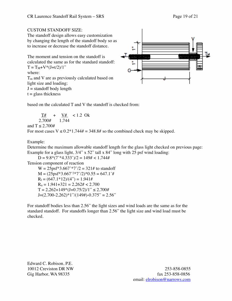
CUSTOM STANDOFF SIZE:The standoff design allows easy customization by changing the length of the standoff body so as to increase or decrease the standoff distance.
The moment and tension on the standoff is calculated the same as for the standard standoff:T = TM+V*(J+t/2)/1”where:Tm and V are as previously calculated based on light size and loading;J = standoff body lengtht = glass thickness
based on the calculated T and V the standoff is checked from:
T# + V# < 1.2 Ok 2,700# 1,744and T ≤ 2,700#For most cases V ≤ 0.2*1,744# = 348.8# so the combined check may be skipped.
Example:Determine the maximum allowable standoff length for the glass light checked on previous page:Example for a glass light, 3/4” x 52” tall x 84” long with 25 psf wind loading: D = 9.8*(7’*4.333’)/2 = 149# < 1,744#Tension component of reaction W = 25psf*3.667’*7’/2 = 321# to standoff M = (25psf*3.667’2*7’/2)*0.55 = 647.1’# Rl = (647.1*12)/(4”) = 1,941# Ru = 1,941+321 = 2,262# < 2,700 T = 2,262+149*(J+0.75/2)/1” ≤ 2,700# J=(2,700-2,262)*1”/(149#)-0.375” = 2.56”
For standoff bodies less than 2.56” the light sizes and wind loads are the same as for the standard standoff. For standoffs longer than 2.56” the light size and wind load must be checked.
CR Laurence Standoff Rail System – SRS Page 19 of 21
Edward C. Robison, P.E.10012 Creviston DR NW 253-858-0855Gig Harbor, WA 98335 fax 253-858-0856 email: [email protected]

RSOB20 STANDOFF FITTINGBracket strengthBending in plate:Bracket bending strength: Z = 4”*(0.375)2/4 = 0.1406 in3
øMn = 0.85*30 ksi* 0.1406 in3 = 3,585”#Ms = øMn/1.6 = 3,585/1.6 = 2,241”#
Allowable moment on glass standoff:M = 2*2,241”# = 4,482”#Or allowable tensionT = 2,241*4.93/3.5” = 3,157#Bracket bending will not limit standoff loads below the values based on the stud strength.
Bracket reactions on anchors:
Anchors form couple to resist moment on the guards.Determine anchor tension from ∑M about the bottom of the bracket:∑Mb = w*B*H2/2 +V*2.25”– n2T(7.5”+42/7.5)solving for T:T = (12”/ft*w*B*H2+2.25V)/(38.5”n)If V is dead load only:V = 9.8psf*B*H/2substitute and simplifyT = [12*w*B*H2+11.025B*H)]/(38.5”n)where n = number of brackets
For typical maximum light size and load:3/4” x 52” tall x 84” long with 25 psf wind loadingT = [12*25*7*4.3332+11.025*7*4.333)]/(38.5”)T = 344#/ fastener
Typical fastener:1/2” x 3” lag screw to wood or3/8” x 3” expansion bolt to concrete or3/8” bolt to steel.
CR Laurence Standoff Rail System – SRS Page 20 of 21
Edward C. Robison, P.E.10012 Creviston DR NW 253-858-0855Gig Harbor, WA 98335 fax 253-858-0856 email: [email protected]

Cap Rail/ Grab RailFor guard installations – Fall protection required, a cap rail or grab rail is required.
Cap rails and grab rails are the same as used in the GRS – Glass Rail System, refer to the GRS engineering report for the cap rails and grab rails.
All cap rails intended for use with the GRS may be used with the SRS for the appropriate glass thickness.
All grab rail brackets used with the GRS may be used with the SRS. The grab rail brackets’ installation and strength is the same as for the GRS.
Other Glass Thicknesses and Laminated Glass
The Standoffs may be used with glass thicknesses other than 1/2” and 3/4”. The standoffs may also be used with laminated glass. When used with other glass thicknesses or laminated glass the glass bending moment shall be evaluated using the amplification factors and procedures in this report.
CR Laurence Standoff Rail System – SRS Page 21 of 21
Edward C. Robison, P.E.10012 Creviston DR NW 253-858-0855Gig Harbor, WA 98335 fax 253-858-0856 email: [email protected]