educational services ltd
TRANSCRIPT

ccredited and registered provider
EDUCATIONAL SERVICES LTD
Student Name _________________________________________ Date __ / __ 2019
Marked By: %
Feedback Excellent work
Good work
Please attempt all questions
Please resubmit
1

This document is the copyright of Fairview Educational Services Limited and may not be reproduced in any form without its express written permission.
2
Page 4 Key words
Page 5 Functions of a cooling system
Page 6 Types of cooling systems
Page 6 Direct cooling system
Page 9 Section Overview
Page 10 Review Questions One
Page 13 Indirect cooling
Page 20 Section Overview
Page 21 Review Questions Two
Page 25 Safety when servicing vehicles
Page 27 Protective clothing
Page 28 Using lifting equipment
Page 29 Why do cooling systems fail?
Page 32 Servicing an indirect cooling system
Page 56 Section Overview
Page 57 Review Questions Three
Page 61 Cooling system word search
Page 62 Elements and Performance Criteria
CONTENTS

This document is the copyright of Fairview Educational Services Limited and may not be reproduced in any form without its express written permission.
3
What is the objective of this unit? To inspect and service cooling systems. What is this unit about? It’s about these elements:
Prepare to inspect and service cooling system Inspect cooling systems Service cooling system Complete work processes How will I be assessed? Assessment will take place when you are confident that you have acquired the skills and the underpinning knowledge necessary to successfully complete the unit. Practical skill assessment will take place only after a period of supervised practiced and repetitive experience. You must be able to meet all the requirements of this unit without direct supervision. Where can I find the Elements and Performance Criteria? At the back of this workbook.
STANDARD AURTTC001

This document is the copyright of Fairview Educational Services Limited and may not be reproduced in any form without its express written permission.
4
It is recommended that students learn the meaning and the correct spelling of the following key words that are particularly relevant to these unit standards. Thermostat: Corrosion: Radiator: Gasket: Manifold: Coolant: Reservoir: Temperature: Specific: Gravity: Inhibitor: Additive: Pressure: Variable: Gauge: It is recommended that you are familiar with the following words and their definitions to help your understanding of the material contained in this workbook. Excessive: Going beyond the proper limit Contamination: Material/s that makes a substance impure/no longer fit for use Optimal: Most desirable Exposed: Open Deterioration: Gradual decline in quality Compatible: Able to exist together Efficient: Best possible result with least amount of time and effort Synthetic: Substances made by chemical process Contract: To become smaller Evaporate: To convert from a liquid or solid into gas Discharge: To release Flammable: Can burn or catch fire Warranty: A written guarantee/promise of a products quality Diagnosis: Determine the cause of a problem Feasibility: Capable of being done
KEY WORDS

This document is the copyright of Fairview Educational Services Limited and may not be reproduced in any form without its express written permission.
5
The function of the engine’s cooling system is to remove excess heat from the engine, to keep the engine operating at its most efficient temperature, and to get the engine up to the correct temperature as soon as possible after starting. Ideally, the cooling system keeps the engine running at its most efficient temperature no matter what the operating conditions may be. THE PRINCIPLES OF COOLING To understand the operation of cooling systems it is important to understand some of the basic laws of physics that apply. Heat is a form of energy and is measured in Kilojoules. When a substance is heated its temperature rises and when it is cooled its
temperature falls. Heat always flows from hot to cold. Cold objects have less heat than hot objects of the same mass. Heat can cause a change of state in a solid, liquid or gas. Heat can change the colour of metals. Heat can cause a substance to expand when applied and contract when removed. As fuel is burned in the engine, about one third of the energy in the fuel is converted into power. Another one third goes out the exhaust pipe unused and the remaining third becomes heat energy. HEAT TRANSFER Heat travels in three ways: conduction, convection, and radiation Conduction- conduction is the transfer of heat by direct contact. In an engine the metal components conduct heat from the combustion chamber to the cooling system. Metal is a good conductor of heat. Convection - convection is the transfer of heat by movement of warmed liquid or gas. Hot molecules are lighter than cold molecules and tend to rise. Convection allows hot coolant to pass through the hose to the radiator. Radiation - radiation is the transfer of heat across in space. When the rays strike a cold object heat is produced, this heat raises the temperature of the receiving body. Dark-coloured materials are better heat radiators than light-coloured materials and tend to be used in automotive radiators. Temperature - Temperature is a measure of heat or coldness of a substance. It is measured in degrees Centigrade or degrees Fahrenheit. Conversion table
Centigrade (C) Fahrenheit(F) 0 32 50 122 100 212
FUNCTIONS OF A COOLING SYSTEM
Start Reading
Laws of Physics
Direct contact
Movement

This document is the copyright of Fairview Educational Services Limited and may not be reproduced in any form without its express written permission.
6
Air Cooled Motorcycle Engine
There are two main cooling systems that are used in automotive vehicles: direct cooling and indirect cooling. Direct cooled engines rely on a moving air stream to cool engine components. Direct Cooling systems are used on: Aircraft Motorcycles Chainsaws Motor mowers Stationary engines Automotive vehicles such as VW and
Porsche Indirect cooled engines rely on a coolant to transfer heat away from the engine into the radiator. Indirect cooling systems are used on: Motorcycles Automotive vehicles such as Ford, Holden and Toyota Stationary engines
Direct cooling systems rely on a moving air stream to cool engine components. There are two types of air stream that can be created: draught air and forced air. Vehicles that have engines open to the atmosphere tend to rely on draught air. The speed generated by the moving vehicle creates an air flow that circulates around the engine components and cools them down. However, difficulties can arise if the engine is running but the vehicle is not moving. In this case the air stream created is not enough to cool the engine components and over-heating may occur. Motorcycles and small engines generally rely on draught air for cooling. Vehicles that have engines enclosed under a bonnet require a fan operated system to force air through and around the engine block. To maximise the effect of the forced air, shrouds are used to direct the air to the hottest engine components. In general, a multi-bladed turbo fan is mounted in sheet steel, semi-circular housing, drawing in air through the fan centre and directing it down to each pair of finned cylinders. The cylinders are shrouded with sheet steel covers and are contoured to direct the air over the full surface area of the cylinder cooling fins. A Bellow’s type thermostat is normally used to control the supply of air to the cylinders.
TYPES OF COOLING SYSTEM
DIRECT COOLING SYSTEM
Moving air stream
Water cooled
Draught air
Multi Bladed Turbo fan

This document is the copyright of Fairview Educational Services Limited and may not be reproduced in any form without its express written permission.
7
Axial Flow Fan
BELLOWS TYPE THERMOSTAT A Bellows type thermostat controls flaps which restrict the air flow during engine warm up. As engine temperature rises to operating level the bellows expand and force the flap to the open position. This allows the heat build up in the ducting to be released and normal operating temperature to be maintained. DIRECT AIR COOLING FANS The two most common types of cooling fans are: Radial Flow Fan- This fan is designed to deflect air flow outwards, forcing the air through the metal ducting and into the shrouds. Radial fans tend to be used on light vehicle engines.
Axial Flow Fan –This fan is designed to accelerate air flow through the fan and into ducting and shrouds. To check the fan/blower unit remove the drive belt and manually spin the fan. Any vibrations may indicate worn bearings. Check the condition of the drive belt to for evidence of fraying and wear. Replace the drive belt as necessary.
Restricts air flow
A Bellows Type Thermostat
A Radial Flow Fan Alternator
Drive Pulley
Radial Fan Deflects air
outwards
Accelerates air flow

This document is the copyright of Fairview Educational Services Limited and may not be reproduced in any form without its express written permission.
8
Ducting Fan Shrouds
COOLING FINS The cylinder head and cylinder barrels on air cooled engines incorporate cooling fins in their construction. The cooling fins are designed to dissipate heat created in the engine during operation, and to be exposed to an air flow from the cooling fan to remove heat. It is necessary to periodically remove dust, dirt and sludge from the finned areas to ensure that the engine is cooled efficiently. This may require the removal of the engine shrouds to gain access to the fins. To clean cooling fins: 1. Use a scraper to remove dirt deposits from the finned
areas. It is advisable to use a plastic or wooden scraper to avoid damaging the fins.
2. Use an engine degreaser and a cleaning brush to thoroughly clean the area.
3. Hose off with cold water.
4. Refit the shrouds ensuring that they are mounted
correctly. Likely causes of direct cooling system failure include: Blocked fins on the cylinder head and barrel. Lack of air circulation. Damaged or blocked air ducting and shrouds. Drive belt failure. Cooling fan failure. Thermostat failure. Advantages of direct cooling systems include: Lightweight construction. Low cost construction. (no coolant, inhibitors,
radiator or hoses required) Operating optimal engine temperature quickly
reached. Low service requirements. The possibility of leaks is eliminated. Disadvantages of direct cooling systems include: Noisy engine operation. Engine will overheat if air stream is not maintained
during vehicle operation. Difficult to tell when the engine is overheating. System requires larger component heat tolerances. Warning signs of direct cooling system failure include: Loss of power and noisy operation. Burning odour.
Dissipate heat
Cylinder Head Fins
A Section View Of A Direct Cooling System Noisy
operation
Air circulation
This document is the copyright of Fairview Educational Services Limited and may not be reproduced in any form without its express written permission.
9
SECTION OVERVIEW The function of the cooling system is to remove excess heat from the engine Heat travels in three ways: Conduction, Convection, and Radiation. Heat always flows from hot to cold Heat will change the colour of metals Heat will cause a change in state of a liquid When heat is removed it can cause a substance to contract. Temperature is measured in degrees Centigrade or degrees Fahrenheit. The two main types of cooling systems are the Direct Cooling System and the Indirect Cooling System. Direct cooling systems rely on a moving air stream to cool engine components. Indirect cooling systems rely on a coolant to transfer heat away the engine into the radiator. Direct air cooled components include: Cooling fins Air fan/blower Shroud Ducting Bellows type thermostat The two most common direct cooling fans are the Radial Flow Fan and the Axial Flow Fan. Cooling fins are designed to dissipate engine heat.
Key Points

This document is the copyright of Fairview Educational Services Limited and may not be reproduced in any form without its express written permission.
10
REVIEW QUESTIONS ONE Q1 Explain the purpose of an engine’s cooling system?
________________________________________________________________ ________________________________________________________________
________________________________________________________________
________________________________________________________________
Q2 What is the main difference between direct and indirect cooling systems?
________________________________________________________________ ________________________________________________________________
________________________________________________________________
________________________________________________________________
Q3 Explain each of the following:
Conduction
________________________________________________________________
________________________________________________________________
Convection
________________________________________________________________
________________________________________________________________ Radiation
________________________________________________________________
________________________________________________________________

This document is the copyright of Fairview Educational Services Limited and may not be reproduced in any form without its express written permission.
11
Q4 List three of the basic laws of physics that apply to heat.
1. _____________________________________________________________
2. _____________________________________________________________
3. _____________________________________________________________ Q5 Describe how air is used to cool a direct air-cooled engine.
________________________________________________________________
________________________________________________________________
________________________________________________________________
________________________________________________________________
________________________________________________________________ Q6 Name the two ways in which temperature can be measured.
________________________________________________________________ ________________________________________________________________
Q7 What is the purpose of using shrouds in an engine cooling system?
________________________________________________________________
________________________________________________________________
________________________________________________________________ Q8 What is the purpose of a Bellows type thermostat?
________________________________________________________________
________________________________________________________________
________________________________________________________________
This document is the copyright of Fairview Educational Services Limited and may not be reproduced in any form without its express written permission.
12
Q9 Name the two most common types of direct air cooling fans.
________________________________________________________________
________________________________________________________________ Q10 Explain why it is necessary to clean cylinder fins?
________________________________________________________________
________________________________________________________________
________________________________________________________________ Q11 What are the disadvantages of the direct air cooling system?
________________________________________________________________ ________________________________________________________________
________________________________________________________________
________________________________________________________________
Q12 Complete the following sentence:
The cylinder _______________ and cylinder _____________ on air cooled engines ________________ cooling fins in their ___________________. The cooling fins are_________________ to __________________ heat _________________ in the engine during _________________, and to be exposed to an ___________________ from the ______________________ to remove heat.
Q13 Explain how the cooling fins of a direct air-cooled engine should be cleaned.
________________________________________________________________
________________________________________________________________

This document is the copyright of Fairview Educational Services Limited and may not be reproduced in any form without its express written permission.
13
Indirect cooling systems rely on coolant to transfer heat away from the engine into the radiator. Principle of operation
When the coolant is cold, the thermostat is in the closed position and the coolant flow is restricted to within the cylinder block, cylinder head, intake manifold and heater. A bypass circuit allows circulation within the cylinder block during this period. As the temperature rises, the thermostat opens and allows the coolant to pass into the radiator. The coolant flows through the radiator tubes and is cooled by the air passing through the cooling fins, assisted by the cooling fan. Coolant is then circulated from the bottom tank of the radiator up through the water pump and into the cylinder block and cylinder head. It then flows into the top tank of the radiator to complete the circuit. Coolant mixture For the engine to operate efficiently the cooling system will need a mixture of water and an ethylene glycol based solution (anti-freeze). This mixture: Prevents a low boiling point of the water. Prevents rust and corrosion of the cooling system components. Prevents the coolant from freezing. Lubricates water pump seal.
INDIRECT COOLING
Start Reading
Directional Coolant flow
By-pass circuit
Anti-freeze
Intake manifold
Heater core
Water valve Radiator upper hose
Thermostat
Engine
Water pump
Radiator lower hose
Water return pipe
Fan
Radiator
Front
This document is the copyright of Fairview Educational Services Limited and may not be reproduced in any form without its express written permission.
14
Radiator Fitted with Top and Bottom Tanks
Radiator Fitted with Side Tanks – Cross-flow
External Oil Cooler
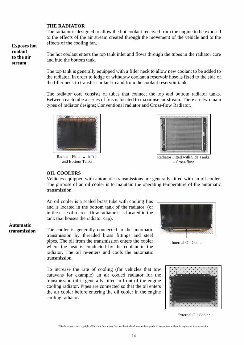
THE RADIATOR The radiator is designed to allow the hot coolant received from the engine to be exposed to the effects of the air stream created through the movement of the vehicle and to the effects of the cooling fan. The hot coolant enters the top tank inlet and flows through the tubes in the radiator core and into the bottom tank. The top tank is generally equipped with a filler neck to allow new coolant to be added to the radiator. In order to lodge or withdraw coolant a reservoir hose is fixed to the side of the filler neck to transfer coolant to and from the coolant reservoir tank. The radiator core consists of tubes that connect the top and bottom radiator tanks. Between each tube a series of fins is located to maximise air stream. There are two main types of radiator designs: Conventional radiator and Cross-flow Radiator.
OIL COOLERS Vehicles equipped with automatic transmissions are generally fitted with an oil cooler. The purpose of an oil cooler is to maintain the operating temperature of the automatic transmission. An oil cooler is a sealed brass tube with cooling fins and is located in the bottom tank of the radiator, (or in the case of a cross flow radiator it is located in the tank that houses the radiator cap). The cooler is generally connected to the automatic transmission by threaded brass fittings and steel pipes. The oil from the transmission enters the cooler where the heat is conducted by the coolant in the radiator. The oil re-enters and cools the automatic transmission. To increase the rate of cooling (for vehicles that tow caravans for example) an air cooled radiator for the transmission oil is generally fitted in front of the engine cooling radiator. Pipes are connected so that the oil enters the air cooler before entering the oil cooler in the engine cooling radiator.
Exposes hot coolant to the air stream
Automatic transmission
Internal Oil Cooler

This document is the copyright of Fairview Educational Services Limited and may not be reproduced in any form without its express written permission.
15
Radiator Cap
THE RADIATOR CAP The radiator cap is designed to hold the coolant in the radiator under a predetermined amount of pressure. The radiator cap ensures that the coolant does not evaporate and cause engine overheating. It is important to understand that a cooling system under pressure takes heat away from the engine faster, which makes the engine more efficient. By increasing the pressure on the coolant, the boiling point of the coolant rises, allowing for the faster movement of heat into the radiator. However, to prevent too much pressure been exerted on the coolant, a radiator cap is fitted. The radiator cap has a pressure relief valve, which has a preset rating, allowing it to take just up to a certain amount of pressure. By turning the radiator cap on the radiator filler neck, the upper and lower sealing surfaces of the filler neck are sealed. The pressure relief valve spring is compressed against the lower seal when the radiator cap is locked. If the pressure in the cooling system exceeds the preset rating, the pressure relief valve allows the excess coolant to flow through the overflow tube and into the coolant reservoir. When the coolant cools down the coolant will contract. The vacuum relief valve opens allowing coolant to flow back into the radiator from the reservoir. RESERVOIR TANK The reservoir tank is connected to the radiator by an overflow hose. When the temperature rises in the cooling system, the coolant volume expands, resulting in excess coolant. This excess coolant is transferred into the reservoir tank. As the temperature falls the coolant is transferred back into the radiator. This prevents wasteful discharge of the coolant and reduces the need for refilling of the cooling system. RADIATOR HOSES Radiator rubber hoses are used to connect the engine and the water pump to the radiator. The three main types of hoses used include: The Straight Radiator Hose This hose is straight and cannot take much bending before collapsing. It is made of rubber with fabric reinforcement to increase its strength when under pressure from the hot coolant within.
Preset rating
Pressure relief valve
Over flow hose
Reservoir Tank Removing a Reservoir Cap
Straight Radiator Hose
Main types of hose
Vacuum relief valve

This document is the copyright of Fairview Educational Services Limited and may not be reproduced in any form without its express written permission.
16
V-Belt
V-Ribbed Belt V-ribbed belts have v-shaped ribs to provide maximumcontact pressure on the pulleys. They tend to have greaterresistance to heat and wear than V-belts.
The Shaped Radiator Hose This hose has a similar construction to the common hose, except that it has bends moulded into the hose during construction.
Accordion Type Radiator Hose This hose can withstand bending and can absorb some of the vibration between the engine and the radiator.
DRIVE BELTS A drive belt is used to connect the cooling fan to the crankshaft pulley. The rotational action of the crankshaft pulley drives the cooling fan. There are three main types of drive belts:
Tooth Drive Belt Tooth drive belts have teeth moulded across the belt to provide maximum grip. COOLING FAN A cooling fan is designed to cool the coolant in a radiator. It is generally located behind the radiator and is driven by a drive belt or an electric motor. Cooling fans can have from two to ten angled blades, which can be constructed of either steel or plastic. Often the radiator has a shroud for the fan to keep it from re-circulating the same hot air that has been collected behind the radiator.
Solid state fan A solid state fan is driven constantly by the action of the crankshaft via a drive belt. The speed of the fan is directly related to the speed of the engine.
Shaped Radiator Hose
Accordion Type Radiator Hose
Angled blades
Moulded hose
Crankshaft driven
Maximum grip
V-Belt V-belts have a v-shaped cross section and are generallyconstructed of synthetic and canvass cladding. The designof the V-belt increases contact pressure between thefriction surfaces allowing the belt to be pulled deep intothe grooves of the pulley.
V-Ribbed Belt
Tooth Drive Belt

This document is the copyright of Fairview Educational Services Limited and may not be reproduced in any form without its express written permission.
17
Water Pump, Gasket and Seal
Thermostatic Fan Clutch
Flex Fan A flex fan is also driven by the action of the crankshaft via a drive belt. However, it has flexible blades that straighten as the engine speed increases. This action reduces fan resistance and aids in fuel economy. Thermostatic Fan Clutch (variable speed fan) A thermostatic fan clutch has a temperature-controlled spring that opens and closes a clutch plate, to reduce drive torque when it isn’t needed. This allows the fan to operate only when the engine is hot. It has a fluid coupling partly filled with Silicone oil, that when combined rotates the fan. If the temperature of the air passing through the radiator rises, the heat allows a bi-metal coil spring to contract or expand. When it expands it allows more oil to enter the fluid coupling, so that the fluid coupling rotates the fan. As the temperature drops the coil spring contracts and the oil leaves the fluid coupling. Slowing the fan in this way when it is not needed reduces fuel consumption, saves engine power and makes less noise. Electric Fan An electric fan is driven by an electric motor (either permanent magnet or wire wound type), which operates when it receives a signal from a coolant temperature sensor. The coolant temperature sensor is generally attached to the cylinder head, and as the temperature reaches a predetermined setting it starts the electric motor. An electric fan operates only when it is needed allowing the engine to reach its ideal temperature more quickly. WATER PUMP The water pump is generally located at the front of an engine block and is designed to circulate the coolant in the cooling system. It is constructed of a cast alloy housing, with a bearing mounted main shaft and impeller. To prevent the coolant from leaking, the water pump is fitted with a seal that fits between the housing and the impeller shaft and with a gasket that is placed between the water pump housing and the engine block. The water pump is fitted with a pulley that is driven by a drive belt that connects to the crankshaft.
Flexible blades
Flex Fan
Bi-metal spring
Fluid coupling
Temperature Sensor
Electric Fan fitted to a Radiator
Circulates coolant

This document is the copyright of Fairview Educational Services Limited and may not be reproduced in any form without its express written permission.
18
THERMOSTAT A thermostat is a temperature sensitive spring valve that automatically opens and closes according to the coolant temperature. During engine warm up the thermostat remains closed and blocks the flow of coolant to the radiator. However, a coolant by-pass allows the water pump to circulate coolant throughout the cylinder block and heads. This internal re-circulation promotes fast, uniform start up. By bringing all parts of the engine up to the operating temperature as fast and as evenly as possible, it reduces combustion blow-by, improves cold engine lubrication, minimises wear of cylinder walls, pistons, bearings, etc, as well as aiding better combustion during the engine warm up period. As soon as the thermostat begins to open, the hot coolant is pumped out of the engine and into the upper radiator tank. The most common thermostat used on modern motor vehicles is the Wax Element Type Thermostat. A wax pellet in the thermostat expands when heated and contracts when cooled. This pellet is connected through a piston to a valve plate. When the pellet is heated, pressure is exerted against the rubber diaphragm, which then forces the valve plate to open. As the pellet cools below the optimal temperature level (usually optimal engine operating temperature is between 180° F and 200°F) the contraction allows a spring to close the valve. When the engine becomes cold (engine off for several hours) the valve plate closes completely. The opening and closing of the valve in the thermostat maintains the correct engine operating temperature in a properly operating cooling system. WELSH PLUGS Welsh plugs are small plugs used to seal the casting holes in the engine block and cylinder. They expand and flatten as they are driven into place, and make a tight seal. They are designed to hold the pressure of the cooling system, but to pop out if the coolant in the cylinder block ever freezes.
Coolant by-pass
Wax Element Type Thermostat Wax pellet
Tight seal
Cup Type Welsh Plug Cup Type Welsh Plug fitted to a Cylinder block
Dish Type Welsh Plug

This document is the copyright of Fairview Educational Services Limited and may not be reproduced in any form without its express written permission.
19
Senses coolant temperature
Cylinder Head Water Jackets
Cylinder Block Water Jackets
COOLING SYSTEM ELECTRICAL SENSORS The cooling system is fitted with electrical sensors to operate gauges, switches and the electric fan. The types of electrical sensors used include: A Temperature Sender Unit - that is designed to sense the coolant temperature and send the information electronically to the temperature gauge. This sender unit is generally located on the cylinder head of the engine, close to the thermostat housing. An Electric Fan Sender Unit - that is designed to send an electrical current to start the electric fan through a heat sensitive magnetic switch. It is generally located in either the top or bottom tanks of a radiator. WATER JACKETS The water jacket is a collection of passages within the engine block and cylinder head that allow the coolant to circulate around the engine hot spots in order to cool them down. When the optimal engine operating temperature is reached, the water pump forces the coolant through the head gasket openings and on into the water jackets in the cylinder head. Once in the water jacket, the coolant absorbs the heat given off by the components before flowing back into the radiator via the top hose.
Likely causes of indirect cooling system failure include: Thermostat failure Coolant leak Lack of coolant Water pump failure Gasket failure Corrosion of cylinder heads, cylinder block and radiator Cooling fan failure Drive belt failure Hose failure
Temperature Sender Unit
Electric Fan Sender Unit
Engine hot spots
Areas of failure

This document is the copyright of Fairview Educational Services Limited and may not be reproduced in any form without its express written permission.
20
Warning signs of indirect cooling system failure include: Hot reading from the temperature gauge. Illuminated control lights such as: charging system warning light, engine oil
light, and coolant warning light. Steam rising from under the vehicle bonnet. Coolant leaks visibly from under the vehicle. Advantages and disadvantages of Indirect cooling systems Advantages include: Operating temperature of the engine can be monitored and controlled. Low engine operating noise. Even distribution of engine heat. Disadvantage includes: High maintenance costs. Heavy engine construction. Regular servicing required. Marine Cooling Systems Just like regular car engines marine engines need to be cooled to avoid overheating. Most marine engines use the surrounding water (salt or fresh) to help with the cooling process. Keel Cooling This is a closed cooling system similar to indirect vehicle system with the exception that there is no radiator (heat exchanger). Instead this system transfers the hot coolant through pipes that are connected to the outside of the hull which are exposed to the cooling effects of the surrounding water. Heat Exchanger This system uses a combination of an indirect cooling system and surrounding water (raw water) to cool the coolant. A raw water pump draws water up into the heat exchanger jacket where it absorbs the heat from the coolant that is flowing through the heat exchanger. The raw water is then pumped back into the surrounding water by the pump. Raw water This system uses a belt driven raw water pump to draw up surrounding water to directly cool the engine. The raw water flows through the engine water jacket and ports before existing through the exhaust back into the surrounding water. Clearly the potential for corrosion is significant when using raw water particularly if salt water is used.
Take Note *
Keel cooling pipes

This document is the copyright of Fairview Educational Services Limited and may not be reproduced in any form without its express written permission.
21
Sacrificial anode
Sacrificial Anodes To try to slow the corrosion process down sacrificial anodes are commonly used. These blocks are usually made from zinc, magnesium or aluminium alloy. The intention when using sacrificial anode is for the block to corrode before the metal that is used in the boat construction (parent metal). To achieve this the block must have a connection to the parent metal. The blocks are usually placed close to the engine and cooling system to ensure that a small electrical connection is maintained. By regularly replacing the blocks the boat owner can limit cooling system corrosion.
SECTION OVERVIEW Indirect Cooling Systems rely a coolant to dissipate engine heat. To operate efficiently cooling systems need a mixture of water and ethylene glycol based solution (antifreeze). Indirect cooling system components include: Radiator Cooling Fans Oil Coolers Water Pump Radiator Cap Thermostat Reservoir Tank Welsh Plugs Radiator Hoses Electrical Sensors Drive Belts Water Jackets There are several methods used to cool marine engines. These include: Raw water cooling Keel cooling Heat exchanger
Key Points

This document is the copyright of Fairview Educational Services Limited and may not be reproduced in any form without its express written permission.
22
REVIEW QUESTIONS TWO Q14 What is the purpose of the radiator in the cooling system?
________________________________________________________________
________________________________________________________________
________________________________________________________________ Q15 What is the purpose of a pressure relief valve on a radiator cap?
________________________________________________________________
________________________________________________________________
________________________________________________________________ Q16 Explain how the coolant is transferred to and from the reservoir tank.
________________________________________________________________
________________________________________________________________
________________________________________________________________ Q17 Explain how a water pump is driven.
________________________________________________________________ Q18 Where is the water pump generally located?
________________________________________________________________ Q19 Name the two main parts that enable a thermostatic fan clutch to operate?
________________________________________________________________
________________________________________________________________ Q20 Name four types of fans that may be fitted to an indirect cooled vehicle.
________________________________________________________________
________________________________________________________________
This document is the copyright of Fairview Educational Services Limited and may not be reproduced in any form without its express written permission.
23
Q21 Explain why the thermostat remains closed during engine warm up.
________________________________________________________________
________________________________________________________________
________________________________________________________________ Q22 Complete the following sentence:
A thermostat is a _________________ sensitive ________________ _____________that ________________ opens and ________________ according to the ___________temperature.
Q23 Describe how a wax element type thermostat operates.
________________________________________________________________
________________________________________________________________
________________________________________________________________
________________________________________________________________ Q24 Name the three main types of radiator hoses used in the cooling system.
________________________________________________________________
________________________________________________________________
________________________________________________________________ Q25 Explain the purpose of the v-shaped construction of drive belts.
________________________________________________________________
________________________________________________________________
________________________________________________________________ Q26 Where are water jackets normally located in an engine?
________________________________________________________________

This document is the copyright of Fairview Educational Services Limited and may not be reproduced in any form without its express written permission.
24
Q27 Complete the following sentence.
Vehicles ______________ with automatic transmissions are generally fitted with an _____________________. The ______________ of an oil cooler is to ______________the _______________ ___________________ of the automatic transmission.
Q28 List four warning signs of indirect cooling system failure.
_________________________________________________________________
_________________________________________________________________
_________________________________________________________________ Q29 Explain the purpose of a temperature sender unit.
_________________________________________________________________
_________________________________________________________________
_________________________________________________________________
Q30 Explain the functions of the following cooling system components
Welsh plugs
________________________________________________________________
________________________________________________________________
________________________________________________________________
Reservoir tank ________________________________________________________________ ________________________________________________________________ ________________________________________________________________

This document is the copyright of Fairview Educational Services Limited and may not be reproduced in any form without its express written permission.
25
Water jackets
________________________________________________________________
________________________________________________________________
________________________________________________________________
Water pump
________________________________________________________________
________________________________________________________________
________________________________________________________________
Drive belt
________________________________________________________________
________________________________________________________________
________________________________________________________________
Radiator cap
________________________________________________________________
________________________________________________________________
________________________________________________________________

This document is the copyright of Fairview Educational Services Limited and may not be reproduced in any form without its express written permission.
26
Appropriate service methods and correct repair procedures are essential for safe, reliable operation of all motor vehicles as well as the personal safety of the individual doing the work. The following list contains some general warnings that you should follow when working on a vehicle.
WARRANTY It is important that before any work or diagnosis is carried out on a vehicle that the technician is aware of the vehicle warranty status. The technician needs to consider each of the following: Is the vehicle covered by a manufacturer’s warranty? Is the vehicle covered by a parts and service warranty? Has the owner taken out mechanical insurance?
Start Reading
SAFETY WHEN SERVICING VEHICLES
WARNING Wear safety glasses for eye protection, where appropriate. Use safety stands whenever a procedure requires you to be under the vehicle. Ensure that the ignition switch is always in the off position, unless otherwise
required by the procedure. Set the hand brake when working on the vehicle. If you are working on an
automatic transmission, set it in park unless otherwise required by the procedure.
Operate the engine only in a well-ventilated area to avoid the danger of carbon monoxide.
To prevent serious burns, avoid contact with hot metal parts such as the radiator, exhaust manifold, tail pipe, catalytic converter and muffler.
To avoid injury, always remove rings, watches, loose hanging jewellery, and loose clothing before beginning to work on a vehicle. Tie long hair behind the head.
Keep hands and other objects clear of the radiator fan blades. Electric cooling fans can start to operate at any time by an increase in temperature.
Avoid contacting the eyes or skin with acid, cooling system additives or brake fluid. Immediately seek medical advice if these fluids are swallowed.
Do not use petrol or highly flammable spirits when cleaning parts. All general health and safety practices should be observed. Seek additional
advice if necessary. WHS requirements, including individual State/Territory regulatory
requirements and personal protection needs are observed throughout the work. Procedures and information such as workshop manuals and specifications, and
tooling required, are sourced. Methods appropriate to the circumstances are selected and prepared in
accordance with standard operating procedures. Resources required for cooling system inspection are sourced and support
equipment is identified and prepared.
Very Important Safety Point
Insurance
This document is the copyright of Fairview Educational Services Limited and may not be reproduced in any form without its express written permission.
27
In general your supervisor will inform you of the warranty status of a vehicle. From the information provided the technician should be aware of the following: The allocated labour time to complete the repair. The procedure for handling parts covered by the warranty. The procedures for recording the repair process, which will typically include
fault (the component that fails to operate), cause (why the component failed to operate) and remedy (process to repair/replace the faulty component).
Cost of repair Once the fault has been diagnosed within the system the customer should be advised on two key points. 1. The feasibility of repairing the defective component. 2. The cost of a replacement component. The technician is responsible for determining whether a component can be economically repaired or whether it will need to be replaced. The technician’s diagnosis should be passed on to the workshop supervisor for consideration. LIFTING HEAVY OBJECTS It is important to adopt the correct lifting techniques when lifting cooling system components to avoid serious physical injuries. Remember to: Bend at the knees and crouch as close as possible to the component being lifted. Ensure that your back is kept straight while crouching. Grip the component firmly with both hands. During the lift maximise the use of your leg muscles. Avoid twisting the body or jerking the wheel from the vehicle. Place the component on the ground or on the workbench using the same
technique with your legs. If you are unable to lift the battery, STOP! Seek assistance.
ASPHYXIATION
Asphyxiation is a state of suffocation brought on by a lack of oxygen. It is generally caused by a combination of toxic fumes and poor ventilation. The symptoms include: Dizziness Headaches Feeling sick Loss of consciousness. In a workshop it is important to understand the dangers of asphyxiation. Work should always be carried out in well-ventilated areas, and where this is not possible breathing equipment should be worn. To ensure good ventilation keep workshop doors and windows open, use extractor fans, minimise the running of engines and use respiratory as required. Particular care should be taken when exposed to coolant inhibitors. In the event that a poison has been swallowed contact the Poisons Information Centre on 13 11 26 for advice.
Take Note *
Economic repairs
“Don’t Use Your Back as a Crane”
Lack of Oxygen
Ventilation
Respiratory protection
must be worn
This document is the copyright of Fairview Educational Services Limited and may not be reproduced in any form without its express written permission.
28
Overalls
Safety Gloves
Protective clothing is designed to protect workers from injury. Areas of the body that need protection include eyes, ears, feet, body, head, lungs and hands. When using tools and machinery to inspect, service and repair cooling systems it is the employee’s responsibility to wear the appropriate protective clothing and to follow the recommended safety procedures.
PROTECTIVE FOOTWEAR
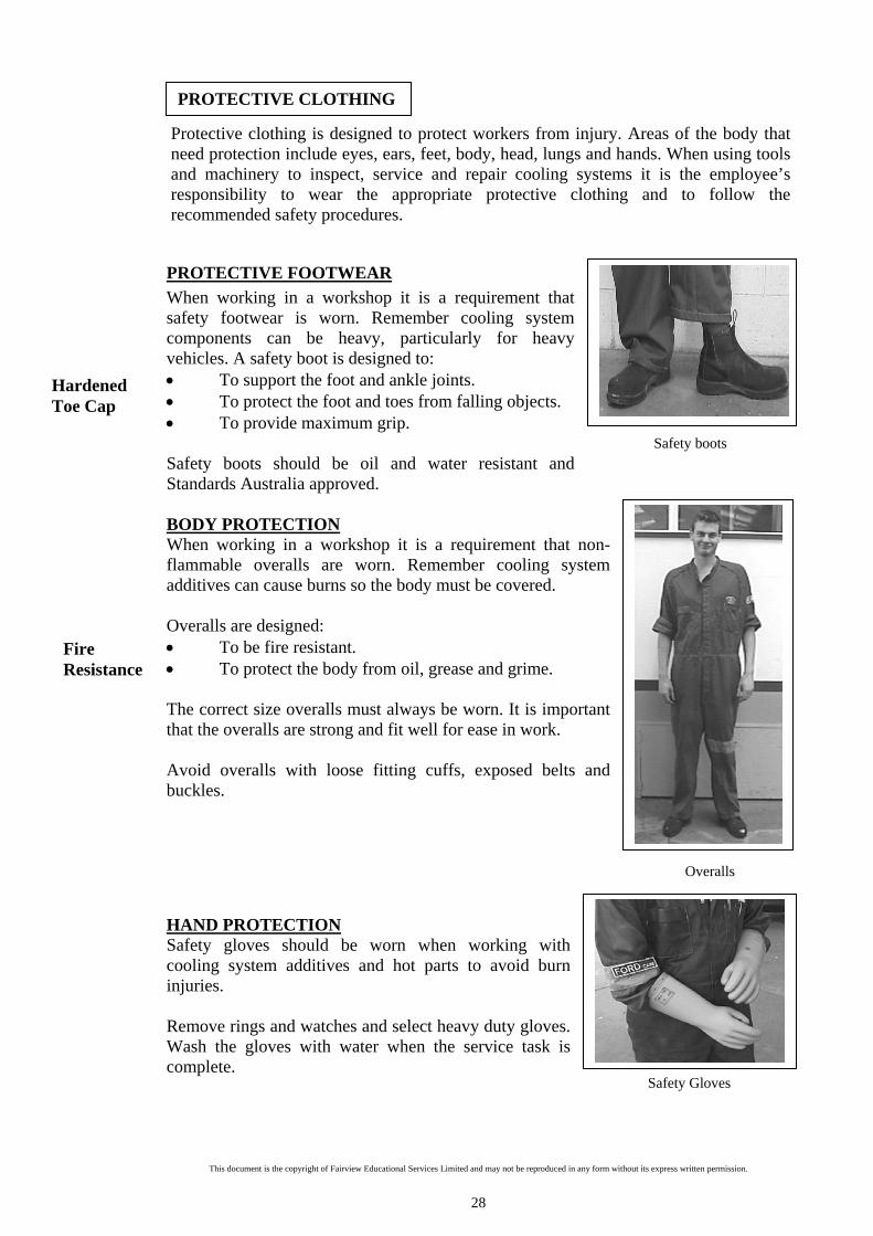
When working in a workshop it is a requirement that safety footwear is worn. Remember cooling system components can be heavy, particularly for heavy vehicles. A safety boot is designed to: To support the foot and ankle joints. To protect the foot and toes from falling objects. To provide maximum grip. Safety boots should be oil and water resistant and Standards Australia approved. BODY PROTECTION When working in a workshop it is a requirement that non-flammable overalls are worn. Remember cooling system additives can cause burns so the body must be covered. Overalls are designed: To be fire resistant. To protect the body from oil, grease and grime. The correct size overalls must always be worn. It is important that the overalls are strong and fit well for ease in work. Avoid overalls with loose fitting cuffs, exposed belts and buckles.
HAND PROTECTION Safety gloves should be worn when working with cooling system additives and hot parts to avoid burn injuries. Remove rings and watches and select heavy duty gloves. Wash the gloves with water when the service task is complete.
Hardened Toe Cap
Fire Resistance
PROTECTIVE CLOTHING
Safety boots

This document is the copyright of Fairview Educational Services Limited and may not be reproduced in any form without its express written permission.
29
Working With a Two Post Hoist
Using Jacking Equipment
EYE PROTECTION Safety goggles should always be worn when there is a risk of eye damage. The main risk when working with cooling systems is additive splashes and steam burns. HOISTS Before using the hoist check that it has a valid and current service certificate. Do not exceed the maximum lifting capacity as displayed on the hoist. When using vehicle hoists remember to: Align the vehicle with the centre of the hoist
and drive slowly into position.
Ensure that all locking devices are operational and in place.
Ensure that the lifting arms are located to the
vehicle jacking points. Wear eye protection, boots, overalls and
gloves as appropriate. Check that there is sufficient ceiling
clearance. Remove all tools and equipment from the
area below the vehicle before lowering the vehicle.
Stand well clear when raising or lowering a vehicle.
JACKING EQUIPMENT
When using jacking equipment remember to: Wear overalls and boots.
Check that the equipment is safe to
operate. Locate the vehicle jacking points. Never work under a vehicle without axle
stands in place.
Ensure that the vehicle is on hardened level ground.
Watch out for the protruding jacking handle.
Clear Safety Goggles
Ceiling Clearance
USING LIFTING EQUIPMENT

This document is the copyright of Fairview Educational Services Limited and may not be reproduced in any form without its express written permission.
30
Flakes off
RECYCLING To minimise cardboard and paper waste automotive workshops should strive to reuse boxes and packing when storing and issuing parts. All waste should be stored for collection by the waste management disposal company. All waste products such as oils, chemicals, sludge and glass should be sorted and stored in their appropriate bins for recycling and disposal. Liquid waste must be drained into recycling containers. Dirty hands should be cleaned over drains that are connected to an oil-water separator or into drums for collecting liquid waste.
A poorly maintained cooling system may cause an engine to operate above or below its ideal operating temperature. When an engine is operating above its ideal temperature, engine components may overheat and expand. This is known as over-heating and may result in engine seizure/failure. When an engine is operating below its ideal temperature, engine components over-cool and will not expand enough to meet the engine working tolerances. This is known as over-cooling and may result in excessive wear, loss of horsepower, low fuel economy and possibly engine failure. Likely causes of cooling system failure include: Thermostat failure Coolant leak Lack of coolant Water pump failure Gasket failure Corrosion of cylinder heads, cylinder block and radiator Cooling fan failure Drive belt failure Hose failure Blockage in radiator, cylinder head and/or cylinder block CORROSION Corrosion can be explained as the eating away or deterioration of a solid, especially metal, by a chemical or electrochemical reaction. The main types of corrosion include: 1. Rust Rust and scale forms on the inside of the engine, mainly in the cylinder block water jackets (cast iron). This becomes a problem when the scale flakes off the side wall of the water jackets and travels into the radiator causing the tubes of the radiator to become blocked. 2. Pitting Corrosion Pitting corrosion occurs commonly to metals such as aluminium and stainless steel. It usually develops on the metal underneath a covering of sludge or scale deposits.
WHY DO COOLING SYSTEMS FAIL?
Over-heating
Over-cooling
Electro chemical action

This document is the copyright of Fairview Educational Services Limited and may not be reproduced in any form without its express written permission.
31
3. Electrolysis Corrosion This type of corrosion occurs when two different metals come into contact and set up an electrochemical cell. For example if corrosion has eaten away parts of a copper radiator outlet, the particles may find their way to the aluminium water pump where they will bond with the water pump. Eventually the copper particles will corrode the aluminium housing of the pump. 4. Crevice Corrosion Crevice corrosion takes place in the small confined areas where moisture is present but coolant flow is weak or non-existent, for example, the area where the radiator and radiator hose are clamped together. An easy way to detect this type of corrosion is to note the sweating of the radiator hose around the clamping area. The metal will corrode and expand from the outside inwards. Gasket surfaces and head gaskets surfaces are particularly open to this form of corrosion. Over time corrosion will cause the cylinder head to be corroded to the point where combustion gases enter the cooling system. 5. Cavitation Corrosion The water pump is generally the first component to show signs of this type of corrosion. Air bubbles that rapidly form and collapse hammer away at the pumps housing, until the thin layer of protection built up by the coolant is eroded away to allow the unprotected housing to be exposed to corrosive action. Regular servicing of the cooling system can prevent this type of corrosion as the inhibitor not only builds up a protective film, but aids in removing foaming and the build up of air bubbles. 6. Chemical Corrosion This type of corrosion is caused by a number of factors, such as mixing different types of coolant, using incorrect glycol content within the coolant, or by allowing the coolant quality to be reduced by leaving the coolant in the system for too long. Coolant can last approximately 20-40,000 kms depending on the brand of coolant used. Combustion gases leaking into the cooling system can also reduce the protective qualities of the coolant. 7. Stray Current Corrosion. Stray current is a chemical/electrical process, which causes an electrical current to pass through engine coolant, causing damage to radiators, water pumps, and thermostat housings. This corrosion is caused when one or more electrical items such as headlights or cooling fan have a fault with its wiring circuit. This causes the electrical current to seek out the easier route to earth via the radiator core through the engine coolant. Typical causes of stray current corrosion include: Damaged wire insulation Faulty electric fans Missing earth straps Paint overspray not removed from an earth connection Damaged or faulty relays Build up of conductive dust Incorrect installation of accessories such as driving lights, radio/cd player, trailer
lights.
Bond
Sweating
Air bubbles
Combustion gases
Electrical current
Dirty connections

This document is the copyright of Fairview Educational Services Limited and may not be reproduced in any form without its express written permission.
32
Testing for stray current
Testing for stray current 1. Remove the radiator cap, and run the engine to operating temperature. Note: Removing the radiator cap will reduce the boiling of the coolant; this may cause the cooling fan not to operate on some vehicles. 2. Switch on all electrical items, for example, phone, rear demister, driving lights,
cooling fan (disconnect sender unit)
3. Switch on analogue multimeter to a scale of 5 volts DC or less.
4. Connect the negative lead of the multimeter into
the negative battery post. 5. Place the positive lead of the multimeter into
the coolant. Ensure that the lead does not touch the filler neck or the core of the radiator.
6. A reading of more than 0.05Volts indicates the presence of a potentially
damaging strong current passing through the coolant. Ideally the voltage reading should be zero, but it is common for some low voltage to be present.
7. If no voltage is detected or very low voltage is present, carry out the same test as
in step 4, but the ignition switched off. 8. If voltage is present, isolate the circuit by turning off the electrical components
and then proceed to switch the components back on one by one while checking the voltage reading.
CONTAMINATION Contamination occurs when a foreign substance is mixed with engine coolant due to component failure or leakage. Common areas for coolant contamination include: Engine oil cooler Transmission oil cooler Corroded/leaking head gasket Engine oil cooler Engine oil cooler failure will lead to coolant contamination. This contamination is the result of engine oil seeping into the cooling system. A split cooler line or failed rubber seal are the most likely causes. Transmission oil cooler These coolers are generally situated within the bottom tank of the radiator and are used to cool transmission fluid. If the transmission cooler is damaged, it is possible transmission fluid (red colour) may contaminate the cooling system. Corroded or leaking head gasket A corroded or leaking head gasket will allow combustion gases and possibly engine oil to enter the cooling system. Evidence of oil, discolouration or air bubbles in the coolant when the radiator cap is removed are typical symptoms of a corroded or leaking head gasket.
Zero
Oil seepage
Tar like film
Take Note *

This document is the copyright of Fairview Educational Services Limited and may not be reproduced in any form without its express written permission.
33
Inhibitor and Antifreeze
Prevents rust build up
Oil leakage into the cooling system will cause damage to the engine. As the engine temperature rises, the oil forms a tar like film on the cylinder walls. This leads to scoring on the piston and cylinder walls.
Service Check Tools Required
Specific Gravity Hydrometer for Coolant Coolant Top Up Watering Can Inspecting a Radiator Screwdrivers, Container to collect Coolant, Watering CanPressure Testing Pressure Tester, Screwdrivers, Socket Set, Spanners Radiator Cap Testing Pressure Tester Flushing Cooling System Water Hose, screwdrivers, Container to collect Coolant,
Water Hose Adapter Radiator Hose Inspection Screwdrivers, Container to collect Coolant, Watering CanCooling Fan Checks Socket Set, Spanners, Vehicle Manual Water Pump Inspection Spanners, Socket Set, Stethoscope, Screwdrivers,
Container for collecting Coolant, Watering Can, Gasket Scraper, Gasket Sealant.
Thermostat Testing Socket Set, Spanners, Gasket Scraper, File, Screwdrivers, Thermometer, Container for collecting Coolant, Water Heater, Piece of String, Gasket Sealant
Welsh Plug Checks Inspection Lamp, Mirror Temperature Gauge Checks Multimeter, Jump Wire Water Jackets Inspection Pressure Tester, Compression Tester, Lead Light Mirror COOLANT MIXTURE It is necessary to consult the manufacturer’s specifications when replacing the coolant mixture. The reason for this is that vehicles operate in varying climate conditions and the amount of anti-freeze that is used is reliant on the temperature at which the vehicle operates. Coolant Mixture Chart Cooling System Capacity (ltrs)
-5 C
Anti Freeze
-10 C
Anti Freeze
-15 C
Anti Freeze
-20 C
Anti Freeze 6 1 1.75 2.5 3 9 1.5 2.75 3.75 4.5 12 2 3.5 5 6 15 2.5 4.5 6.25 7.25 18 3 5.25 7.5 9
COOLANT INHIBITORS A coolant inhibitor is used with the anti-freeze solution to prevent the build up of rust, sludge and other foreign material in the cooling system. It is equally important to consult the manufacturer’s specifications to add the correct type coolant inhibitor to ensure it is compatible with the anti freeze being used.
SERVICING AN INDIRECT COOLING SYSTEM
Anti-freeze

This document is the copyright of Fairview Educational Services Limited and may not be reproduced in any form without its express written permission.
34
Taking a Coolant Sample using a Hydrometer
Reading a Hydrometer at Eye Level
Relationship between Anti-freeze and water
SPECIFIC GRAVITY OF COOLANT Specific gravity of coolant measures the relationship between the amount of anti- freeze and water contained in the coolant. A high reading indicates that there is more anti-freeze than water in the coolant. A low reading indicates that there is more water than anti freeze in the coolant. Testing the Specific Gravity of Coolant The specific gravity of the coolant should be checked at the recommended service intervals and the concentration adjusted by adding anti-freeze or water as appropriate. The specific gravity is checked using an anti-freeze test hydrometer when the coolant is cold. Using the hydrometer 1. Using a hydrometer, take a sample of coolant from the radiator when the engine is
cold. 2. Hold the hydrometer at eye level and read the specific gravity reading from the
scale. 3. Compare this reading with the manufacturer’s specifications and adjust as
necessary.
SAFETY WHEN USING COOLING SYSTEM ADDITIVES Always follow manufacturer’s instruction when using a cooling system
cleaning agent. The chemical may cause eye and skin burns. Corrosion Inhibitors Maintain adequate ventilation and do not inhale vapours. Seek medical advice if swallowed. Avoid skin contact. Avoid spills on vehicle paintwork. Do not allow corrosion inhibitor/antifreeze to be poured down the drain.
Very Important Safety Points
Anti-freeze test Hydrometer
Read at eye level

This document is the copyright of Fairview Educational Services Limited and may not be reproduced in any form without its express written permission.
35
Topping Up Engine Coolant
Reservoir Tank
Coolant Additive
Corrosion Inhibitor
Type
Quantity (litre) Minimum
Concentration All Vehicles Motorcraft R1-3B 0.5 5%
Anti-Freeze Concentration
Specific Gravity Approximate % of Anti-Freeze (By volume)
Remains Fluid to ( C)
Solidifies at ( C)
1.080 50 -37 -58 1.065 40 -25 -45 1.050 30 -16 -39 1.042 25 -13 -29 1.034 20 -9 -19 1.026 15 -7 -14 1.016 10 -4 -8
COOLING SYSTEM TOP UP Observe safety when checking a cooling system as serious injury can occur. Sight the fluid level in the coolant reservoir - the level should be between the full
and low marks. If the fluid level is satisfactory no further action is required.
Coolant between Full and Low marks
Reference chart

This document is the copyright of Fairview Educational Services Limited and may not be reproduced in any form without its express written permission.
36
Industry codes of practice
Temperature Control Lever to Hot Position
When the cooling system requires top up: Ensure that the engine is switched off. Allow the cooling system to cool down – 5 to 10 minutes. Do not remove the radiator cap when the engine is hot. Do not lean over the radiator when removing the radiator cap - stand to the
side. Use a thick cloth around the radiator cap and turn slowly to the first stop.
(You will hear a hissing sound. This is the pressure being released.) When the pressure is released (no hissing noise), turn and remove the
radiator cap. Use clean water or anti freeze to top up and fill to the base of the radiator
neck. Top up the overflow bottle (between full and low marks). Securely fasten the radiator and overflow bottle caps before restarting the
engine. CHANGING COOLANT Used coolant must be stored in a specified container ready for collection in accordance with industry codes of practice. Coolant should never be poured into sewerage or storm water drains. Offenders face prosecution for non-compliance. Procedure to follow when changing coolant: 1. Ensure that the engine is cold. 2. Remove the radiator and reservoir caps. 3. Loosen the lower radiator hose (or open the radiator
drain plug if fitted) and let the coolant drain out into a container.
4. Move the heater temperature control lever to the hot
position. (The heater temperature control lever is located on the dash panel).
5. With the hose left loose, flush out the system with
water. 6. Let the system drain completely and refit radiator
hose. 7. Add the recommended amount of corrosion inhibitor
and anti-freeze to provide the required corrosion protection.
8. Fill the reservoir to the Max mark and refit the reservoir cap to just past the first
stop position.
Secure Bottom Hose
Be aware of hot coolant
Inhibitor
Drain Coolant

This document is the copyright of Fairview Educational Services Limited and may not be reproduced in any form without its express written permission.
37
9. Run the engine for ten minutes during which time
slowly add extra coolant 10. Refit the radiator cap by depressing and turning
clockwise to the fully locked position. 11. Top up the reservoir to the Max mark with coolant and
refit the reservoir cap 12. Visually inspect all connections for leaks
Why do radiators fail? It is important to recognise and repair radiator faults early to prevent further damage to the engine. Radiator faults include:
Fault Likely Cause Remedy Fan damage to radiator core
Water Pump Failure Replace Water Pump
Minor Collision Repair Engine Mount Failure Replace Engine Mounts Fin Deterioration Aged Radiator Salt/Sea Water Exposure Replace Radiator Fin Bonding To Core Chemical Deterioration Check Inhibitor Level Loose Radiator Mounting Brackets
Excessive Vibration Check Radiator And Engine Mounts
Poor Soldering Re-solder Over Pressurised Cooling
System Check Radiator Cap Pressure
Electrolysis Poorly Earthed Electrical System
Trace Earth Fault and Repair/Replace Radiator If Necessary
Coolant Leaks Solder Joint Failure Re-solder Pressurised Cooling System Check Radiator Cap Chip Damage To Core Remove / Repair Loose Hose Fittings Secure Hoses Oil In Radiator Head Gasket Failure Repair Head gasket
Flush Radiator Oil Cooler Failure Repair Or Replace Oil
Cooler Internal Deposits Rust Build Up Inside The
Radiator Remove And Flush Radiator Add Inhibitor And Antifreeze
SAFETY WHEN CHANGING COOLANT Do not remove the radiator cap when the engine is hot. Beware of rotating engine parts when topping up coolant.
Very Important Safety Points
Trouble -shooting chart
Maximum mark
Top Up with New Coolant

This document is the copyright of Fairview Educational Services Limited and may not be reproduced in any form without its express written permission.
38
Radiator with Split Frame
Flushing a Radiator Core
SAFETY WHEN INSPECTING AND CLEANING A RADIATOR Wear protective clothing and eyewear. Be aware of hot engine coolant. Adopt safe lifting techniques when removing a radiator from a vehicle.
INSPECTING AND CLEANING A RADIATOR It is important to carry out each of the following checks when servicing a radiator: 1. Ensure that the radiator is securely mounted. 2. Remove the radiator cap and check the condition
of the coolant. 3. Inspect the soldering joints around the filler
neck, top tank, radiator core and bottom tank. 4. Check for a build up of dirt clogging the radiator
fins. It may be possible to remove dirt from the radiator fins by using a low pressure water or air hose to force the dirt build up back through the radiator fins. Never force the dirt build up inwards.
5. It may be necessary to remove the radiator top
and bottom tanks in order to carry out a radiator core flush.
Cleaning Radiator Core with a Low Pressure Water Hose
Low pressure water or air hose
Very Important Safety Points

This document is the copyright of Fairview Educational Services Limited and may not be reproduced in any form without its express written permission.
39
Removing a Radiator Cap
Attaching a Pressure Tester
A Pressure Gauge
PRESSURE TESTING Pressure testing is carried out to identify leaks from the cooling system. To Test 1. Remove the radiator cap 2. Top up with coolant to the rim of the filler neck.
3. Attach the pressure testing equipment to the
radiator filler neck. Pump up the pressure tester to the manufacturer’s recommended pressure limit.
4. Observe the pressure gauge for pressure loss. If
the pressure gauge drops, there is a leakage in the cooling system.
5. Carry out a visual inspection of the cooling
system to locate the leak. Repair the leak source.
6. Repeat the pressure test.
Pressure Tester
Visual inspection
Topping Up Coolant
Inspecting hoses for coolant leaks

This document is the copyright of Fairview Educational Services Limited and may not be reproduced in any form without its express written permission.
40
Very Important Safety Points
Bulging Splitting Deterioration
Transmission oil pipes
Common Leak Sources Include: Radiator and heater hoses Radiator core Heater core Gasket joints Welsh plugs Heater taps Water pump Water temperature sensors Head gasket
HEATER CORE SERVICING As the heater core is generally located under the dash panel it can be a time consuming and expensive component to service. Regular flushing of the cooling system should remove any clogging or debris that has built up in the heater core. If clogging is present, the coolant flow will be restricted and the heater core will not function effectively. Heater core hose leaks are also a potential problem. Symptoms of hose leakage include strong coolant smell inside the vehicle, greasy windscreen and wet carpet under the vents. The dash panel will usually have to be removed to service or replace the heater core. The heater valve which controls the flow of coolant through the heater core may also be a potential source of leaks. RESERVOIR TANK VISUAL INSPECTION 1. Ensure that the reservoir tank is securely mounted. 2. Check for signs of coolant leak from the reservoir
tank seams and filler neck. 3. Check the reservoir tank for signs of bulging,
splitting and deterioration. 4. Ensure that the radiator hose fittings are secure. TESTING OIL COOLERS The following checks should be carried out when checking oil coolers. 1. Inspect the transmission oil pipes and connections to the radiator and oil cooler
for oil leaks. Should a leak be evident, repair the leak. 2. Check for transmission oil in the coolant. Should oil be found, remove the
radiator. Repair the source of the leak or replace the radiator as necessary.
SAFETY WHEN CARRYING OUT A PRESSURE TEST Wear protective clothing and eye wear. Beware of hot engine components. Do not pump too much pressure into the cooling system as injury may
result. Consult the manufacturer’s specifications for specified pressure limits.
A Reservoir Tank

This document is the copyright of Fairview Educational Services Limited and may not be reproduced in any form without its express written permission.
41
3. Check that the oil cooler mounted in front of the radiator is not clogged with dirt, dust, etc. Should this condition exist remove and clean the oil cooler.
4. Check the condition of the cooler core and cooling fins for deterioration,
corrosion or damage. TESTING A RADIATOR CAP Carry out a visual inspection of the radiator cap to check for cracks or rips in the cap seal. If present replace the radiator cap. To pressure test a radiator cap:
1. Attach the radiator cap to a cooling system pressure tester. 2. Pump the pressure tester to the manufacturer’s
recommended rating for the radiator cap. The radiator cap should release air at this rated pressure and hold that pressure for at least sixty seconds.
The radiator cap should be replaced if it fails to hold that pressure.
Checking Cooler Pipe Condition
Checking for Oil Leaks from Pipe Fittings
Checking Condition of Oil Cooler Core
A Radiator Cap
Using a Pressure Tester on a Radiator
Cap
SAFETY WHEN CARRYING OUT A RADIATOR PRESSURE CAP TEST Never remove the radiator cap under any circumstances while the engine
is operating. Failure to follow these instructions could result in serious personal injury from hot coolant or steam blow-out.
Before removing the radiator cap, switch off the engine and wait until it has cooled.
Do not over pressurise the radiator cap. Wear protective clothing and eye wear.
Rated pressure
Very Important Safety Points
This document is the copyright of Fairview Educational Services Limited and may not be reproduced in any form without its express written permission.
42
Heat Control to Hot Position
Attaching the Water Hose to the Radiator Filler Neck
Connecting the Water Hose to the Heater Hose
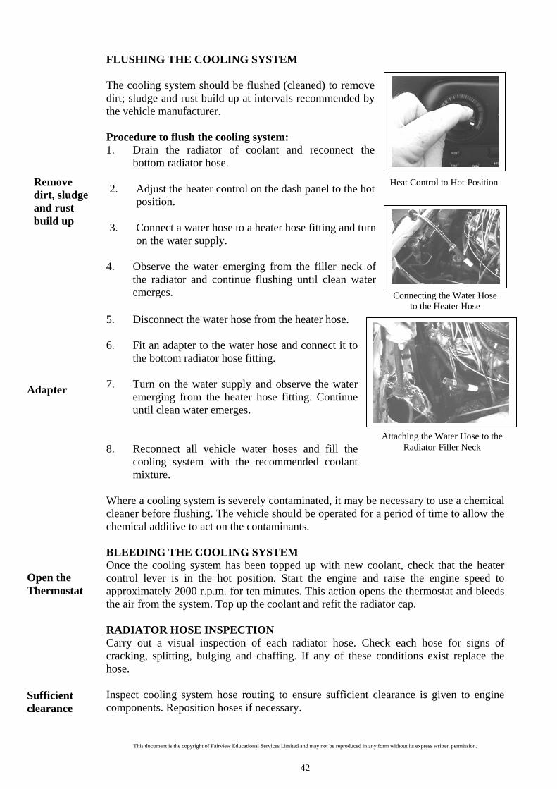
FLUSHING THE COOLING SYSTEM The cooling system should be flushed (cleaned) to remove dirt; sludge and rust build up at intervals recommended by the vehicle manufacturer. Procedure to flush the cooling system: 1. Drain the radiator of coolant and reconnect the
bottom radiator hose. 2. Adjust the heater control on the dash panel to the hot
position. 3. Connect a water hose to a heater hose fitting and turn
on the water supply. 4. Observe the water emerging from the filler neck of
the radiator and continue flushing until clean water emerges.
5. Disconnect the water hose from the heater hose. 6. Fit an adapter to the water hose and connect it to
the bottom radiator hose fitting. 7. Turn on the water supply and observe the water
emerging from the heater hose fitting. Continue until clean water emerges.
8. Reconnect all vehicle water hoses and fill the
cooling system with the recommended coolant mixture.
Where a cooling system is severely contaminated, it may be necessary to use a chemical cleaner before flushing. The vehicle should be operated for a period of time to allow the chemical additive to act on the contaminants. BLEEDING THE COOLING SYSTEM Once the cooling system has been topped up with new coolant, check that the heater control lever is in the hot position. Start the engine and raise the engine speed to approximately 2000 r.p.m. for ten minutes. This action opens the thermostat and bleeds the air from the system. Top up the coolant and refit the radiator cap. RADIATOR HOSE INSPECTION Carry out a visual inspection of each radiator hose. Check each hose for signs of cracking, splitting, bulging and chaffing. If any of these conditions exist replace the hose. Inspect cooling system hose routing to ensure sufficient clearance is given to engine components. Reposition hoses if necessary.
Remove dirt, sludge and rust build up
Adapter
Open the Thermostat
Sufficient clearance

This document is the copyright of Fairview Educational Services Limited and may not be reproduced in any form without its express written permission.
43
Very Important Safety Points
Squeeze each water hose for signs of internal crumbling. This may identify hoses that are deteriorating from the inside out. How to Replace a Radiator Hose 1. Drain the coolant from the radiator. 2. Loosen the securing clips from both ends of the faulty hose and remove the hose. 3. Transfer the clips to the new hose. 4. Refit the replacement hose into correct position and secure the hose clips. Refill
the radiator and check for leaks during engine operation.
DRIVE BELT CHECKS Drive belts should be checked regularly to ensure that they are in good working order. Carry out a visual inspection to check for signs of: Cracking Drive belts with cracks on the underside can create hinge points where flexing is excessive. A belt with cracks can break without warning. Glazing A glazed belt may slip in the pulleys and cause engine overheating. Underside Wearing The underside section of the belt may break off causing a rough running of the belt. Split belt Belt may appear slightly frayed but often the sidewalls are badly worn or the underside is split. Such belts may fall apart at any moment.
Check Hose Fittings for Coolant Leaks
Testing for Internal Hose Damage
SAFETY WHEN INSPECTING RADIATOR HOSES Wear protective clothing and eye wear. Beware of hot engine components. Ensure that the engine is switched off.
Secure hose clips
Carry out regular checks
Check Radiator Hose Clearance

This document is the copyright of Fairview Educational Services Limited and may not be reproduced in any form without its express written permission.
44
Loosen Alternator Pinch Bolt
Remove Drive Belt From Pulleys
Inspecting a Drive Belt
Greasy Belt The underside and sidewalls of the belt may be too slick as a result of grease softening. Aside from danger of slippage such belts fail rapidly. Drive belt tension should be checked regularly. A loose drive belt may slip and fail to rotate the water pump and cooling fan. This will result in the engine over-heating. Checking belt tension Apply moderate thumb pressure midway between the pulleys. The belt should deflect approximately 12-13 millimetres for a new belt and 13-14 millimetres for a used belt. Removal of fan belt 1. Loosen the alternator adjusting and mounting bolts
and move the alternator towards the engine.
2. Remove the drive belt from the pulleys, water pump,
alternator, and crankshaft. 3. Inspect the condition of the drive belt.
4. Carry out a visual check of each pulley alignment.
Checking Drive Belt Tension
Visual Check of Pulley Alignment
Removal procedure

This document is the copyright of Fairview Educational Services Limited and may not be reproduced in any form without its express written permission.
45
SAFETY WHEN CARRYING OUT DRIVE BELT CHECKS Ensure that the engine is switched off before making adjustments. Keep your hands away from moving drive belts. The belt can pull your
fingers into the pulleys, causing severe hand injuries. Be aware of hot engine components. Ensure that all tools are clean, dry and in good working order.
Spin Fan with Drive Belt Removed
Installing a Fan Belt Position the drive belt into the pulleys and adjust the belt tension. Tighten the adjusting and mounting bolts. COOLING SYSTEM FAN CHECK For vehicles fitted with a solid fan or flex fan it is important to check the condition of the fan blades and the mounting hub. Check for broken blades, cracked blades and mounting hub, and loose securing bolts. Should any of these conditions exist the fan should be replaced or secured immediately. For vehicles fitted with variable speed fans (thermostatic fan clutch or fluid coupling fan clutch) the following checks should be carried out: 1. Inspect the fan clutch hub for oil leaks. An oil leak could indicate a Silicone
leak from the fan clutch and would require fan clutch replacement.
2. With the ignition switched off, grasp the fan
blades opposite each other (3 o’clock and 9 o’clock) and try to move the fan or fan clutch assembly from side to side. Movement of more than 5 millimetres may indicate a worn clutch bearing or a worn water pump bearing. The unit should be replaced.
3. Run the engine to operating temperature and
then switch off the ignition. Spin the fan manually. If the fan rotates for more than two turns the fan clutch is freewheeling and the unit should be replaced.
Installing a Drive Belt
Check Fan Security- 3 O’clock and 9’O clock Position
Silicone leak?
Freewheeling
Very Important Safety Points
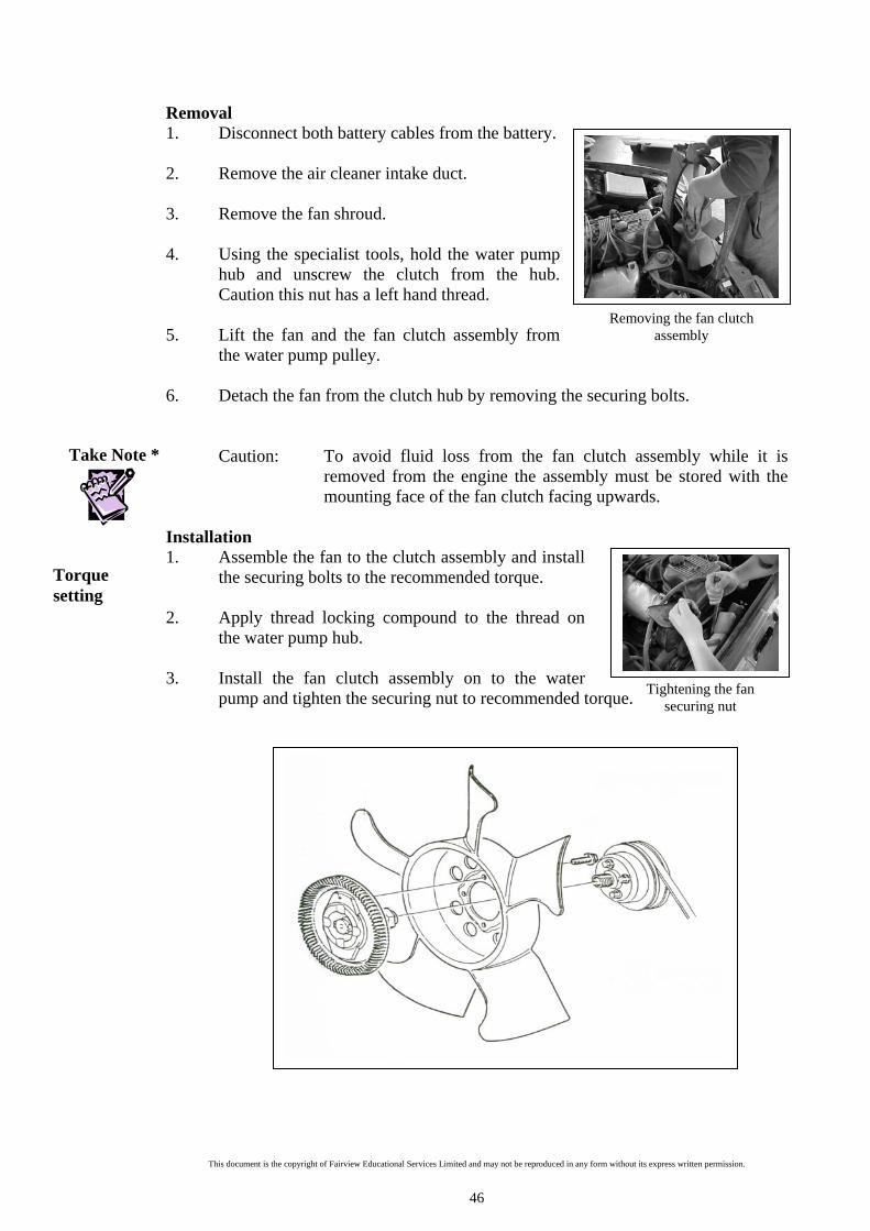
This document is the copyright of Fairview Educational Services Limited and may not be reproduced in any form without its express written permission.
46
Removing the fan clutch assembly
Tightening the fan securing nut
Removal 1. Disconnect both battery cables from the battery.
2. Remove the air cleaner intake duct. 3. Remove the fan shroud. 4. Using the specialist tools, hold the water pump
hub and unscrew the clutch from the hub. Caution this nut has a left hand thread.
5. Lift the fan and the fan clutch assembly from
the water pump pulley. 6. Detach the fan from the clutch hub by removing the securing bolts.
Caution: To avoid fluid loss from the fan clutch assembly while it is
removed from the engine the assembly must be stored with the mounting face of the fan clutch facing upwards.
Installation 1. Assemble the fan to the clutch assembly and install
the securing bolts to the recommended torque.
2. Apply thread locking compound to the thread on the water pump hub.
3. Install the fan clutch assembly on to the water pump and tighten the securing nut to recommended torque.
Take Note *
Torque setting

This document is the copyright of Fairview Educational Services Limited and may not be reproduced in any form without its express written permission.
47
Check Fan Security
Very Important Safety Points
For vehicles fitted with electric fans the following checks should be carried out: 1. Ensure that the electric motor is fitted
securely to the fan shroud and that the fan shroud is securely fitted to the radiator.
2. With the ignition switched off, grasp the fan
blades opposite each other (3 o’clock and 9 o’clock) and try to move the fan and clutch assembly from side to side. Movement of more than 5 millimetres may indicate a worn electric fan bearing. The unit should be replaced.
3. Ensure that there is sufficient clearance between
the fan blades and the radiator, and between the fan blades and the shroud.
4. Check that the fan blades rotate freely. 5. Ensure that all electric fan connections are clean
and secure. 6. Start the engine and run to normal operating
temperature. 7. Increase the engine speed to approximately 2000 r.p.m. The electric fan should
start up as the temperature rises above normal operating temperature. If the electric fan fails to operate consult the vehicle manual for further electrical tests.
Check Fan Clearance
SAFETY WHEN CARRYING OUT A COOLING SYSTEM FAN CHECK A fan with a cracked or bent blade is extremely dangerous. Broken
blades can be thrown out with great force, causing severe lacerations or death.
Be aware of hot engine components.
Keep hands and clothing clear of the rotating fan blades. The electric cooling fan is mounted behind the radiator and can start to operate at any time when the ignition switch is on. Care should be taken to ensure that the ignition is off when working in the fan area.
Worn electric fan bearing?
Secure connections

This document is the copyright of Fairview Educational Services Limited and may not be reproduced in any form without its express written permission.
48
Electric fan motor inspection 1. Verify that the battery is fully charged. 2. Disconnect the fan motor wiring plug. 3. Connect battery voltage and ammeter to the fan
motor wiring plug low-speed terminal. 4. Verify that the fan motor operates smoothly and
that the current draw is within manufacturer’s recommended range.
5. Connect battery voltage, an ammeter to the fan
motor wiring plug high-speed terminal. 6. Verify that the fan motor operates smoothly and
that the current draw is within manufacturer’s recommended range.
7. If the test results are outside of the manufacturer’s recommendations, replace the
fan motor. Electric fan motor removal 1. Disconnect the negative battery cable.
2. Disconnect the electric fan motor wiring plug.
3. Remove the electric fan shroud securing bolts and lift the fan and shroud
assembly from the radiator.
4. Remove the electric fan mounting bolts from the shroud. Electric fan motor installation 1. Align the electric fan with the shroud and secure the fan mounting bolts.
2. Align the fan shroud assembly with the radiator and secure the mounting bolts.
3. Reconnect the fan motor wiring plug.
4. Connect battery terminal.
5. Retest fan operation.
Current draw
Align fan and shroud
Component torque settings

This document is the copyright of Fairview Educational Services Limited and may not be reproduced in any form without its express written permission.
49
If the electric fan operation is not at fault, the next procedure is to check the fan relay operation Fan Relay Removal 1. Disconnect the negative battery cable. 2. Remove the fan relay from the main fuse box,
generally located in the engine bay. 3. Install the replacement relay. 4. Connect the negative battery terminal. 5. Test fan operation. Fan Relay Inspection 1. Check the continuity of the relay as shown in the diagram. 2. Apply battery voltage between terminals B and D. Check for continuity between terminals A and C.
Terminal Continuity A-C NO B-D YES
Engine bay
Continuity

This document is the copyright of Fairview Educational Services Limited and may not be reproduced in any form without its express written permission.
50
Checking Fan Movement to Test for Water Pump
Bearing Play and Noise
Using a Stethoscope to Listen to Bearing Condition when the
Engine is Running
Very Important Safety Points
CHECKING A WATER PUMP The following checks should be carried out when checking a water pump: 1. Inspect the water pump housing for coolant leaks
and if a leak is found, replace the water pump. 2. With the ignition switched off grasp the fan blades
opposite each other (3 o’clock and 9 o’clock positions) and try to move the fan blades from side to side. Movement of more than 5 millimetres may
indicate a worn water pump bearing. The unit should be replaced.
3. Check the security of the water pump mounting
bolts and the fan/pulley mounting bolts. 4. Check the drive belt tension to ensure that the
water pump is being driven correctly. 5. Start the ignition and use a stethoscope placed on
the water pump bearing to listen for a noisy water pump bearing. If this condition exists replace the water pump.
Securing Water Pump Mounting Bolts
3 o’clock and 9 o’clock positions
SAFETY WHEN CHECKING A WATER PUMP Wear protective clothing and eyewear. Be aware of rotating engine components. Be aware of hot engine components Ensure that tools are clean and dry and in good working order.
Drive Belt tension

This document is the copyright of Fairview Educational Services Limited and may not be reproduced in any form without its express written permission.
51
Removing a water pump assembly
Refitting a water pump
Removal of a water pump assembly 1. Drain the cooling system from both the
radiator tank and the engine block.
2. Release the fan belt adjusting bolt, slacken the alternator mounting bolt and remove the fan belt.
3. Remove the fan securing bolts and remove the fan from the water pump pulley.
4. Remove the water pump inlet hose and heater hose.
5. Remove the water pump securing bolts and remove the water pump from the engine block.
Water pumps are generally non-serviceable items and are replaced when faulty. However, some water pumps can be repaired but before making this decision the technician needs to examine the feasibility of carrying out the repair as opposed to replacement. If it is feasible to carry out a repair follow the manufacturers recommended procedures for the specific water pump. These procedures vary from water pump to water pump. Refitting a water pump 1. Ensure that both the water pump and engine block mating surfaces are clean and
free of gasket material. 2. Apply a thin continuous bead of sealant onto the water pump and engine block
mating surfaces. 3. Position a new water pump gasket on to the water pump mating surface and
align the water pump with the engine block. 4. Start by hand all water pump securing bolts.
Ensure that the water pump is correctly aligned before following the final torque sequence.
5. Refit the water pump drive pulley and fan. 6. Refit and tension the drive belt. 7. Fill the cooling system with the recommended coolant mixture. 8. Once the cooling system has been topped up with new coolant, ensure that the
heater control lever is in the hot position. Start the engine and raise the engine speed to approximately 2000rpm for ten minutes. This action opens the thermostat and bleeds the air from the system. Top up the coolant and refit the radiator cap.
Feasibility
Start by hand
Clean mating surfaces

This document is the copyright of Fairview Educational Services Limited and may not be reproduced in any form without its express written permission.
52
THERMOSTAT TESTING If a thermostat is stuck in the open or closed position damage to vehicle components may occur. A thermostat stuck in the open position allows the coolant to enter the radiator before the engine has reached its optimal operating temperature. This may result in: Poor engine performance and efficiency. Longer engine warm up period. Poor fuel economy. Contaminated lubrication oil. A thermostat stuck in the closed position prevents the coolant from entering the radiator and results in engine over-heating. This may lead to: Damage to engine components. Engine seizure. Thermostat Testing Test equipment required: Thermostat Thermometer Container of coolant A means of heating the coolant A piece of wire 1. Suspend the thermostat in the coolant so that it does not touch the container
surfaces. 2. Slightly warm the coolant. 3. When the thermostat opens slightly, push a piece of wire between the valve and
its seat. 4. Remove the thermostat from the coolant and allow to cool until the wire is held
tight by the valve. Note the operating temperature for the thermostat (usually stamped on the valve of the thermostat).
5. Place a thermometer in the container. 6. Immerse the thermostat again in the coolant holding the
wire and suspending the thermostat. As soon as the thermostat starts to open it will drop off the end of the wire. This is known as the crack open setting. 1. Immediately note the reading on the thermometer, the
reading should be between ± 2°C of that stamped on the valve.
2. Use the wire to suspend the thermostat again.
Note the temperature at which the thermostat opens fully. The reading should be between 8-10°C above the stamped reading. An Open Thermostat
Over cooling
Over heating
Crack open setting
A Closed Thermostat
Valve and seat
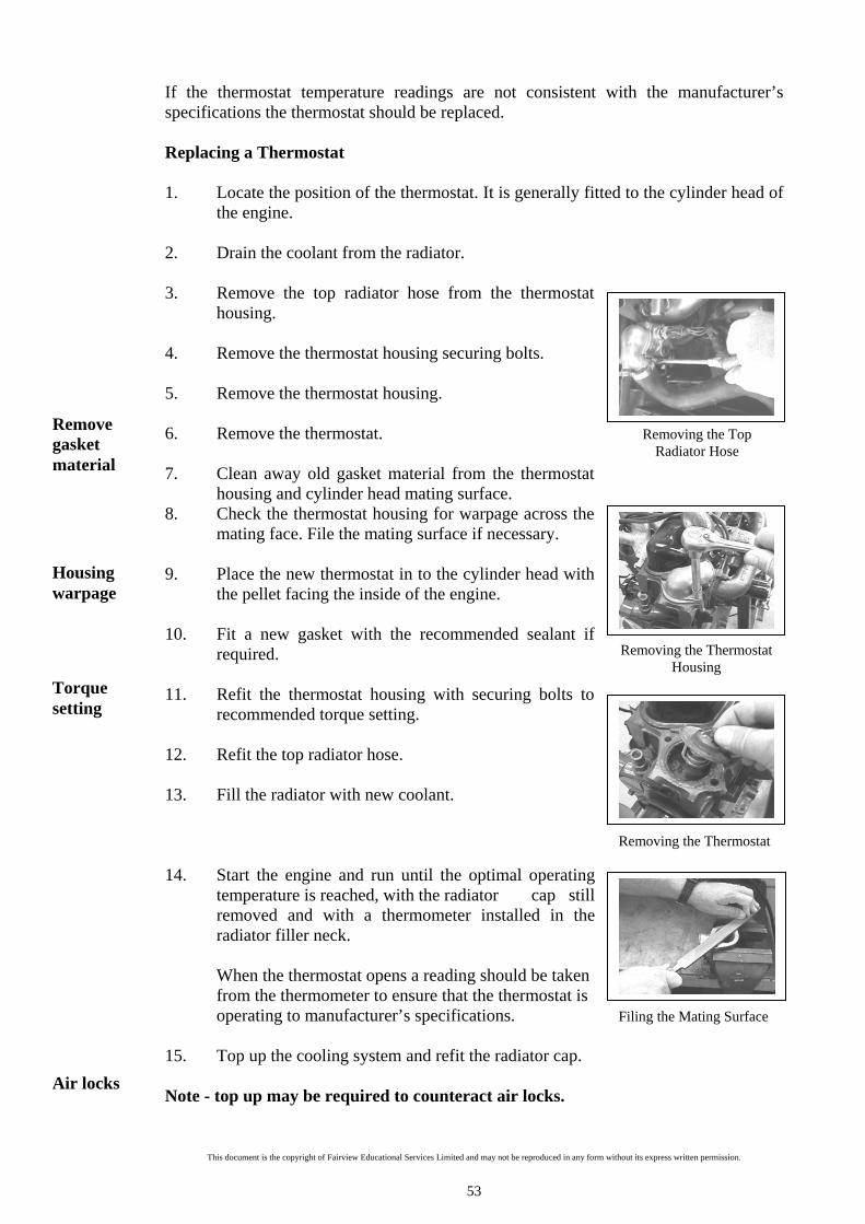
This document is the copyright of Fairview Educational Services Limited and may not be reproduced in any form without its express written permission.
53
Removing the Top Radiator Hose
Removing the Thermostat Housing
Removing the Thermostat
If the thermostat temperature readings are not consistent with the manufacturer’s specifications the thermostat should be replaced. Replacing a Thermostat 1. Locate the position of the thermostat. It is generally fitted to the cylinder head of
the engine. 2. Drain the coolant from the radiator. 3. Remove the top radiator hose from the thermostat
housing. 4. Remove the thermostat housing securing bolts. 5. Remove the thermostat housing. 6. Remove the thermostat. 7. Clean away old gasket material from the thermostat
housing and cylinder head mating surface. 8. Check the thermostat housing for warpage across the
mating face. File the mating surface if necessary. 9. Place the new thermostat in to the cylinder head with
the pellet facing the inside of the engine. 10. Fit a new gasket with the recommended sealant if
required. 11. Refit the thermostat housing with securing bolts to
recommended torque setting. 12. Refit the top radiator hose. 13. Fill the radiator with new coolant. 14. Start the engine and run until the optimal operating
temperature is reached, with the radiator cap still removed and with a thermometer installed in the radiator filler neck.
When the thermostat opens a reading should be taken from the thermometer to ensure that the thermostat is operating to manufacturer’s specifications.
15. Top up the cooling system and refit the radiator cap. Note - top up may be required to counteract air locks.
Filing the Mating Surface
Remove gasket material
Housing warpage
Torque setting
Air locks

This document is the copyright of Fairview Educational Services Limited and may not be reproduced in any form without its express written permission.
54
Striking a drift to dislodge a welsh plug
Removing a welsh plug using pliers
Installing a welsh plug
CHECKING WELSH PLUGS It may be necessary to use a lead light and mirror to inspect welsh plugs as it likely that they may be obscured by engine components. Welsh plugs should be checked for signs of: Coolant leakage Rusting Bulging Not flush with cylinder block Should any of these conditions be present, replace the welsh plug. Removal of a welsh plug 1. Allow the engine to cool and drain the cooling
system. 2. Position a drift at the bottom end of the welsh
plug and strike the drift with a hammer to dislodge the welsh plug.
3. Grasp the dislodged welsh plug with a pair of
pliers and remove from the cylinder block. 4. Inspect the internal surface of the water jacket
passage for evidence of sludge and scale build up. Using a scrapper, dislodge any sludge or scale build up to allow for removal during cooling system flushing.
Installing a welsh plug 1. Ensure that the cylinder block casting holes are free from rust and scale build up. 2. Select a suitable drift to install the new welsh
plug. The drift should be slightly smaller in diameter than the inside diameter of the welsh plug. This provides support and ease of manoeuver when installing the welsh plug and removing the drift.
3. Apply sealant to the surfaces of the welsh plug
and the cylinder block. 4. Align the plug squarely into the cylinder block and using a hammer strike the
drift to secure the welsh plug into the correct position. 5. Flush the cooling system. 6. Carry out a cooling system pressure test.
A Cylinder Block Welsh Plug
Drift
Sealant
Sludge and scale

This document is the copyright of Fairview Educational Services Limited and may not be reproduced in any form without its express written permission.
55
Removing sender Wire Connection
Attaching the Jump Wire
Observing the Hot Reading
Observing the Cold Reading
Temperature Sender unit
Jumper wire
Hot zone
Cold zone
TESTING A TEMPERATURE GAUGE Prior to carrying out a temperature gauge test ensure that the vehicle manual is consulted as damage may occur to the temperature gauge on some vehicles.
1. Ensure that the ignition is switched off. 2. Locate the temperature sender unit; it is generally
found next to the thermostat housing on the cylinder housing.
3. Remove the electrical wire from the temperature
sender unit and attach it to a jumper wire. 4. Attach the other end of the jumper wire to a ground
source on the engine. 5. Switch on the ignition. The temperature gauge needle
should move to the extreme point on the hot zone.
6. Disconnect the ground wire and observe the
temperature gauge needle. The needle should move to the extreme point on the cold zone.
If the temperature gauge needle does not respond as outlined, the most likely explanations include: A damaged temperature gauge. A faulty wiring circuit between the sender unit and the temperature gauge. A faulty sender unit.
Consult vehicle manual

This document is the copyright of Fairview Educational Services Limited and may not be reproduced in any form without its express written permission.
56
Coolant leakage External Possible causes Remedy A. Loose hose clips or faulty hoses Tighten hose clips or renew faulty
components. B. Leaking radiator core or tanks Repair or renew radiator C. Worn or damaged water seal assembly Renew seal assembly D. Worn or damaged water pump bearing assembly
Renew water pump bearing and shaft assembly
E. Loose or rusted expansion plugs. Renew faulty components F. External crack in cylinder block or head.
Renew faulty components.
G. Faulty cylinder head gasket or loose holding down bolts.
Renew gasket and correctly tighten cylinder head bolts.
H. Leak at thermostat cover and/or water pump joint gasket.
Rectify leaks.
Coolant leakage Internal Possible causes Remedy A. Crack in cylinder bore wall Renew cylinder block. B. Crack in cylinder head, combustion chambers or valve ports.
Renew cylinder block.
C. Cylinder head cracked and leaking into valve rocker compartment
Renew cylinder head.
D. Cracked cylinder block water jacket, leaking into engine tappet compartment.
Renew cylinder block.
E. Cylinder head gasket due to warped head.
Reface cylinder head and renew gasket.
Coolant loss by overflow Possible cause Remedy A. Over-full system. Check and refill to 1” below filler neck B. Faulty pressurised radiator cap. Renew faulty cap. C. Blocked radiator core tubes. Clean or renew radiator core D. Coolant foaming due to poor quality anti-freeze or corrosion inhibitor.
Drain system and renew coolant and additive.
Engine overheating Possible causes Remedy A. Obstructed air passages through radiator core from front to rear.
Blow out obstruction from rear to front of radiator core with compressed air or water pressure.
B. Incorrect ignition timing. Check and reset timing. C. Incorrect valve timing. Check and reset valve timing. D. Low engine oil level. Stop engine immediately, and replenish oil
in pump. E. Engine tight after overhaul. Check and if satisfactory, stop engine and
allow to cool out. F. Poor circulation. Check and rectify
COOLING SYSTEM TROUBLESHOOTING CHART

This document is the copyright of Fairview Educational Services Limited and may not be reproduced in any form without its express written permission.
57
G. Loss of coolant due to overflow. Check and rectify H. Faulty thermostat. Renew thermostat I. Restricted muffler or tail pipe, accompanied by a loss of power.
Remove restriction or renew components
J. Incorrectly adjusted or dragging brakes. Check and rectify by adjustment or renewal of components
Coolant circulation faulty Possible causes Remedy A. Partial blockage of radiator core tubes. Clean out or renew radiator core. B. Water sludge deposits in engine water jacket.
Clean and flush engine jacket and add rust inhibitor to coolant.
C. Fan belt broken or slipping. Renew and adjust fan belt. D. Faulty water pump or thermostat. Overhaul or renew water pump, renew
thermostat. E. Collapsing lower radiator hose. Check and renew lower radiator hose and
check radiator core tubes. F. Insufficient coolant in system Replenish coolant. ROAD TEST To complete the cooling system service the vehicle will need to be tested on the open road. Monitor the temperature gauge throughout the road test to ensure it reads within the normal temperature operating range. Listen for the noise of the electric fan switching on and off. Once the road test is complete, check the underside of the vehicle for signs of coolant leakage, if evident repair immediately. Clean the vehicle in preparation for customer delivery and ensure protective guards, safety features and cowlings are in place. Complete job card and relevant service documentation.
SECTION OVERVIEW To operate efficiently cooling systems require regular servicing. It is important to observe all safety procedures when carrying out any cooling system service check. Before attempting to carry out a service check ensure that: Service instructions are read and understood. The vehicle manual is consulted. The correct tools are chosen for each task. Protective clothing is worn.
Key Points
Monitor gauge

This document is the copyright of Fairview Educational Services Limited and may not be reproduced in any form without its express written permission.
58
REVIEW QUESTIONS THREE Q31 Complete the following sentence:
It is necessary to _______________ the manufacturer’s______________ when replacing the _________________ mixture. The reason for this is that vehicles __________________ in _______________ climate _________________ and the _________________ of anti-freeze that is used is ________________ on the temperature at which the vehicle operates.
Q32 Explain how you should check the operation of a thermostatic fan clutch.
________________________________________________________________
________________________________________________________________
________________________________________________________________
________________________________________________________________ Q33 What is the purpose of carrying out a cooling system pressure test?
________________________________________________________________
________________________________________________________________
________________________________________________________________ Q34 Name six common leak sources from the cooling system.
________________________________________________________________
________________________________________________________________
________________________________________________________________ Q35 What do the manufacturer’s recommended pressure ratings indicate for a
radiator?
________________________________________________________________

This document is the copyright of Fairview Educational Services Limited and may not be reproduced in any form without its express written permission.
59
Q36 Complete the following sentence: Attach the pressure testing equipment to the ________________ filler neck.
______________ up the pressure tester to the ___________________ recommended pressure __________________. Q37 List four engine faults that may occur if the thermostat is stuck in the open
position.
________________________________________________________________
________________________________________________________________
________________________________________________________________
________________________________________________________________ Q38 Outline the test procedure to follow when testing a thermostat.
________________________________________________________________
________________________________________________________________
________________________________________________________________
________________________________________________________________ Q39 In which direction should a thermostat be placed into a cylinder head?
________________________________________________________________ Q40 Why should corrosion inhibitor be added to coolant?
________________________________________________________________
________________________________________________________________ Q41 Where is the heater temperature control lever normally located on a vehicle?
________________________________________________________________

This document is the copyright of Fairview Educational Services Limited and may not be reproduced in any form without its express written permission.
60
Q42 Name four conditions that will require a radiator hose to be replaced.
________________________________________________________________
________________________________________________________________
________________________________________________________________
________________________________________________________________ Q43 How should a radiator hose be checked for signs of internal crumbling?
________________________________________________________________
________________________________________________________________
________________________________________________________________ Q44 How should dirt build up be removed from radiator fins?
________________________________________________________________
________________________________________________________________ Q45 What are the likely results of a loose drive belt?
________________________________________________________________ ________________________________________________________________
________________________________________________________________
Q46 What would a fan blade movement of more than 5 millimetres indicate?
________________________________________________________________
________________________________________________________________ Q47 Why is it necessary to bleed the cooling system?
________________________________________________________________
________________________________________________________________

This document is the copyright of Fairview Educational Services Limited and may not be reproduced in any form without its express written permission.
61
Q48 Explain in your own words the procedure to follow when flushing the cooling system.
________________________________________________________________
________________________________________________________________
________________________________________________________________
________________________________________________________________
________________________________________________________________
Q49 What does the specific gravity of coolant indicate?
________________________________________________________________
________________________________________________________________ Q50 Explain how you should test the specific gravity of coolant.
________________________________________________________________
________________________________________________________________
________________________________________________________________ Q51 Complete the following sentence: With the engine switched off ____________ the fan blades _______________ each other (3 o’clock and ____________ positions), and try to ___________
the fan blades from side to side. Movement of more than ________________ would _____________ a worn water pump ________________.
Q52 Name three effects over cooling can have on an engine
________________________________________________________________
________________________________________________________________
________________________________________________________________

This document is the copyright of Fairview Educational Services Limited and may not be reproduced in any form without its express written permission.
62
COOLING SYSTEM WORD SEARCH
T A T S O M R E H T
N Z N P W C A I Y A
A O R R H V D N A C
L L I E D C I H S M
O D O S L C A I C P
O C V S O F T B C C
C X R U F R O I I W
M W E R I B R T F V
H T S E N G S O I D
M V E N A I D R C V
X X R S M N D N E L
O B K O E E M O P D
M E N U E D C U S Z
T L Q E F K T Z H G
Identify the following words in the word search above:
Coolant Corrosion Gasket Inhibitor Manifold
Pressure Reservoir Specific Radiator Thermostat
Identify the automotive terms scrambled below:
AERPUTMTERE ________________________________________________
AKJTEC ________________________________________________
DOLRES ________________________________________________
GYTVIRA ________________________________________________
RTSOF ________________________________________________
This document is the copyright of Fairview Educational Services Limited and may not be reproduced in any form without its express written permission.
63
ELEMENTS AND PERFORMANCE CRITERIA – AURTTC001
ELEMENT NAME
Prepare to inspect and service cooling system. AURTTC001.1
1.1 Job requirements are determined from workplace instructions.
1.2 Servicing information is sourced and interpreted.
1.3 Hazards associated with the work are identified and risks are managed.
1.3 Tools, equipment and materials are selected and checked for serviceability.
ELEMENT NAME
Inspect cooling systems. AURTTC001.2
2.1 Inspection is carried out according to manufacturer specifications, workplace procedures, and safety and environmental requirements.
2.2 Inspection results are compared with manufacturer specifications.
2.3 Inspection findings are reported according to workplace procedures, including recommendations for necessary repairs or adjustments.
ELEMENT NAME
Service cooling systems AURTTC001.3
3.1 Service and adjustments are carried out according to manufacturer specifications, workplace procedures, and safety and environmental requirements, and without causing damage to components or systems.
3.2 Post-service testing is carried out according to workplace procedures.
ELEMENT NAME
Complete work processes. AURTTC001.4
4.1 Final inspection is made to ensure work is to workplace expectations and vehicle or equipment is presented ready for use.
4.2 Work area is cleaned, waste and non-recyclable materials are disposed of, and recyclable material is collected.
4.3 Tools and equipment are checked and stored according to workplace procedures.
4.4 Workplace documentation is processed according to workplace procedures
473 Te Rapa Road. PO Box 10-244, Hamilton 3241
phone 07 849 9828 | fax 07 849 9808 | [email protected] | www.feds.co.nz
Accredited and registered provider
EDUCATIONAL SERVICES LTD