edr5018
DESCRIPTION
raychemTRANSCRIPT


EDR-5018Rev 5 11/6/96
1
EDR # 5018 Original Issue Date: 3/20/80
REVISION RECORDRev. Page Paragraph Description Date
5
5
5
5
5
5
5
2
10
11
11
11
12
14
Item 1.2.2
Item 3.2.2.1
Item 3.2.2.2
Item 3.2.2.3
Item 3.2.2.4
Item 3.2.3
Figure
Added paragraph “In 1996,.....the original 74oC (see 3.2.3)
Added paragraph “In the 1996 testing,....135 specimens.”(see ref. 15206-14)
Added paragraph “In 1996, ....temperatures of 135oC and120oC.”
Added paragraph “In 1996,.....ultimate elongation at2”/min.”
Added paragraph “In 1996,......elongation was determined.”
Added 1996 data to Table 3 and modified table titles
Added 1996 data to figure
11/6/96
11/6/96
11/6/96
11/6/96
11/6/96
11/6/96
11/6/96
Approvals (Type and sign name)
Rev. Date Tested By Prepared By Product Mgmt. Tech. Oper.5 11/6/96 Kathy
MaherKathy Maher Bernard de Brunier

EDR-5018Rev 5 11/6/96
CONTENTS
1. FOREWORD
1.1 Summary
1.2 An Overview of Presented Results
1.3 Conclusions
2. CONSIDERATIONS IN DEFINING PROSPECTIVE LIFE
2.1 General
2.2 Thermal Rating
2.3 Emergency Rating
2.4 Short Circuit Rating
2.5 Electrical Factors
2.6 Normal and Abnormal Service Conditions
3. MATERIALS TESTS
3.1 Thermal Endurance of Red Non-Tracking Material (HVTM)
3.2 Thermal Endurance of Stress Control Material
3.3 Stability to Weather Conditions
4. PRODUCT TESTS
4.1 Overview
4.2 Test Data Relative to Corona and Load Cycling of Terminations
4.3 Test Data Relative to Overvoltage Life
4.4 Data Regarding Life in Polluted Test Sites
REFERENCES
APPENDIX A
Discussion of Normal Operating Conditions
APPENDIX BThermal Analysis of a Cable Termination

EDR-5018Rev 5 11/6/96
Page 1A LIFE ASSESSMENT OF RAYCHEM
HEAT SHRINKABLE HIGH VOLTAGE TERMINATIONS
1. FOREWORD
1.1 Summary
There is no specification which can be used to predict the service life of a power cabletermination. The design factors involved are complex including parameters such asenvironmental conditions, applied voltage, pollution level, operating and ambienttemperature, and loading conditions. The synergistic effects of such parameters woulddefeat the best computer algorithm.
In determining our statement of life, this report presents results and discusses thesignificance of the following factors:
1.1.1 Thermal stability of the materials used in the terminations.
1.1.2 Weathering stability of the materials used in the terminations.
1.1.3 Load cycling tests on the terminations.
1.1.4 Overvoltage tests on the terminations.
1.1.5 Accelerated tests in various working environments.
Normal, abnormal and emergency operating conditions on the terminations have alsobeen considered.
The conclusions stated below are based on our best engineering judgement using thedata presented.
1.2 An Overview of the Presented Results
1.2.1 Thermal Endurance of Red Non-Tracking Material (HVTM)The Arrhenius data shows that this material can be rated at 90oC for 40 yearswith a retention of 100 percent ultimate elongation (see 3.1.2.1). As discussed inthe text this end point is extremely conservative.
1.2.2 Thermal Endurance of Stress Control Material (SCTM)SCTM can have a lower rated temperature than that of HVTM or the cableinsulation because the SCTM does not contact the conductor or lug. Afteranalyzing the total data presented we have concluded that the thermalendurance of SCTM provides the overall design life limit of the indoorterminations. The data can be interpreted in several ways

EDR-5018Rev 5 11/6/96
Page 2
depending on the customer operating conditions. The life predictions shown instatements 1.3.1 are based on this data. These predictions are based onArrhenius plots using a retention of 20 percent ultimate elongation, aconservative limit considering typical high voltage cable applications (see 3.2.1).
In 1996, a limited thermal endurance test was performed on SCTM tubing whichwas manufactured from the same raw materials except for the sourcing of theraw materials. An endpoint of 25% ultimate elongation was chosen. The resultsof the limited thermal endurance indicate that the 40 year lifetime of the currentSCTM tubing is 79oC rather than the original 74oC (see 3.2.3).
1.2.3 Weathering Data of HVTMAnalysis of the data presented shows that the material will retain more than 100percent ultimate elongation after 30 years in sunlight equivalent to that ofPhoenix, Arizona. The material will give better physical performance in moretemperate zones. Indoor terminations will not be limited by these test results.
1.2.4 Load Cycling Tests on the Installed TerminationsThe data presented shows corona (partial discharge) stability far in excess ofany known specification requirements. Overvoltage life analysis of the loadcycled samples shows that the termination performance is well abovespecification requirement after the equivalent of 16.2 years. The overvoltagetests outlined in 1.2.5 indicate life extrapolation to 40 years is not unreasonable.
1.2.5 Overvoltage Life TestsThe data presented shows a calculated minimum termination life of 5,000 yearswhen subjected to overvoltage testing.
1.2.6 Accelerated Testing on Outdoor Test SitesRaychem has used six monitored test sites to assess termination life. Resultsfrom these sites, whilst not completely comprehensive, show no evidence thatthe life outdoor terminations will be less than thirty years.
1.3 Conclusions
Based on the data presented, specifically the parameters discussed in Section 1.1, thefollowing assessment is made.
This life assessment is made assuming that the reader requires the terminations to becompatible with the cable (XLPE is normally rated at 90oC maximum conductor normaloperating temperature) and installed in equipment which may have a life expectancy of40 years. Operating conditions such as load cycling and maximum ambient will affectthe life statement; hence several assumptions have been made and the life predictedbased on those assumptions. Clearly increasing the maximum operating temperature ofthe cable conductor will reduce the life, and reducing the maximum operatingtemperature would correspondingly increase the life.

EDR-5018Rev 5 11/6/96
Page 3
1.3.1 Indoor Terminations (Type HVT-I-XXX and NHYT-I-XXX. Data presented does not include exposure to radiation environment.)
1.3.1.1 40 years at 90o maximum operating condition for the cable conductor.
Assumptions made:
The load will cycle in a manner no worse than that described in AppendixA. SCTM operates approximately 10oC cooler than cable conductor, asdescribed in Appendix B.
1.3.1.2 40 years at 86.5oC maximum operating condition for the cable conductor.
Assumptions made:
The ambient does not exceed 40oC, load is continuous for 40 years.
1.3.1.3 40 years at 81oC maximum operating condition for the cable conductor.
Assumptions made:
The ambient does not exceed 55oC, load is continuous for 40 years.
1.3.1.4 40 years at 85oC maximum operating condition for the cable conductor.
Assumptions made:
The ambient does not exceed 51.8oC, load is continuous for 40 years.
1.3.1.5 40 years at 90oC maximum operating conditions for the cable conductor.
Assumptions made:
The ambient does not exceed 37.4oC, load is continuous for 40 years.
1.3.1.6 29.4 years at 90oC maximum operating condition for the cable conductor.
Assumptions made:
Ambient does not exceed 40oC, load is continuous for 29.4 years(AIEE #1).

EDR-5018Rev 5 11/6/96
Page 4
1.3.1.7 27.2 years at 85oC maximum operating condition for the cable conductor.
Assumptions made:
The ambient does not exceed 55oC, load conditions continuous for 27.2years (AIEE #1).
1.3.1.8 40 years at 74oC continuous operating SCTM temperature.
1.3.1.9 5.7 years at 90oC continuous operating SCTM temperature.
1.3.2 Outdoor Terminations
A life of at least 30 years can be expected based on weathering data of HVTM. The lifemust be derated if the operating conditions limit the performance requirements to theassumptions made in statements 1.3.1.6, 7 or 9 above.
2. CONSIDERATION5 IN DEFINING PROSPECTIVE LIFE
2.1 General
The manufacturer generally uses a testing technique during development which is bestunderstood by analogy to a ladder. Once a material is tentatively selected, it must besubjected to a series of tests to determine its suitability for its intended service. Thisseries of tests is the first rung on the ladder. One of these tests is thermal aging.Another is an examination of the effects of various environmental factors expected inservice on the mechanical and electrical properties of the material.
Once the results of this series of tests indicates the material to be a good candidate, thestage is set for the second step which is the testing of the combination of materials in aninsulation system (the product). Product tests are functional tests and realistic criteriamust be used to define failure. Stability of the corona extinction voltage (CEV) is aprimary requirement. Standardized design tests are used for product testing whereverpossible. Special tests are devised whenever no standardized test covers adequately aservice requirement.
The testing ladder is an idealized concept. In real time the completion of thermal agingtests on the materials may take several years, especially if demonstration of complianceto a 40-year life requirement is involved.
The selected end points must be realistic. For instance, since Raychem's red highvoltage non-tracking material (HVTM) is in contact with the lug, the life of this material

EDR-5018Rev 5 11/6/96
Page 5
must be adequate at the temperature of the lug, which is close to but below the ratedconductor temperature. The stress control material, however, is not in contact with thelug or conductor and it is important to select a realistic temperature for examining theprospective thermal life of this material. This temperature will obviously be somewhatless than rated conductor temperature.
2.2 Thermal Rating
The thermal rating of an electrical apparatus is that temperature which corresponds tothe sum of the highest expected service ambient temperature and the temperature riseexpected under full load operation (2). In order to qualify for a thermal rating, data arerequired to demonstrate that the life is equal or better than that of equipment which hasoperated successfully for many years. Oven aging tests at various temperatures areperformed and data on times to a preselected "failure" point are collected and analyzedstatistically. An Arrhenius plot is made, and the plot is extrapolated to the desired ratedtemperature. IEEE #1 and #98 (3,4) are guides which define how accelerated ovenaging tests should be made and how the results should be treated mathematically toproduce an Arrhenius plot. The statistical aspects of such testing are defined inreference 5.
2.3 Emergency Rating
According to reference one, "Operation at the emergency overload temperature of130oC (as is required of XLPE and EPR cables with a 90oC rating) shall not exceed 100hours in any twelve consecutive months nor more than 500 hours during the life of thecable." It is important to determine the stability of the insulation system when subjectedto overload conditions.
2.4 Short Circuit Rating
The short circuit rating of a crosslinked polyethylene cable is that current which, whenapplied for specified time (6, 7), produces a conductor temperature of 250oC andintense short circuit forces. Since the operation of breakers isolates the faulted circuitfrom the source in a time which is normally less than 2 seconds, the thermal mass of thecable limits the average temperature rise to a relatively small value. The effect of thistemperature rise on termination life is considered small and negligible and therefore noconsideration of this is included in this report.
2.5 Electrical Factors
2.5.1 Design tests (8) are consensus judgements on tests required to demonstratequalification for operation under system conditions. The details of how Raychemterminations relate to these requirements are published elsewhere (9). All the

EDR-5018Rev 5 11/6/96
Page 6
tests (ac withstand, lightning and switching impulse, wet withstand, dc withstand andCEV) relate to system requirements which are essential to insulation coordination aswell as providing assurance of adequate safety factor against failure under a number ofpossible system conditions.
2.6 Normal and Abnormal Service Conditions
2.6.1 Normal Service Conditions
Aside from the electrical factors above, reference 8 specifies ambient temperature andaltitude levels. When the installation is in an enclosure, the maximum ambient is 55oC(and the conductor 85oC). Otherwise, the ambient is 40oC (and the conductor may be atthe 90oC rated temperature). The minimum ambient is -30oC. The Maximum Altitude is1000 meters (3300 ft.). Equipment rarely operates at rated temperature for its designlife. This is discussed in Appendix A.
2.6.2 Non-Standard Conditions
Any condition outside the above range is considered nonstandard. Examples are: (8)
(a) Ambient temperatures less than -30oC and more than +40oC.
(b) Altitude exceeding 1000 meters (3300 ft.) where atmospheric air is part of thethermal and/or dielectric system.
(c) Damaging fumes or vapors, excessive or abrasive dust, explosive mixtures of dustor gases, steam, salt spray, excessive moisture or dripping water, etc.
(d) Unusual mechanical conditions such as: vibration, shock, cantilever loading, windloading, icing, etc.
3. Materials Tests
3.1 Thermal Endurance of Red Non-Tracking Material (HVTM)
Thermal endurance tests were made on two batches labeled A and B.
3.1.1 Test Details
3.1.1.1. Specimens
Dumbbell tensile specimens were cut from injection molded slabs to be not closer than25mm to the edge of the slab. The specimens were then randomized before heattreatment.

EDR-5018Rev 5 11/6/96
Page 7
3.1.1.2 Heat Treatment
The specimens were mounted in aging ovens to be clear of any oven wall by at least 3inches and heat aged at the following temperatures: 250oC, 230oC, 210oC, 190oC, 170oC,150oC, and 135oC.
3.1.1.3. Sampling
Five specimens were removed from the oven at selected times of aging.
3.1.1.4 Measurements
Decay curves of average ultimate elongation against time of exposure were drawn andthe time required for the elongation to fall to 100 percent was determined. The standarddeviation of the elongation data was calculated. This was converted into a standarddeviation on time by multiplying by the negative inverse of the slope of the decay curve.
3.1.2 Test Results
3.1.2.1. Ultimate elongation was chosen partly because it is a functional property andpartly because its value decreases monotonically with aging time. A level of l00 percentelongation was chosen partly to limit the required aging time, and partly because at l00percent elongation a very large safety factor with respect to the elongation produced byany conceivable flexure of the termination in usage exists. Actually from the flexurestandpoint, even l0 percent would be adequate. However, in consideration of therequirement that the material be resistant to localized surface discharges in moistconditions, a safety factor was considered advisable even though no data exists whichindicates that the resistance to surface tracking decreases with age. To the contrary,available data show that at least down to l00 percent elongation, no loss in resistance tosurface tracking exists.
3.1.2.2. The mean values of the aging times to reach 100 percent ultimate elongation atthe various temperatures are shown in Table 1 and on Figure 1. 95 percent confidencelimits on the means were calculated. These values are also plotted on Figure 1 as barsabove and below the points. Due to lack of specimens, no elongations less than

EDR-5018Rev 5 11/6/96
Page 8
100 percent could be obtained at 135oC. The point in the table and plot was obtained byextrapolation from higher elongations to 100 percent, and confidence limit estimateswere omitted.
TABLE 1Hours to 100% Elongation
Temperature A B250 2.8 3.6230 6.9 8.1210 35 34190 120 120170 640 620150 1920 2250135 6700 7000
3.1.3 Analysis of Data
According to specifications (3, 10, 11) the exposure temperatures shall be selected sothat the highest temperature gives a life of at least 100 hours and the lowesttemperature gives a life of at least 5000 hours. This eliminates temperatures above190oC from consideration. The lives at the four remaining temperatures were subjectedto at least squares regression analysis to derive the intercept and slope values. Thelines on Figure 1 are drawn to fit these values.
The predicted hours are at 90oC.Group A 412,762 hours = 47 yearsGroup B 506,407 hours = 58 years
3.1.4 Conclusions
Since the product in service will never experience elongations exceeding a few percent,the prognosis that the product made from this material will live more than 40 years at arated temperature of 90oC is considered extremely conservative.

EDR-5018Rev 5 11/6/96
Page 9

EDR-5018Rev 5 11/6/96
Page 10
3.2 Thermal Endurance of Stress Control Material
3.2.1 The results of an oven aging test program will be given here in order to indicatethe effect of thermally induced degradation on projected life. It is important to note thatstability to electrical and thermal stress are also important. Test programs have beenrun to determine these factors and the results are in the open literature (12). In essencethese tests show:
1. Effect of stress at room temperature on electrical properties. Result: Nomeasurable effect at stresses as high as 20kV/cm for times up to 20,000 hours.
2. Effect of temperature of SCTM on electrical properties. Result: Effect is barelymeasurable from room temperature to 125oC.
3. Effect of time at 50oC and 100oC on electrical properties. Result: A slight,insignificant drop in impedance for times to 20,000 hours. More drop occurred at100oC than at 50oC.
4. Effect of load cycling [150 load cycles to 95oC conductor temperature (5 hourson/3 hours off)] on electrical properties of SCTM. Result: Capacitance of SCTMincreases slightly (1.4 to 2.0 pf/cm) while dissipation factor of SCTM drops from0.284 to 0.235 and then is restored to 0.284.
These tests show that the electrical properties of SCTM are stable under conditionssimilar to those met in the field. In the following test program, the 20 percent elongationpoint has been chosen as describing an "end of life" characteristic. 100 percentelongation was chosen for HVTM. If mechanical requirements alone were considered,20 percent would have been chosen for both, for in the application, the amount offlexure of cable terminations is very small, corresponding to a maximum of 10 percent.However, the SCTM is protected while the HVTM is not. Moreover, the surface of theHVTM is subjected to leakage currents and it is important to require that the materialretain a larger percent elongation at least until data are available to show that it is notrequired.
3.2.2 Test Details
3.2.2.1. Test Specimens for Mechanical Testing
SCTM tubing (41/21 size) was fully recovered by placing in a 150oC oven for 10minutes. 200 dumbbell tensile specimens were cut from this tubing, and randomized bytumbling.
In the 1996 testing, SCTM tubing (42/19 size, EW42821) was tested using the samesample preparation and cutting only 135 specimens (see ref. 15206-14)

EDR-5018Rev 5 11/6/96
Page 11
3.2.2.2. Aging
The 200 specimens were hung in four circulating air ovens at temperatures of 135o,120o, 105o and 100oC.
In 1996, the specimens were hung in two air circulating ovens at temperatures of 135 oCand 120 oC,
3.2.2.3. Sampling
For mechanical testing, at predetermined aging times, five samples were removed froman oven and tested for ultimate elongation at 100mm/min.
In 1996, the five samples were removed from the oven and tested for ultimateelongation at 2”/min.
3.2.2.4. Calculations
Arithmetic means and 95 percent confidence limits on ultimate elongation arecalculated.
Plots on elongation versus aging time were examined and found to contain an initialrapid drop followed by a slowly dropping linear portion. A regression analysis of meanelongation versus aging time on the linear section was performed for each agingtemperature. From this regression, the time required to reach 20 percent elongationwas determined.
In 1996, the time required to reach 25 percent elongation was determined.
3.2.2.5. Electrical Testing
A parallel test program was run in which mandrel specimens of the SCTM werechecked periodically for electrical properties. These specimens were aged thermally ina similar manner to the dumbbell specimens. Three specimens were aged at eachtemperature.
The specific impedance* which is the electrical property related to stress control wasmeasured. The design range for SCTM is 107 ohm-cm to 9 x 10⁸ ohm-cm (the functionand reason for this design range is given in reference 12). Any drift of the impedancewas noted.
*Specific impedance is a term coined by Raychem. It is measured by applying a powerfrequency voltage V to a specimen and measuring the current I. If A is the specimenarea and L is its length, the specific impedance is given by:
Z = V A sp I L

EDR-5018Rev 5 11/6/96
Page 12
3.2.3 Aging Data for SCTM
3.2.3.1. Uniformity of the Data
For the forty samplings, the 95 percent confidence limits were as follows:
TABLE 295% Confidence Limits on Elongation
Maximum 30%Minimum 5%Average 14.6%
The original data (internal Raychem report) indicated no correlation between 95 percentconfidence limits and the absolute value of ultimate elongation.
3.2.3 Time to 20 or 25 Percent Ultimate Elongation
The times are given in Table 3 as determined by the procedure of 3.2.2.4.
TABLE 3Time (Hours) to Reach 20% or 25% Elongation at Various Temperatures
Original EDR-5018 1996Temperature oC Hours to 20% E Hours to 25% E
135 403 970120 1686 4100105 8310 Not tested100 15686 Not tested
3.2.3.3. Aging of Electrical Properties
The initial values and values of specific impedance at the 20 percent elongation timewere identical in all cases, ranging from 3 to 5 x 10⁸ ohm-cm. At about twice the 20percent elongation time, the impedance dropped sharply. Since 20 percent elongationis taken as the end of life. and the impedance was in the required range at the 20percent elongation time, this data is not included here.

EDR-5018Rev 5 11/6/96
Page 13

EDR-5018Rev 5 11/6/96
Page 14
3.2.4 Analysis of the Data
3.2.4.1. Worst Case Situations
Section 2.6.1 stated that the worst case situation for a cable termination with respect totemperature is a conductor temperature of 85oC in a 55oC ambient in an enclosure or aconductor temperature of 90oC in a 40oC ambient outside of an enclosure. Cabletemperature ratings are assigned on the 90oC/40oC basis. The basic reason for thischange to 85oC/55oC is that the aging of a cable is generally considered to be related tothe average temperature of the dielectric. The 85oC value is the considered judgementof cable engineers on the reduction in conductor temperature required to achieve thesame average dielectric temperature in a 55oC ambient as would occur when operatingat a conductor temperature of 90oC in a 40oC ambient. Therefore, both these conditionsshould be considered in the analysis.
3.2.4.2. The temperature requirement for SCTM is less then the HVTM because it doesnot contact the conductor or lug (See Section 2). A realistic temperature requirementmay be obtained through thermal analysis. Such an analysis is included in Appendix B.In it, the temperature which the SCTM will assume in a cable termination installed on a250kCM, 15kV cable with XLPE insulation (175 mils) is determined. With the conductorat 90oC and operating in a 40oC ambient, the temperature is 76.6oC. The projectedestimate of the life at this temperature is given in Table 4. With the conductor at 85oC ina 55oC ambient, the SCTM temperature is 77.2oC. The projected life at this temperatureis also given. These life estimates can be made to exceed 40 years either by assuringthat the ambients are maximum ambients which never exceed 40oC or 55oC, or byallowing the ambient to be continuous and setting it at a new level. According to AIEE#1, the first is the preferred engineering approach. Indeed, the 40oC and 55oC valuesare defined therein to be maximum ambients ever observed. Noting that the differencesbetween the 40 year life temperature of SCTM (74oC) and the SCTM temperaturescalculated for continuous 40oC and 55oC ambients (76.6oC and 77.2oC) are small,hypothetical continuous ambient temperatures slightly less than 40oC and 55oC may beestimated at which 40 year life would be assured at continuous full load operation.These temperatures are given in Table 5.

EDR-5018Rev 5 11/6/96
Page 15TABLE 4
Projected Life of SCTM in Worst Case Situations
Situation Projected Life
1. 90oC conductor temperatures in 40oC ambient 29.4 years(SCTM at 76.6oC)
2. 85oC conductor temperature in 55oC ambient 27.2 years(SCTM at 77.2oC)
3. 86.5oC conductor temperature in 40oC ambient 40 years(SCTM at 74oC)
4. 81oC conductor temperature in 55oC ambient 40 years(SCTM at 74oC)
TABLE 5
Maximum Ambient Temperatures for Full Load Rating (as defined in AIEE #1) for 40 Year Life (SCTM at 74oC)
Max. ContinuousCondition Ambient Temperature
In enclosure (normally 55oC ambient) 51.8oC
Outside enclosure (normally 40oC ambient) 37.4oC
3.2.4.2. All of these test data are conservative since the tests are made with the materialfully exposed. In the application, the SCTM tubing is covered and protected by an over-layer of HVTM which will undoubtedly prolong the life.
3.3 Stability to Weather Conditions
3.3.1 General
This subject is covered in publications (14, 15, 16, 17). Raychem has doneconsiderable work to provide an HVTM material with outstanding resistance to U.V.exposure and adverse weathering. This property is conventionally measured byexposure in a weatherometer. The rate of degradation is affected by the spectrum of thelamp used and also by the presence of gaseous pollutants such as ozone and sulfurdioxide. In the weatherometer Raychem uses the Zenon arc to provide a spectrum asclose to that of natural sunlight as possible. Also, in recognition of the importance of thisproperty, we have employed alternative accelerated aging tests to the weatherometer.The

EDR-5018Rev 5 11/6/96
Page 16
criteria used to defined stability in these tests are all the usual ones (surface checkingand crazing, hardness, ultimate elongation, etc.) with one more. It is most important thatthe resistance to surface tracking and erosion under a test such as ASTM-D-2303,"Liquid-Contaminant, Inclined Plane Tracking and Erosion of Insulating Materials" shallremain stable. A variety of materials have been shown to degrade during outdoor agingto surface tracking as measured by this test. The reasons are not completelyunderstood, but a few tentative concepts seem to recur. One is that aging tends toincrease the carbonaceous char content of a polymer, tipping the balance of thechemical reaction which is responsible for resistance to tracking. Another is thatpollution which itself is easily carbonized may lead to tracking by transferal to the non-tracking material. A third is that the aging alters the material and makes it susceptible totracking. The only way to insure that this will not happen is to measure the effect ofoutdoor aging on the resistance to tracking.
Raychem's material is classified as "non-tracking" because it will not exhibit tracking onthe most severe tests used by industry to measure this property. ASTM-D-2302 is oneof these methods. The references show that HVTM remains non-tracking after up to14,000 hours in the weatherometer. This, as will be indicated below, is equivalent toover 30 years outdoor exposure.
3.3.2 Test Methods
3.3.2.1. Weatherometer
Atlas Electric Devices Company equates 300 hours exposure to approximately oneyear in Chicago, Illinois. Our own data (14) indicate that for HVTM, the figure should bebetween 400 and 500 hours.
3.3.2.2. Emmaqua Technique
Reflected natural light is used. Mirrors increase the solar radiation rate by a factor of 7to 8 in the Desert Sunshine Exposure Test, Inc., facility in Phoenix, Arizona. Blowerskeep the surface temperature the same as though the specimens were mounted onconventional racks at 45o facing south. The specimens are sprayed for 8 minutes persun hour with distilled water. An Emmaqua device is shown on Figure 3. The data canbe converted to expected lifetimes at 45o facing south in Phoenix.

EDR-5018Rev 5 11/6/96
Page 17
3.3.3 Test Data
3.3.3.1. Weatherometer
The effects of exposure time on tensile strength, elongation and electric strength areshown on Figures 4 and 5.
3.3.3.2. Emmaqua
The effects of exposure time on physical properties is shown on Figure 6.
3.3.4 Discussion of Data
Using our conversion factor of 450 hours per year for weatherometer data, HVTM hasmore than 100 percent elongation after 33 years in regions similar to Chicago. Thiselongation is several times that required for a functional termination.
The trends of Emmaqua data place 15 years at 45o south in Phoenix as equivalent toabout 800 hours in the Weatherometer (16 to 20 years in Chicago). Thus, extrapolationof the Emmaqua data using the trend line of the Weatherometer data indicates that it willtake about 30 years in Phoenix to reach the 100 percent elongation level.
3.3.5 Conclusion
As has been mentioned above, an ultimate elongation of 100 percent is far in excess ofthe minimum allowable ultimate elongation for a functioning product.
HVTM remains non-tracking during accelerated outdoor exposure tests to theequivalent at least 30 years outdoor exposure in a temperate climate.
Allowing for the difficulty in interpreting the results in accelerated tests in terms ofprojected service life in a world of widely varying climatic conditions it is safe to say thatRaychem's HVTM material can be expected to perform well in severe outdoor locationsfor at least 30 years.
4. PRODUCT TESTS
4.1 Overview
There is no simple way to prove that a cable termination will last 40 years. Yet there arewell accepted principles which the designer can use which produce a high degree ofconfidence. These principles are:

EDR-5018Rev 5 11/6/96
Page 18

EDR-5018Rev 5 11/6/96
Page 19
4.1.1The corona extinction voltage must be far above normal line to ground voltage.Standards (1, 6, 8) call for a multiple of 1.5. A generalization can be stated. Forany kind of cable termination (tape, push-on, etc.) the corona extinction voltageis related to the carefulness of the workman in preparing the cable fortermination. The most critical part of the preparation is that of removing theinsulation shield.
4.1.2The allowable discharge magnitude versus voltage curve shall be in accordancewith the requirements of reference 1. That is, at voltages corresponding to themultiples of normal line to ground voltage of 1.5, 2.0, 2.5, and 3.0 the maximumallowable discharge magnitudes are 5, 20, 35 and 50 picocoulombsrespectively. Basically, this provides assurance that discharges much moreintense than 50 pC do not exist in the range of voltages which may beexperienced during switching surges. If such intense discharges did occur, theycould result in damage which would lead to continuous discharging at normaluse voltage.
4.1.3The corona extinction voltage must be reasonably stable and remain above 1.5normal line to ground voltage (1.5Vg) during a load cycle test similar to thatcalled for in section B-3 of reference 1. While this calls for the application oftwice normal line to ground voltage, (2 Vg) during the 90oC portion of the loadcycle, and 3 Vg during the 130o portion, Raychem uses 2.6 Vg throughout. While(1) calls for 21 daily load cycles at each temperature, Raychem uses three 5hours on/3 hours off load cycles per day. This is considerably more severe. Thedurations of the Raychem and the load cycles of (1) are identical, 21 days ateach temperature, though Raychem often extends its tests beyond this time.This is one of the most searching tests Raychem uses. It is part of thequalification sequence of all new designs.
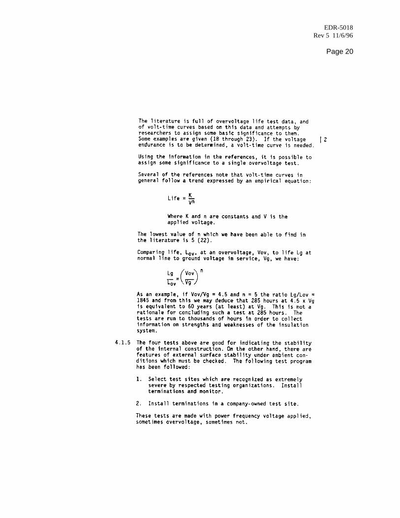
4.1.4The life at voltages far above normal line to ground must be adequate. Not onlymust the life be adequate to assure no failures on the one minute and six hourtests of reference (8), it must be adequate to assure that no failures will occur in40 years of normal voltage application.
Actually, items 1, 2, and 3 of this section already provide a good part of thisassurance. They assure that during normal operation, no discharges will occur.Without discharges the life should be infinite. An overvoltage life test is primarilya test for searching for any possible weaknesses which may not have appearedin tests of items 1, 2, and 3.
EDR-5018Rev 5 11/6/96
Page 20

EDR-5018Rev 5 11/6/96
Page 21
There are two basic reasons for doing so much testing. First is the variability of climaticconditions in the field. No one test can possibly cover them all. The second reason issimply the recognition of the importance of stability of the outer surface relative to life.
In wet and polluted environments, leakage currents across the outer surface becomesufficient to cause localized drying which leads to dry banding. Localized arcing acrossthese bands will cause erosion and may result in surface tracking or localizeddegradation. Material tests of every batch of non-tracking material are made to assurethat the material properties are meeting company specifications. In addition, the designof the insulator, the shape of the sheds, the interface between the sheds and the tube ofnontracking material, the length of the termination, the number of sheds, all have effectson the response to the leakage currents.
4.2 Test Data Relative to Corona and Load Cycling of Terminations
4.2.1 General/Corona Extinction Voltage (CEV)
Two termination designs are used to eliminate the triangular void at the end of the cableinsulation shield. One uses a grease type void filler with extruded semicon cableshields, and the other uses conductive paint. Data will be presented with respect to bothdesigns.
4.2.2 Load Cycle Tests
4.2.2.1. Test Details
Three cable types were used:
a. 185mm2 (365kCM) 30KV, XLPE, graphite dispersion layer, conductiveshielding tape, copper tape, jacket.
b. 350kCM (177mm2) 15KV, XLPE (4.4mm) extrudedinsulation shield, copper tape, jacket.
c. 150mm2 (296kCM) 20KV, XLPE, graphite disper-sion layer, conductive shielding tape, coppertape, jacket.
For both a and b, three batches of SCTM representing the minimum, median andmaximum levels of specific impedance (see section 3.2.2.5) were tested. Theseimpedances were 0.7, 3, and 7 x 10⁸ ohm-cm. Using cable (a) two cable loops(four terminations) for each impedance level were
EDR-5018Rev 5 11/6/96
Page 22
placed on load cycle at 95oC conductor temperature 5 hours on/3 hours off for150 cycles at 2.6 Vg. Similarly on a separate test at 130oC, six cables wereplaced on test at 2.6 Vg for 150 cycles.
Using cable (b) two loops for each impedance level were placed on load cycle at95oC for 150 cycles, again at 2.6 Vg.
For cable (c) one SCTM representing the median level of impedance was tested.Three cable loops (6 terminations) were placed on load cycle at 95oC conductortemperature, 5 hours on/3 hours off for a total of 200 load cycles at 2.6 Vg.
Corona extinction voltage was measured initially and at the end of the test. Thiswas defined at the 3 picocoulomb level.
Discharge magnitude was measured at 2.9 Vg. After the load cycle a visualexamination was made to determine:
(a) Position and degree of discharge--if any.(b) Tightness of stress control and red nontracking tubings.
4.2.2.2. Test Results
The data for cable types a and b are shown in Table 6. The data for cable type c is inTable 7. The visual examination revealed no evidence of any instability.
4.2.4 Discussion
4.2.4.1. 150 load cycles at 130oC with 5 hours on/3 hours off is 1.5 times a full check ofthe 500 hour emergency warranty of the cable.
4.2.4.2 The load cycle test is a type of overvoltage life test and as such has somerelationship to projected life in service. If the voltage exponent is 5, the life indicated by150 load cycles is 16.2 years. This is greater than AEIC #5 requirements. Using thesame exponent, the AEIC #5 test is equivalent to 15.8 years with 14 of these years atemergency conditions. That is, 21 days at 2 Vg is equivalent to 21 x 25 or 1.84 years,
365

EDR-5018Rev 5 11/6/96
Page 23
and 21 days at 3 Vg is 21 x 35 or 15.8 years. Our test is not sequential. 365
We test to the equivalent of 16.2 years at 95oC and 130oC. The load cycle test is anextremely severe test and the implication of passing such a test is considered to besignificant with respect to a much longer life than 16 years. Using the same examinationtechnique, the 200 load cycle test of cable c at 2.5 Vg is equivalent to 18 years at Vg.
The usual criterion for passing a load cycle test is simply continued operation at the endof the test. However, Raychem would prefer to have a termination which meets initialcorona specifications at the end of this test. Many competitive termination products donot meet this criterion. As the following will show, we have met this goal.
Both initially and after 150 load cycles all 18 of cable types a and b terminations meetrequirements of references 1 and 8 with respect to CEV and discharge magnitudeversus voltage.

EDR-5018Rev 5 11/6/96
Page 24

EDR-5018Rev 5 11/6/96
Page 25
For cable type c, CEV's were measured at 5 picocoulombs. The data show that after200 load cycles the CEV's met specifications with a comfortable margin.
These data confirm the data with types a and b. It is not certain that the discharges inthose specimens which exhibited discharges were in the terminations. They may havebeen in the cable. The cables tested, however, were chosen for excellent stabilityduring load cycling.
4.3 Test Data Relative to Overvoltage Life
4.3.1 General
The following test program includes cables with extruded insulation shield and with thegraphite dispersion layer. The program will ultimately include 4 voltage levels for eachcable. To conserve testing equipment the test was started at the highest voltage.
4.3.2 Details of the Test
Power frequency - 50Hz
Cable types (termination type)
15kV, 350kCM, XLPE (175 mils)
(extruded insulation shield)
20kV, 185mm2, XLPE
(graphite dispersion layer insulation shield)
Termination - standard indoor
No. of samples - 3 at each test voltage
4.3.3 Test Results
4.3.3.1. The test data are shown in Table 8.

EDR-5018Rev 5 11/6/96
Page 26

EDR-5018Rev 5 11/6/96
Page 27
4.3.4.4. The most significant fact that this test reveals is that the 0.5 picocoulombdischarges measured at about 2.4 Vg on these terminations are not having a significanteffect on useful life. That is, they may be determining the life but their effect is so smallthat even at 62kV (5.3 Vg) the life is greater than 11,000 hours. This correlates with thefact that discharge magnitude increases very slowly with voltage.
4.4 Data Regarding Life in Polluted Test Sites/Surface Stability
Several test sites have been chosen to assess the performance of Raychemterminations. Table 9 gives the relevant data. The predicted service life has beenderived from the classical life equation using a voltage exponent n of 5. It may be addedthat all 17 terminations at the Raychem test site shown in Table 9 were recentlyremoved for testing. All CEV's were over 22kV.
4.4.2 The data in Table 9 must be supplemented with field data on tens of thousands ofterminations installed outdoors in all parts of the world for an estimated averageinstalled life of 5 years. (Maximum installed life in use conditions 10 years.)
Accelerated artificial pollution tests for use with cable accessories have been proposedin a recent publication (25) which is a step toward a guide and possibly a standard.World wide progress is reviewed and a status report is included. It is concluded thatinterlaboratory work involving the tests themselves and comparisons with outdoorservice is needed before a formal guide can be written.

EDR-5018Rev 5 11/6/96
Page 28

EDR-5018Rev 5 11/6/96
Page 29
REFERENCES
(1) AEIC #5, "Specifications for Polyethylene and Crosslinked Polyethylene Insulated ShieldedPower Cables Rate 5 Through 69kV"
(2) IEEE #1, "General Principles Upon Which Temperature Limits are Based in the Rating ofElectric Equipment"
(3) IEEE #98, "Guide for Procedures for Thermal Indexes of Solid Electrical InsulatingMaterials"
(4) IEEE #99, "Guide for the Preparation of Test Procedures for the Thermal Evaluation ofInsulation Systems for Electrical Equipment"
(5) IEEE #101, "Guide for the Statistical Analysis of Thermal Life Test Data"
(6) IPCEA Pub. No. 5-66-524, "Cross-linked-thermosetting Polyethylene -insulated Wire andCable for the Transmission and Distribution of Electrical Energy"
(7) IPCEA, P-32-382, "Short Circuit Characteristics of Insulated Cable"
(8) IEEE #48, "Standard for High Voltage Alternating Current Cable Terminations"
(9) Raychem Report #110
(10) IEC Publication #505, "Guide for the Evaluation and Identification ofInsulation Systems of Electrical Equipment"
(11) ISO 2578
(12) Blake, A. E., Clarke, G. J., and Starr, W. T., "Improvements inStress Control Materials," Proc. 1979 Transmission and DistributionConference, 79 CH 1399-5-PWR, pgs. 264-270
(13) Marks Standard Mechanical Engineering Handbooks, pgs. 4-70, Table 11
(14) Raychem Report #79, Penneck, R. J., February 18, 1977
(15) Clabburn, R. J. T., Penneck, R. J., and Swinmurn, C. J., "Some Parameters Affecting theOutdoor Performance of Plastic Materials Used in Cable Accessories," Trans. IEEE, PAS 921833-42 (1973).
(16) Nyberg, D. D. and Penneck, R. J., "Improvements in Non-TrackingMaterials," 1979 IEEE Underground Transmission and DistributionConference, CH 1139-5-79-0000-341, pgs. 341-346

EDR-5018Rev 5 11/6/96
Page 30
(17) Penneck, R. J., Clabburn, R. J. T., and Swinmurn, C. J., "Laboratory Methods Useful inPredicting Outdoor Service Life of High Voltage Insulation Materials"
(18) Occhini, E., "A Statistical Approach to the Discussion of Dielectric Strength in ElectricCables" IEEE paper 72 TP 157 PWR
(19) Metra, P., Occhini, E., and Portinari, G., "High Voltage Cables With Extruded Insulation -Statistical Controls and Reliability Evaluation," Trans. IEEE, PAS 94 (3) pp. 967-75 May-June1975
(20) Kreuger, F. H., and Bentvelsen, P.A.C., "Breakdown Phenomena in P.E. Insulated Cable,"CIGRE Paper 21-05 1972
(21) Simoni, L., and Pattini, G., "A New Research into the Voltage Endurance of SolidDielectrics," Trans. IEEE, EI, 10 pp. 17-27 March 1975
(22) Lawson, J. H., and Vahlstrom, W., Jr., "Investigation of Insulation Deterioration in 15kV and22kV Polyethylene Cables Removed from Service Part II," Trans. IEEE, PAS 92 824-35 (SeeDiscussion by G. H. Hunt)
(23) Starr, W. T., and Endicott, H. S., "Progressive Stress-A New Accelerated Approach toVoltage Endurance," Trans. IEEE-PAS 80 Aug. 1961, pp. 515-22
(24) IEEE #4 Standard Techniques for High Voltage Testing. This describes short time artificialpollution tests. Extended time tests are run under similar ambients.
(25) Report of Working Group 12-39 on Weathering of the Insulated Conductor Committee ofthe IEEE (Principal Author - W. T. Starr) "Proposed Extended Time Artificial Pollution Tests forPolymeric Cable Accessories." Paper No. 845M 503-9 Presented at Summer PowerMeeting 1984. (To appear in PAS after 1/85).

EDR-5018Rev 5 11/6/96
Page 31

EDR-5018Rev 5 11/6/96
Page 32

EDR-5018Rev 5 11/6/96
Page 33
Since the apparent activation energy of the HVTM is about 27.7 k Cal, the rated lifetemperature corresponding to 90oC rated temperature is about 80oC.
This statement cannot be made about the SCTM. It is not in contact with the conductor and isapproximately 10oC cooler than the conductor with a temperature excursion of about 35oC. Itsapparent activation energy is 31.5 k Cal. Combining these assumptions in the same type ofanalysis yields a rated life temperature of 69oC.
These values of Rated Life Temperature are not used in this report. They help to provideperspective with respect to life data. Remember, these values represent an estimate of a worstcase situation.

EDR-5018Rev 5 11/6/96
Page 34

EDR-5018Rev 5 11/6/96
Page 35