edl message interface specification v4.0 - national grid · national grid company neta project edl...
TRANSCRIPT

NATIONAL GRID COMPANY
Control Technology
NETA Project
Copyright © 2000 The National Grid Company plc. All rights reserved. Nopart of this document may be reproduced, stored in a retrieval system ortransmitted in any form or by any means, whether electronic, photocopying,recording or otherwise, without the prior permission of the issuing authority:NGC Control Technology, St Catherine’s Lodge, Bearwood Road,Sindlesham, Berkshire, RG41 5BN, UK. Tel +44 118 936-3116, Fax 936-3118.
NETA Project EDL Message InterfaceSpecification
CT/24.13.0013
Issue 4, 20-June-2000
Neil Ashley


National Grid Company NETA Project EDL Message Interface SpecificationControl Technology
CT/24.13.0013 i 20-June-2000, Issue 4
CONTENTS
1 INTRODUCTION ................................................................................................... 1Figure 1.Process Layers in EDL System............................................................................................................... 2Figure 2.Diagram of EDL Processes ..................................................................................................................... 3
1.1 Purpose and Scope ................................................................................................................................... 41.2 Definitions.................................................................................................................................................. 41.3 Related Documents................................................................................................................................... 4
2 Message Structure Details........................................................................................ 52.1 Message Guidelines - General Description .......................................................................................... 52.2 Message Prefix Part .................................................................................................................................. 6
Table 1.Message Prefix Part for MMS Input Mailbox....................................................................... 6Table 2.Message Prefix Part for MMS Output Mailbox.................................................................... 6Table 3.Message Prefix Part for CMS Output Mailbox..................................................................... 7
2.3 Message Header Part ................................................................................................................................ 7Table 4.Message Header Part ................................................................................................................. 7Table 5.Message Header Categories ..................................................................................................... 8Table 6.Message Header Types ............................................................................................................. 8Table 7.Message Header Instruction Types ........................................................................................ 8Table 8.Message Header Error Flags.................................................................................................... 9
2.4 Message Data Part .................................................................................................................................... 92.4.1 Control Messages ........................................................................................................................... 9Table 9.Message Data Part for Control Messages ............................................................................ 10Table 10. Control Error Messages ....................................................................................................... 11Table 11. Message Data Part for Version Messages ........................................................................ 112.4.2 Instruction Messages ................................................................................................................... 12Table 12. Message Data Part for Status Change Instruction Messages ........................................ 12Table 13. Message Data Part for BOA and Deemed Closed Instruction Messages .................... 13Table 14. Message Data Part for Change of Reason Code Instruction Messages....................... 14Table 15. Message Data Part for Voltage / MVAR Instruction Messages ................................... 15Table 16. Message Data Part for Pumped Storage Unit Instruction Messages ............................ 16Table 17. Instruction Message Error Codes ....................................................................................... 182.4.3 Submission Messages .................................................................................................................. 19Table 18. Message Data Part for Submission Messages .................................................................. 19Table 19. Message Data Part Variations for MEL/MIL Submission Messages .......................... 20Table 20. Message Data Part variations for RUR/RDR Export/Import Submissions ................ 20Table 21. Message Data Part variations for Single Time Value Parameter Submissions.......... 21Table 22. Message Data Part Variations for SEL/SIL Submission Messages ............................. 21Table 23. Message Data Part for variations for Maximum Delivery Submission Messages .... 212.4.4 Submission Error codes .............................................................................................................. 21Table 24.Submission Error Codes ....................................................................................................... 22
2.5 Undelivered Messages ........................................................................................................................... 232.6 Alarm Messages ...................................................................................................................................... 23
Table 25. Alarm codes for CMS Alarm Mailbox.............................................................................. 23Table 26. CMS Alarm Codes ............................................................................................................... 23Table 27. Alarm codes for the MMS Alarm Mailbox....................................................................... 24Table 28. MMS Alarm Codes............................................................................................................... 24
DOCUMENT STATUS........................................................................................................................................ 25

National Grid Company NETA Project EDL Message Interface SpecificationControl Technology
CT/24.13.0013 ii 20-June-2000, Issue 4

National Grid Company NETA Project EDL Message Interface SpecificationControl Technology
CT/24.13.0013 1 20-June-2000, Issue 4
1 INTRODUCTIONElectronic Dispatch Logging is the existing principal mechanism by whichpower stations in the existing Pool receive instructions from NGC andredeclare availability and dynamic parameters to NGC.
Under NETA within the rolling Balancing Mechanism window, thebalancing of the power system is NGC’s sole responsibility. A secure,reliable and proven system for issue and acceptance of balancing instructionsis a pre-requisite for NGC prior to first operation of the power system underNETA. The EDL approach has been adopted for NETA as it is familiar tomany and therefore represents a low risk to the NETA programme againstthe target implementation date.
EDL is the means by which a Control Point for a single or number of BMUscommunicates with NGC. Any Control Point who wishes to receivebalancing market instructions and Ancillary Services instructions from NGCunder NETA must have an EDL link to NGC. An overview of the interfaceswith NGC under NETA was given in a DISG paper 19/01.
Logically the EDL system comprises four layers; Application,Communication, Server and Wide-area Network as illustrated in Figure 1.
• Application Layer. This contains the Man-Machine User Interface andother supporting processes. This layer is provided entirely by each ofNGC and the Company responsible for the Control Point to meet theirown individual requirements.
• Communication Layer1. This provides the interface between theapplication layer (often via a database) and the server layer (viamessages). It is primarily the Communications Layer which implementsthe interface described in this document. This layer is provided by eachof NGC and the Company responsible for the Control Point to meet boththeir own individual requirements and the functional requirements of theEDL Server Layer.
• Server Layer. This is that part of the Wide-area Network Layer whichtransfers data between origins and destinations within a network-serverdomain (transparent task to task communication) to provide the messagedelivery system. This layer is provided by NGC.
• Wide-area Network layer. For present purposes, this may be taken toinclude the lower layers (i.e. physical and data link layers) of the requiredcommunications stack. It may be TCP/IP (NGC’s preferred option)provided by any platform vendor or DECnet provided by Compaq.
Note that NGC can supply software to a company that is responsible for the ControlPoint that fulfils the requirements of the four layers. This software runs under theWindows NT4 operating system and connects to NGC using TCP/IP.
1 Not to be confused with the seven Communications Layers of the ISO OSI Model

National Grid Company NETA Project EDL Message Interface SpecificationControl Technology
CT/24.13.0013 2 20-June-2000, Issue 4
Figure 1. Process Layers in EDL System
The logical implementation of the layer strategy is illustrated in Figure 2.The interface between the Communications Layer and the Server Layer is viamessages deposited in four inter-process communications queues. It is theformat of these messages that is the subject of this document.
Application Layer
Communications Layer
Server Layer
Wide-areaNetwork Layer
Application Layer
Communications Layer
Server Layer
National Grid Control Centre Control Point

National Grid Company NETA Project EDL Message Interface SpecificationControl Technology
CT/24.13.0013 3 20-June-2000, Issue 4
Figure 2. Diagram of EDL Processes
The Server Layer consists of a single process on each node. The MasterMessage Server (MMS) runs on the NGC node and establishes connectionsto a Client Message Server (CMS) on each Control Point node.
DisplaySystem
CPUI
EDLmanager
CPInterface
CMSMMS
Database Database
Alarm Q
Undeliv'd Q
Output Q
Input Q
Configuration
Alarm Q
Undeliv'd Q
Output Q
Input Q
National Grid Control Centre Control Point CP
Application Layer
Communication Layer
Server Layer

National Grid Company NETA Project EDL Message Interface SpecificationControl Technology
CT/24.13.0013 4 20-June-2000, Issue 4
1.1 Purpose and ScopeThis document defines the structure and content of EDL instruction andsubmission messages that are required to implement Phase 1 of the NETAproject.
1.2 DefinitionsBMU Balancing Mechanism UnitBOA Bid Offer AcceptanceEDL Electronic Dispatch Logging – A message transfer mechanismMEL Maximum Export LimitMIL Maximum Import LimitMNZT Minimum Non-Zero TimeMZT Minimum Zero TimeNDZ Notice to Deviate from ZeroNETA New Electricity Trading ArrangementsNTB Notice to Deliver BidsNTO Notice to Deliver OffersRDR Run-down RatesRUR Run-up RatesSEL Stable Export LimitSIL Stable Import Limit
1.3 Related Documents1. NETA – A Draft Specification for the Balancing Mechanism and Imbalance
Settlement, Version 1.2, July 1999, The Office of Gas and Electricity Markets.2. NETA – Data Validation, Consistency and Defaulting Rules, CT/24.12.0003.

National Grid Company NETA Project EDL Message Interface SpecificationControl Technology
CT/24.13.0013 5 20-June-2000, Issue 4
2 MESSAGE STRUCTURE DETAILS
2.1 Message Guidelines - General DescriptionAll messages are simple ASCII text strings to aid development ofApplication and Communication layers by all parties. With the exception ofServer Messages the messages comprise three parts.
• A message Prefix Part
• A message Header Part
• A message Data Part
The message Prefix Part is not transmitted between computer systems. It isused for communication between the Communications Layers and the ServerLayers of the system on each node.
Message Prefix Parts are removed by the Server Layer from messagesreceived from the Communication Layer before sending the messages to theWide-area Network Layer for transmission.
Messages Prefix Parts are added by the Server Layer to messages receivedfrom the Wide-area Network Layer before sending the messages to theCommunication Layer.
The message Header Part is constructed by the Communication Layers.
The message Data Part is constructed by the Communication Layer, usuallybased on information from the Application Layer, although some messagesare originated by the Communications Layer.
This separation between Header & Data Parts is notional. In practice someelements of the Data Part will be processed by the Communications Layers.Furthermore the boundary between Header and Data Parts has beendeliberately constructed such that the common components of all messagesare arranged at the beginning of the Data Part and so may be viewed as eitherHeader or Data Parts.
All dates and times2 are referenced to Greenwich Mean Time.
Times stamps within message Data Parts are to a resolution of one minute.The standard DEC-VMS format is used. i.e. dd-mmm-yyyy hh:mm. (17characters). Note that the valid range of the time component is 00:00 to23:59.
Time stamps within message prefix parts are to a resolution of 10ms. Thestandard DEC-VMS format is used. i.e. dd-mmm-yyyy hh:mm:ss.nn. (23characters). Note that the valid range of the time component is 00:00:00.00to 23:59:59.99.
2 Inter-machine time comparisons should only be to a minute resolution

National Grid Company NETA Project EDL Message Interface SpecificationControl Technology
CT/24.13.0013 6 20-June-2000, Issue 4
Fields within the Prefix Parts and the Data Parts are delimited by a spacecharacter. All message parts are terminated with a ^ character.
Fields containing variable length text items are left justified and space filled.
Fields containing variable length numeric items are right justified and zerofilled.
The leading character of the day part of a date/time field may be a space.
Messages consist of three types; control, instruction and submission.Select/deselect control messages are sent from NGC to a Control Point whilepath/nopath control messages are sent from a Control Point to NGC. Thesemessages control the availability of a BM Unit both to be instructed by NGCand to submit dynamic parameters. For instruction and submission messagesto be exchanged, NGC must first have sent a select message while theControl Point must have sent a path message. Various message formats aredefined for Ancillary Service instructions and Balancing Market Bid/OfferAcceptance instructions that are used by NGC to instruct a Control Point.Likewise, submission message formats are defined which allow a ControlPoint to submit various BM Unit dynamic parameters to NGC. If an error isdetected by the Control Point in an instruction message, or by NGC in asubmission message, the text of the message, or the truncated part thereofcontaining a reference number and log time will be sent back to theoriginator together with a pre-defined error code.
2.2 Message Prefix PartThe message Prefix Part is different for each mailbox between theCommunication Layer and the Server Layer. There is no Prefix Part onmessages from the Communication Layer to the Server Layer on the stationnode , i.e. on messages in the CMS input mailbox.
Table 1. Message Prefix Part for MMS Input Mailbox
Field Name StartPosition
FieldSize
Description
Destination 1 6 Name of Control PointTerminator 7 1 Part terminator character "^"
Table 2. Message Prefix Part for MMS Output Mailbox
Field Name StartPosition
FieldSize
Description
Destination 1 6 Name of Control PointTime-Stamp 8 23 Time message received from Wide-area
Network. Obtained from local node systemclock.
Terminator 31 1 Part terminator character "^"

National Grid Company NETA Project EDL Message Interface SpecificationControl Technology
CT/24.13.0013 7 20-June-2000, Issue 4
Table 3. Message Prefix Part for CMS Output Mailbox
Field Name StartPosition
FieldSize
Description
Time-Stamp 1 23 Time message received from Wide-areaNetwork. Obtained from local node systemclock.
Terminator 24 1 Part terminator character "^"
2.3 Message Header PartThe message Header Part is a packed string of four characters followed by aterminator. The character positions and sizes of the various fields aredescribed in Table 4.
Table 4. Message Header Part
Field Name StartPosition
FieldSize
Description
Category 1 1 The category of message. Instruction,Submission etc. See Table 5
Type 2 1 The type of the message. This field carriesthe dialogue between Communication Layers.See Table 6 for details.
InstructionType
3 1 NOTE: This field is only used for InstructionCategory Messages and is a space for allother Categories of messageSee Table 7 for Details.
Error 4 1 Flag set to space by originating process. Themessage may be returned with the flag set.See Table 8 for details.
Terminator 5 1 Part terminator character "^"
Each transaction dialogue between Communication Layers consists of asingle new outgoing message followed by one or more returned messages.Return messages are referenced to the original message and have returnmessage types as shown in Table 6 They also retain the Message Categoryand Instruction Type of the original message.

National Grid Company NETA Project EDL Message Interface SpecificationControl Technology
CT/24.13.0013 8 20-June-2000, Issue 4
Table 5. Message Header Categories
Category Description
C Control Messages. See Table 9 for Data Part details
I Instruction Messages. See Table 12, Table 13, Table 14, Table 15 andTable 16 for Data Part details
R Submission Messages. See Table 18 for Data Part Details
Table 6. Message Header Types
Code Mnemonic Direction MeaningN New Send A new (real-time) message.W Waiting Return The remote Communications Layer has
received & validated the referencedmessage. It is now waiting for manualaction. This type is often called TechnicalAcknowledgement in earlier papers.
U UserAcknowledgements
Return The remote operator has seen the referencedmessage.
A Acceptance Return The remote operator accepts the referencedmessage.
R Reject Return The remote operator rejects the referencedmessage.
T Telephoned Send Upon re-connection of systems, messagesthat have been transmitted by telephone aresent electronically to allow the systems toreconcile themselves.
D Dispute Return The remote system cannot reconcile amanually entered transaction.
Table 7. Message Header Instruction Types
InstructionType Code
Meaning
Space Control Message, Submission Message, or EDL closed instructionmessages.See Table 9, Table 12, Table 13, Table 14 and Table 18 for Data Partdetails
V EDL Voltage Control Instruction.
See Table 15 for Data Part details.
P Pumped Storage Message. See Table 16 for details

National Grid Company NETA Project EDL Message Interface SpecificationControl Technology
CT/24.13.0013 9 20-June-2000, Issue 4
Table 8. Message Header Error Flags
Error Flag Meaning
Space Original message
E An error is detected in a received message. Either the original messageis returned to the originator with a four-character error code appended toit or a new message identifying the reference number of the originalmessage together with a 4-character error code is sent to the originator.The error code may relate to the syntax or data consistency of themessage
X A message is returned to the originator. The message was valid and dataconsistent when first received, but while waiting for a useracknowledgement, other parameters have changed and the message is nolonger consistent. It is thus flagged as eXpired i.e. a valid message that isno longer meaningful.
2.4 Message Data PartThe content of the Message Data Part depends primarily on the MessageCategory and secondarily on the Message Type. In the case of InstructionCategory Messages the Instruction Type also influences the Message DataPart. Single space characters to further enhance the readability of themessages separate fields within the Message Data Parts. The Message DataParts for each category are defined in the following tables.
2.4.1 Control Messages
The Message Data Part for control messages is a maximum of 56 characters.The length and contents of control messages depends on the nature of themessage, the options are detailed in Table 9.

National Grid Company NETA Project EDL Message Interface SpecificationControl Technology
CT/24.13.0013 10 20-June-2000, Issue 4
Table 9. Message Data Part for Control Messages
FieldName
StartPosition
FieldSize
Description ValidType
ErrorFlag
Name 1 9 Control Point Name (VERSONmessage only) or BM Unit Name
All
RefNumber
11 10 Message Reference Number All
Log Time 22 17 Time message logged byoriginating process
All
Type 40 6 Specifies the type of controlmessage and the structure of thetype dependent message part.
N
Type Details
VERSON See Table 11
SELECT The Control Point isselected by NGC forEDL.
DESEL The Control Point isde-selected by NGCfor EDL
PATH There is a path fromthe Control PointCommunicationLayer to the BMUnit operator.
Typedependant
NOPATH There is NO pathfrom the stationCommunicationLayer to the BMUnit operator
Error Code 40, 47 or52
4 See Table 10 for meaning Any E
Terminator 44, 39,46, 51, or56
1 Part terminator character "^" All
Dispatch Instructions to an individual BM Unit via EDL will only take placeonce a PATH message from the control point, and a SELECT message fromNGC have been sent. All other states will result in Instructions being issuedby voice telephone.

National Grid Company NETA Project EDL Message Interface SpecificationControl Technology
CT/24.13.0013 11 20-June-2000, Issue 4
Table 10. Control Error Messages
Error Code Description
C001 Invalid Control Point/BM Unit ID
C002 Invalid Control Type
C003 Unsupported Version Number
C004 Message arrived before VERSON accept
Submission and Control Messages can be issued at any time, irrespective ofselect and path states.
Table 11. Message Data Part for Version Messages
Field Name StartPosition
Field Size Description
Type 40 6 VERSON
Version 47 4 Latest Supported EDL Interface Definition.The field is a formatted numeric value. e.g.0021 to specify version 2.1. The versionnumber is changeable and reflects the currentlevel of messages supported at NGC and theControl Point.

National Grid Company NETA Project EDL Message Interface SpecificationControl Technology
CT/24.13.0013 12 20-June-2000, Issue 4
2.4.2 Instruction Messages
2.4.2.1 Status Change Instruction MessagesThe message Data Part for Status Change instruction messages is a maximumof 104 characters.
Note that Status Change instructions are to be issued for Ancillary Servicepurposes to change the operating state of a BM Unit, for example perhaps toinstruct a Unit to synch to the declared FPN, or to instruct a Unit off. If aMW output level is to be instructed, a Bid/Offer Acceptance closedinstruction must be issued.
Table 12. Message Data Part for Status Change Instruction Messages
FieldName
StartPosition
FieldSize
Description ValidType
ErrorFlag
Name 1 9 BM Unit Name AllRefNumber
11 10 Instruction Reference Number All
Log Time 22 17 Time message logged byoriginating process
All
StartInstructionCode
40 5 This may be one of the followingcodes SYN, HTS or the numericvalue 0.
N, T
StartReserve
46 3 Not used. N, T
Start Time 50 17 Start time of the instruction. N, TReasonCode
68 3 Three character reason code appliedto steam plant; the first characterexplains why the instruction wasissued, the second characterindicates whether the BM Unit is infrequency response mode.
N,T
TargetInstructionCode
72 5 This may be one of the followingcodes OFF, HTS, CHS or thenumeric value 0.
N, T
TargetReserve
78 3 Not used. N, T
TargetTime
82 17 Target time of the instruction. N, T
Error Code 40, 100 4 See Table 17 for meaning Any E, XTerminator 39, 44,
99 or 1041 Part terminator character "^" All
Participants and Vendors should contact NGC for an up-to-date list of reasoncodes and an accompanying explanation.

National Grid Company NETA Project EDL Message Interface SpecificationControl Technology
CT/24.13.0013 13 20-June-2000, Issue 4
2.4.2.2 Bid / Offer Acceptance and Deemed Closed Instruction MessageThe message Data Part for a closed instruction is a maximum of 183characters in length. A closed instruction will be sent to accept either BMUnit Bids or BM Unit Offers. The closed instruction must contain at leasttwo MW / time value pairs up to a maximum of five value pairs that describea closed volume of energy (in conjunction with the physical notification andany relevant previously accepted BOAs).
Table 13. Message Data Part for BOA and Deemed Closed InstructionMessages
FieldName
StartPosition
FieldSize
Description ValidType
ErrorFlag
Name 1 9 BM Unit Name AllRefNumber
11 10 Instruction Reference Number All
Log Time 22 17 Time message logged byoriginating process
All
Type 40 4 Type of instruction. BOAI orDEEM.
N, T
BOANumber
45 10 BM Unit Bid/Offer AcceptanceNumber
N, T
Number ofDataPoints
56 2 Count of the number of MW / Timepairs that make up this closedinstruction. There must be aminimum of 2 pairs and amaximum of 5.
N, T
MW1 59 5 MW Value 1
T1 65 17 Time value 1
±nnnn N,T
MW2 83 5 MW Value 2
T2 89 17 Time value 2Error code A
N, T
MW3 107 5 MW Value 3
T3 113 17 Time value 3
Optional MW /Time pair 3;Error code B
N, T
MW4 131 5 MW Value 4
T4 137 17 Time value 4
Optional MW /Time pair 4;Error code C
N, T
MW5 155 5 MW Value 5
T5 161 17 Time value 5
Optional MW /Time pair 5;Error code D
N, T
Error Code 40,107 A,131 B,155 C,
179 D
4 See Table 17 for meaning Any E, X
Terminator 39, 44,106, 111,130, 135,154, 159
178, 183
1 Part terminator character "^" All

National Grid Company NETA Project EDL Message Interface SpecificationControl Technology
CT/24.13.0013 14 20-June-2000, Issue 4
2.4.2.3 Reason Code Instruction MessagesThe message Data Part for a reason code instruction message is a maximumof 71 characters. This instruction sets the current reason code for a BM Unit.It is used, for example, to instruct a BM Unit’s frequency response.
Table 14. Message Data Part for Change of Reason Code InstructionMessages
FieldName
StartPosition
FieldSize
Description ValidType
ErrorFlag
Name 1 9 BM Unit Name AllRefNumber
11 10 Instruction Reference Number All
Log Time 22 17 Time message logged byoriginating process
All
Type 40 4 Type of instruction. REAS N, TReasonCode
45 3 Three character reason code. N, T
Start Time 49 17 Start time of the instruction. N, TError Code 40, 67 4 See Table 17 for meaning Any E, XTerminator 39, 44,
66 or 711 Part terminator character "^" All
Participants and Vendors should contact NGC for an up-to-date list of reasoncodes and an accompanying explanation.

National Grid Company NETA Project EDL Message Interface SpecificationControl Technology
CT/24.13.0013 15 20-June-2000, Issue 4
2.4.2.4 Voltage / MVAR Instruction MessagesThe message Data Part for Voltage Instruction messages is a maximum of 73characters. All voltage control instructions are supported by EDL level 2(VERSON 0020).
Table 15. Message Data Part for Voltage / MVAR Instruction Messages
FieldName
StartPosition
FieldSize
Description ValidType
ErrorFlag
Name 1 9 BM Unit Name AllRefNumber
11 10 Instruction Reference Number All
Log Time 22 17 Time message logged byoriginating process
All
Type 40 4 Type of instruction. MVAR orVOLT
N, T
Value 45 4 Target value as a whole numberpreceded by minus ("-" = negativevalue), plus ("+" = positive value),or space (" " = positive value) andwith 3 digits (i.e. leading zero'salways supplied). Note: + zero & - zero are treatedas same instruction
N, T
TargetTime
50 17 Target time of the MVAR or VOLTinstruction.
N, T
Error Code 40, 68 4 See Table 17 for meaning Any E, XTerminator 39, 44,
67 or 721 Part terminator character "^" All

National Grid Company NETA Project EDL Message Interface SpecificationControl Technology
CT/24.13.0013 16 20-June-2000, Issue 4
2.4.2.5 Pumped Storage Instruction MessagesFor Pumped Storage plant, currently Dinorwig and Ffestiniog stations, MWloading and pump instructions will use the closed instruction format given inTable 13.
The following message format will be used to set a pumped storage unit’s:
• current reason code
• droop value
• low frequency relay value
• current operating state
Voltage instruction messages will be in the standard format as described inTable 15.
Table 16. Message Data Part for Pumped Storage Unit Instruction Messages
FieldName
StartPosition
FieldSize
Description ValidType
ErrorFlag
Name 1 9 Pumped Storage Unit Name AllRefNumber
11 10 Instruction Reference Number All
Log Time 22 17 Time message logged byoriginating process
All
ReasonCode
40 4 Four character reason code, (seebelow for more detail)
N, T
Start Time 45 17 Start time of instruction. N, T
Target 63 5 Depending on the reason code: amnemonic or a real value (seebelow for more detail).
N, T
TargetTime
69 17 Target time of the instruction. N, T
Error Code 87 4 See Table 17 for meaning Any E, XTerminator 92 1 Part terminator character "^" All
Reason Codes can be one of the following
ReasonCode
Description
LFSM Limited Frequency Sensitive Mode
PSHF Carry Primary, Secondary and High Frequency Response
EMRG Emergency instruction (instruction to operate outside declared parameters)
FRES Fast Response Required
LFRY Instruction to set an Low Frequency relay
DROP Droop instruction
BKDN Breakdown

National Grid Company NETA Project EDL Message Interface SpecificationControl Technology
CT/24.13.0013 17 20-June-2000, Issue 4
Target Field can be one of the following
Target Description
MW Reason code to be applied to the Pumped Storage BOA Closed Instruction
SH Shutdown
SG Spin Gen
SP Spin Pump
nn.nn Set low frequency relay to nn.nn Hz. For example nn.nn could be 49.85.Where nn.nn is sent as 00.00 this should be interpreted as >remove LF relaysetting=.
n.n Set droop to n.n %
Truth table
MWpositiveoutput
SH SG SP MWnegativeoutput
nn.nn n.n
LFSM x x x x x
PSHF x x
EMRG x x x x x
FRES x
LFRY x
DROP x
BKDN x

National Grid Company NETA Project EDL Message Interface SpecificationControl Technology
CT/24.13.0013 18 20-June-2000, Issue 4
2.4.2.6 Instruction Message Error CodesThe error codes in Table 17 can be used with instruction messages.
Table 17. Instruction Message Error Codes
Error Code Description
I001 Invalid BM Unit ID
I002 Invalid Reference Number (Current reference < Last reference, or noprevious reference to instruction with this number)
I003 General instruction syntax error (instruction parsing failed)
I004 Instruction received for a BM Unit with NO PATH
I005 Instruction received before Version Control Procedure completed
I006 Telephoned Instruction received with an Invalid Reference Number.
I007 Attempt to recover previously rejected instruction
I008 Unable to log instruction
I009 Invalid Telegraph Instruction Number
I010 Attempt to Reject Reconciliation Instruction which has already been sentto Settlements

National Grid Company NETA Project EDL Message Interface SpecificationControl Technology
CT/24.13.0013 19 20-June-2000, Issue 4
2.4.3 Submission MessagesSubmission messages conform to the message structure and error checkingdetailed in Reference 2. The structure of the Data Part depends on theparameters being re-declared, the options are detailed in Table 18.
The message Data Part for Submission messages is a maximum of 107characters.
Table 18. Message Data Part for Submission Messages
FieldName
StartPosition
FieldSize
Description ValidType
ErrorFlag
Name 1 9 BM Unit Name AllRefNumber
11 10 Submission Reference Number All
Log Time 22 17 Time message logged byoriginating process
All
Type 40 6 Specifies the type of Submissionand the structure of the typedependent message part.
N, T
Type DetailsMEL, MIL(error code A)
Table 19
RURE, RURI,RDRE, RDRI(error code B)
Table 20
NDZ, NTO, NTB,MZT, MNZT(error code C)
Table 21
SEL, SIL(error code D)
Table 22
TypeDependent
47 Max 57
MDVP(error code E)
Table 23
N, T
Error Code 40 any,103 (A),79 (B),51 (C),57 (D),
61 (E)
4 Not used. Any E, X
Terminator 39, 44102, 107,78, 83,50, 55,56, 61,60, 65
1 Part terminator character "^" All
National Grid Company NETA Project EDL Message Interface SpecificationControl Technology
CT/24.13.0013 20 20-June-2000, Issue 4
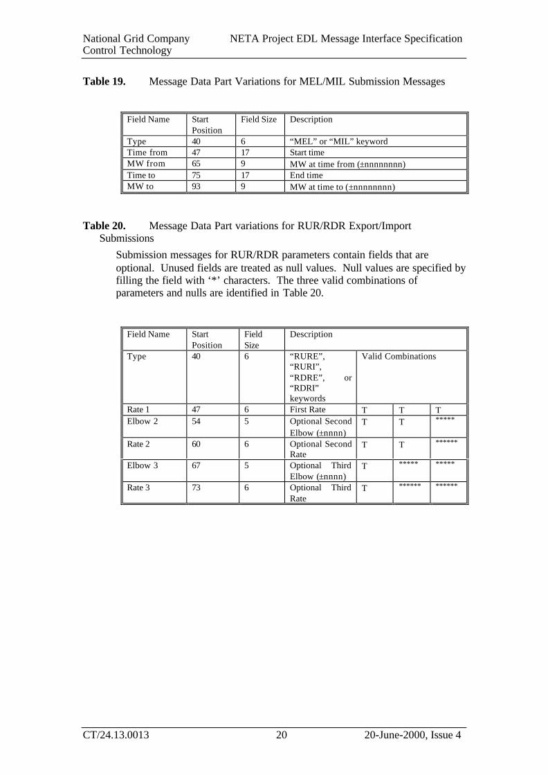
Table 19. Message Data Part Variations for MEL/MIL Submission Messages
Field Name StartPosition
Field Size Description
Type 40 6 “MEL” or “MIL” keywordTime from 47 17 Start timeMW from 65 9 MW at time from (±nnnnnnnn)Time to 75 17 End timeMW to 93 9 MW at time to (±nnnnnnnn)
Table 20. Message Data Part variations for RUR/RDR Export/ImportSubmissions
Submission messages for RUR/RDR parameters contain fields that areoptional. Unused fields are treated as null values. Null values are specified byfilling the field with ‘*’ characters. The three valid combinations ofparameters and nulls are identified in Table 20.
Field Name StartPosition
FieldSize
Description
Type 40 6 “RURE”,“RURI”,“RDRE”, or“RDRI”keywords
Valid Combinations
Rate 1 47 6 First Rate Τ Τ ΤElbow 2 54 5 Optional Second
Elbow (±nnnn)Τ Τ *****
Rate 2 60 6 Optional SecondRate
Τ Τ ******
Elbow 3 67 5 Optional ThirdElbow (±nnnn)
Τ ***** *****
Rate 3 73 6 Optional ThirdRate
Τ ****** ******

National Grid Company NETA Project EDL Message Interface SpecificationControl Technology
CT/24.13.0013 21 20-June-2000, Issue 4
Table 21. Message Data Part variations for Single Time Value ParameterSubmissions
Field Name StartPosition
FieldSize
Description
Type 40 6 “NDZ”, “NTO”, “NTB”, “MZT” or “MNZTkeyword
Time value 47 3 Number of minutes
Table 22. Message Data Part Variations for SEL/SIL Submission Messages
Field Name StartPosition
FieldSize
Description
Type 40 6 “SEL” or “SIL” keywordValue 47 9 MW level
Table 23. Message Data Part for variations for Maximum Delivery SubmissionMessages
Field Name StartPosition
FieldSize
Description
Type 40 6 “MDVP” keywordMDV 47 11 Max Delivery Volume (MW hours)MDP 59 3 Max. Delivery Period (minutes)
2.4.4 Submission Error codes
A submission message is automatically acknowledged by NGC using amessage with the message Header Part “RW ^”.
The submission undergoes syntax and validation checking. If the submissionis valid, the return message with the message Header Part “RU ^” is sent tothe Control Point; otherwise, if an error is encountered, a message with themessage header part “RN E” is sent with a reason code appended.

National Grid Company NETA Project EDL Message Interface SpecificationControl Technology
CT/24.13.0013 22 20-June-2000, Issue 4
Table 24. Submission Error Codes
Error Code Description
R001 Invalid syntax
R002 Invalid BM Unit
R003 Value out of bounds
R004 Invalid run rate break point
R005 Invalid run rate
R006 Invalid combination of run rates/breakpoints
R007 Invalid run rate breakpoint; breakpoints not monotonically increasing
R008 FROM time does not predate TO time
R009 Invalid FROM time
R010 Invalid TO time
R011 FROM time must be equal to or after SUBMISSION time
R999 Contact NGC

National Grid Company NETA Project EDL Message Interface SpecificationControl Technology
CT/24.13.0013 23 20-June-2000, Issue 4
2.5 Undelivered MessagesThere will be rare occasions when messages will not be acknowledged assuccessfully transferred from the Communications Layer on one node to theCommunications Layer on another node. This may be due to
• the message was not transferred – communications failure
• the remote message server failed to acknowledge receipt of thesuccessfully delivered message.
All such messages which cannot be delivered to the remote partner aredeposited in the undelivered mailbox on the sending node. Any messagePrefix Part in the input mailbox is also echoed to the undelivered mailbox.The Communications Layer must monitor this mailbox, and possibly re-present the message when connection is re-established.
2.6 Alarm MessagesThe Server Layer continuously monitors the Wide-area Network Layer.Whenever a connection with a remote partner changes, a message isdeposited in the Alarm mailbox.
Table 25. Alarm codes for CMS Alarm Mailbox
Field Name StartPosition
FieldSize
Description
Code 1 3 See Table 26Time Stamp 5 23 Time alarm raised by Server Layer, obtained
from local node system clock.
Table 26. CMS Alarm Codes
Alarm MeaningIC Input channel connectedOC Output channel connectedID Input channel disconnectedOD Output channel disconnectedNX Network Partner Exited

National Grid Company NETA Project EDL Message Interface SpecificationControl Technology
CT/24.13.0013 24 20-June-2000, Issue 4
Table 27. Alarm codes for the MMS Alarm Mailbox
Field Name StartPosition
FieldSize
Description
Destination 1 6 Name of BM UnitCode 8 6 See Table 28Time Stamp 15 23 Time alarm raised by Server Layer, obtained
from local node system clock.
Table 28. MMS Alarm Codes
Alarm MeaningC-P Primary Channel ConnectedC-S Secondary Channel ConnectedD-P Primary Channel DisconnectedD-P(R) Primary Channel disconnected due to a link re-configurationD-S(R) Secondary Channel disconnected due to a link re-
configurationD-P(U) Primary Channel disconnected due to a message being
undelivered/unacknowledgedD-S(U) Secondary Channel disconnected due to a message being
undelivered/unacknowledgedD-S Secondary Channel DisconnectedNX Network Partner Exited

National Grid Company NETA Project EDL Message Interface SpecificationControl Technology
CT/24.13.0013 25 20-June-2000, Issue 4
DOCUMENT STATUS
Product Description Reference: CT/24.22.0023
AMENDMENT RECORD
Issue Draft Date Auth Description of changes
4 20-Jun-2000 NA Add new NGC logo and quality watermark.
4 1 07-Jun-2000 NA Updated following comments arising from EDL type testing.
3 09-May-2000 NA Updated and issued after responding to comments on Issue 3, Draft1.
3 1 13-Apr-2000 RDG Updated to include Submission message reason codes
2 21-Jan-2000 NA Issued following review.
2 1 19-Jan-2000 NA Updated in response to comments received from OFGEM on Issue1. Also add Start Time field to the REAS instruction, and increasethe size of the elbow fields in the RUR/RDR messages from 4 to 5..
1 23-Dec-1999 NA Updated in response to comments from the NETA project team.
1 1 16 Dec 1999 NA Created from the document referred to in Reference 4.
CHANGE FORECAST
Once issued this document is not expected to change, however if it does it would be re-issued whole
DISTRIBUTION
This document will be stored in the NGC, System Management (SM) NETA electronic library.Requests from within NGC for copies should be made to the NGC, SM, NETA librarian.
A copy of the issued document will be given to the OFGEM NETA, Program Development Office fordistribution to parties external to NGC.
— End of Document —