edition logodrive programming interface 06/2001 · 3.2 editing the logodrive program ... 3 output...
TRANSCRIPT

LOGODrive Programming InterfaceEdition
06/2001
Manual1051631x / EN

SEW-EURODRIVE

LOGODrive Programming Interface – Manual 3
Contents1 Programming..................................................................................................... 4
1.1 General ..................................................................................................... 41.2 Prerequisites ............................................................................................. 4
2 LOGODrive Graphic Programming Interface.................................................. 52.1 Starting the LOGODrive graphic programming interface .......................... 52.2 General description of LOGODrive ........................................................... 6
3 First LOGODrive Program ................................................................................ 83.1 Establishing a new project ........................................................................ 83.2 Editing the LOGODrive program............................................................. 10
4 Compiling, Loading and Starting the LOGODrive Program........................ 164.1 Compiling the program............................................................................ 164.2 Upload..................................................................................................... 194.3 End LOGODrive...................................................................................... 19
5 Monitoring Functions...................................................................................... 205.1 Variable windows .................................................................................... 205.2 Display selected variables....................................................................... 21
6 Program Documentation ................................................................................ 236.1 Using comments ..................................................................................... 236.2 Printing a sample program...................................................................... 24
7 LOGODrive for Advanced Users.................................................................... 257.1 Changing the project characteristics ....................................................... 257.2 Deleting redundant variables .................................................................. 267.3 Program processing................................................................................ 267.4 Updating of inputs/outputs ...................................................................... 307.5 Processing times..................................................................................... 307.6 Processing times for the entire program ................................................. 307.7 Using TASK 2 ......................................................................................... 31
8 Examples ......................................................................................................... 328.1 Simple motor control ............................................................................... 328.2 Current detection .................................................................................... 33
9 Overview of Function Blocks ......................................................................... 359.1 Operands ................................................................................................ 359.2 Input terminals / output terminals ............................................................ 359.3 Arithmetic blocks..................................................................................... 359.4 Bit processing ......................................................................................... 369.5 Variable processing ................................................................................ 379.6 Comparison blocks.................................................................................. 379.7 Time blocks............................................................................................. 379.8 SEW functions ........................................................................................ 389.9 Other commands .................................................................................... 38
10 Index................................................................................................................. 39

4 LOGODrive Programming Interface – Manual
General
1 Programming
1.1 General
This section was designed to give you a relatively quick introduction to the LOGODrivegraphic programming interface. You will learn about the basic LOGODrive functions withthe help of an example that is gradually generated and expanded throughout the diffe-rent sections.
The introduction is divided into several steps that are dealing with the most importanttopics.
LOGODrive graphic programming interfaceIn this section, you will learn how to start and operate the LOGODrive graphic program-ming interface.
First LOGODrive programYou will generate your first LOGODrive program in this section.
Compiling and starting the LOGODrive programIn this section, you will compile the generated program, load it into the inverter andexecute it.
Monitoring functionsWe have created this step to control the program and visualize the values entered asvariables.
Documentation of the programA print function has been implemented in the LOGODrive graphic programming inter-face to print the formatted program.
LOGODrive for advanced usersThis section explains additional functions for operation of the LOGODrive.
1.2 Prerequisites
This introduction assumes that the user is familiar with the Windows95, Windows98,WindowsNT or Windows2000 operating systems as well as general operation ofWindows programs.
In addition, the MOVITOOLS program package version 2.6 or higher has to be installedin the "Programs/SEW...“ directory.
LOGODrive Programming Interface – Manual 5
Starting the LOGODrive graphic programming interface
2 LOGODrive Graphic Programming InterfaceIn this section, you will learn how to start the LOGODrive graphic programming interfaceand create a new project followed by an explanation regarding operation of the interface.
2.1 Starting the LOGODrive graphic programming interface
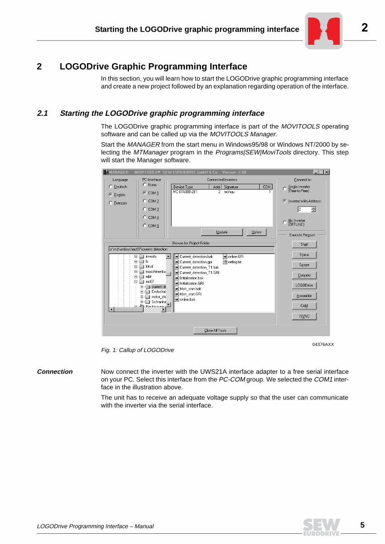
The LOGODrive graphic programming interface is part of the MOVITOOLS operatingsoftware and can be called up via the MOVITOOLS Manager.
Start the MANAGER from the start menu in Windows95/98 or Windows NT/2000 by se-lecting the MTManager program in the Programs|SEW|MoviTools directory. This stepwill start the Manager software.
Connection Now connect the inverter with the UWS21A interface adapter to a free serial interfaceon your PC. Select this interface from the PC-COM group. We selected the COM1 inter-face in the illustration above.
The unit has to receive an adequate voltage supply so that the user can communicatewith the inverter via the serial interface.
04376AXXFig. 1: Callup of LOGODrive

6 LOGODrive Programming Interface – Manual
General description of LOGODrive
The Update button finds all connected units and displays them in the unit list locatedabove. Your unit should now be displayed in the list. If you do not find the unit in this list,there is no connection between PC and inverter. Please check the connection.
The corresponding address will be set and the unit switched into ONLINE-Mode byselecting a unit from this list.
Now start the LOGODrive with the LOGODrive button.
2.2 General description of LOGODrive
The following program window will be visible after starting LOGODrive.
The program window is divided into five areas:
1. Menu bar All program functions are divided into groups in the menu bar. The File group containsall file operations, i.e. you can select the Open file, Close file, Save file, etc. functions inthis group.
04377AXXFig. 2: The LOGODrive window

LOGODrive Programming Interface – Manual 7
General description of LOGODrive
2. Symbol bar The execution statistics of task 1 and task 2 are initially shown in the symbol bar (fromleft to right), followed by interfaces with the following functions:
• Enter new form / project
• Open form
• Save form
• Save all forms
• Copy
• Cut
• Paste
• Start program
• Stop program
• Delete element
• Translate program
• Translate and load program
• Compare
3. Project window The files belonging to a project are displayed in the project window. The files are dividedinto the groups Initial Form(s), Task1 Form(s) and Task2 Form(s).
4. Main window The program files can be displayed in the main window. No file is displayed since noproject has been established yet.
5. Status bar The status bar contains information on the communications status (online, offline) andthe unit address.

8 LOGODrive Programming Interface – Manual
Establishing a new project
3 First LOGODrive ProgramYou will generate your first LOGODrive program in the course of this section.
3.1 Establishing a new project
You start a new project and display the following configuration window via the File / New/ Project... window.
You can determine the program components of the project in this window.
Entering data You will first enter the project name and path in which you want to save the project. Thisstep creates a subdirectory in the entered path with the project name.
You will then indicate which program groups are to be generated automatically. We willgenerate the groups for the Initial Form(s) and the Task 1 Form(s) in our example.
04378AXXFig. 3: Setting project characteristics
LOGODrive Programming Interface – Manual 9
Establishing a new project
The project characteristics also contain information on symbolic (global) and temporaryvariables.
The initialization group also contains the files with the program components required forinitializing the program or the inverter. These components are processed only once,immediately following the program start. The groups Task1 Form(s) and Task2 Form(s)contain those parts of the entire program that are processed cyclically. Task1 and Task2set themselves apart by different processing times (see "LOGODrive for AdvancedUsers").
We will now create an initialization file and a program file.
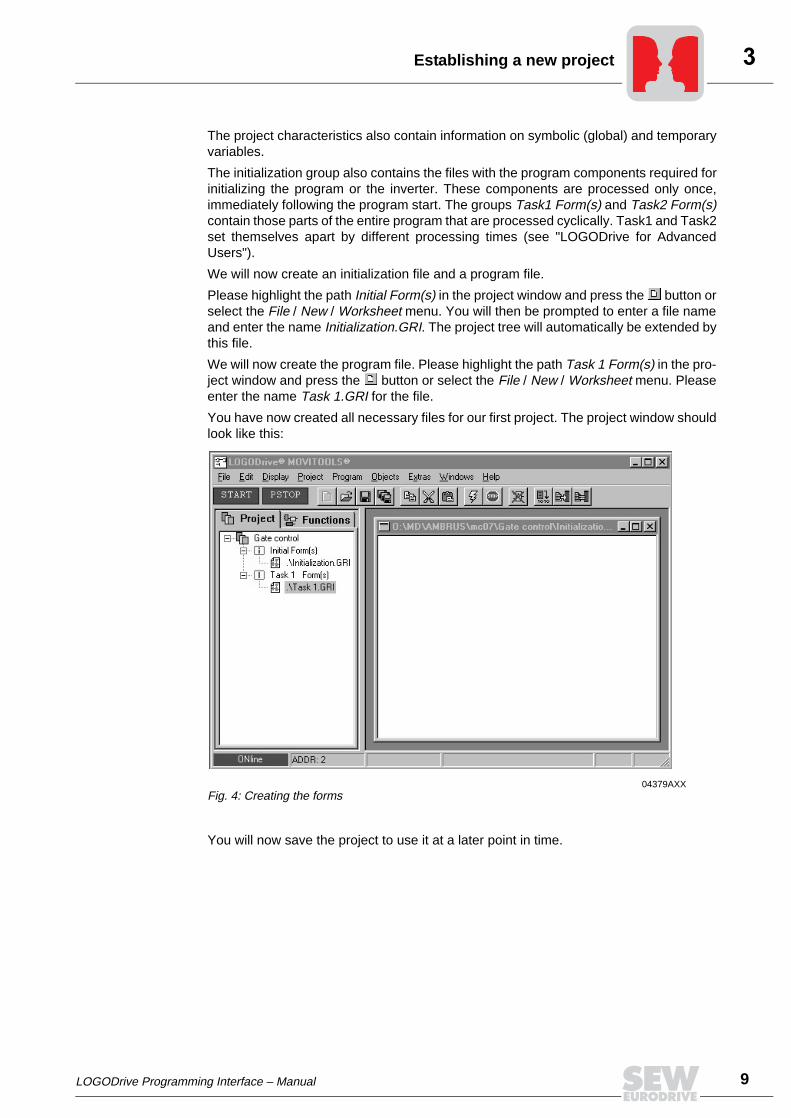
Please highlight the path Initial Form(s) in the project window and press the button orselect the File / New / Worksheet menu. You will then be prompted to enter a file nameand enter the name Initialization.GRI. The project tree will automatically be extended bythis file.
We will now create the program file. Please highlight the path Task 1 Form(s) in the pro-ject window and press the button or select the File / New / Worksheet menu. Pleaseenter the name Task 1.GRI for the file.
You have now created all necessary files for our first project. The project window shouldlook like this:
You will now save the project to use it at a later point in time.
04379AXXFig. 4: Creating the forms

10 LOGODrive Programming Interface – Manual
Editing the LOGODrive program
Press the "Save form" or "Save all forms" button or File / Save to save the project.
Please close the program with File / Close.
3.2 Editing the LOGODrive program
Start the LOGODrive program once again. The gate control program will be loadedautomatically, since it was open when the project was closed.
You will now write the program for a simple gate control routine to become familiar withthe other functions of the LOGODrive graphic programming interface.
Problem The program is to result in a simple gate control.
• A traffic light is red at the start and the gate is closed.
• The gate is supposed to open via a keyswitch.
• The traffic light is supposed to turn green within two (2) seconds after opening thegate.
• The gate should remain open for 20 seconds.
• The traffic light is supposed to turn red once again two (2) seconds prior to closingthe gate.
These requirements for this example result in the following input and output operandassignments:
Program genera-tion of the initiali-zation compo-nent
The variables of the initialization component are to be set to a defined initial state.
Double-click the Initialization.GRI file in the project window. This step opens an emptyform in which you can later connect the function blocks.
Click on the "Functions" tab in the project window to open the form. You will now see alist of all functions available in LOGODrive.
We now want to set the keyswitch, the gate and the traffic light to the initial state.
No. Type Name Description
1 Input operand
Keyswitch Simulation of the keyswitch0-1 edge: Open gate
2 Ouput operand
Gate Simulation of the gate0 = Gate closed1 = Gate open
3 Output operand
Red traffic light Simulation of the red traffic light0 = Red traffic light off1 = Red traffic light on
4 Output operand
Green traffic light Simulation of the green traffic light0 = Green traffic light off1 = Green traffic light on
LOGODrive Programming Interface – Manual 11
Editing the LOGODrive program
Adding a function block
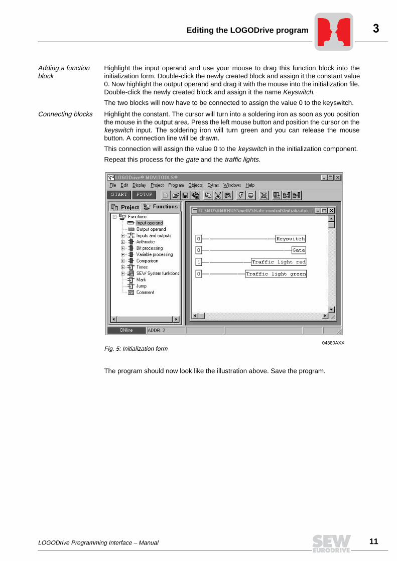
Highlight the input operand and use your mouse to drag this function block into theinitialization form. Double-click the newly created block and assign it the constant value0. Now highlight the output operand and drag it with the mouse into the initialization file.Double-click the newly created block and assign it the name Keyswitch.
The two blocks will now have to be connected to assign the value 0 to the keyswitch.
Connecting blocks Highlight the constant. The cursor will turn into a soldering iron as soon as you positionthe mouse in the output area. Press the left mouse button and position the cursor on thekeyswitch input. The soldering iron will turn green and you can release the mousebutton. A connection line will be drawn.
This connection will assign the value 0 to the keyswitch in the initialization component.
Repeat this process for the gate and the traffic lights.
The program should now look like the illustration above. Save the program.
04380AXXFig. 5: Initialization form

12 LOGODrive Programming Interface – Manual
Editing the LOGODrive program
Writing the program code
You will now have to write the program for the gate control by first opening theTask 1.GRI form.
The gate is to open as soon as the keyswitch detects a 0-1 edge.
We can use the TP encoder function block to open the gate.
Open the Times group in the Functions tab of the project window. You will find the TPfunction. Drag this block into the form.
Help function You can view a help function for this block by pressing the F1 key while highlighting thisfunction. The following Help window will be displayed:
05091AXXFig. 6: Help function for the TP function block
LOGODrive Programming Interface – Manual 13
Editing the LOGODrive program
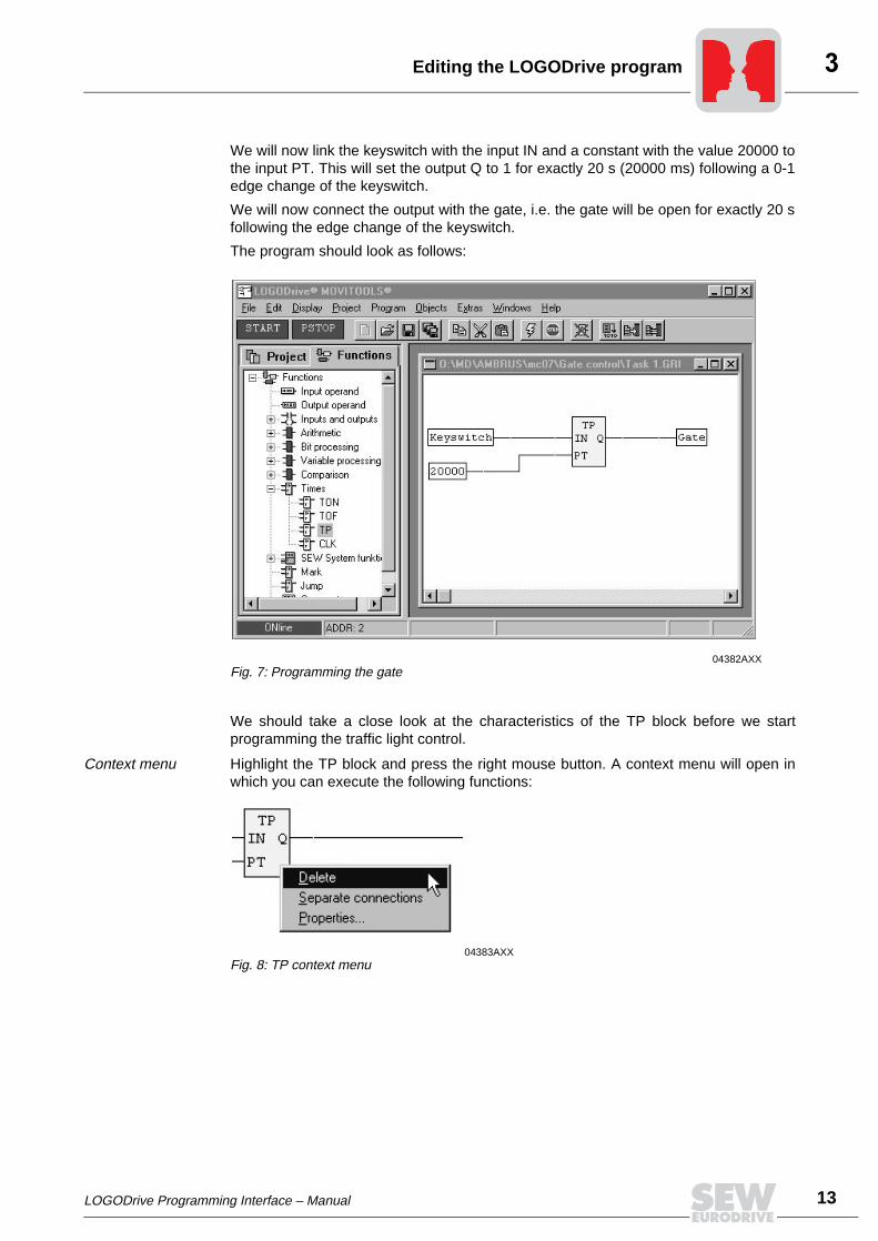
We will now link the keyswitch with the input IN and a constant with the value 20000 tothe input PT. This will set the output Q to 1 for exactly 20 s (20000 ms) following a 0-1edge change of the keyswitch.
We will now connect the output with the gate, i.e. the gate will be open for exactly 20 sfollowing the edge change of the keyswitch.
The program should look as follows:
We should take a close look at the characteristics of the TP block before we startprogramming the traffic light control.
Context menu Highlight the TP block and press the right mouse button. A context menu will open inwhich you can execute the following functions:
04382AXXFig. 7: Programming the gate
04383AXXFig. 8: TP context menu

14 LOGODrive Programming Interface – Manual
Editing the LOGODrive program
The inputs and outputs also have a context menu. Highlight the output of the TP functionblock and press the right mouse button.
You can delete the connection of the highlighted output or negate the output in thiscontext menu.
Negation of the output will place a minus sign in front of the output and the value will bewritten accordingly.
You can apply the same procedure to the inputs.
We will now have to control the traffic light.
04384AXXFig. 9: TP properties
Table 1: Context menu functions
Delete Deleting the block
Separate connections Separate all connections to/from this block
Properties Setting of initialization characteristics. The number of inputs for the TP block is fixed at two (2) and the number of outputs fixed at one (1).
04385AXXFig. 10: Context menu of output
04386AXXFig. 11: Negation of the output
LOGODrive Programming Interface – Manual 15
Editing the LOGODrive program
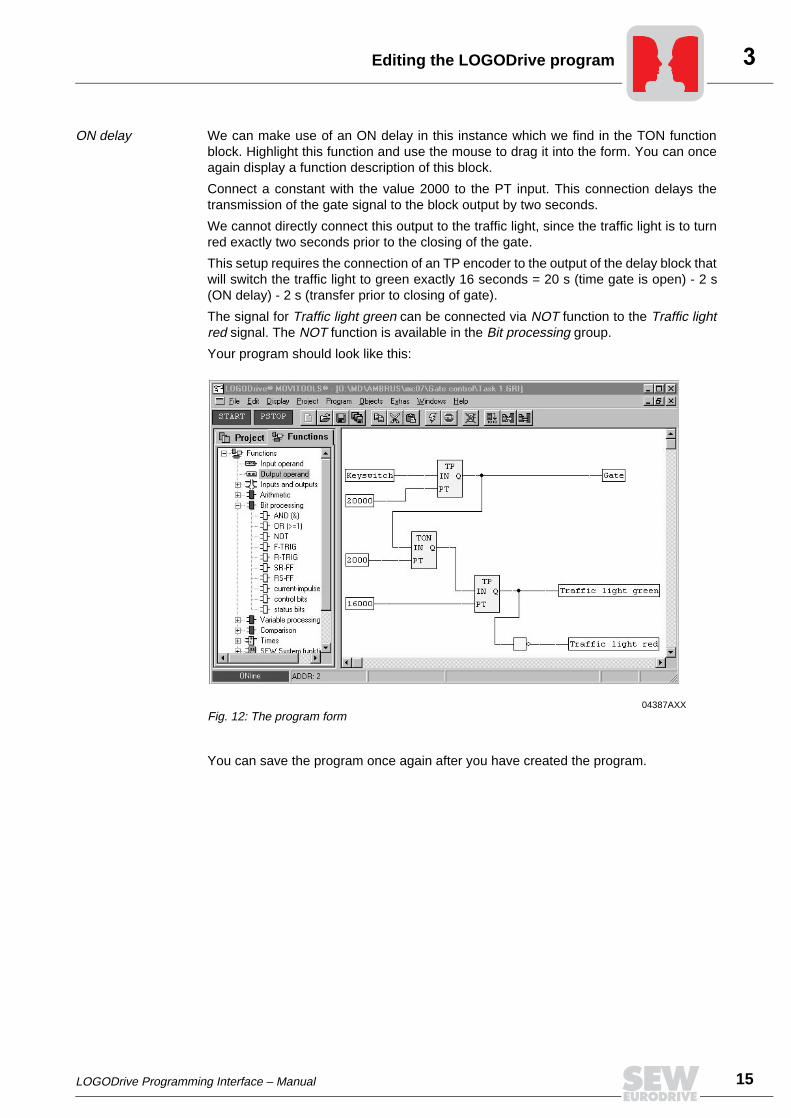
ON delay We can make use of an ON delay in this instance which we find in the TON functionblock. Highlight this function and use the mouse to drag it into the form. You can onceagain display a function description of this block.
Connect a constant with the value 2000 to the PT input. This connection delays thetransmission of the gate signal to the block output by two seconds.
We cannot directly connect this output to the traffic light, since the traffic light is to turnred exactly two seconds prior to the closing of the gate.
This setup requires the connection of an TP encoder to the output of the delay block thatwill switch the traffic light to green exactly 16 seconds = 20 s (time gate is open) - 2 s(ON delay) - 2 s (transfer prior to closing of gate).
The signal for Traffic light green can be connected via NOT function to the Traffic lightred signal. The NOT function is available in the Bit processing group.
Your program should look like this:
You can save the program once again after you have created the program.
04387AXXFig. 12: The program form

16 LOGODrive Programming Interface – Manual
Compiling the program
4 Compiling, Loading and Starting the LOGODrive ProgramIn this section, you will compile the generated program, load it into the inverter andexecute it.
Download procedure
There are two ways to download a programmed project. The program functionality is de-termined only by the compiled source code. The option to save the graphic in the inver-ter makes it possible for the user to quickly become familiar with the implemented projectonce again, even after an extended period of time.
Saving the source code
The source code is transmitted to the inverter via the download button or the "Program"/"Translate and load" menu bar, i.e. the graphic is not saved in the inverter but only thesource code.
This function is very useful in case the program functions are constantly tested duringthe project development stage and when it is unnecessary to save the graphic in theinverter every time.
Saving graphic The graphic program file will be transmitted via the "Project" /"Download" menu bar, i.e.the source code and the graphic are saved in the inverter in case of error-free compiling.This function is very useful when the entire project is to be saved in the inverter at theend of the program development process.
4.1 Compiling the program
We now want to compile the LOGODrive program. Please press the button. This stepensures that you are automatically saving and subsequently compiling the program. Thecompiled code will be saved in the frequency inverter.
04410AXXFig. 13: Result of the compiler
LOGODrive Programming Interface – Manual 17
Compiling the program
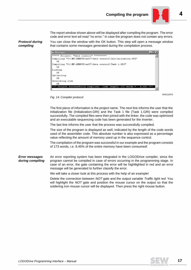
The report window shown above will be displayed after compiling the program. The errorcode and error text wil read "no error," in case the program does not contain any errors.
Protocol during compiling
You can close the window with the OK button. This step will open a message windowthat contains some messages generated during the compilation process.
The first piece of information is the project name. The next line informs the user that theinitialization file (Initialization.GRI) and the Task 1 file (Task 1.GRI) were compiledsuccessfully. The compiled files were then joined with the linker, the code was optimizedand an executable sequencing code has been generated for the inverter.
The last line informs the user that the process was successfully compiled.
The size of the program is displayed as well, indicated by the length of the code wordsused of the assembler code. This absolute number is also expressed as a percentagevalue reflecting the amount of memory used up in the sequence control.
The compilation of the program was successful in our example and the program consistsof 173 words, i.e. 8.45% of the entire memory have been consumed!
Error messages during compiling
An error reporting system has been integrated in the LOGODrive compiler, since theprogram cannot be compiled in case of errors occurring in the programming stage. Incase of an error, the gate containing the error will be hightlighted in red and an errormessage will be generated to further classify the error.
We will take a closer look at this process with the help of an example!
Delete the connection between NOT gate and the output variable Traffic light red. Youwill highlight the NOT gate and position the mouse cursor on the output so that thesoldering iron mouse cursor will be displayed. Then press the right mouse button.
04411AXXFig. 14: Compiler protocol
18 LOGODrive Programming Interface – Manual
Compiling the program
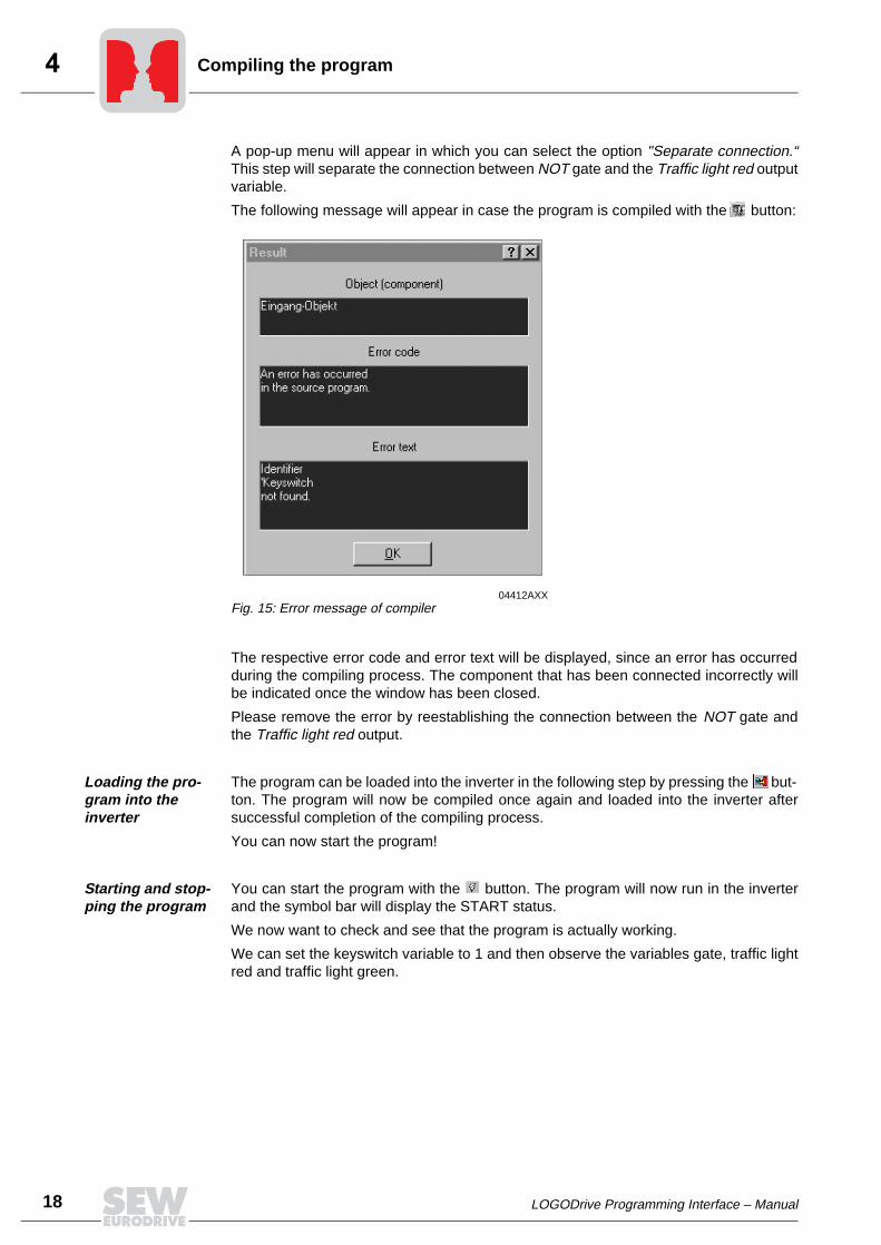
A pop-up menu will appear in which you can select the option "Separate connection.“This step will separate the connection between NOT gate and the Traffic light red outputvariable.
The following message will appear in case the program is compiled with the button:
The respective error code and error text will be displayed, since an error has occurredduring the compiling process. The component that has been connected incorrectly willbe indicated once the window has been closed.
Please remove the error by reestablishing the connection between the NOT gate andthe Traffic light red output.
Loading the pro-gram into the inverter
The program can be loaded into the inverter in the following step by pressing the but-ton. The program will now be compiled once again and loaded into the inverter aftersuccessful completion of the compiling process.
You can now start the program!
Starting and stop-ping the program
You can start the program with the button. The program will now run in the inverterand the symbol bar will display the START status.
We now want to check and see that the program is actually working.
We can set the keyswitch variable to 1 and then observe the variables gate, traffic lightred and traffic light green.
04412AXXFig. 15: Error message of compiler

LOGODrive Programming Interface – Manual 19
Upload
This step requires that you open the variable window with Display / All Variables. Youwill overwrite the variable H350 Keyswitch with the value "1" and observe the variablesH351 Gate, H352 Traffic light red and H353 Traffic light green.
The functionality of the variable windows will be explained in more detail in the next step.
We will now stop the program by pressing the button. The status bar will once againdisplay PSTOP (program stop).
Comparing the programs
Close the LOGODrive compiler and start it once again.
The previous program will be saved in the inverter. You may not remember if the pro-gram in the inverter is the same as the one displayed in the LOGODrive compiler.
You can compare the two programs with a comparing function by pressing the button.A dialog window will inform you if these programs are identical or not.
The programs in our example are identical and the following window will be displayed:
4.2 Upload
When a program is loaded from the inverter to the PC, the source code is first comparedwith the graphic data. The project will be displayed in case the data are identical. Awarning message will appear and the graphic data displayed in case the data are notidentical.
4.3 End LOGODrive
In case you end the LOGODrive application, you will first be asked if the source codehas been changed and loaded into the inverter, i.e. the source code and the graphic dataare different in the inverter. If this should be the case, you will be asked if you want totransmit the graphic data into the inverter.
04413AXXFig. 16: Comparison of programs
20 LOGODrive Programming Interface – Manual
Variable windows
5 Monitoring FunctionsWe will now change and monitor the variables to check if the desired functions havebeen executed.
5.1 Variable windows
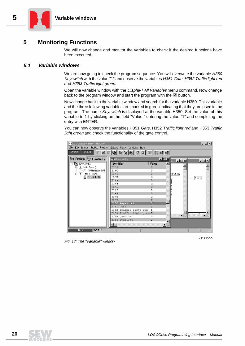
We are now going to check the program sequence. You will overwrite the variable H350Keyswitch with the value "1" and observe the variables H351 Gate, H352 Traffic light redand H353 Traffic light green.
Open the variable window with the Display / All Variables menu command. Now changeback to the program window and start the program with the button.
Now change back to the variable window and search for the variable H350. This variableand the three following variables are marked in green indicating that they are used in theprogram. The name Keyswitch is displayed at the variable H350. Set the value of thisvariable to 1 by clicking on the field "Value," entering the value "1" and completing theentry with ENTER.
You can now observe the variables H351 Gate, H352 Traffic light red and H353 Trafficlight green and check the functionality of the gate control.
04414AXXFig. 17: The "Variable" window

LOGODrive Programming Interface – Manual 21
Display selected variables
5.2 Display selected variables
We do not operate with the internal variable numbering system H0-H511 in our sampleprogram, but with symbolic identifiers (e.g. Keyswitch). The compiler attributes a fixedvariable to these symbolic identifiers, resulting in variables in this range and starting withH350 in our example.
It does not matter to which physical variables the individual values have been assignedin our example. A special window has been created to observe the symbolic variablesin which the selected variables will be displayed.
Open the window via Display / Selected variables / Display. You must now define thevariables you would like to see displayed.
Select the menu point Display / Selected variables / Compile. A selection dialog windowwill open in which you can select the variables you would like to have displayed.
04115AXXFig. 18: Selecting variables
22 LOGODrive Programming Interface – Manual
Display selected variables
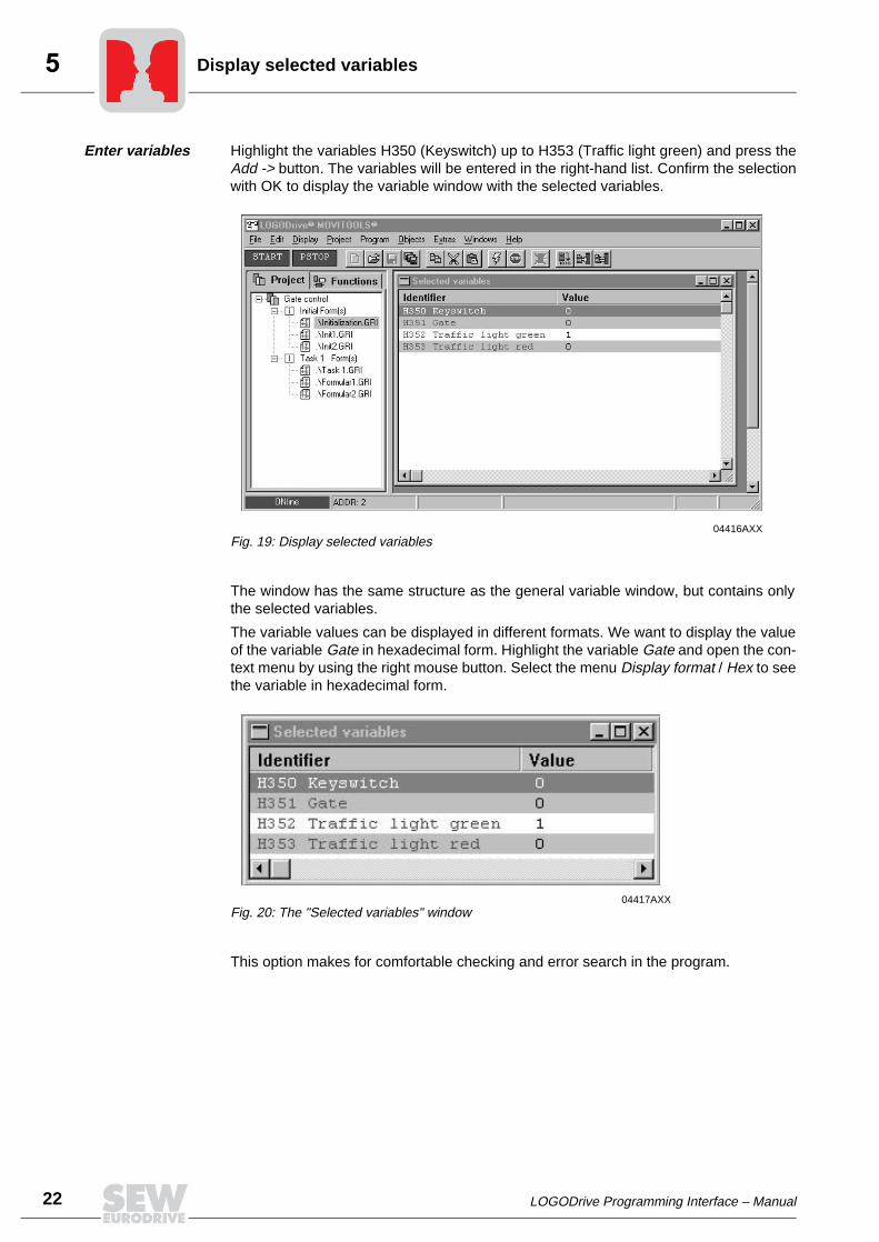
Enter variables Highlight the variables H350 (Keyswitch) up to H353 (Traffic light green) and press theAdd -> button. The variables will be entered in the right-hand list. Confirm the selectionwith OK to display the variable window with the selected variables.
The window has the same structure as the general variable window, but contains onlythe selected variables.
The variable values can be displayed in different formats. We want to display the valueof the variable Gate in hexadecimal form. Highlight the variable Gate and open the con-text menu by using the right mouse button. Select the menu Display format / Hex to seethe variable in hexadecimal form.
This option makes for comfortable checking and error search in the program.
04416AXXFig. 19: Display selected variables
04417AXXFig. 20: The "Selected variables" window

LOGODrive Programming Interface – Manual 23
Using comments
6 Program DocumentationThe documentation is an important aspect when creating a program. The better the do-cumentation, the faster another person can become familiar with a particular program.
You can insert comments within a LOGODrive program and insert this commentelement at any position to document your program.
There is also a print function which lets you print a formated worksheet.
6.1 Using comments
We now want to insert a comment in our program containing the following text:
----------------------------------------------Gate control:Keyswitch ON (=1) -->1. Gate opens2. Traffic light turns green after 2s3. Traffic light turns red again after an additional 16s4. Gate closes after another 2s have elapsed----------------------------------------------
The existing connection will have to be relocated since the text is rather comprehensive.
Draw a circle around all modules to highlight them. You can now position the mouse ona particular module (the mouse cursor turns into small crossed arrows). You can movethe entire frame by pressing the left mouse button and moving the mouse at the sametime.
You can now select the comment from the list of functions and position it in the freespace on the worksheet. Double-clicking the element will open a dialog window in whichyou can enter the desired comment.
24 LOGODrive Programming Interface – Manual
Printing a sample program
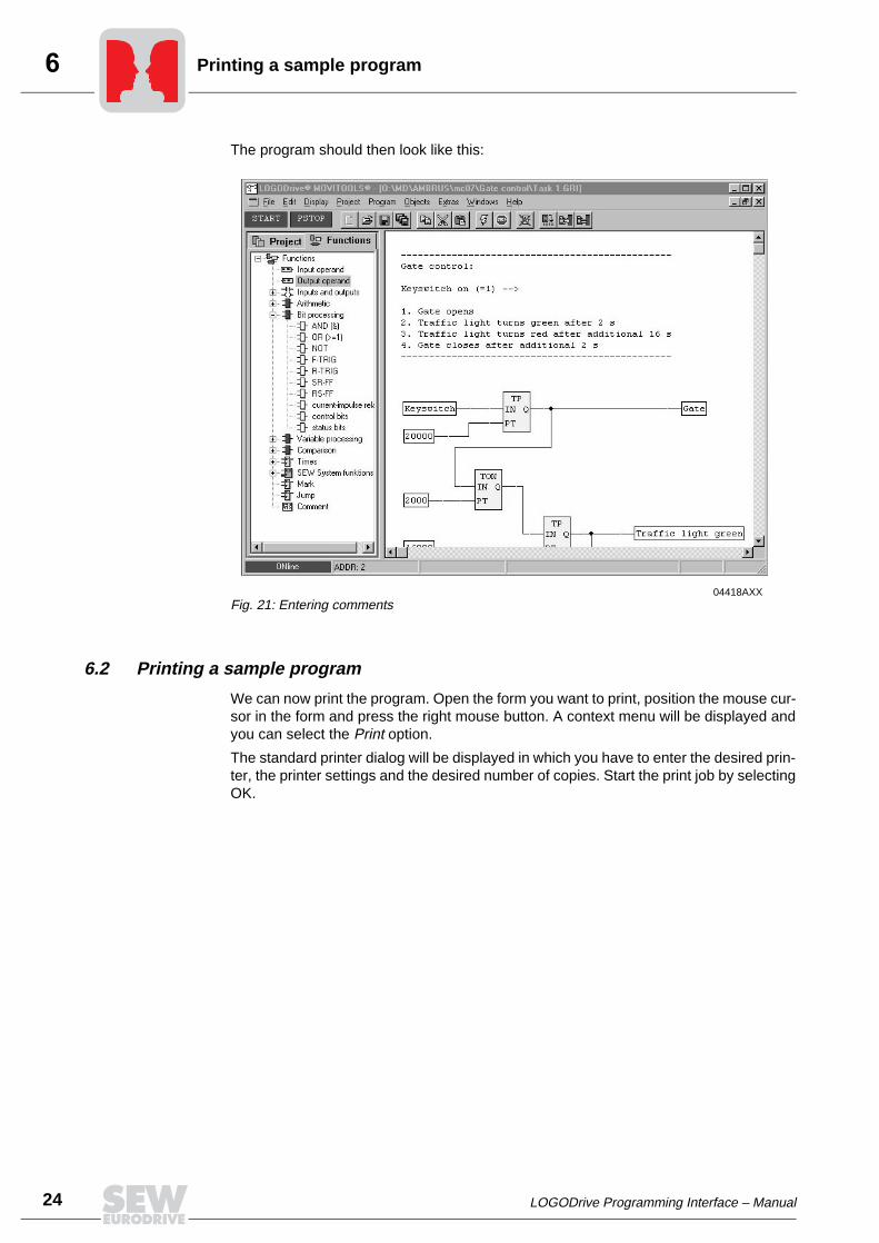
The program should then look like this:
6.2 Printing a sample program
We can now print the program. Open the form you want to print, position the mouse cur-sor in the form and press the right mouse button. A context menu will be displayed andyou can select the Print option.
The standard printer dialog will be displayed in which you have to enter the desired prin-ter, the printer settings and the desired number of copies. Start the print job by selectingOK.
04418AXXFig. 21: Entering comments

LOGODrive Programming Interface – Manual 25
Changing the project characteristics
7 LOGODrive for Advanced UsersThis section describes some of the more advanced characteristics and functions of theLOGODrive program.
7.1 Changing the project characteristics
We started this process by creating a new project and had to determine the programparts we wanted to generate. We created
• an initialization component: Initial Form(s)
• and Task 1: Task 1 Form(s).
We also had to indicate the project name (Gate control).
You will now have to select the Project / Properties menu to change these project-specific characteristics.
The project properties window will appear once again. You can now change the proper-ties according to your needs and accept the changes with OK.
04419AXXFig. 22: Changing the project properties
26 LOGODrive Programming Interface – Manual
Deleting redundant variables
7.2 Deleting redundant variables
A function has been implemented in the LOGODrive compiler that enables the user todelete all redundant variables.
Redundant variables are those variables that are not connected to a function block oranother variable, i.e. function blocks that do not generate a program code.
This situation could occur during the programming process in case you delete a functionblock in the form but forget to also delete the input variables.
The compiler will issue an error report in this instance, since it has detected a variablethat is not connected to another element.
Activate the desired form to delete all redundant variables prior to compiling and executethe Edit / Delete redundant menu command.
You can also activate this function via the context menu (press right mouse button in thecorresponding form) and execute the Delete redundant objects menu selection.
You can expand the form by some input variables or constants to check this function andthen select the Delete redundant objects command. You can now observe that thesevariables and constants are deleted.
7.3 Program processing
It is very important for the programming process to know the sequence in which the pro-grammed networks of the program will have to be processed.
There are some rules for this sequence:
• The forms created in the project path will be processed in a sequence from top tobottom, i.e. the initialization forms will be executed first, followed by the Task 1 orTask 2 forms.
• The forms within a form group are processed in a sequence from top to bottom.
• The networks within a form will be processed from left to right and from top to bottom.
Example for a sequence
We are going to expand our example by some forms to demonstrate the processing ofthe program and the networks with the help of this example.
Expand your project in the form group Initial Form(s) by the forms Init1.GRI, Init2.GRIand in the from group Task 1 Form(s) by the forms Formular1.GRI and Formular2.GRI.
LOGODrive Programming Interface – Manual 27
Program processing
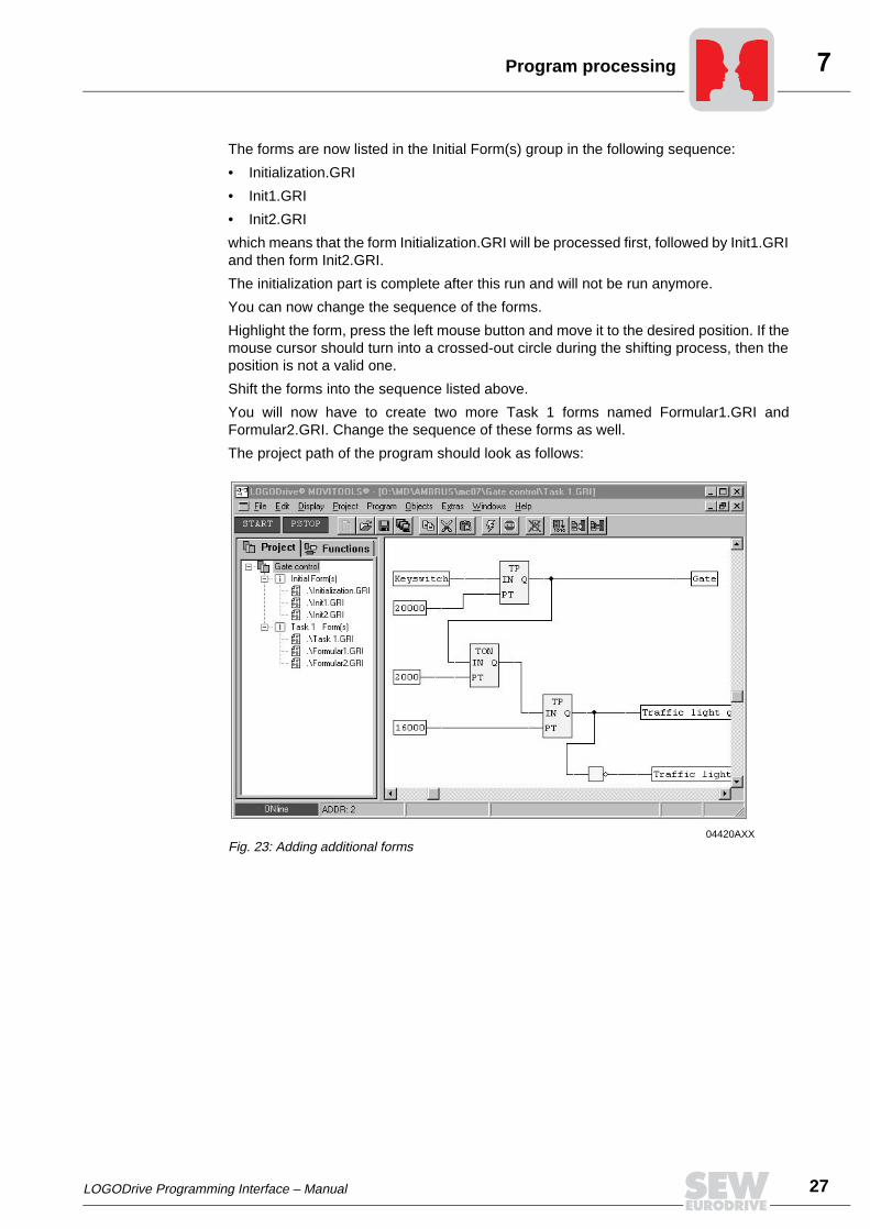
The forms are now listed in the Initial Form(s) group in the following sequence:
• Initialization.GRI
• Init1.GRI
• Init2.GRI
which means that the form Initialization.GRI will be processed first, followed by Init1.GRIand then form Init2.GRI.
The initialization part is complete after this run and will not be run anymore.
You can now change the sequence of the forms.
Highlight the form, press the left mouse button and move it to the desired position. If themouse cursor should turn into a crossed-out circle during the shifting process, then theposition is not a valid one.
Shift the forms into the sequence listed above.
You will now have to create two more Task 1 forms named Formular1.GRI andFormular2.GRI. Change the sequence of these forms as well.
The project path of the program should look as follows:
04420AXXFig. 23: Adding additional forms

28 LOGODrive Programming Interface – Manual
Program processing
We now want to take a closer look at the program sequence. The forms will beprocessed in the following sequence:
Processing of the networks within a form takes place from left to right and from top tobottom. This means that in our example the value of the variable gate is calculated first,followed by the value of traffic light green and traffic light red being the last value that iscalculated.
Table 2: Program sequence
↓
Initialization.gri
↓
Init1.gri
↓
Init2.gri
↓
↓
Task 1 Form.gri
↓
Form1.gri
↓
Form2.gri
↓
04421AXXFig. 24: Processing of networks
LOGODrive Programming Interface – Manual 29
Program processing
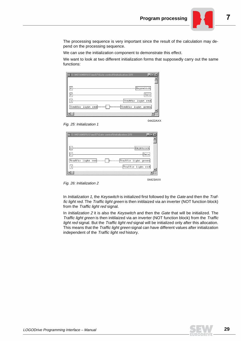
The processing sequence is very important since the result of the calculation may de-pend on the processing sequence.
We can use the initialization component to demonstrate this effect.
We want to look at two different initialization forms that supposedly carry out the samefunctions:
In Initialization 1, the Keyswitch is initialized first followed by the Gate and then the Traf-fic light red. The Traffic light green is then initilaized via an inverter (NOT function block)from the Traffic light red signal.
In Initialization 2 it is also the Keyswitch and then the Gate that will be initialized. TheTraffic light green is then initilaized via an inverter (NOT function block) from the Trafficlight red signal. But the Traffic light red signal will be initialized only after this allocation.This means that the Traffic light green signal can have different values after initializationindependent of the Traffic light red history.
04422AXXFig. 25: Initialization 1
04423AXXFig. 26: Initialization 2

30 LOGODrive Programming Interface – Manual
Updating of inputs/outputs
If the Traffic light red signal was 0 at the stop, Traffic light green will be initialized with 1and in the next line Traffic light red will also be initialized with 1. The result will be aninvalid state in which both signals are 1!
You see that the processing sequence of the networks is extremely important.
7.4 Updating of inputs/outputs
The processing times are very important as well. The outputs and variables in the inver-ter sequence control are updated exactly at that time when the corresponding value iscalculated by the network. The inputs are updated asynchronously to the programprocessing.
This characteristic differentiates these sequence controls from a PLC programthat uses a process image and updates the outputs only after each program run!
You can create a process image by noting all relevant input sizes (process data andinputs ...) at the beginning of the cyclical processing sequence (e.g. as first worksheetin Task 1 Form(s) section) and using it in the remaining program sequence. The sameprocedure applies to the output values. Write the outputs you want to place, processdata, etc. into variables and include a final worksheet in the cycle that sets the physicaloutputs.
7.5 Processing times
The proceccing times of the function blocks depends on the type of function block.
There are functions whose function is directly implemented in the sequence control ofthe inverter (e.g. AND, OR, NOT, ADD, etc). If they use only two (2) inputs, these func-tions will be processed within 1ms (Task 1) or 0.5 ms (Task 2).
Other functions, such as the ON delay TON, require several milliseconds for their exe-cution. This characteristic can be attributed to the fact that the functions have to betranslated into separate internal commands with each of these commands requiring 1ms(Task1) or 0.5 ms (Task2).
7.6 Processing times for the entire program
Please note that in case timer blocks (ON delay, OFF delay, etc.) have been incorpora-ted into a LOGODrive program, the processing time of the entire program has to benegligible as far as the time period is concerned that is used in the respective block.
LOGODrive Programming Interface – Manual 31
Using TASK 2
Here a brief example:
The program contains an ON delay. The program processing time has been estimatedat approximately 20 ms. The accurate value for the ON delay is 20 ms in this case.
If you are using an ON delay of 1s, the ON delay can vary by 20 ms, i.e. it can be in therange of 1 s - 1.02 s.
The inaccuracy percentage will decrease when a larger ON delay period is selected.
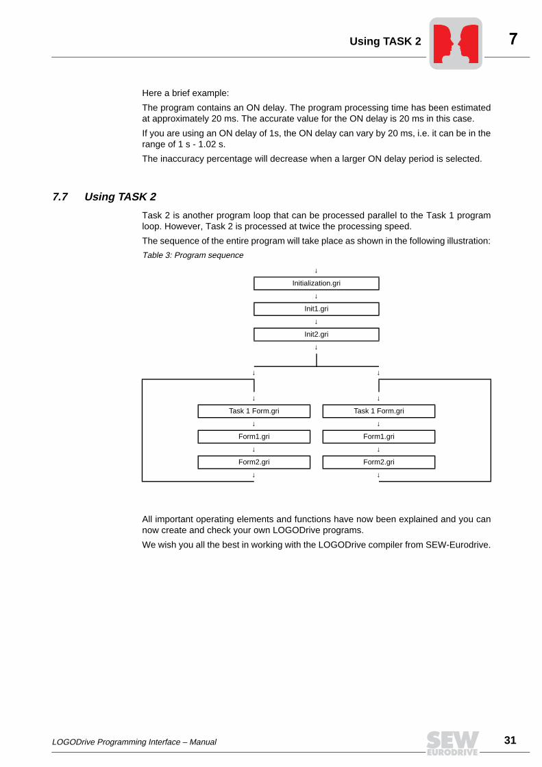
7.7 Using TASK 2
Task 2 is another program loop that can be processed parallel to the Task 1 programloop. However, Task 2 is processed at twice the processing speed.
The sequence of the entire program will take place as shown in the following illustration:
All important operating elements and functions have now been explained and you cannow create and check your own LOGODrive programs.
We wish you all the best in working with the LOGODrive compiler from SEW-Eurodrive.
Table 3: Program sequence
↓
Initialization.gri
↓
Init1.gri
↓
Init2.gri
↓
↓ ↓
↓ ↓
Task 1 Form.gri Task 1 Form.gri
↓ ↓
Form1.gri Form1.gri
↓ ↓
Form2.gri Form2.gri
↓ ↓
32 LOGODrive Programming Interface – Manual
Simple motor control
8 Examples
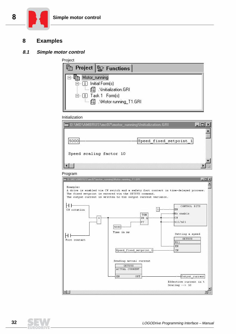
8.1 Simple motor control
Project
Initialization
Program
LOGODrive Programming Interface – Manual 33
Current detection
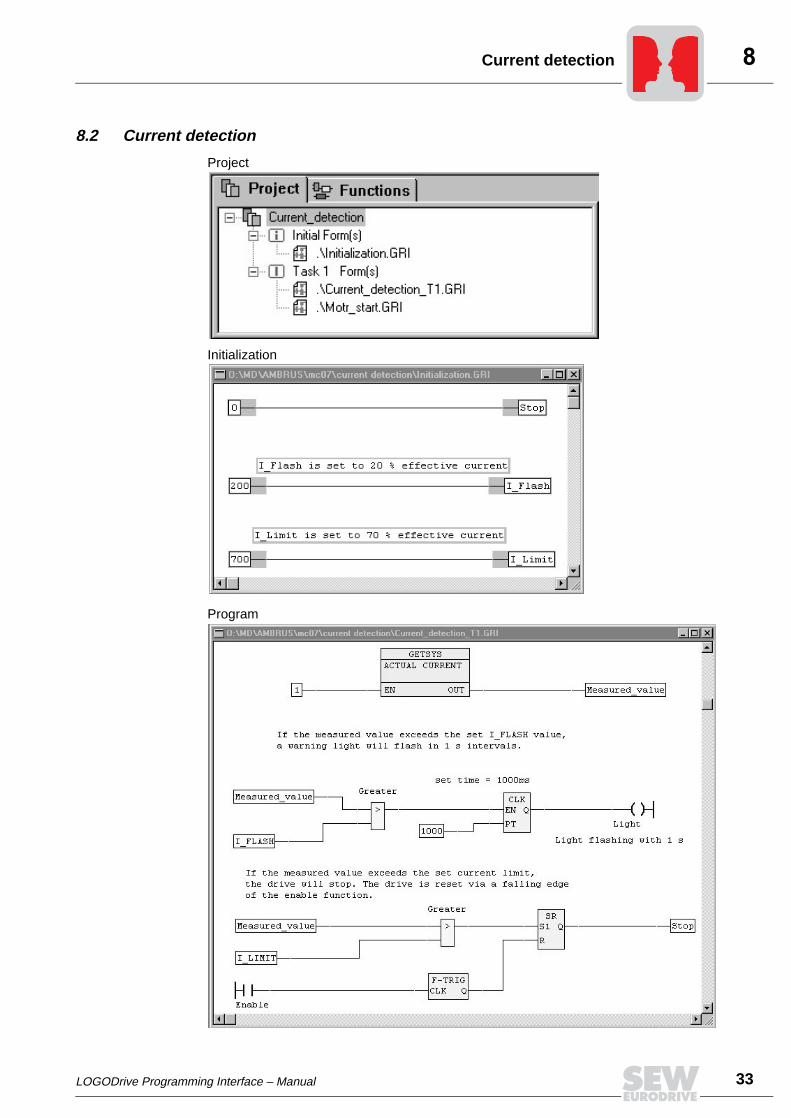
8.2 Current detection
Project
Initialization
Program

34 LOGODrive Programming Interface – Manual
Current detection
Start conditions for drive
LOGODrive Programming Interface – Manual 35
Operands
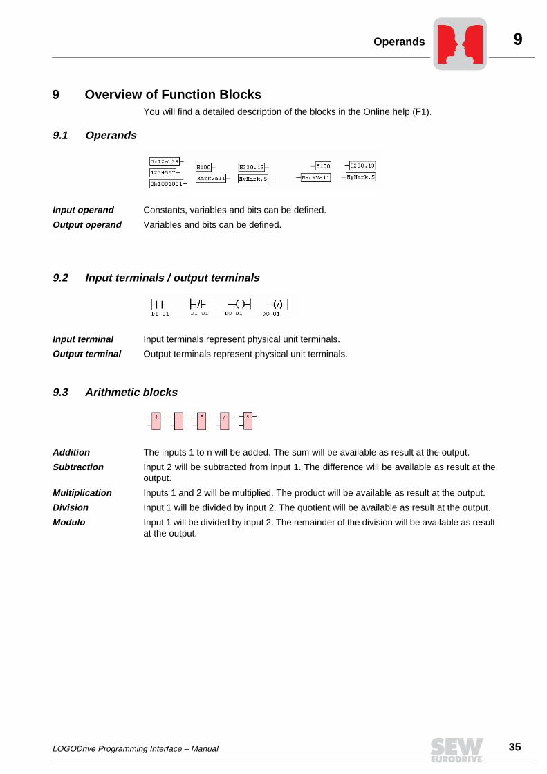
9 Overview of Function BlocksYou will find a detailed description of the blocks in the Online help (F1).
9.1 Operands
Input operand Constants, variables and bits can be defined.
Output operand Variables and bits can be defined.
9.2 Input terminals / output terminals
Input terminal Input terminals represent physical unit terminals.
Output terminal Output terminals represent physical unit terminals.
9.3 Arithmetic blocks
Addition The inputs 1 to n will be added. The sum will be available as result at the output.
Subtraction Input 2 will be subtracted from input 1. The difference will be available as result at theoutput.
Multiplication Inputs 1 and 2 will be multiplied. The product will be available as result at the output.
Division Input 1 will be divided by input 2. The quotient will be available as result at the output.
Modulo Input 1 will be divided by input 2. The remainder of the division will be available as resultat the output.
36 LOGODrive Programming Interface – Manual
Bit processing
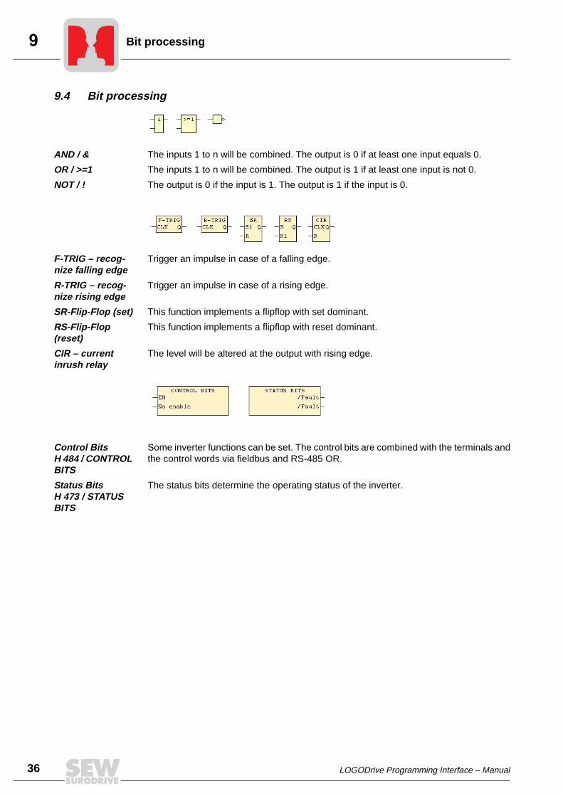
9.4 Bit processing
AND / & The inputs 1 to n will be combined. The output is 0 if at least one input equals 0.
OR / >=1 The inputs 1 to n will be combined. The output is 1 if at least one input is not 0.
NOT / ! The output is 0 if the input is 1. The output is 1 if the input is 0.
F-TRIG – recog-nize falling edge
Trigger an impulse in case of a falling edge.
R-TRIG – recog-nize rising edge
Trigger an impulse in case of a rising edge.
SR-Flip-Flop (set) This function implements a flipflop with set dominant.
RS-Flip-Flop (reset)
This function implements a flipflop with reset dominant.
CIR – current inrush relay
The level will be altered at the output with rising edge.
Control Bits H 484 / CONTROL BITS
Some inverter functions can be set. The control bits are combined with the terminals andthe control words via fieldbus and RS-485 OR.
Status Bits H 473 / STATUS BITS
The status bits determine the operating status of the inverter.

LOGODrive Programming Interface – Manual 37
Variable processing
9.5 Variable processing
And / VAND / V& The inputs will be AND-combined bit by bit. The output is 0 if at least one of the inputsequals 0.
Or / VOR / V>=1 The inputs will be OR-combined bit by bit. The output is 0 if all inputs equal 0.
Exclusive-Or / VXOR / V=!
The inputs will be XOR-combined bit by bit. The output is 0 if all inputs do not equal 0.
Multiplexer / MUX Several inputs are compared with a comparison value. If one of the inputs correspondswith this comparison value, the output will be set to this value.
SHL (<<) / Bit shift left
The content of one variable is shifted to the left bit by bit. Any space that will becomeavailable through this process will be filled with a zero.
SHR (>>) / Bit shift right
The content of one variable is shifted to the right bit by bit. Any space that will becomeavailable through this process will be filled with a zero.
Latch These are memory blocks that will transmit connected dates to the output in either aedge-sensitive or state-sensitive manner.
Multiplexer / MUX Several inputs can be attributed to the output via a comparison value, while it is also pos-sible to enter a default value.
BSET (Set bit) Bits can be set or deleted from a connected value.
BSEL (Select bit) A connected value will be separated into its individual bits.
9.6 Comparison blocks
Greater than / GT / >
If input 1 is greater than input 2, the output will be 1, otherwise 0.
Greater or equal to/ GE / >=
If input 1 is greater than or equal to input 2, the output will be 1, otherwise 0.
Less than/ LT / < If input 1 is less than input 2, the output will be 1, otherwise 0.
Less than equal to / LE / <=
If input 1 is less than or equal to input 2, the output will be 1, otherwise 0.
Equal to / EQ / == If input 1 is equal to input 2, the output will be 1, otherwise 0.
Not equal to / NE / <>
If input 1 is not equal to input 2, the output will be 1, otherwise 0.
38 LOGODrive Programming Interface – Manual
Time blocks
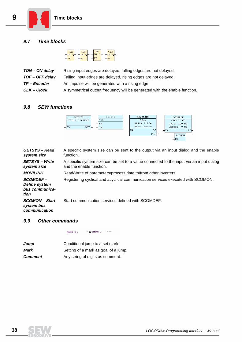
9.7 Time blocks
TON – ON delay Rising input edges are delayed, falling edges are not delayed.
TOF – OFF delay Falling input edges are delayed, rising edges are not delayed.
TP – Encoder An impulse will be generated with a rising edge.
CLK – Clock A symmetrical output frequency will be generated with the enable function.
9.8 SEW functions
GETSYS – Read system size
A specific system size can be sent to the output via an input dialog and the enablefunction.
SETSYS – Write system size
A specific system size can be set to a value connected to the input via an input dialogand the enable function.
MOVILINK Read/Write of parameters/process data to/from other inverters.
SCOMDEF – Define system bus communica-tion
Registering cyclical and acyclical communication services executed with SCOMON.
SCOMON – Start system bus communication
Start communication services defined with SCOMDEF.
9.9 Other commands
Jump Conditional jump to a set mark.
Mark Setting of a mark as goal of a jump.
Comment Any string of digits as comment.

LOGODrive Programming Interface – Manual 39
10 Index
A
Adding a function block 11Arithmetic blocks 35
B
Bit processing 36
C
Changing the project characteristics 25Comments 23Comparing the programs 19Comparison 19Comparison blocks 37Compiling 16Connect serial interface 5Connecting blocks 11Connection serial interface 5Context menu 13
D
Deleting 26Deleting redundant variables 26Deleting variables 26Description 6Display selected variables 21Documentation 23Download 16
E
Editing 10Editing program 10Entering data 8Error messages during compiling 17Establishing a new project 8Examples 32
H
Help function 12
I
Initialization component 10Input terminals 35
L
Loading 18Loading the program 18
M
Monitoring functions 20
O
Online help 12Operands 35Output terminals 35
Overview of function blocks 35
P
Prerequisites 4Printing 24Printing program 24Processing times function blocks 30Processing times program 30Program documentation 23Program processing 26Protocol during compiling 17
S
SEW functions 38Start 5, 16, 18Starting program 18Stop 18Stopping program 18
T
Task 2 31Time blocks 37
U
Updating inputs 30Updating inputs/outputs 30Updating outputs 30Upload 19
V
Variable display user-specific 21Variable processing 37Variable windows 20
W
Writing the program code 12

SEW-EURODRIVE GmbH & Co · P.O. Box 3023 · D-76642 Bruchsal/Germany · Phone +49-7251-75-0Fax +49-7251-75-1970 · http://www.sew-eurodrive.com · [email protected]