edge™ mav control system project # p09122 erik bellandi – project manager ben wager – lead...
Post on 20-Dec-2015
215 views
TRANSCRIPT

EDGE™
MAV Control SystemProject # P09122
Erik Bellandi – Project ManagerBen Wager – Lead Engineer
Garrett Argenna – Mechanical EngineeringMichael Pepen – Electrical Engineering
Tahar Allag – Electrical EngineeringRamon Campusano – Computer Engineering
Stephen Nichols – Computer Engineering
EDGE™
Contents
• Background
• Project Planning
• Concept Development– Control System– Logic Controller– Sensors– Test Stand
• Future Work
• Risk Assessment
EDGE™
Background
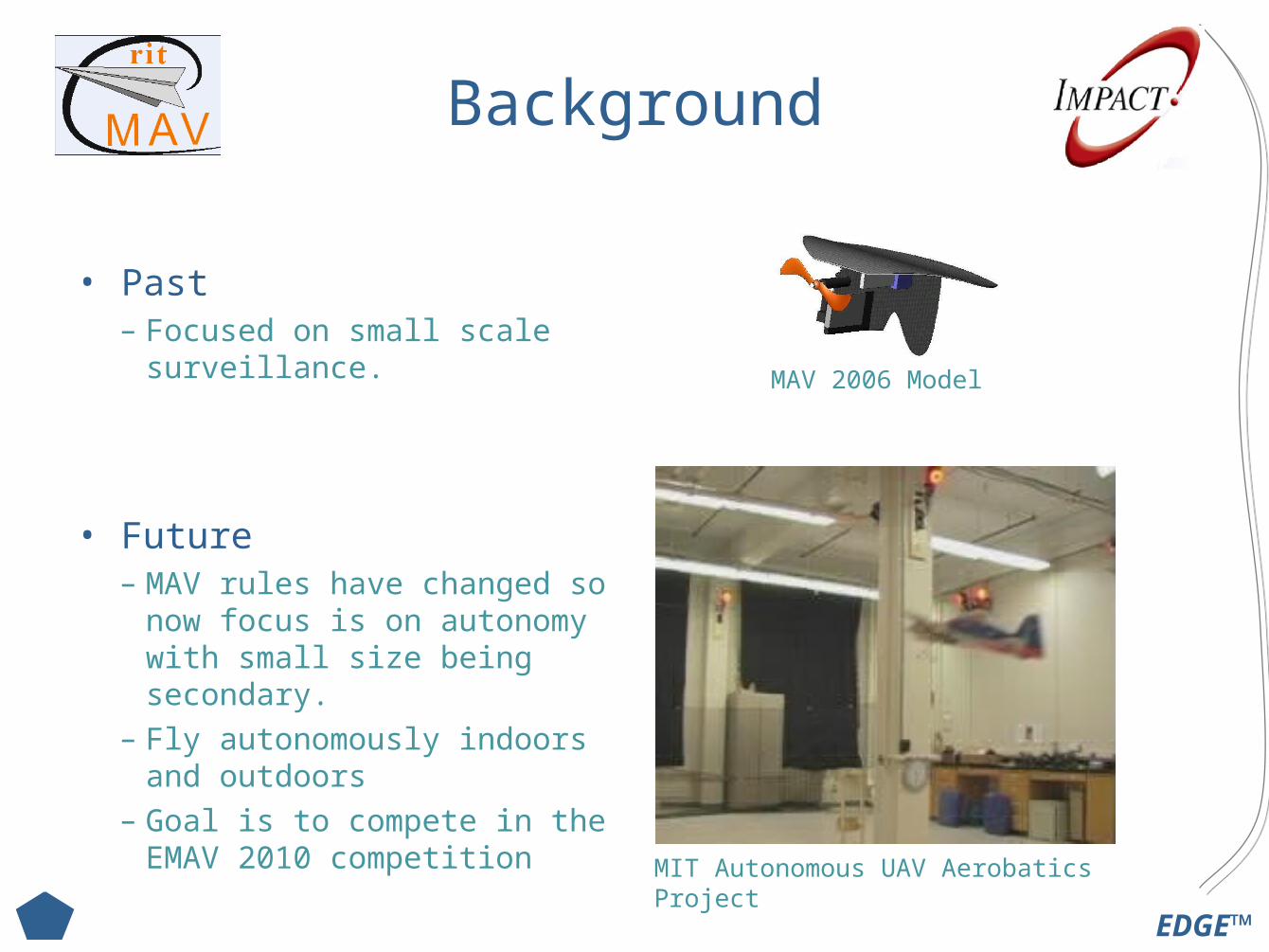
• Past – Focused on small scale
surveillance.
• Future– MAV rules have changed so
now focus is on autonomy with small size being secondary.
– Fly autonomously indoors and outdoors
– Goal is to compete in the EMAV 2010 competition
MIT Autonomous UAV Aerobatics Project
MAV 2006 Model

EDGE™
Project Planning
EDGE™
Project Overview & Deliverables
Product Description / Project OverviewTo design and build a flight control system for the Micro Aerial Vehicle, that will most quickly lead to a fully autonomous system.
Key Business Goals / Project Deliverables Primary Goals:– Make the MAV as autonomous as possible.
• Stabilize Flight• Adaptable• Fully Tested and Integrate with Platform
Secondary Business Goal:– Able to compete in the 2010 EMAV Competition.
EDGE™
Identify Customer Needs
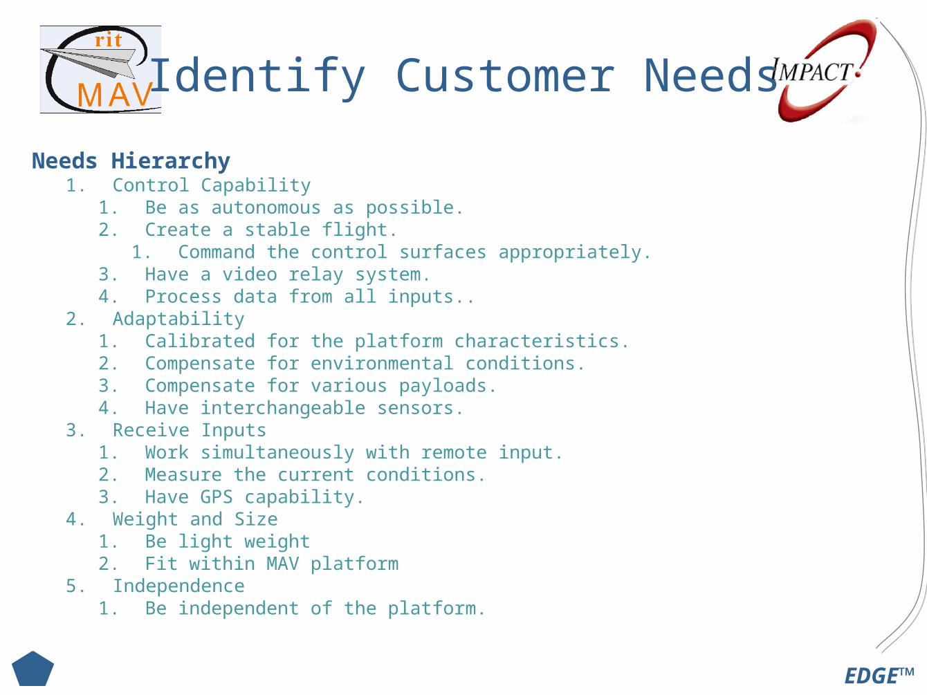
Needs Hierarchy1. Control Capability
1. Be as autonomous as possible.2. Create a stable flight.
1. Command the control surfaces appropriately.3. Have a video relay system.4. Process data from all inputs..
2. Adaptability1. Calibrated for the platform characteristics.2. Compensate for environmental conditions.3. Compensate for various payloads.4. Have interchangeable sensors.
3. Receive Inputs1. Work simultaneously with remote input.2. Measure the current conditions.3. Have GPS capability.
4. Weight and Size1. Be light weight2. Fit within MAV platform
5. Independence1. Be independent of the platform.
EDGE™
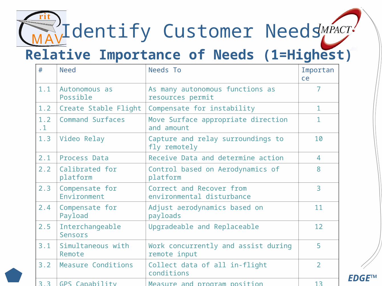
Identify Customer NeedsRelative Importance of Needs (1=Highest)
# Need Needs To Importance
1.1 Autonomous as Possible As many autonomous functions as resources permit
7
1.2 Create Stable Flight Compensate for instability 1
1.2.1 Command Surfaces Move Surface appropriate direction and amount 1
1.3 Video Relay Capture and relay surroundings to fly remotely 10
2.1 Process Data Receive Data and determine action 4
2.2 Calibrated for platform Control based on Aerodynamics of platform 8
2.3 Compensate for Environment
Correct and Recover from environmental disturbance
3
2.4 Compensate for Payload Adjust aerodynamics based on payloads 11
2.5 Interchangeable Sensors Upgradeable and Replaceable 12
3.1 Simultaneous with Remote Work concurrently and assist during remote input
5
3.2 Measure Conditions Collect data of all in-flight conditions 2
3.3 GPS Capability Measure and program position 13
4.1 Light Weight Minimize weight <0.5kg 9
4.2 Fit with MAV Platform All onboard components must fit within platform 9
5.1 Independent from platform Not reliant on other projects, configurable and testable
6
EDGE™
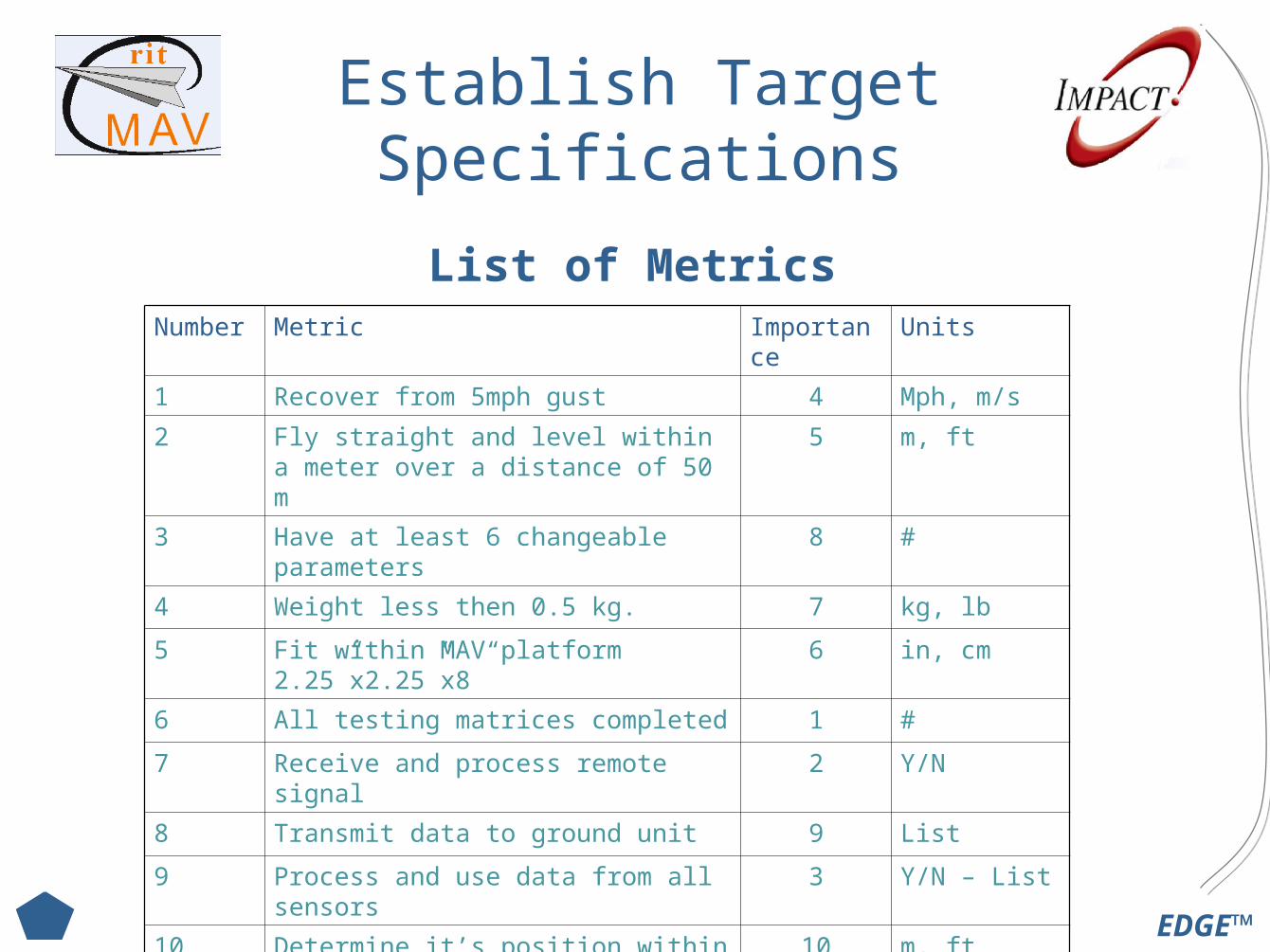
Establish Target Specifications
List of MetricsNumber Metric Importance Units
1 Recover from 5mph gust 4 Mph, m/s
2 Fly straight and level within a meter over a distance of 50 m
5 m, ft
3 Have at least 6 changeable parameters 8 #
4 Weight less then 0.5 kg. 7 kg, lb
5 Fit within MAV platform 2.25”x2.25”x8” 6 in, cm
6 All testing matrices completed 1 #
7 Receive and process remote signal 2 Y/N
8 Transmit data to ground unit 9 List
9 Process and use data from all sensors 3 Y/N – List
10 Determine it’s position within 1 meter 10 m, ft
11 Fly a designated pattern within 2 meters 11 m, ft

EDGE™
Concept Development
EDGE™
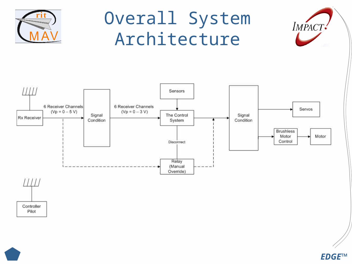
Overall System Architecture
EDGE™
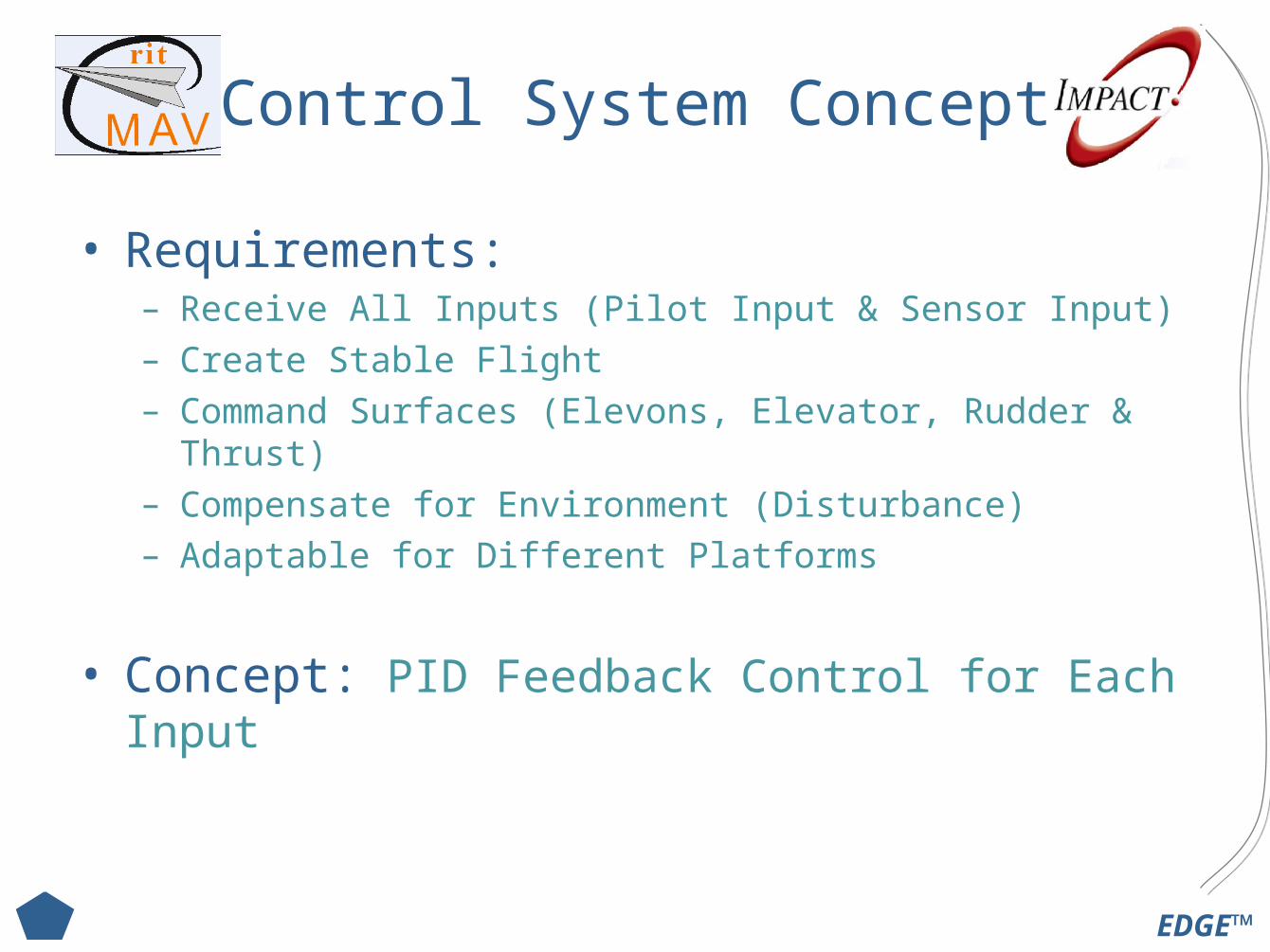
Control System Concept
• Requirements:– Receive All Inputs (Pilot Input & Sensor Input)– Create Stable Flight– Command Surfaces (Elevons, Elevator, Rudder & Thrust)– Compensate for Environment (Disturbance)– Adaptable for Different Platforms
• Concept: PID Feedback Control for Each Input
EDGE™
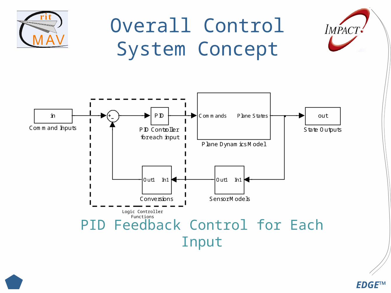
Overall Control System Concept
PID Feedback Control for Each Input
out
State Outputs
In1Out1
Sensor Models
Commands Plane States
Plane Dynamics Model
PID
PID Controller for each input
In1Out1
Conversions
in
Command Inputs
Logic Controller Functions
EDGE™
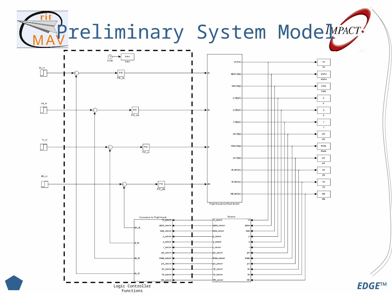
Preliminary System Model
Logic Controller Functions
EDGE™
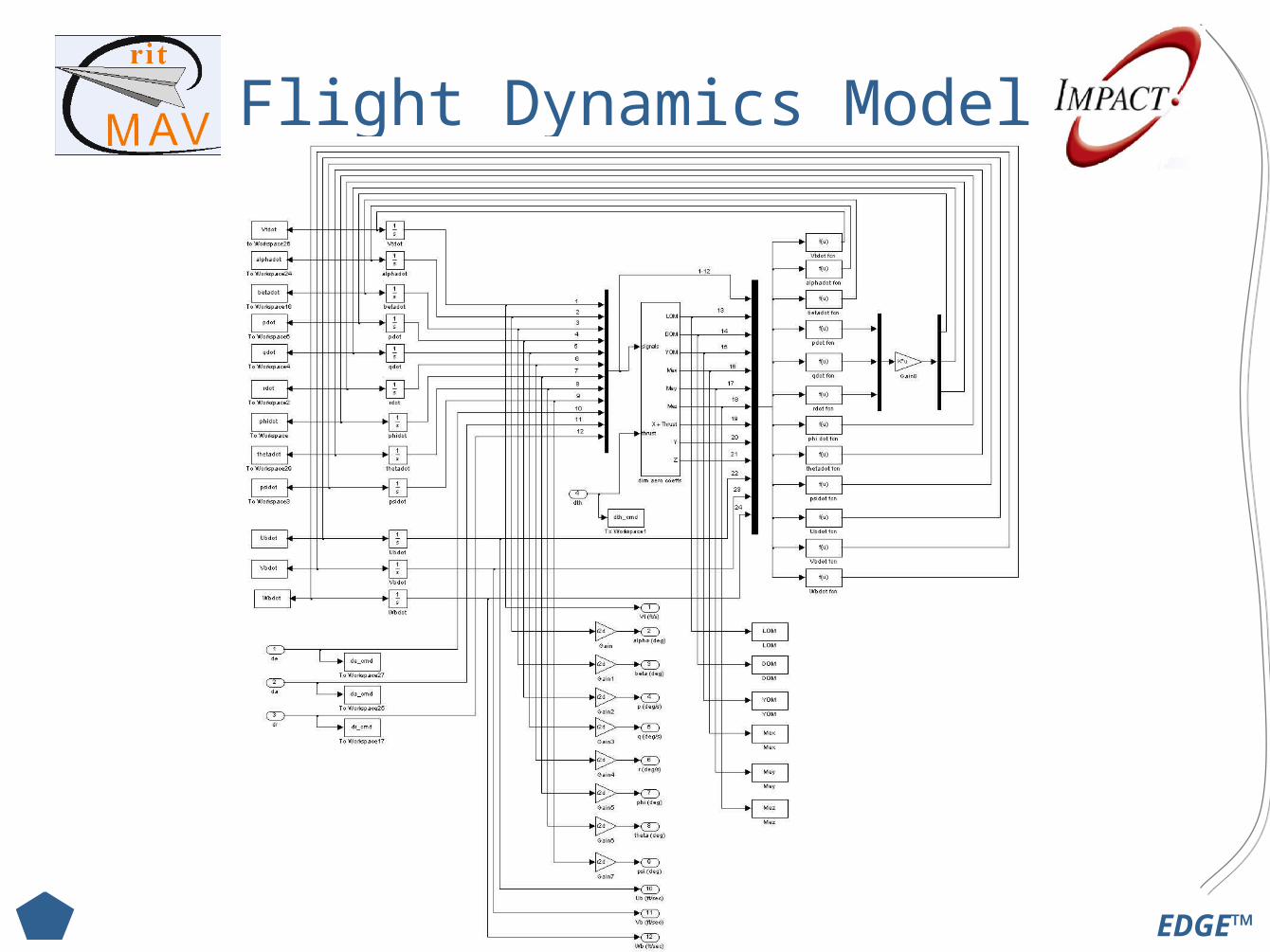
Flight Dynamics Model

EDGE™
Logic Controller
• Selection Criteria– Control Capability
– Adaptability– Inputs Receivable– Weight & Size– Cost– Complexity– Time to get working

EDGE™
Logic Controller
• Concepts– Last Year’s O-Navi Controller– Purchase different commercial fully developed board– Design and build from parts
O-Navi Microcontroller
EDGE™
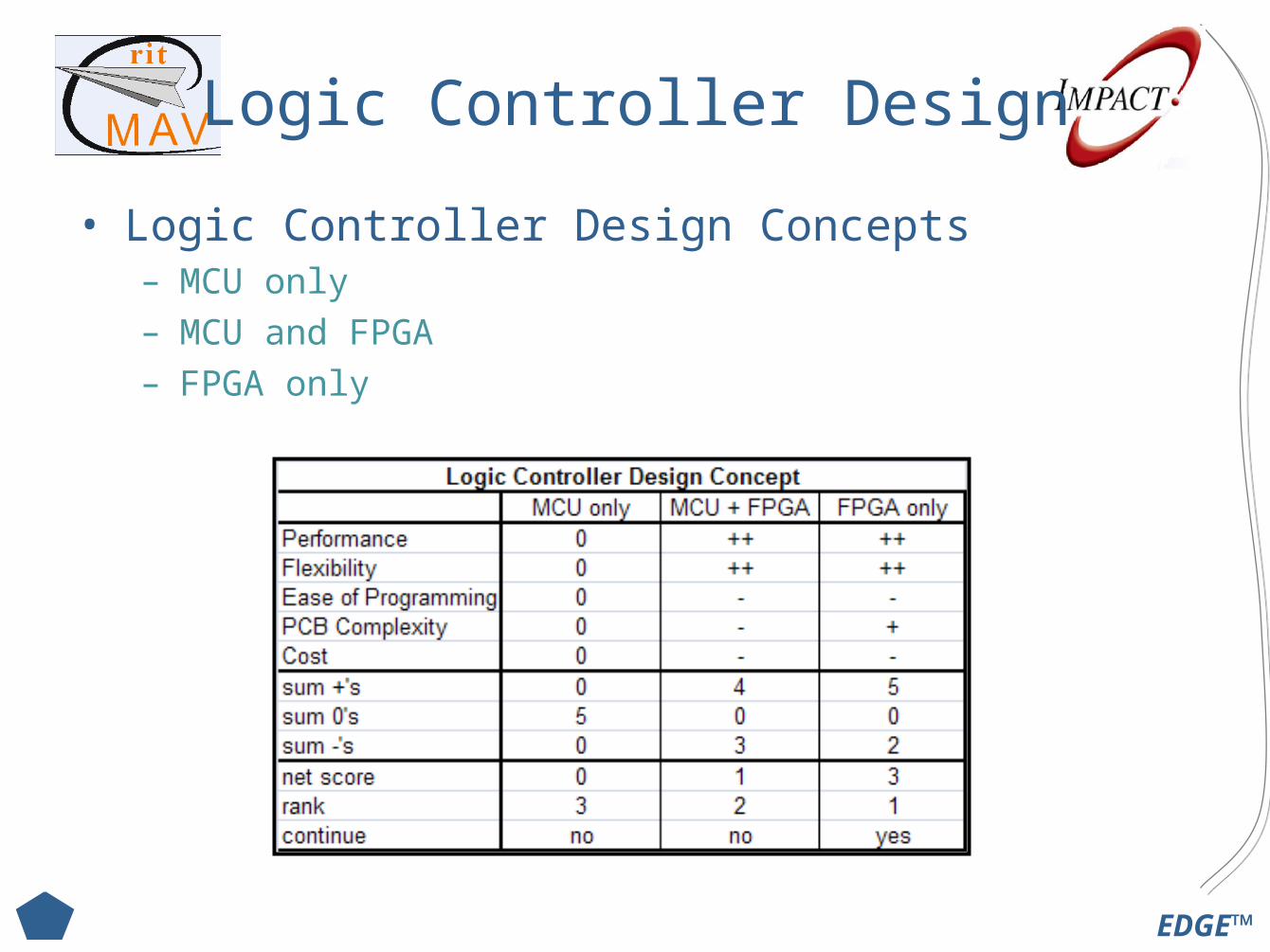
Logic Controller Design
• Logic Controller Design Concepts– MCU only– MCU and FPGA– FPGA only
EDGE™
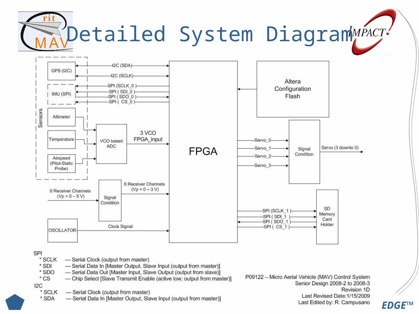
Detailed System Diagram
EDGE™
FPGA Selection
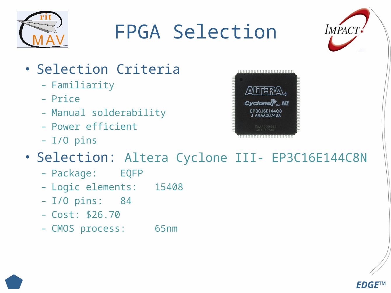
• Selection Criteria– Familiarity– Price– Manual solderability– Power efficient– I/O pins
• Selection: Altera Cyclone III- EP3C16E144C8N– Package: EQFP– Logic elements: 15408– I/O pins: 84– Cost: $26.70 – CMOS process: 65nm
EDGE™
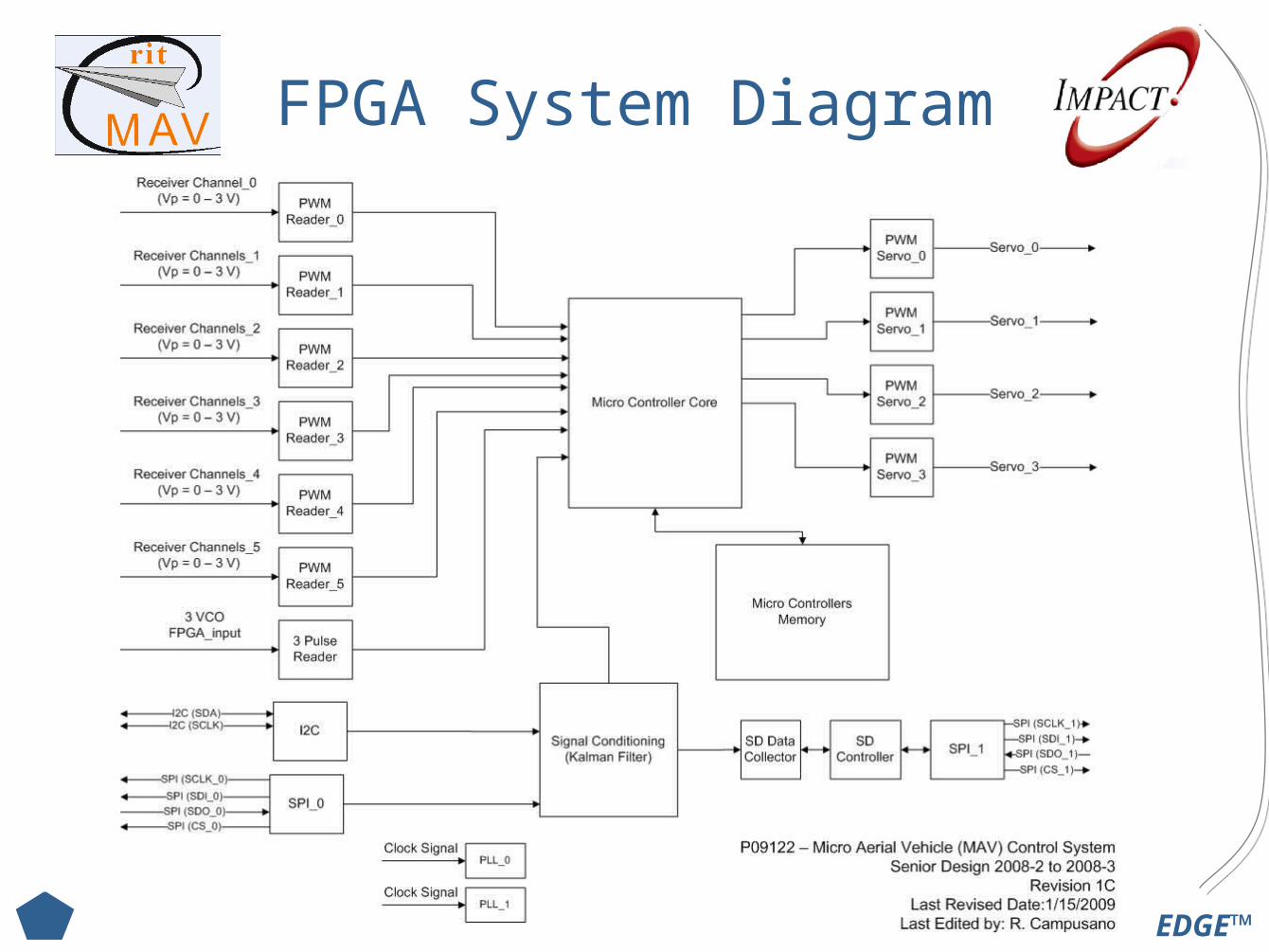
FPGA System Diagram
EDGE™
Sensor Concepts
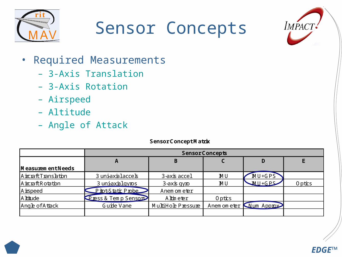
• Required Measurements– 3-Axis Translation
– 3-Axis Rotation
– Airspeed
– Altitude
– Angle of Attack
Sensor Concept Matrix
Measurement NeedsAircraft Translation 3 uni-axial accels 3-axis accel IMU IMU+GPSAircraft Rotation 3 uni-axial gyros 3-axis gyro IMU IMU+GPS OpticsAirspeed Pitot-Static Probe AnemometerAltitude Press & Temp Sensors Altimeter OpticsAngle of Attack Guide Vane Multi Hole Pressure Anemometer Num Approx
Sensor ConceptsC B A D E
EDGE™
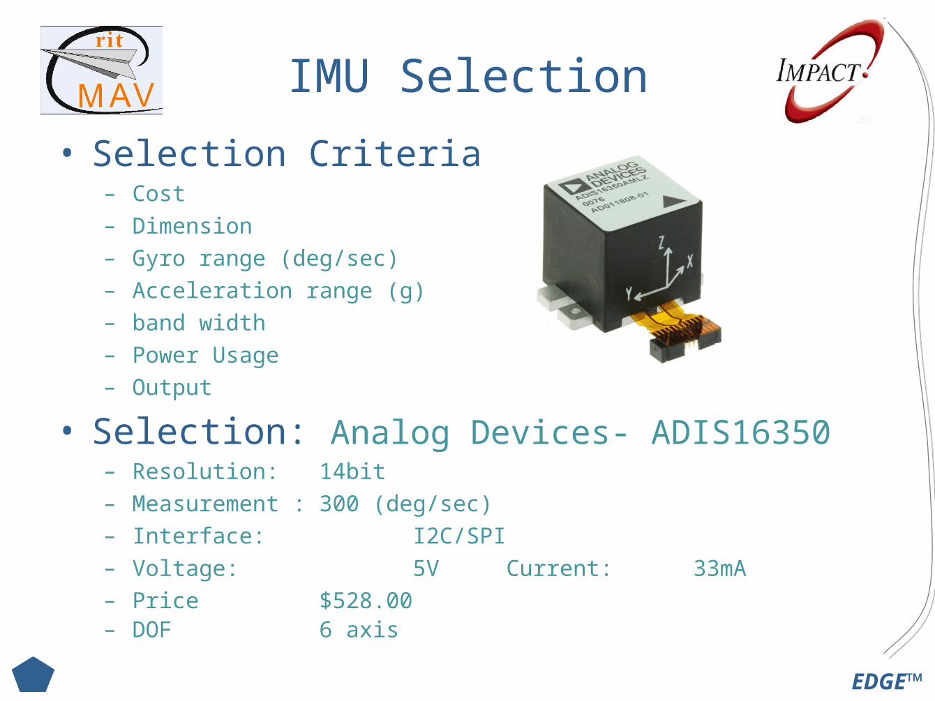
IMU Selection
• Selection Criteria– Cost– Dimension– Gyro range (deg/sec)– Acceleration range (g)– band width– Power Usage– Output
• Selection: Analog Devices- ADIS16350– Resolution: 14bit– Measurement : 300 (deg/sec)– Interface: I2C/SPI– Voltage: 5V Current: 33mA– Price $528.00– DOF 6 axis
EDGE™
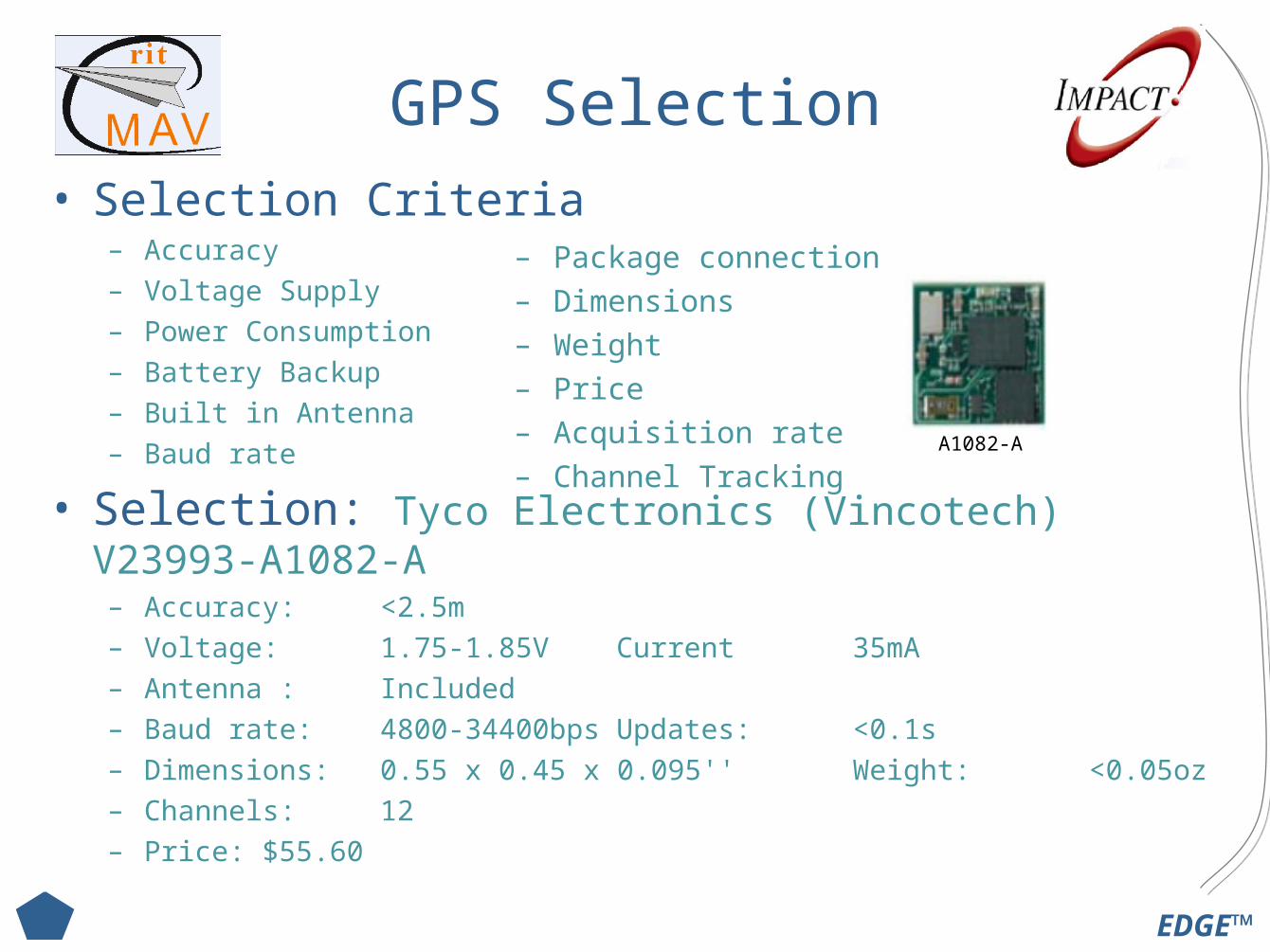
GPS Selection
• Selection Criteria– Accuracy– Voltage Supply– Power Consumption– Battery Backup – Built in Antenna– Baud rate
• Selection: Tyco Electronics (Vincotech) V23993-A1082-A– Accuracy: <2.5m – Voltage: 1.75-1.85V Current 35mA– Antenna : Included – Baud rate: 4800-34400bps Updates: <0.1s – Dimensions: 0.55 x 0.45 x 0.095'' Weight: <0.05oz – Channels: 12– Price: $55.60
– Package connection– Dimensions – Weight – Price – Acquisition rate – Channel Tracking
A1082-A
EDGE™
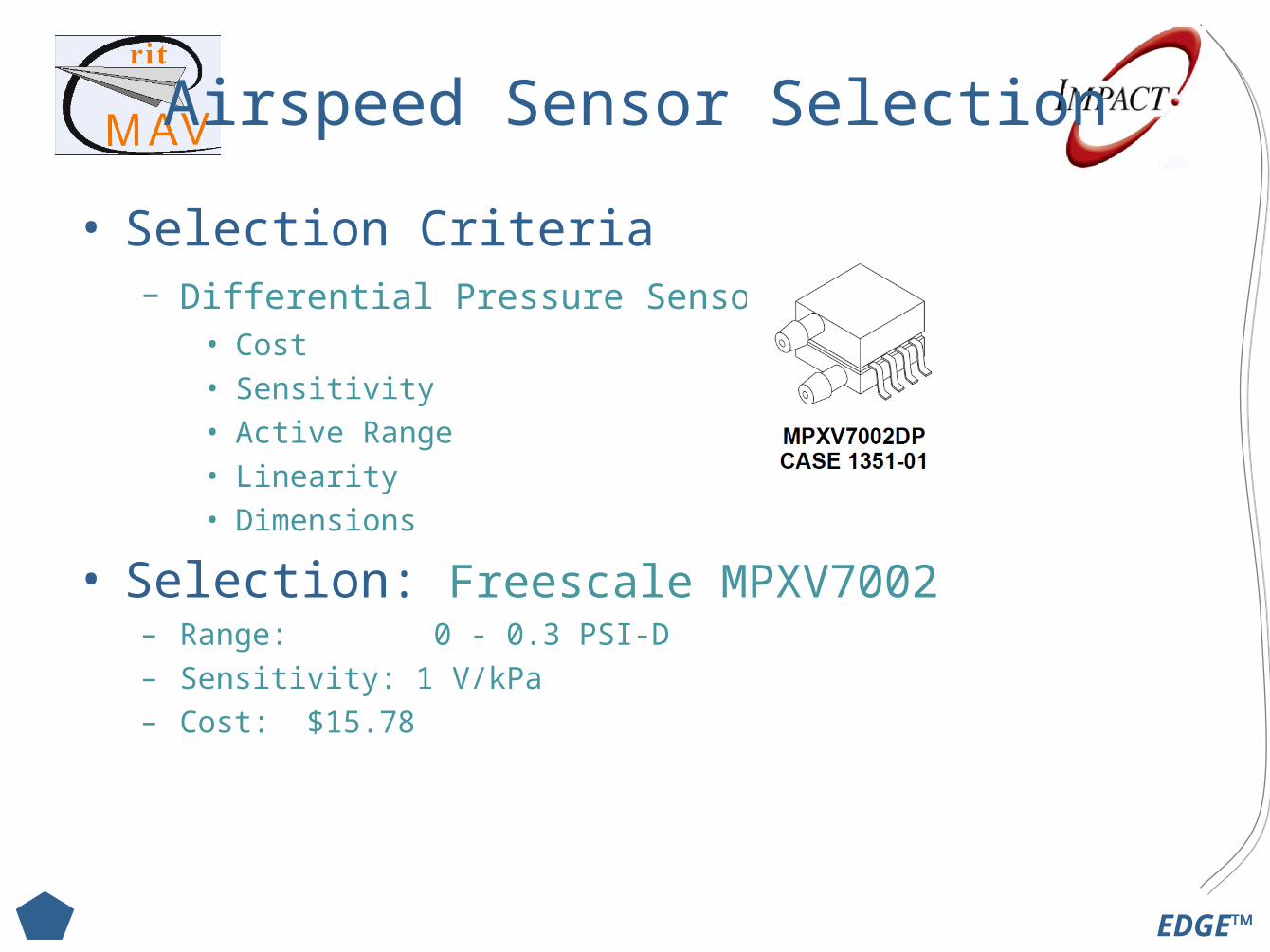
Airspeed Sensor Selection
• Selection Criteria– Differential Pressure Sensor:
• Cost • Sensitivity • Active Range• Linearity • Dimensions
• Selection: Freescale MPXV7002– Range: 0 - 0.3 PSI-D– Sensitivity: 1 V/kPa– Cost: $15.78
EDGE™
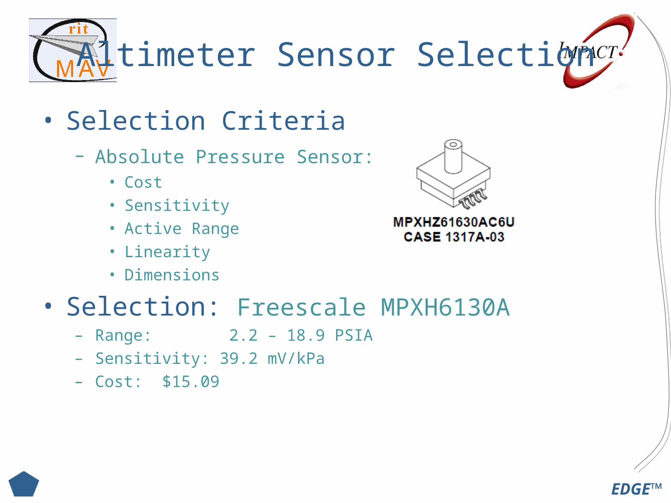
Altimeter Sensor Selection
• Selection Criteria– Absolute Pressure Sensor:
• Cost • Sensitivity • Active Range• Linearity • Dimensions
• Selection: Freescale MPXH6130A– Range: 2.2 – 18.9 PSIA– Sensitivity: 39.2 mV/kPa– Cost: $15.09
EDGE™
Airspeed Sensor Selection
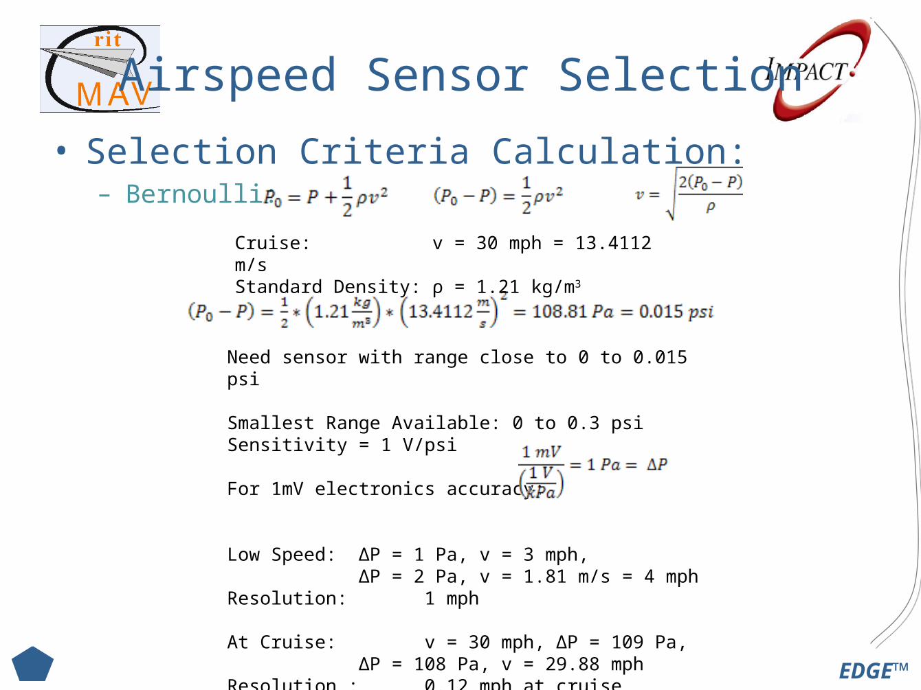
• Selection Criteria Calculation:– Bernoulli:
Need sensor with range close to 0 to 0.015 psi
Smallest Range Available: 0 to 0.3 psiSensitivity = 1 V/psi
For 1mV electronics accuracy:
Low Speed: ΔP = 1 Pa, v = 3 mph, ΔP = 2 Pa, v = 1.81 m/s = 4 mph
Resolution: 1 mph
At Cruise: v = 30 mph, ΔP = 109 Pa, ΔP = 108 Pa, v = 29.88 mph
Resolution : 0.12 mph at cruise
Cruise: v = 30 mph = 13.4112 m/sStandard Density: ρ = 1.21 kg/m3
EDGE™
Altimeter Sensor Selection
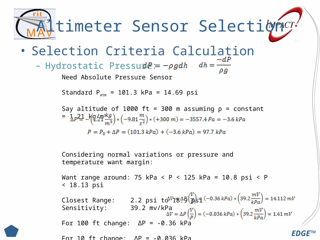
• Selection Criteria Calculation– Hydrostatic Pressure:
Need Absolute Pressure Sensor
Standard Patm = 101.3 kPa = 14.69 psi
Say altitude of 1000 ft = 300 m assuming ρ = constant = 1.21 kg/m3
Considering normal variations or pressure and temperature want margin:
Want range around: 75 kPa < P < 125 kPa = 10.8 psi < P < 18.13 psi
Closest Range: 2.2 psi to 18.9 psiSensitivity: 39.2 mv/kPa
For 100 ft change: ΔP = -0.36 kPa
For 10 ft change: ΔP = -0.036 kPa
For 1 mV change: Δh = 7 ft
EDGE™
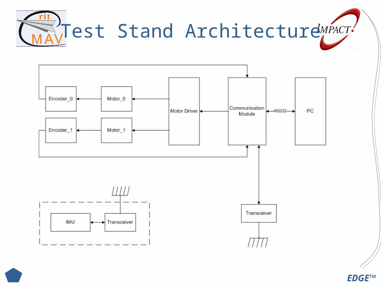
Test Stand Architecture
EDGE™
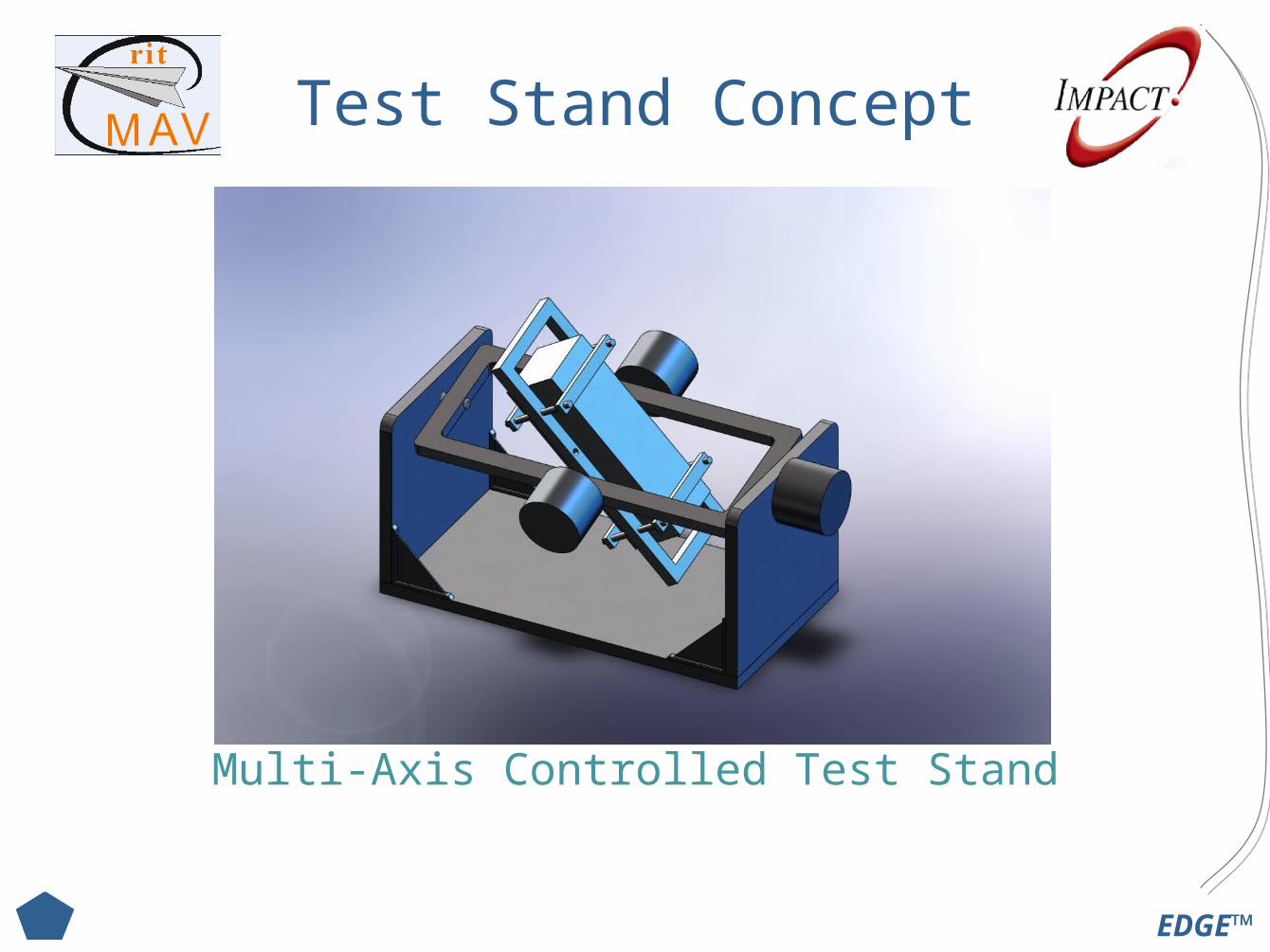
Test Stand Concept
Multi-Axis Controlled Test Stand
EDGE™
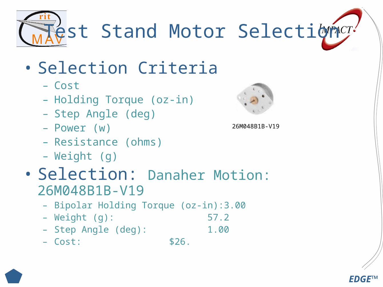
Test Stand Motor Selection
• Selection Criteria– Cost– Holding Torque (oz-in)– Step Angle (deg)– Power (w)– Resistance (ohms)– Weight (g)
• Selection: Danaher Motion: 26M048B1B-V19– Bipolar Holding Torque (oz-in):3.00– Weight (g): 57.2– Step Angle (deg): 1.00– Cost: $26.
26M048B1B-V19

EDGE™
Test Stand Motor Selection
• Selection Criteria Calculation– Torque
Inner Motor: I = 17 lbmin2 (from CAD Model)
Outer Motor: I = 150 lbmin2
Need to calculate max α we want for the test stand
Say max roll rate = 10 rpm (F-18 = 120 rpm)If reaches roll rate by 45 deg (1/8 rev) with constant α
Using Rotational Kinematics: Solving for α:
Calculating Torque:

EDGE™
MSD I Future Work
EDGE™
Control System
• Review & Finalize Non-Linear Plant Model
• Finish Feedback Conversions
• Model Sensors
• Linearize Plant and Sensor Models
• Develop Continuous Control Gains
• Discretize System Model
• Develop Discrete Control Gains
• Generate Control Law Code
EDGE™
Logic Controller
• Review Component Documentation
• Familiarize with NIOS II–Instantiate NIOS II core on FPGA–Store program code in Flash
• Implement Serial Protocols
• Investigate SD Card Data Storage Potential
• Begin Prototyping All Component Communication
EDGE™
Sensors
• Temperature Sensor Selection
• Determine Pitot-Tube Hardware and Location
• Review Sensor Documentation
• Develop Sensor Power Strategy
• Research Sensor Modeling Theory
• Develop PCB layout software knowledge
• Research Method for Digitizing Analog Sensors
EDGE™
Test Stand
• Research & Select Motor Drivers
• Research & Select Encoders
• Select Power Supply
• Select Transceiver Module
• Develop Communication Module
• Develop User Interface
• Refine Test Stand Design–Structure–Wire Routing
EDGE™
Other
• Develop Power Budget– Primary and Secondary Systems– Test Stand
• IMU Stage• Motors
EDGE™
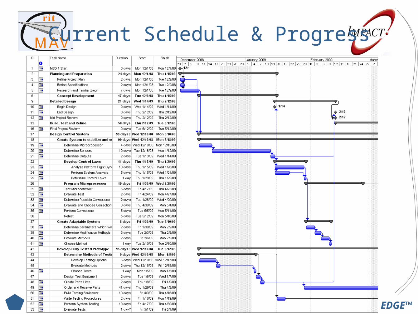
Current Schedule & Progress
EDGE™
MSD I Projected Progress
• Complete Tasks Listed in Future Work
• Finish Detail Design Early– Start Ordering Sensors and Components Early
• EE’s Can Start Modeling Sensors• CE’s Can Start Checking Communication
EDGE™
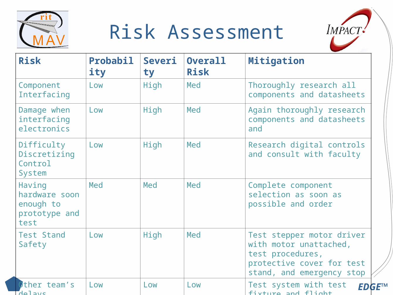
Risk AssessmentRisk Probability Severity Overall Risk Mitigation
Component Interfacing
Low High Med Thoroughly research all components and datasheets
Damage when interfacing electronics
Low High Med Again thoroughly research components and datasheets and
Difficulty Discretizing Control System
Low High Med Research digital controls and consult with faculty
Having hardware soon enough to prototype and test
Med Med Med Complete component selection as soon as possible and order
Test Stand Safety Low High Med Test stepper motor driver with motor unattached, test procedures, protective cover for test stand, and emergency stop
Other team’s delays prevent integration
Low Low Low Test system with test fixture and flight testing with either OTS kit plane or previous year’s MAV platform.