eddy current method for thickness assessment of carburized layers
TRANSCRIPT
Eddy Current method for thickness assessment of carburized layers
Dominik Kukla, Paweł Grzywna, Mateusz Kopeć, Zbigniew Kowalewski
Institute of Fundamental Technological Research, Polish Academy of Sciences
Corresponding author: Dominik Kukla [email protected]
Materials and semi-manufactured products for aviation equipment are usually subjected to increasingly rigorous demands for the quality control. In many cases, like
hardened or carburized wheels or rollers assembled in the gear motors, the control procedures enforce necessity of the selective testing of details coming from
production lines using destructive techniques. The main aim of diagnostic investigations carrying out on series of final products is to assess qualitatively and quantitatively the layers obtained due to carburizing and induction hardening. Unfortunately, such processes increase the fabrication costs significantly, especially
in the case of complex manufacturing technology applied and small-lot production as well. In order to reduce them the attempts for application of non-destructive
testing methods are taken for evaluation of either the layers quality or the products subjected to surface treatments. This paper presents the eddy currents method used for the thickness evaluation of the carburized and induction-hardened layers on the basis of the impedance signal variation. The signal was obtained as a result
of the so-called ‘lift off’ effect. A methodology for the quantitative thickness evaluation of the carburized and induction-hardened layers has been elaborated under
a range of technological parameters. The measurements ranges were defined in the framework of which an identification of the hardened layer was possible using the commercial defectoscope and reference specimens of the fixed thickness. Tests were carried out on specimens made of the ASM6414 steel and subjected
subsequently to carburization and induction hardening. The impedance parameters were measured for selected values of frequency. The results were verified on the
basis of metallographic investigations as well as the microhardness measurements captured in the form of profiles taken from specimens’ cross-sections of different layer thickness.
Keywords: eddy current, hardening, carburizing, layers, non-destructive technique
1. INTRODUCTION
Eddy Current (EC) method is commonly used in defectoscopy
for identification of the surface and subsurface defects [1]. It is
also treated as one of the most popular nondestructive techniques
used in power engineering and aviation diagnostics for the
conductive materials. Nowadays EC method is especially
promising in the studies of material properties, measurements of
coatings thickness and stress assessments. Moreover, the
method is suitable for qualitative and quantitative assessments of
diffusive layers obtained due to carburizing and induction
hardening [2,3]. This paper presents the results of thickness
evaluation of the layers covered on Cr-Ni-Mo steel, using the
‘lift off’ effect. It arises due to changes in the phase angle of the
signal [4]. A methodology for the quantitative thickness
evaluation of the carburized and induction-hardened layers made
on AMS6461 steel specimens has been elaborated under a range
of technological parameters. The results of nondestructive
measurements were verified on the basis of metallographic
investigations as well as the microhardness measurements
captured in the form of profiles taken from specimens’ cross-
sections with fixed layer thickness.
Thickness control of the hardened layer is carried out on the
selected elements coming from manufacturing lines. Up to 25%
of such elements may suffer on some damages, what as a
consequence, increases the fabrication costs significantly.
Development of measurement procedures for the non-destructive
inspection of the hardened components layers thickness enables
a reduction of these costs on one hand, and an acceleration of the
quality control process on the other.
2. EXPERIMENTAL PROCEDURE
Investigations of the hardened layers were carried out on
specimens made of the structural toughening AMS6414 steel
(40HNMA steel – notation according to Polish Standards).
AMS6414 steel is usually used for the production of connecting
rods, steering parts, hub propellers and gear motors. Eddy current
method is the comparative technique, and therefore, it requires a
preparation of a set of reference specimens with fixed layer
thickness in order to calibrate signal properly. The shafts made
of AMS6414 steel were subjected to surface treatment with
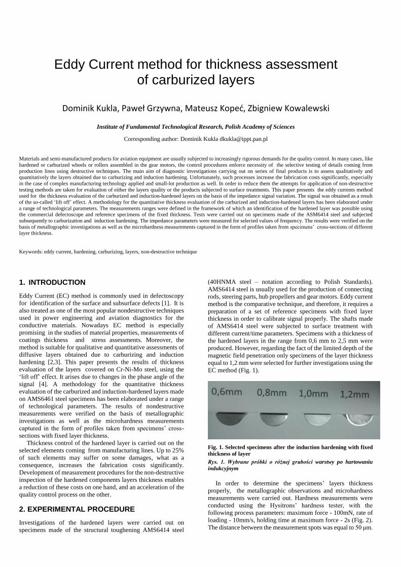
different current/time parameters. Specimens with a thickness of
the hardened layers in the range from 0,6 mm to 2,5 mm were
produced. However, regarding the fact of the limited depth of the
magnetic field penetration only specimens of the layer thickness
equal to 1,2 mm were selected for further investigations using the
EC method (Fig. 1).
Fig. 1. Selected specimens after the induction hardening with fixed
thickness of layer
Rys. 1. Wybrane próbki o różnej grubości warstwy po hartowaniu
indukcyjnym
In order to determine the specimens’ layers thickness properly, the metallographic observations and microhardness
measurements were carried out. Hardness measurements were
conducted using the Hysitrons’ hardness tester, with the
following process parameters: maximum force - 100mN, rate of
loading - 10mm/s, holding time at maximum force - 2s (Fig. 2).
The distance between the measurement spots was equal to 50 μm.
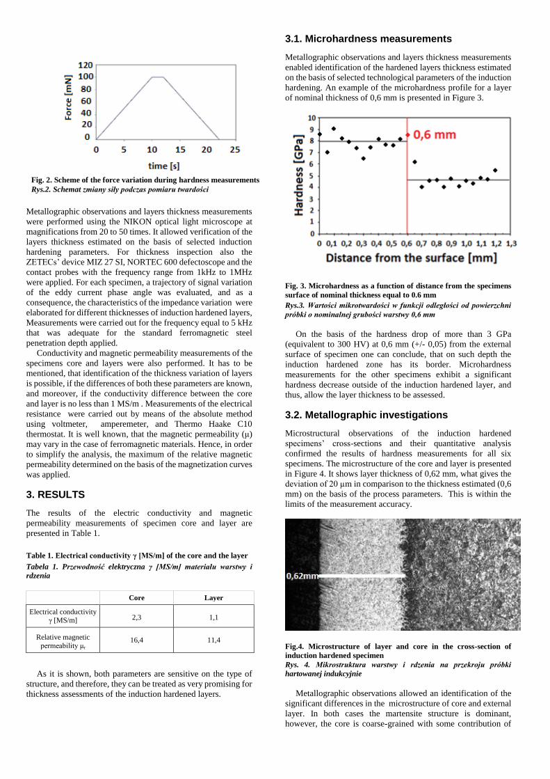
Fig. 2. Scheme of the force variation during hardness measurements
Rys.2. Schemat zmiany siły podczas pomiaru twardości
Metallographic observations and layers thickness measurements
were performed using the NIKON optical light microscope at
magnifications from 20 to 50 times. It allowed verification of the
layers thickness estimated on the basis of selected induction
hardening parameters. For thickness inspection also the
ZETECs’ device MIZ 27 SI, NORTEC 600 defectoscope and the
contact probes with the frequency range from 1kHz to 1MHz
were applied. For each specimen, a trajectory of signal variation
of the eddy current phase angle was evaluated, and as a
consequence, the characteristics of the impedance variation were
elaborated for different thicknesses of induction hardened layers,
Measurements were carried out for the frequency equal to 5 kHz
that was adequate for the standard ferromagnetic steel
penetration depth applied.
Conductivity and magnetic permeability measurements of the
specimens core and layers were also performed. It has to be
mentioned, that identification of the thickness variation of layers
is possible, if the differences of both these parameters are known,
and moreover, if the conductivity difference between the core
and layer is no less than 1 MS/m . Measurements of the electrical
resistance were carried out by means of the absolute method
using voltmeter, amperemeter, and Thermo Haake C10
thermostat. It is well known, that the magnetic permeability (μ)
may vary in the case of ferromagnetic materials. Hence, in order
to simplify the analysis, the maximum of the relative magnetic
permeability determined on the basis of the magnetization curves
was applied.
3. RESULTS
The results of the electric conductivity and magnetic
permeability measurements of specimen core and layer are
presented in Table 1.
Table 1. Electrical conductivity γ [MS/m] of the core and the layer
Tabela 1. Przewodność elektryczna γ [MS/m] materiału warstwy i
rdzenia
Core Layer
Electrical conductivity γ [MS/m] 2,3 1,1
Relative magnetic
permeability μr 16,4 11,4
As it is shown, both parameters are sensitive on the type of
structure, and therefore, they can be treated as very promising for
thickness assessments of the induction hardened layers.
3.1. Microhardness measurements
Metallographic observations and layers thickness measurements
enabled identification of the hardened layers thickness estimated
on the basis of selected technological parameters of the induction
hardening. An example of the microhardness profile for a layer
of nominal thickness of 0,6 mm is presented in Figure 3.
Fig. 3. Microhardness as a function of distance from the specimens
surface of nominal thickness equal to 0.6 mm
Rys.3. Wartości mikrotwardości w funkcji odległości od powierzchni
próbki o nominalnej grubości warstwy 0,6 mm
On the basis of the hardness drop of more than 3 GPa
(equivalent to 300 HV) at 0,6 mm (+/- 0,05) from the external
surface of specimen one can conclude, that on such depth the
induction hardened zone has its border. Microhardness
measurements for the other specimens exhibit a significant
hardness decrease outside of the induction hardened layer, and
thus, allow the layer thickness to be assessed.
3.2. Metallographic investigations
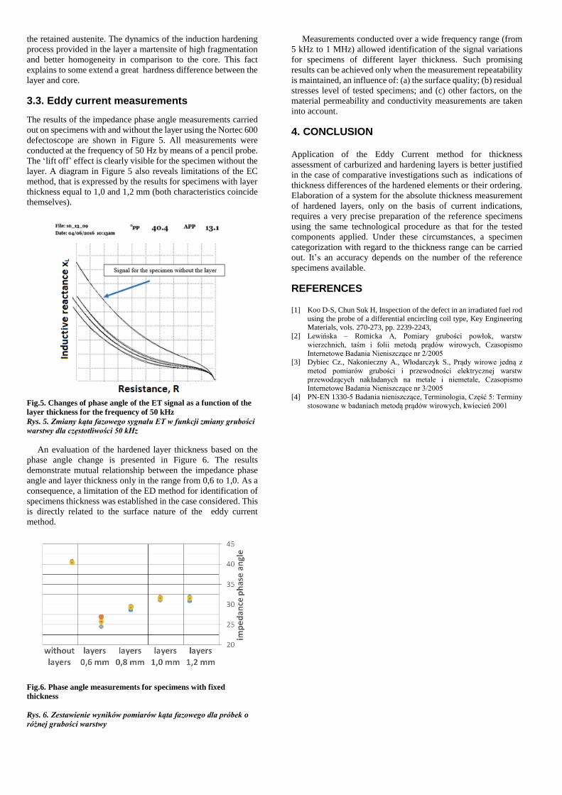
Microstructural observations of the induction hardened
specimens’ cross-sections and their quantitative analysis
confirmed the results of hardness measurements for all six
specimens. The microstructure of the core and layer is presented
in Figure 4. It shows layer thickness of 0,62 mm, what gives the
deviation of 20 µm in comparison to the thickness estimated (0,6
mm) on the basis of the process parameters. This is within the
limits of the measurement accuracy.
Fig.4. Microstructure of layer and core in the cross-section of
induction hardened specimen
Rys. 4. Mikrostruktura warstwy i rdzenia na przekroju próbki
hartowanej indukcyjnie
Metallographic observations allowed an identification of the
significant differences in the microstructure of core and external
layer. In both cases the martensite structure is dominant,
however, the core is coarse-grained with some contribution of
the retained austenite. The dynamics of the induction hardening
process provided in the layer a martensite of high fragmentation
and better homogeneity in comparison to the core. This fact
explains to some extend a great hardness difference between the
layer and core.
3.3. Eddy current measurements
The results of the impedance phase angle measurements carried
out on specimens with and without the layer using the Nortec 600
defectoscope are shown in Figure 5. All measurements were
conducted at the frequency of 50 Hz by means of a pencil probe.
The ‘lift off’ effect is clearly visible for the specimen without the
layer. A diagram in Figure 5 also reveals limitations of the EC
method, that is expressed by the results for specimens with layer
thickness equal to 1,0 and 1,2 mm (both characteristics coincide
themselves).
Fig.5. Changes of phase angle of the ET signal as a function of the
layer thickness for the frequency of 50 kHz
Rys. 5. Zmiany kąta fazowego sygnału ET w funkcji zmiany grubości
warstwy dla częstotliwości 50 kHz
An evaluation of the hardened layer thickness based on the
phase angle change is presented in Figure 6. The results
demonstrate mutual relationship between the impedance phase
angle and layer thickness only in the range from 0,6 to 1,0. As a
consequence, a limitation of the ED method for identification of
specimens thickness was established in the case considered. This
is directly related to the surface nature of the eddy current
method.
Fig.6. Phase angle measurements for specimens with fixed
thickness
Rys. 6. Zestawienie wyników pomiarów kąta fazowego dla próbek o
różnej grubości warstwy
Measurements conducted over a wide frequency range (from
5 kHz to 1 MHz) allowed identification of the signal variations
for specimens of different layer thickness. Such promising
results can be achieved only when the measurement repeatability
is maintained, an influence of: (a) the surface quality; (b) residual
stresses level of tested specimens; and (c) other factors, on the
material permeability and conductivity measurements are taken
into account.
4. CONCLUSION
Application of the Eddy Current method for thickness
assessment of carburized and hardening layers is better justified
in the case of comparative investigations such as indications of
thickness differences of the hardened elements or their ordering.
Elaboration of a system for the absolute thickness measurement
of hardened layers, only on the basis of current indications,
requires a very precise preparation of the reference specimens
using the same technological procedure as that for the tested
components applied. Under these circumstances, a specimen
categorization with regard to the thickness range can be carried
out. It’s an accuracy depends on the number of the reference
specimens available.
REFERENCES
[1] Koo D-S, Chun Suk H, Inspection of the defect in an irradiated fuel rod
using the probe of a differential encircling coil type, Key Engineering
Materials, vols. 270-273, pp. 2239-2243, [2] Lewińska – Romicka A, Pomiary grubości powłok, warstw
wierzchnich, taśm i folii metodą prądów wirowych, Czasopismo
Internetowe Badania Nieniszczące nr 2/2005 [3] Dybiec Cz., Nakonieczny A., Włodarczyk S., Prądy wirowe jedną z
metod pomiarów grubości i przewodności elektrycznej warstw
przewodzących nakładanych na metale i niemetale, Czasopismo Internetowe Badania Nieniszczące nr 3/2005
[4] PN-EN 1330-5 Badania nieniszczące, Terminologia, Część 5: Terminy
stosowane w badaniach metodą prądów wirowych, kwiecień 2001