ed herba class lecture
DESCRIPTION
FEM tutorialsTRANSCRIPT

Fatigue and Damage Tolerance Edward Herba, January 29,2004
Fatigue: Failure mechanism due to cyclic loading.
Damage Tolerance: Fail Safe Design Concept
Fatigue: Failure mechanism due to cyclic loading.
Damage Tolerance: Fail Safe Design Concept

Overview
• Designing for fatigue: Safe Life vs Fail Safe
• Fail-Safe: Fatigue calculation
• Fail-Safe: Damage Tolerance
• Case studies: Crashes involving fatigue
crack propagation
• Fractography
• Summary

Safe-life
• 1952 DeHavilland Comet: World’s first Commercial Jet-liner.
• Designed with Safe-Life concept (tested for life, SF, discarded)
• Assumed no cracks during design lifetime.
• Stress in area of windows was 70% of UTS
• Explosive decompression due to cracking at square window
corners.
• Triggered new design concept: Fail-safe based on fatigue crack
growth, inspection procedures and multiple load paths.

1950’s Comet Aircraft Window

Fail Safe Design Concept
The engineer must :
1) accept all structural members to contain flaws.
2) determine the critical flaw size.
3) use reliable inspection methods and equipment to
monitor flaw size and orientation.
4) assure an appropriate interval between inspections.
5) replace components, parts and members when they
are no longer safe.

Flap track, body & linkages
• Function
• 2nd Load paths (fails-safe, damage tolerant)
• materials (2024 Al, 7075, Ti, Steel)


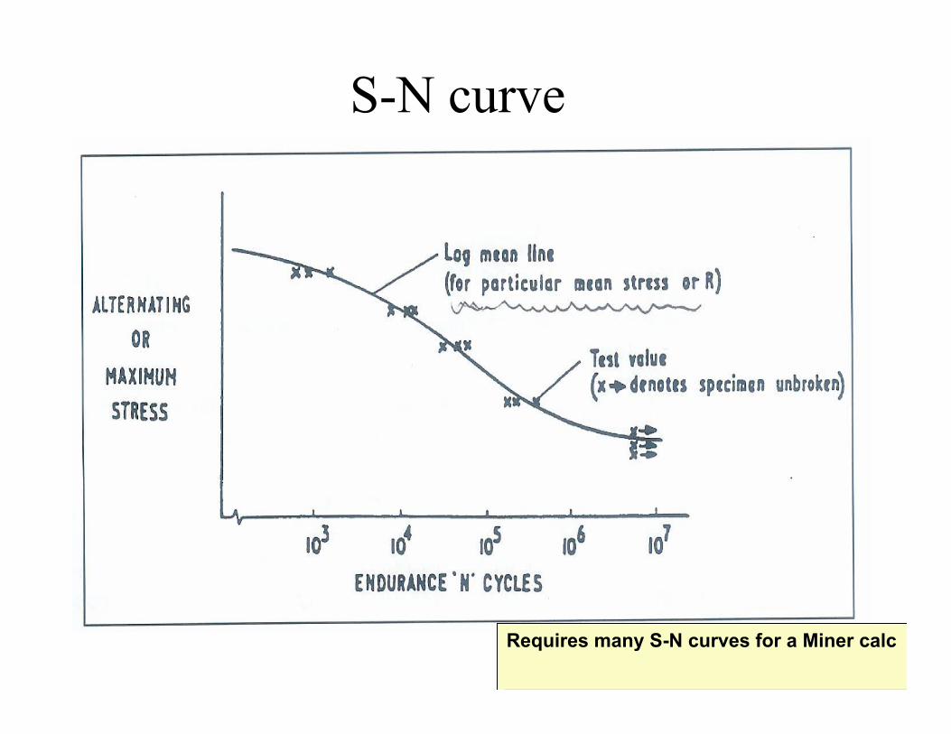
S-N curve
Requires many S-N curves for a Miner calcRequires many S-N curves for a Miner calc

Haigh Diagram for Fatigue Data
R=min/max
Lines of constant endurance
R=min/max
Lines of constant endurance

Cumulative Fatigue Damage
Fatigue damage= n1/N1 after n1 cycles at 1
where N1 is the life at 1 from the S-N curve.
Palmgren-Miner linear cumulative damage hypothesis:
Total Damage caused by a varying amplitude load
cycle is the summation of the damage caused by
each individual loading cycle.
(n1/N1 + n2/N2 + n3/N3 +... ) = 1

Total damage=1/LF
DSG/Fatigue life= 1/LF
Total damage=1/LF
DSG/Fatigue life= 1/LF
Fatigue Calculation
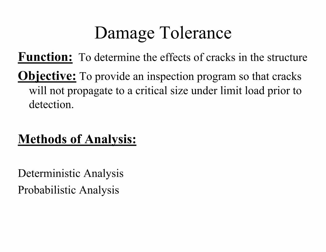
Damage Tolerance
Function: To determine the effects of cracks in the structure
Objective: To provide an inspection program so that cracks
will not propagate to a critical size under limit load prior to
detection.
Methods of Analysis:
Deterministic Analysis
Probabilistic Analysis

Probabilistic vs Deterministic Analysis
Probabilistic Analysis (residual fatigue analysis) is a method
to determine inspection interval when there is a:
• Multiple load path structure (2nd load path not inspectable)
• Insufficient results from fracture mechanics (acrit <adet)
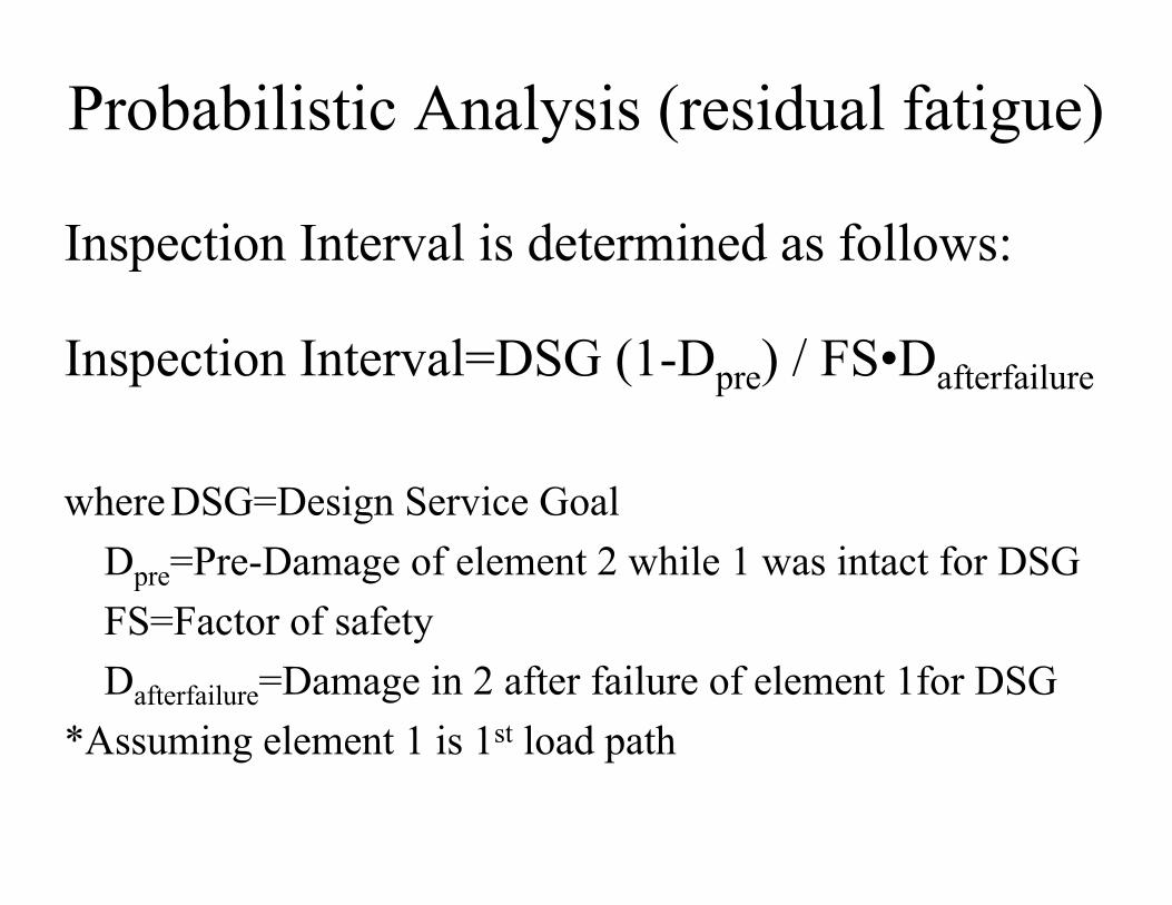
Probabilistic Analysis (residual fatigue)
Inspection Interval is determined as follows:
Inspection Interval=DSG (1-Dpre) / FS•Dafterfailure
where DSG=Design Service Goal
Dpre=Pre-Damage of element 2 while 1 was intact for DSG
FS=Factor of safety
Dafterfailure=Damage in 2 after failure of element 1for DSG
*Assuming element 1 is 1st load path

Deterministic Analysis: Crack Growth
Linear Elastic Fracture Mechanics are used to
determine:
• Crack Growth due to cyclic loads
• Residual strength for a given crack length
• Critical crack length for a given stress level

Fracture Mechanics Assumptions:
• Crack propagation rate depends on K and R for a given
material and conditions.
• Failure occurs when K reaches its critical value (from this
residual strength and acrit can be calculated)

Crack Propagation
a (n) = ai + (da/dn)dn
where
ai = initial crack length (ex: detectable)
da/dn = crack propagation rate (depends on K , R)
n = number of load cycles

Crack Growth
Paris Law: da/dn=A( K)p
Forman Law:
da/dn=Cf ( K)nf
(1-R)Kf- K
Stress Intensity Factor, K
K= • Y • ( • a)
= max- min

Stress Intensity factor: Fracture Toughness, Kcrit
Stress Intensity factor = Stress at crack tip / nominal stress.
Fracture toughness is a material property
Stress Intensity factor = Stress at crack tip / nominal stress.
Fracture toughness is a material property

Critical Crack length & Residual Strength
limit is determined by static stress dept.

Specimen Orientation
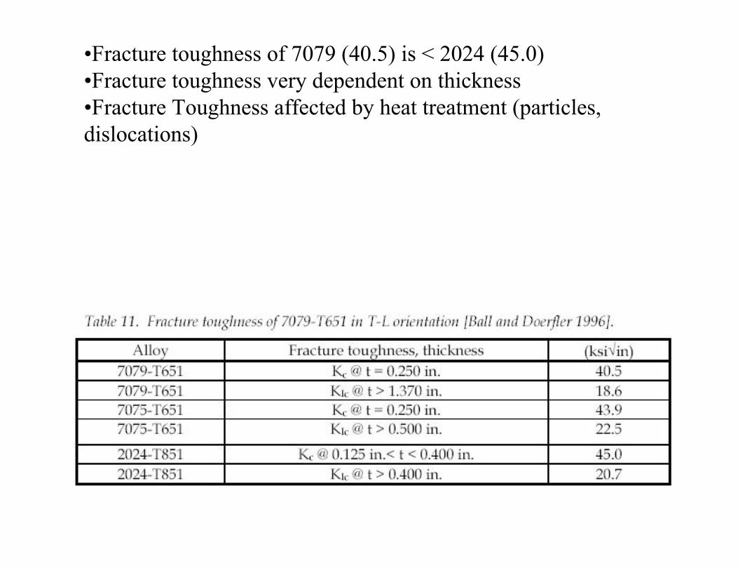
•Fracture toughness of 7079 (40.5) is < 2024 (45.0)
•Fracture toughness very dependent on thickness
•Fracture Toughness affected by heat treatment (particles,
dislocations)

• L-T is worse than
L-S
• Shows crack
propagation rate
is dependent on
grain orientation

Sample Calc: Crack in skin over stringer
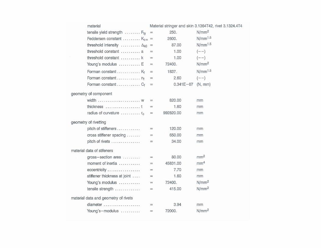

Stress Intensity Correction Function

Progression of Crack Calculation

Locations of MSD on aircraft
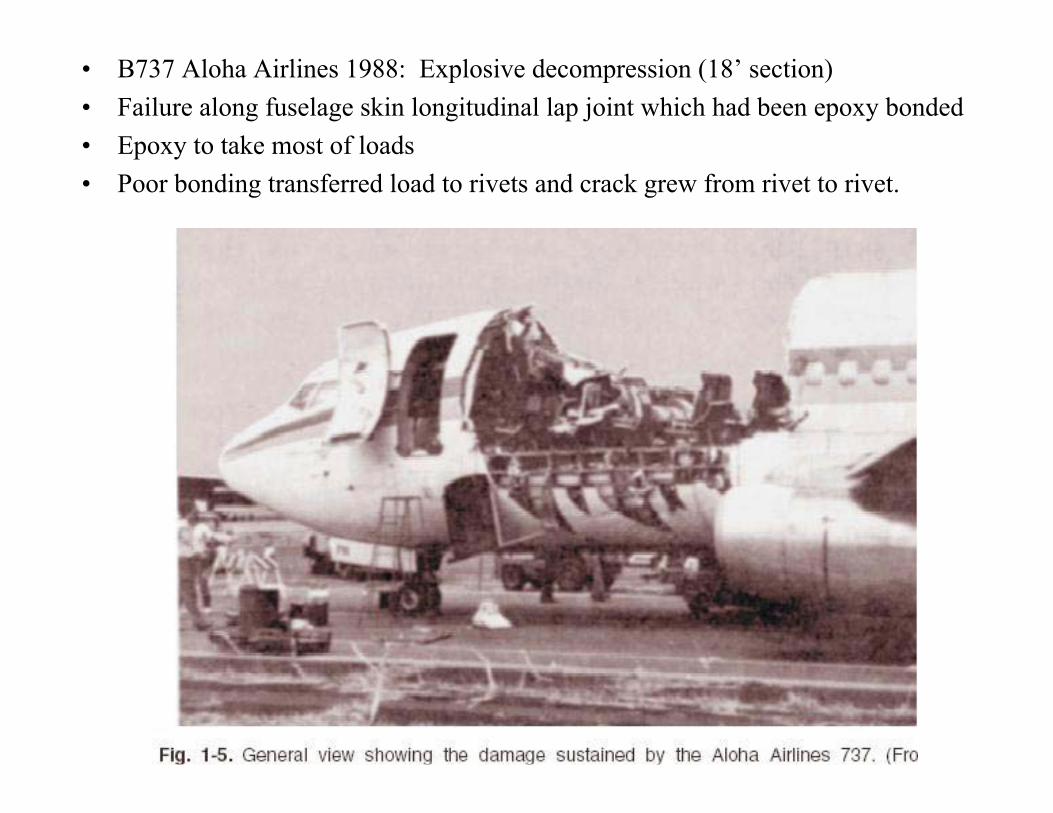
• B737 Aloha Airlines 1988: Explosive decompression (18’ section)
• Failure along fuselage skin longitudinal lap joint which had been epoxy bonded
• Epoxy to take most of loads
• Poor bonding transferred load to rivets and crack grew from rivet to rivet.

Aloha Airlines countersunk rivet where fatigue crack started.

• MSD at Lap joint
• Importance of inspectability (crack was hidden behind a frame)
• Small crack was spotted, joint was disassembled and a much
longer crack found underneath.

•Japan Airlines B747 Crash 1985 (explosive
decompression of fuselage)
•Repaired bulkhead after tail strike was not done
properly.
•Doubler was not continuous putting overload on
the skin.
•Fatigue cracks at rivet holes, then linked (MSD)
and then failure.

Japan Airlines: Bulkhead failure

Chicago DC-10 crash 1979
•Engine fell off during take-off
•Incorrect engine removal procedure caused
fracture to engine support.
•Fatigue crack growth then started at this
cracked upper flange of aft bulkhead.
•The residual strength of the component was
insufficient and complete failure occurred.


Fractography
• SEM showing fatigue striations (1 per cycle in stageII)
• multiple crack origins

Summary
• Fatigue: Miner Rule of linear accumulated
damage
• Damage Tolerance: Crack growth rate is
controlled by K, R
• Importance of surface finish, assembly,
inspectability.