ecss-e-70-41a (30 january 2003) - home - the ccsds ... completed (closed wgs)/pac… · 4.10...
TRANSCRIPT

FOR SPACE STANDARDIZATION
EUROPEAN COOPERATION
ECSS
Space engineering
Ground systems and operations —Telemetry and telecommand packetutilization
ECSS SecretariatESA-ESTEC
Requirements & Standards DivisionNoordwijk, The Netherlands
ECSS-E-70-41A30 January 2003

ECSS30 January 2003ECSS--E--70--41A
2
Published by: ESA Publications DivisionESTEC, P.O. Box 299,2200 AG Noordwijk,The Netherlands
ISSN: 1028-396X
Price: � 30
Printed in The Netherlands
Copyright 2003 E by the European Space Agency for the members of ECSS

ECSS 30 January 2003
ECSS--E--70--41A
3
Foreword
This Standard is one of the series of ECSS Standards intended to be appliedtogether for the management, engineering and product assurance in spaceprojects and applications. ECSS is a cooperative effort of the European SpaceAgency, national space agencies and European industry associations for thepurpose of developing and maintaining common standards.
Requirements in thisStandardare defined in termsofwhat shall be accomplished,rather than in terms of how to organize and perform the necessary work. Thisallows existing organizational structures and methods to be applied where theyare effective, and for the structures and methods to evolve as necessary withoutrewriting the standards.
The formulation of this Standard takes into account the existing ISO 9000 familyof documents.
This Standard has been prepared by the ECSS Working Group for GroundSystems and Operations, reviewed by the ECSSEngineering Panel and approvedby the ECSS Steering Board.

ECSS30 January 2003ECSS--E--70--41A
4
(This page is intentionally left blank)

ECSS 30 January 2003
ECSS--E--70--41A
5
Introduction
ECSS--E--50 and the CCSDS recommendations for packet telemetry andtelecommand address the end-to-end transport of telemetry and telecommanddata between user applications on the ground and application processes on-boardthe satellite, and the intermediate transfer of these data through the differentelements of the ground and space segments.
This packet utilization standard (PUS) complements these standards by definingthe application-level interface between ground and space, in order to satisfy therequirements of electrical integration and testing and flight operations.

ECSS30 January 2003ECSS--E--70--41A
6
(This page is intentionally left blank)

ECSS 30 January 2003
ECSS--E--70--41A
7
Contents
Foreword 3. . . . . . . . . . . . . . . . . . . . . . . . . . . . . . . . . . . . . . . . . . . . . . . . . . . . . . . . . . . . . . . . . . . .
Introduction 5. . . . . . . . . . . . . . . . . . . . . . . . . . . . . . . . . . . . . . . . . . . . . . . . . . . . . . . . . . . . . . . . . .
1 Scope 13. . . . . . . . . . . . . . . . . . . . . . . . . . . . . . . . . . . . . . . . . . . . . . . . . . . . . . . . . . . . . . . . . . .
2 Normative references 15. . . . . . . . . . . . . . . . . . . . . . . . . . . . . . . . . . . . . . . . . . . . . . . . . . . . .
3 Terms, definitions and abbreviated terms 17. . . . . . . . . . . . . . . . . . . . . . . . . . . . . . . . . .3.1 Terms and definitions 17. . . . . . . . . . . . . . . . . . . . . . . . . . . . . . . . . . . . . . . . . . . . . . .3.2 Abbreviated terms 20. . . . . . . . . . . . . . . . . . . . . . . . . . . . . . . . . . . . . . . . . . . . . . . . .
4 PUS operations concepts 23. . . . . . . . . . . . . . . . . . . . . . . . . . . . . . . . . . . . . . . . . . . . . . . . . .4.1 Introduction 23. . . . . . . . . . . . . . . . . . . . . . . . . . . . . . . . . . . . . . . . . . . . . . . . . . . . . . .4.2 Application processes 24. . . . . . . . . . . . . . . . . . . . . . . . . . . . . . . . . . . . . . . . . . . . . .4.3 Packet design and routing 24. . . . . . . . . . . . . . . . . . . . . . . . . . . . . . . . . . . . . . . . . .4.4 Telecommanding 26. . . . . . . . . . . . . . . . . . . . . . . . . . . . . . . . . . . . . . . . . . . . . . . . .4.5 Telemetry reporting 30. . . . . . . . . . . . . . . . . . . . . . . . . . . . . . . . . . . . . . . . . . . . . . . .4.6 Software management 31. . . . . . . . . . . . . . . . . . . . . . . . . . . . . . . . . . . . . . . . . . . . .4.7 On-board operations scheduling 32. . . . . . . . . . . . . . . . . . . . . . . . . . . . . . . . . . . .4.8 On-board monitoring 33. . . . . . . . . . . . . . . . . . . . . . . . . . . . . . . . . . . . . . . . . . . . . .4.9 On-board operations procedures 34. . . . . . . . . . . . . . . . . . . . . . . . . . . . . . . . . . . .4.10 Attaching actions to on-board events 34. . . . . . . . . . . . . . . . . . . . . . . . . . . . . . . .4.11 On-board storage and retrieval 34. . . . . . . . . . . . . . . . . . . . . . . . . . . . . . . . . . . . . .4.12 Telemetry generation and forwarding 35. . . . . . . . . . . . . . . . . . . . . . . . . . . . . . . .4.13 Memory management 35. . . . . . . . . . . . . . . . . . . . . . . . . . . . . . . . . . . . . . . . . . . . .4.14 Diagnostic mode 36. . . . . . . . . . . . . . . . . . . . . . . . . . . . . . . . . . . . . . . . . . . . . . . . . .4.15 Off-line testing 37. . . . . . . . . . . . . . . . . . . . . . . . . . . . . . . . . . . . . . . . . . . . . . . . . . . . .
5 Service specification 39. . . . . . . . . . . . . . . . . . . . . . . . . . . . . . . . . . . . . . . . . . . . . . . . . . . . . .5.1 Introduction 39. . . . . . . . . . . . . . . . . . . . . . . . . . . . . . . . . . . . . . . . . . . . . . . . . . . . . . .5.2 Conventions 40. . . . . . . . . . . . . . . . . . . . . . . . . . . . . . . . . . . . . . . . . . . . . . . . . . . . . .

ECSS30 January 2003ECSS--E--70--41A
8
5.3 Telecommand packet structure 42. . . . . . . . . . . . . . . . . . . . . . . . . . . . . . . . . . . . .5.4 Telemetry source packet structure 46. . . . . . . . . . . . . . . . . . . . . . . . . . . . . . . . . . .5.5 Standard services 50. . . . . . . . . . . . . . . . . . . . . . . . . . . . . . . . . . . . . . . . . . . . . . . . . .
6 Telecommand verification service 51. . . . . . . . . . . . . . . . . . . . . . . . . . . . . . . . . . . . . . . . .6.1 Scope 51. . . . . . . . . . . . . . . . . . . . . . . . . . . . . . . . . . . . . . . . . . . . . . . . . . . . . . . . . . .6.2 Service concept 51. . . . . . . . . . . . . . . . . . . . . . . . . . . . . . . . . . . . . . . . . . . . . . . . . . .6.3 Service requests and reports 52. . . . . . . . . . . . . . . . . . . . . . . . . . . . . . . . . . . . . . . .6.4 Capability sets 55. . . . . . . . . . . . . . . . . . . . . . . . . . . . . . . . . . . . . . . . . . . . . . . . . . . .
7 Device command distribution service 57. . . . . . . . . . . . . . . . . . . . . . . . . . . . . . . . . . . . .7.1 Scope 57. . . . . . . . . . . . . . . . . . . . . . . . . . . . . . . . . . . . . . . . . . . . . . . . . . . . . . . . . . .7.2 Service concept 57. . . . . . . . . . . . . . . . . . . . . . . . . . . . . . . . . . . . . . . . . . . . . . . . . . .7.3 Service requests and reports 58. . . . . . . . . . . . . . . . . . . . . . . . . . . . . . . . . . . . . . . .7.4 Capability sets 59. . . . . . . . . . . . . . . . . . . . . . . . . . . . . . . . . . . . . . . . . . . . . . . . . . . .
8 Housekeeping and diagnostic data reporting service 61. . . . . . . . . . . . . . . . . . . . . .8.1 Scope 61. . . . . . . . . . . . . . . . . . . . . . . . . . . . . . . . . . . . . . . . . . . . . . . . . . . . . . . . . . .8.2 Service concept 61. . . . . . . . . . . . . . . . . . . . . . . . . . . . . . . . . . . . . . . . . . . . . . . . . . .8.3 Service requests and reports 64. . . . . . . . . . . . . . . . . . . . . . . . . . . . . . . . . . . . . . . .8.4 Capability sets 70. . . . . . . . . . . . . . . . . . . . . . . . . . . . . . . . . . . . . . . . . . . . . . . . . . . .
9 Parameter statistics reporting service 73. . . . . . . . . . . . . . . . . . . . . . . . . . . . . . . . . . . . . .9.1 Scope 73. . . . . . . . . . . . . . . . . . . . . . . . . . . . . . . . . . . . . . . . . . . . . . . . . . . . . . . . . . .9.2 Service concept 73. . . . . . . . . . . . . . . . . . . . . . . . . . . . . . . . . . . . . . . . . . . . . . . . . . .9.3 Service requests and reports 74. . . . . . . . . . . . . . . . . . . . . . . . . . . . . . . . . . . . . . . .9.4 Capability sets 77. . . . . . . . . . . . . . . . . . . . . . . . . . . . . . . . . . . . . . . . . . . . . . . . . . . .
10 Event reporting service 79. . . . . . . . . . . . . . . . . . . . . . . . . . . . . . . . . . . . . . . . . . . . . . . . . . .10.1 Scope 79. . . . . . . . . . . . . . . . . . . . . . . . . . . . . . . . . . . . . . . . . . . . . . . . . . . . . . . . . . .10.2 Service concept 79. . . . . . . . . . . . . . . . . . . . . . . . . . . . . . . . . . . . . . . . . . . . . . . . . . .10.3 Service requests and reports 80. . . . . . . . . . . . . . . . . . . . . . . . . . . . . . . . . . . . . . . .10.4 Capability sets 81. . . . . . . . . . . . . . . . . . . . . . . . . . . . . . . . . . . . . . . . . . . . . . . . . . . .
11 Memory management service 83. . . . . . . . . . . . . . . . . . . . . . . . . . . . . . . . . . . . . . . . . . . .11.1 Scope 83. . . . . . . . . . . . . . . . . . . . . . . . . . . . . . . . . . . . . . . . . . . . . . . . . . . . . . . . . . .11.2 Service concept 83. . . . . . . . . . . . . . . . . . . . . . . . . . . . . . . . . . . . . . . . . . . . . . . . . . .11.3 Service requests and reports 84. . . . . . . . . . . . . . . . . . . . . . . . . . . . . . . . . . . . . . . .11.4 Capability sets 89. . . . . . . . . . . . . . . . . . . . . . . . . . . . . . . . . . . . . . . . . . . . . . . . . . . .
12 Function management service 91. . . . . . . . . . . . . . . . . . . . . . . . . . . . . . . . . . . . . . . . . . . .12.1 Scope 91. . . . . . . . . . . . . . . . . . . . . . . . . . . . . . . . . . . . . . . . . . . . . . . . . . . . . . . . . . .12.2 Service concept 91. . . . . . . . . . . . . . . . . . . . . . . . . . . . . . . . . . . . . . . . . . . . . . . . . . .12.3 Service requests and reports 91. . . . . . . . . . . . . . . . . . . . . . . . . . . . . . . . . . . . . . . .12.4 Capability sets 93. . . . . . . . . . . . . . . . . . . . . . . . . . . . . . . . . . . . . . . . . . . . . . . . . . . .
13 Time management service 95. . . . . . . . . . . . . . . . . . . . . . . . . . . . . . . . . . . . . . . . . . . . . . . .13.1 Scope 95. . . . . . . . . . . . . . . . . . . . . . . . . . . . . . . . . . . . . . . . . . . . . . . . . . . . . . . . . . .13.2 Service concept 95. . . . . . . . . . . . . . . . . . . . . . . . . . . . . . . . . . . . . . . . . . . . . . . . . . .13.3 Service requests and reports 96. . . . . . . . . . . . . . . . . . . . . . . . . . . . . . . . . . . . . . . .13.4 Capability sets 97. . . . . . . . . . . . . . . . . . . . . . . . . . . . . . . . . . . . . . . . . . . . . . . . . . . .

ECSS 30 January 2003
ECSS--E--70--41A
9
14 On-board operations scheduling service 99. . . . . . . . . . . . . . . . . . . . . . . . . . . . . . . . . . .14.1 Scope 99. . . . . . . . . . . . . . . . . . . . . . . . . . . . . . . . . . . . . . . . . . . . . . . . . . . . . . . . . . .14.2 Service concept 99. . . . . . . . . . . . . . . . . . . . . . . . . . . . . . . . . . . . . . . . . . . . . . . . . . .14.3 Service requests and reports 103. . . . . . . . . . . . . . . . . . . . . . . . . . . . . . . . . . . . . . . .14.4 Capability sets 116. . . . . . . . . . . . . . . . . . . . . . . . . . . . . . . . . . . . . . . . . . . . . . . . . . . .
15 On-board monitoring service 119. . . . . . . . . . . . . . . . . . . . . . . . . . . . . . . . . . . . . . . . . . . . . .15.1 Scope 119. . . . . . . . . . . . . . . . . . . . . . . . . . . . . . . . . . . . . . . . . . . . . . . . . . . . . . . . . . .15.2 Service concept 119. . . . . . . . . . . . . . . . . . . . . . . . . . . . . . . . . . . . . . . . . . . . . . . . . . .15.3 Service requests and reports 123. . . . . . . . . . . . . . . . . . . . . . . . . . . . . . . . . . . . . . . .15.4 Capability sets 134. . . . . . . . . . . . . . . . . . . . . . . . . . . . . . . . . . . . . . . . . . . . . . . . . . . .
16 Large data transfer service 135. . . . . . . . . . . . . . . . . . . . . . . . . . . . . . . . . . . . . . . . . . . . . . .16.1 Scope 135. . . . . . . . . . . . . . . . . . . . . . . . . . . . . . . . . . . . . . . . . . . . . . . . . . . . . . . . . . .16.2 Service concept 136. . . . . . . . . . . . . . . . . . . . . . . . . . . . . . . . . . . . . . . . . . . . . . . . . . .16.3 Service requests and reports 139. . . . . . . . . . . . . . . . . . . . . . . . . . . . . . . . . . . . . . . .16.4 Capability sets 143. . . . . . . . . . . . . . . . . . . . . . . . . . . . . . . . . . . . . . . . . . . . . . . . . . . .
17 Packet forwarding control service 145. . . . . . . . . . . . . . . . . . . . . . . . . . . . . . . . . . . . . . . . .17.1 Scope 145. . . . . . . . . . . . . . . . . . . . . . . . . . . . . . . . . . . . . . . . . . . . . . . . . . . . . . . . . . .17.2 Service concept 145. . . . . . . . . . . . . . . . . . . . . . . . . . . . . . . . . . . . . . . . . . . . . . . . . . .17.3 Service requests and reports 146. . . . . . . . . . . . . . . . . . . . . . . . . . . . . . . . . . . . . . . .17.4 Capability sets 151. . . . . . . . . . . . . . . . . . . . . . . . . . . . . . . . . . . . . . . . . . . . . . . . . . . .
18 On-board storage and retrieval service 153. . . . . . . . . . . . . . . . . . . . . . . . . . . . . . . . . . . .18.1 Scope 153. . . . . . . . . . . . . . . . . . . . . . . . . . . . . . . . . . . . . . . . . . . . . . . . . . . . . . . . . . .18.2 Service concept 153. . . . . . . . . . . . . . . . . . . . . . . . . . . . . . . . . . . . . . . . . . . . . . . . . . .18.3 Service requests and reports 156. . . . . . . . . . . . . . . . . . . . . . . . . . . . . . . . . . . . . . . .18.4 Capability sets 164. . . . . . . . . . . . . . . . . . . . . . . . . . . . . . . . . . . . . . . . . . . . . . . . . . . .
19 Test service 167. . . . . . . . . . . . . . . . . . . . . . . . . . . . . . . . . . . . . . . . . . . . . . . . . . . . . . . . . . . . . .19.1 Scope 167. . . . . . . . . . . . . . . . . . . . . . . . . . . . . . . . . . . . . . . . . . . . . . . . . . . . . . . . . . .19.2 Service concept 167. . . . . . . . . . . . . . . . . . . . . . . . . . . . . . . . . . . . . . . . . . . . . . . . . . .19.3 Service requests and reports 167. . . . . . . . . . . . . . . . . . . . . . . . . . . . . . . . . . . . . . . .19.4 Capability sets 168. . . . . . . . . . . . . . . . . . . . . . . . . . . . . . . . . . . . . . . . . . . . . . . . . . . .
20 On-board operations procedure service 169. . . . . . . . . . . . . . . . . . . . . . . . . . . . . . . . . . .20.1 Scope 169. . . . . . . . . . . . . . . . . . . . . . . . . . . . . . . . . . . . . . . . . . . . . . . . . . . . . . . . . . .20.2 Service concept 169. . . . . . . . . . . . . . . . . . . . . . . . . . . . . . . . . . . . . . . . . . . . . . . . . . .20.3 Service requests and reports 170. . . . . . . . . . . . . . . . . . . . . . . . . . . . . . . . . . . . . . . .20.4 Capability sets 175. . . . . . . . . . . . . . . . . . . . . . . . . . . . . . . . . . . . . . . . . . . . . . . . . . . .
21 Event-action service 177. . . . . . . . . . . . . . . . . . . . . . . . . . . . . . . . . . . . . . . . . . . . . . . . . . . . . .21.1 Scope 177. . . . . . . . . . . . . . . . . . . . . . . . . . . . . . . . . . . . . . . . . . . . . . . . . . . . . . . . . . .21.2 Service concept 177. . . . . . . . . . . . . . . . . . . . . . . . . . . . . . . . . . . . . . . . . . . . . . . . . . .21.3 Service requests and reports 178. . . . . . . . . . . . . . . . . . . . . . . . . . . . . . . . . . . . . . . .21.4 Capability sets 180. . . . . . . . . . . . . . . . . . . . . . . . . . . . . . . . . . . . . . . . . . . . . . . . . . . .
22 Summary of service requests and reports 183. . . . . . . . . . . . . . . . . . . . . . . . . . . . . . . . . .

ECSS30 January 2003ECSS--E--70--41A
10
23 Parameter types and structure rules 189. . . . . . . . . . . . . . . . . . . . . . . . . . . . . . . . . . . . . . .23.1 Introduction 189. . . . . . . . . . . . . . . . . . . . . . . . . . . . . . . . . . . . . . . . . . . . . . . . . . . . . . .23.2 Conventions 190. . . . . . . . . . . . . . . . . . . . . . . . . . . . . . . . . . . . . . . . . . . . . . . . . . . . . .23.3 Encoding formats of parameter types 190. . . . . . . . . . . . . . . . . . . . . . . . . . . . . . . .23.4 Tailoring of packet structures for a mission 191. . . . . . . . . . . . . . . . . . . . . . . . . . . . .23.5 Simple parameter types 192. . . . . . . . . . . . . . . . . . . . . . . . . . . . . . . . . . . . . . . . . . . .23.6 Structured field types 199. . . . . . . . . . . . . . . . . . . . . . . . . . . . . . . . . . . . . . . . . . . . . . .
Annex A (normative) Examples 207. . . . . . . . . . . . . . . . . . . . . . . . . . . . . . . . . . . . . . . . . . . . . . . . .A.1 Specification of the cyclic redundancy code (CRC) 207. . . . . . . . . . . . . . . . . . . .A.2 Specification of the ISO checksum 212. . . . . . . . . . . . . . . . . . . . . . . . . . . . . . . . . . .A.3 Use of service type 2, device command distribution 214. . . . . . . . . . . . . . . . . . .
Annex B (normative) Mission constants 215. . . . . . . . . . . . . . . . . . . . . . . . . . . . . . . . . . . . . . . . . .
Annex C (normative) Spacecraft time protocols 217. . . . . . . . . . . . . . . . . . . . . . . . . . . . . . . . .C.1 Introduction 217. . . . . . . . . . . . . . . . . . . . . . . . . . . . . . . . . . . . . . . . . . . . . . . . . . . . . . .C.2 Presentation of spacecraft elapsed time 217. . . . . . . . . . . . . . . . . . . . . . . . . . . . . .C.3 Standard spacecraft time source packet 219. . . . . . . . . . . . . . . . . . . . . . . . . . . . .C.4 Spacecraft time correlation procedures 219. . . . . . . . . . . . . . . . . . . . . . . . . . . . . .
Annex D (normative) Command pulse distribution unit 221. . . . . . . . . . . . . . . . . . . . . . . . . . .D.1 General requirements 221. . . . . . . . . . . . . . . . . . . . . . . . . . . . . . . . . . . . . . . . . . . . . .D.2 Specification 222. . . . . . . . . . . . . . . . . . . . . . . . . . . . . . . . . . . . . . . . . . . . . . . . . . . . . .D.3 Design requirements 224. . . . . . . . . . . . . . . . . . . . . . . . . . . . . . . . . . . . . . . . . . . . . . .
Bibliography 225. . . . . . . . . . . . . . . . . . . . . . . . . . . . . . . . . . . . . . . . . . . . . . . . . . . . . . . . . . . . . . . . .
Figures
Figure 1: Example of a telecommand execution profile 27. . . . . . . . . . . . . . . . . . . . . . . . . . . .
Figure 2: Telecommand system layers 29. . . . . . . . . . . . . . . . . . . . . . . . . . . . . . . . . . . . . . . . . . . .
Figure 3: Telecommand packet fields 42. . . . . . . . . . . . . . . . . . . . . . . . . . . . . . . . . . . . . . . . . . . .
Figure 4: Telemetry source packet fields 46. . . . . . . . . . . . . . . . . . . . . . . . . . . . . . . . . . . . . . . . . .
Figure 5: The relation between execution result and interlock status 102. . . . . . . . . . . . . . . . . . .
Figure 6: Parameter check definitions and check status 121. . . . . . . . . . . . . . . . . . . . . . . . . . . . .
Figure 7: The splitting of a service data unit in parts to be downlinked (uplinked) 136. . . . . . . .
Figure 8: An example of a storage and retrieval approach 155. . . . . . . . . . . . . . . . . . . . . . . . . .
Figure 9: States and transitions for an on-board operations procedure 170. . . . . . . . . . . . . . . .
Figure 10: Diagram conventions used by the structure rules set #1 200. . . . . . . . . . . . . . . . . . .
Figure A-1: Standard packet check sequence generation 208. . . . . . . . . . . . . . . . . . . . . . . . . .
Figure A-2: Encoder 209. . . . . . . . . . . . . . . . . . . . . . . . . . . . . . . . . . . . . . . . . . . . . . . . . . . . . . . . . . . .
Figure A-3: Decoder 209. . . . . . . . . . . . . . . . . . . . . . . . . . . . . . . . . . . . . . . . . . . . . . . . . . . . . . . . . . .

ECSS 30 January 2003
ECSS--E--70--41A
11
Tables
Table 1: Telecommand acceptance and execution telemetry 27. . . . . . . . . . . . . . . . . . . . . .
Table 2: Standard services specified within this Standard 50. . . . . . . . . . . . . . . . . . . . . . . . . . .
Table 3: Summary of telecommand verification service minimum capabilities 55. . . . . . . .
Table 4: Summary of telecommand verification service additional capabilities 55. . . . . . . .
Table 5: Summary of device command distribution service minimum capabilities 59. . . . .
Table 6: Summary of device command distribution service additional capabilities 60. . . . .
Table 7: Summary of housekeeping sub-service minimum capabilities 70. . . . . . . . . . . . . . .
Table 8: Summary of diagnostic sub-service minimum capabilities 70. . . . . . . . . . . . . . . . . .
Table 9: Summary of report definitions control additional capabilities 71. . . . . . . . . . . . . . . . .
Table 10: Summary of report definitions reporting additional capabilities 71. . . . . . . . . . . . . .
Table 11: Summary of sampling time offset reporting additional capabilities 71. . . . . . . . . .
Table 12: Summary of filtered mode minimum capabilities 72. . . . . . . . . . . . . . . . . . . . . . . . .
Table 13: Summary of filtered mode additional capabilities 72. . . . . . . . . . . . . . . . . . . . . . . . .
Table 14: Summary of parameter statistics reporting service minimum capabilities 77. . . . .
Table 15: Summary of parameter statistics reporting service additional capabilities 78. . . .
Table 16: Summary of event reporting service minimum capabilities 81. . . . . . . . . . . . . . . . .
Table 17: Summary of event reporting service additional capabilities 81. . . . . . . . . . . . . . . .
Table 18: Summary of memory management service additional capabilities 90. . . . . . . . .
Table 19: Summary of function management service minimum capabilities 93. . . . . . . . . .
Table 20: Summary of rate control sub-service minimum capabilities 97. . . . . . . . . . . . . . . .
Table 21: Summary of time reporting sub-service minimum capabilities 97. . . . . . . . . . . . . .
Table 22: Decision table for the release status of a telecommand 101. . . . . . . . . . . . . . . . . . .
Table 23: Summary of on-board operations scheduling service minimum capabilities 116. .
Table 24: Summary of on-board operations scheduling service additional capabilities 116
Table 25: Summary of on-board monitoring service minimum capabilities 134. . . . . . . . . . . .
Table 26: Summary of on-board monitoring service additional capabilities 134. . . . . . . . . . .
Table 27: Summary of sending sub-service (downlink) minimum capabilities 143. . . . . . . . . .
Table 28: Summary of receiving sub-service (uplink) minimum capabilities 143. . . . . . . . . . . .
Table 29: Summary of sending sub-service (downlink) additional capabilities 144. . . . . . . . . .
Table 30: Summary of receiving sub-service (uplink) additional capabilities 144. . . . . . . . . . .
Table 31: Decision table for the forwarding status of a packet 146. . . . . . . . . . . . . . . . . . . . . . .
Table 32: Summary of packet forwarding control service minimum capabilities 151. . . . . . .
Table 33: Summary of packet forwarding control service additional capabilities 152. . . . . . .
Table 34: Summary of packet selection sub-service minimum capabilities 164. . . . . . . . . . . .
Table 35: Summary of storage and retrieval sub-service minimum capabilities 164. . . . . . . .
Table 36: Summary of packet selection sub-service additional capabilities 164. . . . . . . . . . .
Table 37: Summary of storage and retrieval sub-service additional capabilities 165. . . . . . . .
Table 38: Summary of test service minimum capabilities 168. . . . . . . . . . . . . . . . . . . . . . . . . . .
Table 39: Summary of on-board operations procedure service minimum capabilities 175. .

ECSS30 January 2003ECSS--E--70--41A
12
Table 40: Summary of on-board operations procedure service additional capabilities 175. .
Table 41: Summary of event-action service minimum capabilities 180. . . . . . . . . . . . . . . . . . .
Table 42: Summary of event-action service additional capabilities 181. . . . . . . . . . . . . . . . . . .
Table 43: Summary of requests and reports for PUS standard services 183. . . . . . . . . . . . . . .

ECSS 30 January 2003
ECSS--E--70--41A
13
1
Scope
This Standard addresses the utilization of telecommand packets and telemetrysource packets for the purposes of remote monitoring and control of subsystemsand payloads.
This Standard does not address mission-specific payload data packets, but therules contained herein can be extended to suit the requirements of any mission.
This Standard does not address audio and video data as they are not containedwithin either telecommand or telemetry source packets.
This Standard is structured as follows. Firstly a set of operational concepts isidentified, covering all the fundamental requirements for spacecraft monitoringand control during satellite integration, testing and flight operations. A set ofservices that satisfy these operational concepts is then defined. The detailedspecification of these services includes the structure and contents of the associatedservice requests (telecommand packets) and service reports (telemetry sourcepackets).
This Standard is applicable to any mission, no matter what its domain ofapplication, orbit or ground station coverage characteristics. However, it is not theintention that the PUS is applicable to a given mission in its entirety. Theoperational concepts and corresponding services contained in this Standard covera wide spectrum of operational scenarios and, for a given mission, only a subsetof these operational concepts and services is appropriate.
Choices are made early in the design phase of a newmission resulting in the needto tailor the PUS to suit the requirements of the particular mission. These choicesinclude:
a. The on-board system design and architecture, in terms of the number ofon-board application processes, their on-board implementation (e.g. theallocation to on-board processors) and their roles (i.e. which functions orsubsystems or payloads they support).
b. Which PUS services are supported by each application process.
NOTE Tailoring is a process by which individual requirements orspecifications, standards and related documents are evalu-ated and made applicable to a specific project by selection,and in some exceptional cases, modification of existing or

ECSS30 January 2003ECSS--E--70--41A
14
addition of new requirements (ECSS--M--00--02A, clause 3(Reference [11])).
Each mission should document the results of this design and selection process ina space-ground interface control document (SGICD).
Some missions implement a centralized architecture with a small number ofapplication processes, whilst others have a highly-distributed architecture withinwhich a correspondingly larger number of application processes are distributedacross several on-board processors.
The specification of services in this Standard is adapted to the expectation thatdifferent missions require different levels of complexity and functionality from agiven service. To this end, all services are optional and a given service can beimplemented at one of several distinct levels, corresponding to the inclusion of oneor more capability sets. The minimum capability set corresponds to the simplestpossible level, which also remains sensible and coherent. At least this set isincluded in every implementation of a given service.
The PUS should be viewed as a “Menu” from which the applicable services andservice-levels are selected for a given mission. This selection process is repeatedfor each on-board application process, since each application process is designedto provide a specific set of tailored services.

ECSS 30 January 2003
ECSS--E--70--41A
15
2
Normative references
The following normative documents contain provisions which, through referencein this text, constitute provisions of this ECSS Standard. For dated references,subsequent amendments to, or revisions of any of these publications do not apply.However, parties to agreements based on this ECSS Standard are encouraged toinvestigate the possibility of applying the most recent editions of the normativedocuments indicated below. For undated references the latest edition of thepublication referred to applies.
ECSS--P--001 Glossary of terms
ECSS--E--50 1) Space engineering -- Communication
ECSS--E--70 Space engineering -- Ground systems and operations
CCSDS 102.0-B--5 Packet Telemetry, Blue Book, Issue 5, November 2000
CCSDS 201.0--B--3 Telecommand Part 1 -- Channel Service, Blue Book, Issue3, June 2000
CCSDS 202.0--B--3 Telecommand Part 2 -- Data Routing Service, Blue Book,Issue 3, June 2001
CCSDS 202.1--B--2 Telecommand Part 2.1 -- Command Operation Procedures,Blue Book, Issue 2, June 2001
CCSDS 203.0--B--2 Telecommand Part 3 -- Data Management Service, BlueBook, Issue 2, June 2001
CCSDS 301.0--B--2 Time Code Format, Blue Book, Issue 2, April 1990
CCSDS 727.0--R--5 CCSDS File Delivery Protocol (CFDP), Red Book, Issue 5,August 2001
1) To be published.

ECSS30 January 2003ECSS--E--70--41A
16
(This page is intentionally left blank)

ECSS 30 January 2003
ECSS--E--70--41A
17
3
Terms, definitions and abbreviated terms
3.1 Terms and definitionsThe following terms and definitions are specific to this Standard in the sense thatthey are complementary or additional to those contained in ECSS--P--001 andECSS--E--70.
3.1.1additional capability setset of service capabilities, service requests and reports that a service mayoptionally provide
3.1.2application processentity, uniquely identified by an application process ID (APID), capable ofgenerating telemetry source packets and receiving telecommand packets
NOTE 1 Application processes are the providers of the servicesdefined within this Standard.
NOTE 2 An application process can be implemented in software,firmware or hardware.
NOTE 3 There are no restrictions on the mapping between applica-tion processes and the usual functional subdivision of asatellite into subsystems and payloads. In a simple satellite,there canbea centralizedapplicationprocesswhichprovidesa number of “dumb” platform subsystems with collection ofhousekeeping data, the distribution of device commands,on-board operations scheduling or on-board monitoring. Inamore complex satellite, each subsystemandpayload can beserved by its own independent application process.
NOTE 4 Amicroprocessor canhost one ormore application processes.An application process (presumably a rather complex one)can be distributed across two or more microprocessors.

ECSS30 January 2003ECSS--E--70--41A
18
3.1.3control loopmechanism to maintain a parameter, or set of parameters, within defined limits
NOTE A control loop is comprised of a set of measurements andresponses (commands) related according to a function,algorithm or set of rules. In the case of a satellite, if thecharacteristic dynamic behaviour of the parameter(s) beingcontrolled is such that the measurement frequency is highand the control response time short, then these control loopsare implemented on-board (e.g. attitude control).
3.1.4device commandtelecommand which is routed to and executed by on-board hardware, e.g. arelay-switching telecommand or a telecommand to load an on-board register
3.1.5memoryon-board memory area, either main memory or mass memory
3.1.6minimum capability setset of service capabilities, service requests and reports that are supported by allimplementations of a service
3.1.7parameterlowest level of elementary data item on-board
NOTE 1 A parameter has a unique interpretation.
NOTE 2 Traditionally, each distinct telemetry parameter is assigneda “parameter ID” for ground identification purposes. Withinthis Standard, the concept of “parameter number (#)” isintroduced for the on-board “identification” of parameters.The parameter# is unique across a given spacecraft andthere is a one-to-one correspondence between parameter IDand parameter#.
3.1.8parameter validityBoolean value (true or false) that determines whether a parameter value ismeaningful
NOTE A parameter is valid if the appropriate well-defined condi-tions prevail under which it is meaningful to interpret itstelemetered value.
EXAMPLE The angular output of a gyro can only have a validengineeringmeaning if the power to the gyro is “on”; at othertimes the output can be random (or should not be reliedupon). Such a parameter is deemed conditionally valid, withits validity determined from the power status.
3.1.9platform subsystem or payloadcombination of units within the satellite platform or the payload that fulfils awell-defined and self-contained set of on-board functions

ECSS 30 January 2003
ECSS--E--70--41A
19
3.1.10serviceset of on-board functions offered to a service user that can be controlled andmonitored (e.g. by a ground system) through a well-defined set of service requestsand reports
NOTE 1 A service can interact with other on-board functions for theexecution of its activities.
NOTE 2 See minimum capability set.
NOTE 3 See additional capability set.
3.1.11service data unitpacket data field part of a service request, response or indication, i.e. the completepacket excluding the packet header fields
3.1.12service provideron-board application processwhich executes the service activities andwhich is thedestination of the service requests and the source of the service reports
NOTE 1 Distinct instances of one and the same service can beprovided by several on-board application processes.
NOTE 2 A given application process can provide several services.
3.1.13service reportdata exchange between a service provider (the report initiator) and a service userto provide information either relating to the execution of an activity initiated bythe user (e.g. notification of completion of execution) or relating to a meaningfuleventwhich occurredduring the internal execution of a continuous service activity(in the latter case, the report is a provider-initiated report)
NOTE 1 The initiation of a service report by an on-board serviceprovider results in the sending of one or more telemetrysource packets to a service user.
NOTE 2 When the only purpose of a service request is to obtain someservice data, the service report used to pass the data is calleda “service response”. In all other cases, the service report iscalled a “service indication”. A service indication is used toreport on the progress or completion of the execution of auser-initiated activity and on events occurring during theexecution of a continuous service activity.
NOTE 3 Clause 22 contains a summary of requests, responses andindications for the standard services defined in this Stan-dard.
3.1.14service requestdata exchange between a service user (the request initiator) and a service providerto initiate the execution of a particular activity
NOTE 1 The invocation of an activity by a service user results in thetransmission of one or more telecommand packets to theservice provider, the reception of which initiates the corre-sponding activity.
NOTE 2 If several users can interact with a service, then additionalinformation is passed to the recipient service provider toidentify the user invoking the activity. This information is

ECSS30 January 2003ECSS--E--70--41A
20
used by the service provider to route the related servicereport(s) back to the user who invoked the activity.
NOTE 3 All user-initiated activities are optionally confirmed.
3.1.15service userentity (e.g. a ground system) that initiates the service requests and receives theservice reports
NOTE The specification of the activities performed by a service user(e.g. to process a service report) is beyond the scope of thisStandard.
3.1.16software functionsoftware entity implementing a mission-specific on-board function that can becontrolled by commands from the ground
3.1.17sub-scheduledistinct subset of an on-board command schedule in the sense that it can beindependently started and stopped
NOTE Commandswithin the same sub-schedule can be interlockedwith each other.
3.1.18supporting serviceservice used only in the context of another service, i.e. its service requests areinvoked as a consequence of executing the user-initiated or continuous activitiesof the supported service
3.1.19telecommanddata packet transported by a telecommunications system to give instruction ordata to equipment located on-board a spacecraft
NOTE In line with common usage within the space domain, theterms commandand telecommandare used interchangeablywithin this Standard.
3.1.20telecommand functionoperationally self-contained control action which can comprise, or invoke, one ormore lower-level control actions
3.1.21vital telecommandtelecommand which is not hazardous, but which, if not executed at the expectedtime, can cause a significant degradation to the mission
3.2 Abbreviated termsThe following abbreviated terms are defined and used within this Standard.
Abbreviation Meaning
Ack acknowledgement
AD applicable document
ADT aborted data transfer
AOCS attitude and orbit control system
AOS acquisition of signal

ECSS 30 January 2003
ECSS--E--70--41A
21
APID application process ID
ASCII American Standard Code for Information Interchange
CCSDS Consultative Committee for Space Data Systems
CDS CCSDS day segmented
CLCW command link control word
CLTU command link transfer unit
CPDU command pulse distribution unit
CRC cyclic redundancy code
CUC CCSDS unsegmented code
EGSE electrical ground support equipment
ESA European Space Agency
GPS global positioning system
ISO International Organization for Standardization
LEO low Earth orbit
LOS loss of signal
LSB least significant bit
MAP multiplexed access point
MSB most significant bit
OBT on-board time
PAC packet assembly controller
PC parameter code
PCS packet check sequence
PEC packet error control
PFC parameter format code
PSS procedures, specifications, standards
PTC parameter type code
PUS packet utilization standard
RAM random access memory
RF radio frequency
RID report identification
SAU smallest addressable unit
SDU service data unit
SGICD space-ground interface control document
SID structure identification
SSC source sequence count
UTC universal time coordinated
VC virtual channel

ECSS30 January 2003ECSS--E--70--41A
22
(This page is intentionally left blank)

ECSS 30 January 2003
ECSS--E--70--41A
23
4
PUS operations concepts
4.1 IntroductionThis clause describes operations concepts that form the basis for the servicesspecified in the remainder of this Standard. Not all of the operation concepts (norall aspects of a given concept) are applicable to a givenmission.Applicability of theconcepts is decided on a case-by-case basis, dependent on the mission operationalrequirements.
The concepts are presented in the following sequence:
a. Overall concepts and guidelines for application process and packet design.
b. Concepts relating to routine operations scenarios, such as telecommandingand telecommand verification, telemetry reporting, on-board softwaremanagement, on-board operations scheduling, on-board monitoring, on-board storage and retrieval and packet forwarding control.
c. Concepts that relate to non-routine operations scenarios, such as softwaremaintenance and troubleshooting. This includes memory management,diagnostic data reporting and off-line testing.
Some of these operations concepts are prescribed within higher-level CCSDSpacket recommendations; others are developed from experience with past andpresent space missions.
Some operations concepts, or the corresponding services, introduce quantities forwhich values cannot be globally defined, but which shall be defined on amission-by-mission basis. Examples of such quantities are time intervals andsizes of parameter sets. These are termed “mission constants” and are identifiedwithin thisStandard in right-angled parenthesesand typical values are indicated.These mission constants are also summarized in annex B.
EXAMPLE <PKTS_NUM_STORED>.

ECSS30 January 2003ECSS--E--70--41A
24
4.2 Application processes
4.2.1 BackgroundWithin the CCSDS packet telemetry and telecommand concept(CCSDS 102.0-B--5 to CCSDS 203.0--B--2), an on-board application process isdefined as the source of telemetry source packets and the sink for telecommandpackets.Agivenapplicationprocesshas aunique identifier, namely its applicationprocess ID (APID). These reference documents place no particular restrictions onthe design of application processes or on the assignment of APIDs for a givenmission, except that APID= 2047 (all “ones”) is reserved by CCSDS 102.0-B--5 forthe idle packet.
This Standard imposes two additional rules:
a. APID=0 shall be reserved for the standard spacecraft time packet;
b. each command pulse distribution unit (CPDU) shall have a dedicated APID.
4.2.2 The assignment of APIDs for a missionThe process of allocation of APIDs for a given mission shall consider factors suchas:
a. the number of on-board data sources or sinks (e.g. subsystems, payloads);
b. the virtual channelization scheme for the mission;
c. the requirements for separation of data from a given source or to a given sink.
Different APIDs shall be assigned to different on-board data sources or sinks andalso within the same source or sink where there are packet streamswith differentbandwidth characteristics and operational significance. This may apply to:
D real-time and deferred data;
D science packets and housekeeping packets from an instrument.
An on-board entity that is both a data source and sink should use the same APIDfor its telemetry source packets and telecommand packets. Once assigned by themission control authority, the allocation of APIDs should not be changed for amission.
4.3 Packet design and routing
4.3.1 Identification of both packet source and destinationFor missions with several sources for a given telecommand packet or sinks for agiven telemetry source packet (e.g. where CCSDS/PUS packets are used foron-board communication between application processes or where there aremultiple ground commanding sources), both the source and the destination of thepacket shall be explicitly indicated. For those missions, the “end-to-end”identification of the packet is used for the selective routing, filtering or otherprocessing of packets, either on ground or on-board.
One solution is to assign APIDs to suit this purpose, i.e. to define APIDs thatidentify both the source and the destination of a packet. However, the limited sizeof the APID field (11 bits) seriously limits the number of possible source/destina-tion combinations. The source (or destination) ID of the telecommand (ortelemetry source) packet should be included in the CCSDS secondary header(referred to in this Standard as the data field header). This approach is also in linewith the guidelines contained in the corresponding CCSDS concept documents(see CCSDS 100.0--G--1, CCSDS 200.0--G--6). If a mission uses both a source anddestination ID, the packet source sequence count shall be separately maintainedfor each source-destination couplet, to avoid ambiguity.

ECSS 30 January 2003
ECSS--E--70--41A
25
4.3.2 Missing telemetry source packetsThe source sequence count (SSC) for telemetry source packets shall beincremented separately for each on-board application process. Where a givenAPID generates a number of different types of telemetry source packet, and thereis a discontinuity (for whatever reason) in the SSC, there is potential ambiguityconcerning which packets are missing. Where it is important for a mission toidentify lost telemetry source packets at a level of granularity lower than theAPID, this Standard makes provision for including a secondary counter (termeda packet sub-counter) within the data field header.
4.3.3 Packet sizeTaking into account factors such as uplink bandwidth, the duration of groundstation passes and the time to recover from telecommand failure, considerationshould be given to the definition of a maximum telecommand packet length(<TCPKT_MAX_LENGTH>) that is less than the maximum of 65K octets defined byCCSDS 203.0--B--2. For analogous reasons, a maximum telemetry source packetlength may be defined (<TMPKT_MAX_LENGTH>) that is less than the maximumdefined by CCSDS 102.0-B--5.
There may be circumstances where a set of data is transmitted (uplink ordownlink) that exceeds the maximum packet size, for example, a large memoryload or dump or a report of the contents of an on-board command schedule. Thisdata can be sent as a group (TM) or sequence (TC) of packets, using the grouping(sequence) flags provided in the packet primary header.However, thismechanismdoes not provide security in the event of missing packets. This Standard thereforedefines a capability to transfer large service data units in a more secure manner,on either the uplink or the downlink. This large data transfer capability utilizespackets of the maximum defined size (the last packet can be smaller, of course)with the possibility for acknowledgement of receipt (either intermediate or final).If packets are rejected or missing their re-transmission shall be initiated in orderto complete the data transfer.
4.3.4 Packet routing
4.3.4.1 Telemetry source packets
The primary mechanism for telemetry bandwidth control is that of virtualchannelization. This mechanism also provides the means to separate on grounddata streams for distribution to different destinations. The allocation of dataclasses to virtual channels should not be changed dynamically during the courseof a mission, however some missions may provide an on-board mechanism for themapping of packets to VCs. In this case a report of the on-board mappinginformation shall be available.
Selection of telemetry source packets can be performed on the ground for priorityrouting, on the basis of operational significance, for example, where there is abandwidth-limited communications link between a ground station and the controlcentre and forwarding of all the telemetry as it is received from the spacecraft inreal time is not feasible. In addition to performing selection on the basis of VC,packets can be selected from within a given VC. This implies that the operationalsignificance of a packet shall be indicated explicitly within the primary header orthe data field header of the packet. This Standard defines fields for this purposewithin the data field header (see clause 5).
4.3.4.2 Telecommand packets
Commands of different operational priority should be assigned to differentmultiplexed access points (MAP), with the higher priority commands being routedto thepriorityMAP.With thismechanism, the transmission of a long telecommandpacket can be “interrupted” by the transmission of another telecommand packetof higher priority that is issued later in time. This can apply when the packets are

ECSS30 January 2003ECSS--E--70--41A
26
destined for different application processes and when they are destined for thesame application process.
4.4 Telecommanding
4.4.1 The different levels of controlIt is expected that the routine operations of a spacecraft are effected at ahigh-level, utilizing the specialized services and functions of an applicationprocess, as defined in this Standard, or by mission-specific services. However, thespacecraft designwill include anumber of elementary (indivisible) control actions,implemented either in hardware or software. Examples of such control actionsinclude: switching a relay, loading data into a hardware register or starting orstopping a software task.
High-level commands to the spacecraft (service requests, application functioncommands) can result in the eventual triggering of one or more such elementarycontrol actions, for example, a request to power up an experiment in a givenmodecan generate a particular sequence of “relay on” commands and softwareconfiguration commands. In some cases, there can be several hierarchical layersbetween the highest and lowest level of control.
Although not used during routine operations, the ground system shall have directaccess to all on-board elementary control actions. This ensures that the groundsystem has a complete set of capabilities when performing contingency operationsor troubleshooting, for example, to by-pass an on-board function that can bemalfunctioning.
A telecommand function is an operationally self-contained control action. Atelecommand function can comprise, or invoke, one or more lower-level controlactions. The design of each telecommand packet should ensure that it containsonly one telecommand function.
4.4.2 Device commandsOne particular group of elementary control actions are routed to, and executed by,on-board hardware. These are termed device commands and comprise hard-wiredcommands as well as On-Off and register load2) commands.
A number of different mechanisms exist for routing these device commands:
a. They canbeuplinkedat telecommand segment level, by embedding onedevicecommand within a single telecommand segment. When the telecommandsegment is received on-board, the device command is extracted and routeddirectly to the device. This mechanism can be used, for example, to by-pass aMAP or a packet assembly controller (PAC) or when an application processused to distribute device commands is not available (e.g. in the event of asoftware or processor anomaly).
b. Most spacecraft include one or more command pulse distribution units(CPDUs),which are devices locatedwithin the decoder(s) that issue commandpulses of specified duration. EachCPDU is addressed bymeans of a dedicatedapplication process and is used for the distribution of vital (or “high-priority”)spacecraft commands with the minimum of on-board software intervention.
c. Device commands can be uplinked within a telecommand packet to anapplication process that shall then extract the command and route it to thedevice.
Certain device commands can be grouped or sequenced in such a way that theyconstitute a higher-level command function. In order to ensure that either thecomplete function is executed, or nothing at all, the capability should exist to
2) In the days of PCM telecommanding, these were called memory load commands. This term is now reserved forthe loading of on-board (RAM) memories.

ECSS 30 January 2003
ECSS--E--70--41A
27
“pack” a number of device commands of the same type (On-Off or register load)within a single telecommand packet.
4.4.3 Telecommand verificationThe basic concept for telecommand verification is that the on-board system shouldprovide feedback on the execution of a given telecommand atwhichever stages aremeaningful for that telecommand.An example of a telecommand execution profileis shown in Figure 1. The delay shown between transmission of the telecommandfrom the ground and acceptance by the “destination” application process cancorrespond to propagation delay (deep-space missions) or the on-board storage ofthe telecommand prior to release to the application process.
Telecommand received and accepted bydestination application process
Telecommand transmittedfrom ground
Start of telecommandexecution
Step ‘n’completed
Telecommand executioncompleted
TETime
Figure 1: Example of a telecommand execution profile
For an immediate telecommand, a separate notification of telecommand accept-ance need not be given. For a short execution duration telecommand, only oneexecution verification report packet (combining start and completion status) canbe sufficient. Requirements for the different stages of telecommand verificationare summarized inTable 1 for telecommandswithdifferent execution characteris-tics:
Table 1: Telecommand acceptance and executiontelemetry
Immediate commandDelayed execution
commandShort executiondurationTE < 10 s
A + EtorEt
A + Et
Long executiondurationTE > 10 s
A + Es + Ep + Etor
Es + Ep + Et
A + Es + Ep + Et
Where:A = Notification of telecommand acceptanceE = Execution report:
Es = Execution startEp = Execution progress (one or more reports)Et = Execution complete

ECSS30 January 2003ECSS--E--70--41A
28
Failure of telecommand execution at each verifiable stage should always bereported. However, the selection of which reports of execution success aregenerated for each individual instance of the telecommand depends on theprevailing operational scenario (e.g. whether or not there is ground coverage). Forthis purpose, this Standard has defined an “Ack” field within the data field headerof a telecommand packet.
The existence of the capability for different stages of telecommand verificationdoes not imply that every telecommand shall be verifiable at all stages. Thosestages that can be verified shall be specified for each telecommand and the groundsystem shall be configured to ensure that only verification of those stages can berequested.
Figure 2 shows the different layers of the telecommand system; the layers belowthe dotted line are subject to the CCSDS recommendations (CCSDS 201.0--B--3 toCCSDS 203.0--B--2). This Standard addresses the application process layer, abovethe dotted line.
The packets notifying telecommand acceptance and telecommand executionverification and any other telemetry source packets used for end-to-endverification of telecommand execution represent progressively higher levelprotocols within the application process layer.
Telecommand verification reports shall unambiguously identify the commandbeing verified and, in the case of failure, shall contain ancillary data to assist inthe identification of the nature and reason for the failure.
This Standard defines a number of standard failure codes for the acceptance stageof telecommand verification. Failure codes for later stages are defined on amission-specific basis.
The telecommand verification concept defined here refers to telecommandsoriginating from ground. This includes commands pre-loaded into an on-boardschedule for release to an application process at a later time (see subclause 4.7).However, the concept does not apply to commands generated autonomouslyon-board; the notification to the ground system of the invocation (and anysubsequent verification) of these commands shall be done using event reporting(see subclause 4.5.2).

ECSS 30 January 2003
ECSS--E--70--41A
29
GROUND SYSTEM
Application Process(Higher layers)
Application Process(Higher layers)
SATELLITE SYSTEM
Packetization layer Packetization layer
Segmentation layer Segmentation layer
Transfer layer Transfer layer
Coding layer
Physical layer
Coding layer
Physical layer
INTERCONNECTION MEDIUM
TM source packet
TM source packet
TM source packet
CLCW data
CLCW data
(2 bits)
CLTU CLTU
TCpacket
TCsegment
TCtransferframe
Essential operationaltelemetry reports (status
data)
TCtransferframe
TCsegment
TCpacket
Figure 2: Telecommand system layers

ECSS30 January 2003ECSS--E--70--41A
30
4.5 Telemetry reporting
4.5.1 Housekeeping data reportingEvery spacecraft has a number of predefined housekeeping packets, whosecontent, layout and generation frequency is specified by the spacecraft manufac-turer. The criteria used in designing these packets shall ensure that:
a. the spacecraft status is reported in a complete and unambiguous manner;
b. the frequency of packet generation is compatible with any requirements onresponse time from control loops that are closed via the ground.
An appropriate reserved downlink bandwidth shall be provided for these packets(even if it is not always used).
To adapt to changing operational requirements, the capability shall be includedtomodify both the data content and generation frequency of housekeepingpacketsduring the mission. Different data reporting schemes can be used due to factorssuch as:
D what was considered at the design stage, in terms of data content and packetfrequency, can be less than optimal after some period in-orbit;
D sensor characteristics and equipment performance can evolve with time;
D there can be on-board failures and anomalies.
The normal mechanism for reporting of housekeeping data is to downlinkhousekeeping telemetry packets on a periodic basis. However, since the groundsystem is essentially only interested in being informed of any changes in status orperformance, an additional mode of reporting is defined in which housekeepingpackets are only generated when parameters within them have changed in value.In this filtered reporting mode, certain parameters can be filtered out from thischange comparison process (e.g.“noisy” analogue parameters that continuouslychange value). In addition, the threshold for the change in value that triggers thegeneration of the packet can also be specified by ground. Since this filtered modecan result in long passages of time where no packet is generated, the concept shallsupport the production of a packet after a specified timeout period (the packet isgenerated periodically, but with a much longer period).
The capabilities to define new housekeeping packets and for generating filteredreports are optional. The minimum implementation of the housekeeping functionconsists of periodic reporting of predefined packets.
4.5.2 Event reportingIn addition to periodic reporting of predefined parameter sets, the spacecraft shallreport whenever an event of operational significance is detected on-board, e.g.predefined milestones in the normal progress of activities initiated either fromground or autonomously on-board from the detection of anomalies by a failuredetection and recovery function.
Because such event reports are infrequent (and hence consume low bandwidth)andare oftenunexpected, they should bedesigned to convey information about theevent clearly and unambiguously. This can be achieved in two ways:
a. flagging the severity of the report in the data field header, in order to facilitateground system detection and routing;
b. including an appropriate set of auxiliary data within the report itself so thatthe ground system can understand the context and cause of the on-boardevent.

ECSS 30 January 2003
ECSS--E--70--41A
31
4.5.3 Statistical data reportingAnother mechanism for reducing the quantity of engineering data reported to theground system is to evaluate statistics (mean, min, max, standard deviation)on-board for a parameter set and to report only the results of this evaluation. Thismechanism is appropriate for missions with limited ground coverage (e.g.low-earth orbiters), where the report can be used to provide a summary of thebehaviour of parameters during the previous period of “no contact”.
In the minimum implementation of this function, the set of parameters and theattributesbeing evaluated shall be predefined and the statistics shall be evaluatedcontinuously. However, optional extensions include the capability for the groundsystem tomodify the set of parameters or their attributes and the intervals of timeover which the statistics are evaluated.
4.5.4 Time informationAnnex C defines amechanism for the spacecraft to report its time reference to theground system, via the standard spacecraft time packet, and procedures to beusedon ground to performa correlation between on-board time (OBT) and ground time.The frequency of generation of the standard spacecraft time packet can be fixedfor a mission, or it may be modified in-orbit (e.g. if the accuracy is a function ofmission phase or experiment operation mode).
The knowledge of this correlation enables the ground system to reconstituteaccurately the on-board time of other information reported in the telemetry, suchas the time of occurrence of an event or the on-board sampling time of a parameter.The timing information may be either:
a. explicitly reported, i.e. the event or the parameter sampling is time-stamped;or
b. deduced from implicit knowledge of time offsets or on-board samplingsequences -- in this case, the on-board time reference shall be reported withinthe data field header of the packet.
It is assumed that any on-board synchronization with a master clock is doneautonomously; however, the possible mechanisms for on-board time distributionor synchronisation are beyond the scope of this Standard.
Missions using the global positioning system (GPS) for their on-board timereference have different requirements for the exchange of time informationbetween the satellite and the ground segment. This concept is not covered by thisStandard.
4.6 Software managementThisStandard identifies anumber of standard services that canbeprovidedby oneormore applicationprocesses.These servicesare standardizedbecause they relateto on-board activities and capabilities that are generic in nature, both acrossmanymissions, as well as across different application processes for the same mission.
In addition, a givenapplicationprocess can support one ormore software functionsthat are invoked from the ground. These functions relate to the specialized roleassigned to the application process on-board the spacecraft, for example, responsi-bility for controlling the operation of a payload instrument or anAOCSsubsystem.The nature of this control can vary quite considerably and is not prescribed orconstrained in any way by this Standard. In principle, it covers all on-boardnominal operations for subsystems and payloads including predefined modechange operations.
These functions can be implemented as mission-specific services, with their ownrequest (TC) and report (TM) data structures and service models. However, theycan also be implemented using a generic, high-level function service. In this

ECSS30 January 2003ECSS--E--70--41A
32
concept, the function itself is specialized (e.g. configure experiment mode, setAOCS control mode), but the associated packet structure is standardized.
At whichever level the ground system interacts with on-board software (service-level, function-level), all communications between the ground system andon-boardsoftware shall be effectedbymeansof telecommandand telemetry sourcepackets specifically designed for the purpose. This communication should not beachievedbyusing general-purposememorywrite (memory load) andmemory read(memory dump) packets.
4.7 On-board operations schedulingThere are two scenarios where the capability for the on-board execution ofoperations that have been loaded in advance from the ground shall beimplemented:
a. Those missions that perform operations outside of ground contact because oflimited ground station visibility (e.g. LEO spacecraft) or signal propagationdelays (e.g. deep-space probes).
b. Those missions whose operations concept is to minimize the dependency onthe ground segment. Thus, a geostationary telecommunications or meteoro-logical mission can perform all of its routine operations in this manner, eventhough the spacecraft is permanently in view of a ground station. Thisapproach potentially increases the availability of operational services ormissionproducts, since the continuousavailability of theuplink is eliminated.
The simplest form of on-board operations scheduling consists of storing time-tagged commands that have been loaded from ground and releasing them to theirdestination application process(es) when their on-board time is reached. This is apurely open-loop function with no feedback being generated by the destinationapplication process. This Standard includes the following (optional) schedulingfunctions:
a. The command schedule may be partitioned into sub-schedules. Thesesub-schedules can be independently controlled (started, stopped) and can beused to group commands for different destinations (e.g. instruments) orcommands constituting a related “sequence”. There is no size limit on asub-schedule (except the size limit of the schedule as a whole) since it is onlya logical partition of the command schedule.
b. Commands can be interlocked, i.e. the release of a given command can bepreconditioned on the successful (or unsuccessful) execution of anothercommand that was released at an earlier time from the schedule. A givencommand can only be interlockedwith a single earlier command. This impliesa feedback from the destination application process (a sort of on-boardtelecommand verification loop). This capability provides simple precondition-ing of command release (e.g. for safety). However, it also provides foralternative sequences of commands to be sent from the schedule dependingon the success or failure of commands released at an earlier time (IF,THEN...ELSE capability). Interlocking is implemented at sub-schedule level,i.e. commands which are interlocked reside in the same sub-schedule.
c. Because operations are often rescheduled in real life operations, commandscan be time-shifted “en-bloc”, by supplying a delta-time from the groundsystem. This avoids the complicated procedure (often used in the past fortime-tagged queues) of having first to delete them from the commandschedule and then to reload them with new execution times.
d. A relative (rather thanabsolute) execution time canbeattached to acommandwith an indication of an “event” to which this relative time relates. Theseevents can be mission-specific in nature; however a number of standardevents are defined, such as the starting of the (overall) command schedule orthe sub-schedule in which the command resides or the execution time (as

ECSS 30 January 2003
ECSS--E--70--41A
33
opposed to the release time) of the command with which this command isinterlocked.
4.8 On-board monitoringSome missions use an on-board parameter monitoring capability that isfunctionally similar to the traditional monitoring performed on the ground. Theprimary purpose of this function is to reduce downlinking all the low-levelhousekeeping data to the ground system, which in turn implies that the groundsystem is continuously available to monitor this data.
The on-board monitoring function can be provided by one or more applicationprocesses and the maximum number of parameters which can be simultaneouslymonitored per application process is <MONLIST_MAX_CHECKS>. The followingtypes of check can be applied (depending on the parameter and its type):
D limit-check, i.e. a check that the parameter value lieswithin a specified range;
D expected-value-check, i.e. a check against a specified value;
D delta-check, i.e. a check of the change in value of a parameter against a pairof thresholds.
A parameter can be conditionally valid, in which case its validity shall bedetermined from the value (“TRUE” or “FALSE”) of an associated Boolean“validity parameter”. A conditionally valid parameter shall only be checked if it isvalid. Several pairs of limits or expected values or delta checks can be specified perparameter, to a maximum of <MONLIST_MAX_CHECKS>, each with an associated“check selection parameter”. The parameter shall be independently checkedagainst each check where the check selection parameter is currently “TRUE”.
Parameters and their monitoring attributes can be added or deleted from themonitoring list and control over the monitoring process can be effected bothglobally (for the application process) and at the level of individual parameters.Thus, the monitoring of a subset of parameters can be temporarily disabled at thesame time the remainder of the parameters in the list are enabled.
Check transition reports are generated to notify the ground system of all checktransitions. A check transition occurs whenever:
D a parameter fails one of its enabled checks;
D a parameter passes a check having previously been in a failed state (e.g. it isback within limits);
D a checked parameter becomes valid;
D a check becomes enabled.
Optionally, an event report can be generated if a monitoring violation occurs, forexample, if a parameter value exceeds the high limit specified for it. This eventreport can then be used to trigger the initiation of an on-board recovery action (seesubclause 4.10).
In the simplest on-board implementation of this function, the set of parameters tobe monitored is predefined and the monitoring function can merely be enabled ordisabled. A given parameter shall be checked only against a single check and noparameter validity checking is performed. Successive extensions to the functionshall provide:
D the concept of multiple checks;
D the concept of parameter validity;
D the possibility to add or delete or modify parameters and their monitoringattributes in the monitoring list;
D reporting of the current monitoring list and out-of-limits list;
D the generation of an event report to trigger an on-board recovery action.

ECSS30 January 2003ECSS--E--70--41A
34
4.9 On-board operations proceduresMany operational activities shall be performed on-board using standard services,mission-specific services or other software functions.However, amissionmay alsohave a set of on-board operations procedures that can be loaded from the groundsystem,which thenhas control over their subsequent execution. These proceduresare similar in concept to the standard procedures that are executed in a stepwisemanner on the ground. In principle, these procedures can also be invokedautonomously on-board, e.g. as the result of the on-board detection of a specifiedevent.
The operations language used for the specification of these procedures is beyondthe scope of this Standard. However, a procedure shall have a structure comprisedof logical sub-elements or steps. In addition to starting and stopping a procedure,it shall be controllable at a lower level by suspending and resuming execution atthe level of its component steps.
In the same manner as for operations procedures that are executed in the groundsystem, run-time parameters can be provided to an on-board operationsprocedure, either at the time that it is started or during execution.
4.10 Attaching actions to on-board eventsAs an extension to the on-board capability for detecting events and reporting themasynchronously to the ground system (see subclause 4.5.2), an action can bedefined that is executed autonomously on-board whenever a given event isdetected.
The class of events that can result in such an action are those events that also giverise to an event report. The associated action may be a telecommand of any type,i.e. a standard telecommand packet (as defined in this PUS) or any mission-spe-cific telecommand.
A telecommand can initiate one of several possible types of action, including:
D directly reconfiguring on-board hardware;
D starting an on-board operations procedure (see subclause 4.9);
D starting a command sub-schedule (see subclause 4.7), which can contain apredefined command sequence.
4.11 On-board storage and retrievalA capability to store packets on-board (e.g. in a mass memory) and to dump them,on request, to the ground should be considered under the following circumstances:
a. Ground station coverage is intermittent. In this case, the on-board storagecapacity shall be sized to store all packets generated on-board for spacecraftmonitoring and control purposes, for a duration at least equal to the longestnon-coverage period plus a mission-dependent margin<PKT_STORAGE_TIME>. These packets shall then be retrieved duringsubsequent ground station passes according to a selection strategy basedupon the operational significance of the stored packets.
EXAMPLE Access to anomaly report packets is needed on the groundwith shorter delays than routine status reporting packets.
For these types of mission, there can also be user-generated requirements forthe on-board storage and retrieval of payload data.
b. To recover lost packets. For missions with continuous ground coverage, theloss of one-shot packets (i.e. event-driven or request-driven packets) can beremedied by the short-term on-board storage of the last<PKTS_NUM_STORED>,typically the last 100. Telecommand verificationpackets are request-driven in this context. The ground system can detect that

ECSS 30 January 2003
ECSS--E--70--41A
35
a packet has been lost by checking the source sequence count or the packetsub-counter (see earlier) for a given application process.
The storage function (service) can be provided by a different application processfrom that which generates the packets.
EXAMPLE There may be a centralized storage and retrieval functionthat serves all on-board application processes.
For this reason, the function is split into two distinct parts: one part that performsthe selection of packets to be stored and a second part that performs the controlof the storage and retrieval functions. The latter part shall be located with theapplication process(es) that manages the packet store(s).
Depending on the on-board design, individual packet stores can be either circular,where the oldest packets are overwritten when the packet store is full (this is theonly option for the lost packet recovery store), or bounded, where storageterminates when the packet store is full.
The storage of packets shall not be interrupted if the ground system requests aretrieval or deletion from an on-board packet store.
Retrieval from a packet store over a specified (storage) time window, or for aspecified range of packets, should be provided.
In the simplest implementation of the storage and retrieval function, there is noselection possibility for the packets to be stored, but the storage canbe enabledanddisabled. The extended capabilities of this service include:
a. adding and deleting packets to or from storage selection,
b. reporting of packet storage selection,
c. time-stamping of stored packets,
d. deletion of packets from a packet store.
4.12 Telemetry generation and forwardingThe generation, on-board routing and transmission to the ground of telemetrysource packets utilizes various resources, such as on-board processing capacity,on-board communications networks and downlink bandwidth, which are notunlimited. The generation and forwarding of telemetry source packets shalltherefore be designed such that these resources are only used when actuallyneeded, i.e. appropriate controllability of the generation and forwarding functionsshall be provided.
Where applicable, generation control shall be effected at the level of the individualoriginating service, i.e. it is not a centralised function.
However, forwarding control shall be effected at a higher level, either:
a. at the level of the originating application process (in this design option, apacket may be generated by a given service but not forwarded by theapplication process); or
b. by a centralised application process which receives all telemetry sourcepackets to be transmitted to the ground systemandwhich controls the routingon the downlink.
4.13 Memory managementDirect management by the ground system of on-board memory areas is not aroutine operational activity, but an “off-line” activity in support of troubleshootingoperations or for the purposes of undertaking maintenance of on-board software.For such purposes, read access should be available to any on-board memory andthe ground system should have the means to load any on-board RAM area.
To provide flexibility when loading (or dumping) memory, the capability shouldexist to load (or dump) either a contiguous area of memory or to load (or dump)

ECSS30 January 2003ECSS--E--70--41A
36
several dispersed areas at the same time; also known as a “scatter-load” (or“scatter-dump”). Optionally, on-board protection shall be provided to ensure thatcorrupted data cannot be loaded into memory. This shall be achieved bycalculating a checksum over the data area(s) to be loaded and comparing this witha checksum that is provided by the ground system in the load packet.
Where implemented, the on-board end-to-end verification of a memory load shallconsist of confirming that the data have been correctly loaded into theirdestinationmemory, by reading them back from thememory and comparing themwith the original load data.
To check the content of an on-board memory (e.g. because a corruption issuspected), the capability shall be provided to request the calculation of achecksum on-board (across a specified memory area) and to send the result to theground via telemetry. Comparing the checksum to a known reference value avoidsthe need to dump the suspected area to ground to check its content against aground-based memory image.
Within the CCSDS recommendations there is a file delivery protocol (the CFDP,see CCSDS 727.0--R--5) designed specifically for use with on-board memories thatare organized as “Filestores”. The CFDP provides the capability for the deliveryof files from ground-to-space and vice versa, as well as capabilities for themanagement of files and directories within the filestore. Missions that use filemanagement may also define their own mission-specific additions to the servicesdefined within this Standard.
NOTE File delivery concerns the transport of data files betweenspace and ground, regardless of their content, whilst thisStandard defines the syntax and semantics of the data to betransported, regardless of the transport mechanism. Assuch, the two aspects are complementary.
4.14 Diagnostic modeFor the purposes of anomaly investigation (troubleshooting), a telemetry-sampl-ing setup quite different from that used in normal operations can be defined. Aselected set of parameters pertaining to the problem shall be sampled on-board ata higher rate than normal and then telemetered to the ground system. Thisscenario is termed “Diagnostic mode” and is synonymous with the terms “Dwellmode” and “Oversampling mode”, which have been used in the past. Whenoperating in diagnostic mode, the ground system shall carefully select the extentto which these diagnostic packets shall occupy the downlink bandwidth takinginto account the other prevailing operational requirements.
Functionally, diagnostic packets shall have the same characteristics as house-keeping packets, for example, newpackets can bedefined and their generation canbe controlled. However, their usage is quite distinct and they shall therefore beidentified separately for routing (and possible storage) and processing purposes.Hence, they have different “operational significance” information within thepacket data field header.
All on-board telemetry parameters shall be accessible for sampling and reportingvia diagnostic packets. In order to ensure that high-rate sampling can be achieveda minimum sampling interval shall be definable for all on-board parameters(<DIAG_MIN_INTERV>, typically 10 ms to 30 ms). In practice, the samplinginterval selected for different subsets of parameters can vary quite considerably.The minimum sampling interval can be used for parameters which can varyrapidly (e.g. AOCS sensor data), whilst for slowly varying parameters (e.g.temperatures), a longer sampling interval (e.g. one second or more) can be used.

ECSS 30 January 2003
ECSS--E--70--41A
37
4.15 Off-line testingFor troubleshooting or pre-operational validation purposes, an on-board unit orprocess can be operated in an off-linemanner, i.e. not as a part of any active controlloop, but nevertheless providing all its normal outputs to the telemetry foranalysis on the ground. For these purposes, each application process shall providea set of specialized (i.e. mission-specific) end-to-end test functions that can beexercised under ground control.
As aminimum, a standard “are you alive” function shall be provided for testing theend-to-end connection between the ground system and an application process.

ECSS30 January 2003ECSS--E--70--41A
38
(This page is intentionally left blank)

ECSS 30 January 2003
ECSS--E--70--41A
39
5
Service specification
5.1 IntroductionClause 4 identified a number of operations concepts that imply distinct sets ofcapabilities to be implemented on-board the satellite along with correspondingmonitoring and control facilities on the ground.
These sets of capabilities constitute “services”, themonitoring and control ofwhichshall be achieved via a well-defined set of interactions between the provider of theservice (i.e. an on-board application process) and the user(s) of the service (e.g. aground system).
This Standard contains the specification of those standard services which can beprovidedby on-boardapplicationprocesses in fulfilment of the operationsconceptsfor satellite monitoring and control.
A service specification defines:
a. what can be requested of the service;
b. what can be issued by the service to notify the user of the success or failureof its requests and to report eventsdetectedduring the execution of the serviceactivities;
c. what internal activities the service shall perform (to process a request or todetect or process events relevant to the service).
The specification of the information to be maintained by a service and of theactivities to be performed by a service are expressed as functional requirements.How these functional requirements are implemented is not enforced by thisStandard (however, the actual implementation of the service state informationand activities shall be functionally equivalent).
The following criteria are used for identifying and defining these standardservices:
D Commonality
A service should correspond to a group of functionalities applicable to manymissions.

ECSS30 January 2003ECSS--E--70--41A
40
D Coherence
The capabilities to be provided by a service should be closely related and theirscope should be unambiguously specified. A service should cover all theactivities for managing inter-related state information and all activitieswhich use that state information. A service should have minimum andwell-defined interactions with other services or software functions.
D Implementation independence
A service should neither assume nor exclude a particular satellite on-boardarchitecture (hardware or software).
This clause contains:
D Conventions which are used within the later service specifications.
D Itemswhichare commonbetween services.This includes the overall structureof telecommand and telemetry source packets, which is defined elsewhere(CCSDS 102.0-B--5, CCSDS 203.0--B--2) and those standard elements ofpackets which are defined within this Standard.
D A summary of the standard services defined within this Standard.
5.2 ConventionsIn the following clauses, the specification of a service consists of:
a. An introduction containing the rationale for, and the scope of, the service.
b. The service concept describing the continuous activities and the stateinformation to be maintained by the service, where these are not explicitlyidentified in the corresponding operations concept.
Theactivity and information concepts correspond to a service implementationwhich provides the full set of capabilities. However, a given implementationmay use an alternative but compatible activity and information design, andonly implement those aspects applicable to the minimum capabilities set andthe subset of additional capabilities which it supports.
Some servicesmay be constituted of distinct partswhichmay be implementedin isolation from other parts (and even, in some cases, may be implementedwithin a different application process). The concept of sub-service isintroduced for these distinct service parts.
c. The definition of the structure and content of the service requests and reportsof the user initiated and continuous activities. Each distinct service requestand report is uniquely identified by a couplet of numbers. The first pertainsto the service to which it belongs (the Service Type) and the second is a uniquenumber within the service (the Service Subtype).
An activity specification contains the following information:
1. For a user-initiated activity, the parameters of the service request and thestructure of the corresponding service data unit to be placed in thetelecommand packet used to transport the request.
2. The actions to be executed by the service provider to perform the activity.This includes an indication of error or failure cases wherever identifiedduring the specification of an activity. However, this Standard does notidentify all possible such error or failure cases. Nor does it preclude theidentification of implementation-specific errorswhen aservice is designedand implemented for a particular mission.
Many errors relate to checks performed on data contained in service re-quests. These errors should be reported as telecommand verification fail-ureswhere theappropriate level of telecommandverification is supported.Otherwise, they should be reported by means of an event report.

ECSS 30 January 2003
ECSS--E--70--41A
41
3. For each report (response or indication) that can be issued during theexecution of the activity, the parameters of the service report and thestructure of the corresponding service data unit to be placed in thetelemetry source packet(s) used to send the report.
4. The definition of the minimum and additional capability sets of theservice, if any.
The service data units contained within a service request or report are precededby their Name and their Service Type (x) and Service Subtype (y) in the format(x,y). The structure of the service data unit is presented in a graphical tabularformat:
Parameter1 Parameter2 Parameter3
Unsigned Integer Boolean Enumerated
The first row of the table gives the name of the parameters of the service data unit.The second row indicates the type of the parameters. The parameter types aredefined in clause 23.
Where the presence of a field, or group of fields is optional, this is indicated by thetext “Optional” below the corresponding fields in the packet structure diagram. Afield, or group of fields is optional if either:
D its presence is determined at the level of the mission, application process orservice instance; or
D its presence is determined by the value(s) of one or more preceding fields inthe service data unit.
The level at which a given field is optional is explained within the correspondingdefinition for that field.
The omission of an optional field may imply that the value to be used is known byboth the service provider and the service user, for example, the service providermay use a fixed value or a “current value” which can be set by the service userthrough other means. The service provider may even use the value(s) of otherpreceding field(s) in the service request or report to access a fixed or modifiablelook-up table in which the values are contained.
Where a field, or group of fields, constitutes an entry in a fixed-length or avariable-length array, this is indicated below the table by:“ Repeated N times ”, where N is the number of repetitionswithin the array.In the case of a variable-length array, N is given explicitly at the start of the array;in the case of a fixed-length array, N is known implicitly for the mission. Wherethe term “array” is used within this Standard, this should not be interpreted toimply any particular implementation connotation. Instead, one of the arraystructure types formally defined in clause 23 is intended.
Following each service data unit, a description is given of each of the containedfields. However, to avoid repetition, this description is not repeated if the samefield appears (with the same interpretation) in subsequent service data units.

ECSS30 January 2003ECSS--E--70--41A
42
Within the specification of a service data unit, the following abbreviations areused:
Boolean parameter “Boolean”Enumerated parameter “Enumerated”Integer parameterunsigned integersigned integer
“Unsigned Integer”“Signed Integer”
Real parameter “Real”Bit-string parameterfixed length bit stringvariable length bit string
“Fixed BitString”“Variable BitString”
Octet-string parameterfixed length octet stringvariable length octet string
“Fixed OctetString”“Variable OctetString”
Character string parameterfixed length character stringvariable length character string
“Fixed CharString”“Variable CharString”
Time parameterabsolute time parameterrelative time parameter
“Absolute Time”“Relative Time”
Parameter with a deduced type “Deduced”Telecommand packet “Any TC”Telemetry packet “Any TM”A data structure following the structurerule set #1 defined in clause 23.
“Any”
5.3 Telecommand packet structure
5.3.1 OverviewAll telecommand packets shall conform to the structure defined inCCSDS 203.0--B--2 and shown in Figure 3. Standardization of the shaded part ofthe telecommand packet structure is a primary purpose of this Standard.
Packet Header (48 Bits) Packet Data Field (Variable)
Packet ID Packet SequenceControl
PacketLength
Data FieldHeader
(Optional)(see Note 1)
ApplicationData Spare
PacketErrorControl
(see Note 2)
VersionNumber(=0)
Type(=1)
DataFieldHeaderFlag
Applica--tion
ProcessID
SequenceFlags
SequenceCount
3 1 1 11 2 14
16 16 16 Variable Variable Variable 16
Figure 3: Telecommand packet fields
NOTE 1 Although the data field header field is indicated as optionalin CCSDS 203.0--B--2, this Standard specifies it to bemandatory for all telecommandpackets except for theCPDUtelecommands described in annex D and clause 7 of thisStandard, which have no data field header. However, for

ECSS 30 January 2003
ECSS--E--70--41A
43
consistency with other telecommand packets, futuremissionsmay choose to include a data field header for CPDUtelecommands, if this is feasible for theirCPDUimplementa-tion.
NOTE 2 The packet error control field is not explicitly identified inCCSDS 203.0--B--2. However, this Standard specifies it to bemandatory for all telecommand packets.
5.3.2 Packet headerPacket ID (16 bits)
Version Number:
By changing the version number, future variations of the telecommandpacket structure can be introduced. At present, however, only one versionnumber shall be used: (value = 0).
Type:
This bit distinguishes between telecommand packets and telemetrysource packets. For telecommand packets, the type = 1.
Data Field Header Flag:
This indicates the presence or absence of a data field header. With the ex-ception of CPDU telecommands, all telecommand packets shall have adata field header, for which this bit shall be set to 1.
Application Process ID (APID):
The APID corresponds uniquely to an on-board application process whichis the destination for thispacket. The choice of APIDvalues ismission-spe-cific.
Packet sequence control (16 bits)
Sequence Flags:
The sequence flags are intended for use if a series of packets are sent ina particular sequence. The interpretation of the sequence flags shall be:
— 01 means first packet of a sequence of packets;
— 00 means continuation packet;
— 10 means last packet of a sequence of packets;
— 11 means “stand-alone” packet.
All standard telecommand packets defined within this Standard arestand-alone packets.
Sequence Count:
This field is provided to identify a particular telecommand packet so thatit can be tracedwithin the end-to-end telecommand system.A separate se-quence count shall be maintained by each telecommand source for eachAPID.
When an acknowledgement of a packet is generated (see “Ack” field in thedata field header), the packet sequence control field shall be included inthe telemetry acknowledge packet as the identifier of the telecommandpacket being acknowledged.

ECSS30 January 2003ECSS--E--70--41A
44
Packet length (16 bits)
The packet length field specifies the number of octets contained within thepacket data field. The number shall be an unsigned integer “C” where:
C = (Number of octets in packet data field) -- 1
NOTE The actual length of the entire telecommand packet,including the packet header, is 6 octets longer. The largesttelecommand packet length is 65542 octets.
5.3.3 Packet data fieldData Field Header (variable length)
The data field header is the subject of definition within this Standard; itscontent depends on the nature of the service requests defined in theremainder of this Standard; however all data field headers shall have thesame basic structure, as follows:
CCSDSSecondaryHeaderFlag
TC PacketPUS VersionNumber
Ack ServiceType
ServiceSubtype
Source ID Spare
Boolean(1 bit)
Enumerated(3 bits)
Enumerated(4 bits)
Enumerated(8 bits)
Enumerated(8 bits)
Enumerated(n bits)
Fixed BitString(n bits)
Optional Optional
CCSDS Secondary Header Flag:
According toCCSDS 203.0--B--2, this bit shall be set to zero to indicate thatthe PUS data field header is a “non-CCSDS defined secondary header”.
TC Packet PUS Version Number:
By changing the PUS version number, future variations of the telecom-mand packet can be introduced. Users of this Standard shall use version1 (value = 1)3).
Ack:
This field shall be used to indicate which acknowledgements, in the formof telecommand verification packets, shall be sent to the ground to notifyacceptance and to verify execution of this telecommand packet. This shallrelate only to acknowledgement of successful acceptance and execution,since failure reports are generated by default; all zeros means no successacknowledgements shall be sent.
In addition to informing the on-board application process of the varioustelecommandverificationpackets expected, the ground systemalsoknowswhat stages of verification to expect for this telecommand packet and canreport on “packets uplinked but not yet verified”.
The bit settings corresponding to these stages are as follows:
------1 (bit 3 of the Ack field set): acknowledge acceptance of the packetby the application process
----1-- (bit 2 of the Ack field set): acknowledge start of execution
--1---- (bit 1 of the Ack field set): acknowledge progress of execution
1------ (bit 0 of the Ack field set): acknowledge completion of execution(whether successful or failed)
3) Version 0 was used by the ESA PUS.

ECSS 30 January 2003
ECSS--E--70--41A
45
A binary value of “1111” in the Ack field indicates that acknowledgementof at least 4 different steps in the telecommandexecution is expected in thetelemetry.
NOTE Acknowledgement packets are routed only to the source ofthe original telecommand. Thismeans, for instance, that theground system only receives acknowledgements for thosetelecommands that originate from the ground system andnot for any telecommands that can be generated auton-omously on-board.
Service Type:
This indicates the service to which this packet relates.
Service types0 to 127 shall be reserved for this Standard, service types128to 255 are mission-specific.
Service Subtype:
Together with the service type, the subtype uniquely identifies the natureof the service request constituted by this telecommand packet.
Within standard services, subtypes 0 to 127 shall be reserved for thisStan-dard, subtypes 128 to 255 are mission-specific. Within mission-specificservices, all subtypes (0 to 255) are available for mission-specific use.
The definition of service type and subtype is unique across all applicationprocesses.
Source ID:
This field indicates the source of the telecommand packet.
EXAMPLE Different control centres on the ground or a given on-boardsource.
The length of this field is known implicitly for the mission.
This field shall be systematically omitted if the mission has only one tele-command source or has no requirement to distinguish between sources.
Spare:
Spare bits shall be introduced, in order to pad the data field header to anintegral number of words (octets or longer, if, for example, the on-boardprocessors are based on a 16-bit, 24-bit, 32-bit or 64-bit architecture).
All spare bits used for padding purposes shall be set to zero.
Application Data (variable length)
The telecommand application data constitutes the data element of the servicerequests from the service user (e.g. the ground system).
Spare (variable length)
In order that the overall packet size is an integral number of words, spare bitsmay be used for padding purposes at the end of the application data.
Packet Error Control (PEC)(16 bits)
The packet error control field transports an error detection code that is usedby the receiving application process to verify the integrity of the completetelecommand packet. The type of the PEC (either a checksum orCRC) is fixedfor the complete mission for each application process and is defined by themission constant <TC_CHECKSUM_TYPE>.

ECSS30 January 2003ECSS--E--70--41A
46
5.4 Telemetry source packet structure
5.4.1 OverviewAll telemetry source packets shall conform to the structure defined withinCCSDS 102.0-B--5 and shown in Figure 4. Standardization of the shaded part ofthe telemetry packet structure is a primary purpose of this Standard.
Packet Header (48 Bits) Packet Data Field (Variable)
Packet IDPacketSequenceControl
PacketLength
Data FieldHeader
(Optional)(see Note 1)
SourceData
Spare(Optional)
PacketErrorControl(Optional)
VersionNumber(=0)
Type(=0)
DataFieldHeaderFlag
Applica--tion
ProcessID
GroupingFlags
SourceSequenceCount
3 1 1 11 2 14
16 16 16 Variable Variable Variable (see Note 2)
Figure 4: Telemetry source packet fields
NOTE 1 Although the data field header is indicated as optional inCCSDS 102.0-B--5, this Standard specifies its inclusion forall telemetry source packets except for the “spacecraft timesource packet” described in annex C and clause 13 of thisStandard, which has no data field header. However, forconsistency with other telemetry packets, future missionsmay choose to include a data field header for the spacecrafttime source packet, if this is feasible for their on-boardimplementation.
NOTE 2 This (optional) field is not defined in CCSDS 102.0-B--5, butis introduced in this Standard. When present, it shall be 16bits in length.
5.4.2 Source packet headerPacket ID (16 bits)
Version Number:
By changing the version number, future variations of the telemetry sourcepacket structure can be introduced. At present, however, only one versionnumber shall be used: (value = 0).
Type:
This bit distinguishes between telecommand packets and telemetrysource packets. For telemetry source packets, the type = 0.
Data Field Header Flag:
This indicates the presence or absence of a data field header. With the ex-ception of the spacecraft time source packet, all telemetry source packetsshall have a data field header, for which this bit shall be set to 1.

ECSS 30 January 2003
ECSS--E--70--41A
47
Application Process ID (APID):
The APID corresponds uniquely to an on-board application which is thesource of this packet. The choice of Application Process ID values ismission-specific.
APID = 0 is reserved for the time packet.
APID = “11111111111” (eleven ones) is reserved for idle packets.
Packet Sequence Control (16 bits)
Grouping Flags:
The grouping flags shall be used when a number of telemetry sourcepackets originating from the same application process are sent in a group.The interpretation of the grouping flags shall be:
— 01 means first packet of a group of packets;
— 00 means continuation packet;
— 10 means last packet of a group of packets;
— 11 means “stand-alone” packet.
All standard telemetry source packets defined within this Standard arestand-alone packets.
Source Sequence Count:
A separate source sequence count shall be maintained by each APID andshall be incremented by 1whenever it releases a packet. If the applicationprocess can send distinct packets to distinct destinations using the op-tional Destination ID field shown below, then a separate source sequencecount is maintained for each destination. Therefore the counter corre-sponds to the order of release of packets by the source and enables the des-tination (e.g. the ground system) to detect missing packets. This countershouldnever re-initialize;however, underno circumstancesshall it “short-cycle” (i.e. have a discontinuity other than to a value zero). The counterwraps around from 214--1 to zero.
Packet Length (16 bits)
The packet length field specifies the number of octets contained within thepacket data field. The number shall be an unsigned integer “C” where:
C = (Number of octets in packet data field) -- 1
NOTE The actual length of the entire telemetry source packet,including the source packet header, is 6 octets longer.

ECSS30 January 2003ECSS--E--70--41A
48
5.4.3 Packet data fieldData Field Header (variable length)
The data field header shall be the subject of definition within this Standard;its content depends on the nature of the service reports defined in theremainder of this Standard; however all data field headers have the samebasic structure, as follows:
Spare
TM SourcePacket PUSVersionNumber
SpareServiceType
ServiceSubtype
PacketSub-
counter
DestinationID
Time Spare
FixedBitString(1 bit)
Enumerated(3 bits)
FixedBitString(4 bits)
Enumerated(8 bits)
Enumerated(8 bits)
UnsignedInteger(8 bits)
Enumerated AbsoluteTime
FixedBitString(n bits)
Optional Optional Optional Optional
Spare:
To maintain symmetry with the telecommand packet data field header,this bit shall be reserved and set to zero.
NOTE In the previous version of CCSDS 102.0-B--5, this was a“CCSDS secondary header flag”.
TM Source Packet PUS Version Number:
By changing the PUS version number, future variations of the telemetrysource packet can be introduced. It is expected to introduce a new versionin the future for telemetry source packets that contain more than one ser-vice data unit.
Users of this Standard shall use version 1 (value = 1)4)
Spare:
Spare bits shall be introduced in order tomake up an integral octet. Thesespare bits shall be set to zero.
Service Type:
This indicates the service to which this telemetry source packet relates.
Service types0 to 127 shall be reserved for this Standard, service types128to 255 are mission-specific.
Service Subtype:
Together with the service type, the subtype uniquely identifies the natureof the service report constituted by this telemetry source packet.
Within standard services, subtypes 0 to 127 shall be reserved for thisStan-dard, subtypes 128 to 255 are mission-specific. Within mission-specificservices, all subtypes (0 to 255) are available for mission-specific use.
The definition of service type and subtype shall be unique across allapplication processes and the combination of these fields can be used on theground to determine the processing priority level.
Packet Sub-counter:
This is a counter that increments each time the application process re-leases a new packet of this type and subtype. If the application process cansend distinct packets to distinct destinations using the optional Destina-tion ID field shown below, then a separate source sequence count shall be
4) Version 0 was used by the ESA PUS.

ECSS 30 January 2003
ECSS--E--70--41A
49
maintained for each destination. Whilst the source sequence count en-ables the destination (e.g. the ground) to detect a transmission gap, thispacket sub-counter givesmore information on the nature of the particularpackets that are missing. This field shall be systematically omitted if thisinformation is not applicable for this application process.
Destination ID:
This field identifies the destination of the telemetry source packet. Thelength of this field is known implicitly for the mission. This field shall besystematically omitted if themission has only a single destination (i.e. theground system) for telemetry source packets or has no requirement to dis-tinguish between destinations.
Time:
The on-board reference time of the packet, expressed in either the CUC orCDS format (as defined in CCSDS 301.0--B--2). The choice between CUCandCDS formatsand the resolution of the time field canvary frommissionto mission and even between different application processes within thesame satellite. For some missions or application processes, this time fieldmayevennotbe present.Thepresence or absence of the fieldand itsencod-ing are explicitly defined by themission constants <APPL_TIME_CODE> ofwhich there are as many as there are on-board application processes. Therepresentations of the time field are those defined in clause 23of thisStan-dard.
If the CDS format is used, the standard CCSDS epoch of 1958 January 1shall be applicable, see CCSDS 301.0--B--2.
The packet on-board time corresponds to any well-defined time before thesampling of any data within the packet.
Spare:
Spare bits shall be introduced in order to pad the data field header to anintegral number of words. These spare bits shall be set to zero.
Source Data (variable length)
The telemetry source data constitutes the data element of the service reportsto the service user (e.g. the ground system).
Spare (variable length)
In order that the overall packet size is an integral number of words, spare bitsmay be used for padding purposes at the end of the source data.
Packet Error Control (optional, 16 bits)
The packet error control field transports an error detection code that can beused by the ground system to verify the integrity of the complete telemetrysource packet. The presence of the PEC and its type (either a checksum orCRC) shall be fixed for the complete mission for each application process anddefined by the mission constant <TM_CHECKSUM_TYPE>.

ECSS30 January 2003ECSS--E--70--41A
50
5.5 Standard servicesThe standard services listed in Table 2 are specified within the following clauses.The services can have a minimum capability set and one or more additionalcapability set(s); this is indicated in the corresponding service clause.
For each service, the minimum capability set corresponds to the minimumcoherent implementation of that service.
Table 2: Standard services specified within thisStandard
Service Type Service Name
1 Telecommand verification service
2 Device command distribution service
3 Housekeeping & diagnostic data reporting service
4 Parameter statistics reporting service
5 Event reporting service
6 Memory management service
7 Not used
8 Function management service
9 Time management service
10 Not used
11 On-board operations scheduling service
12 On-board monitoring service
13 Large data transfer service
14 Packet forwarding control service
15 On-board storage and retrieval service
16 Not used
17 Test service
18 On-board operations procedure service
19 Event-action service

ECSS 30 January 2003
ECSS--E--70--41A
51
6
Telecommand verification service
6.1 ScopeThe telecommand verification service provides the capability for explicit verifica-tion of each distinct stage of execution of a telecommand packet, from on-boardacceptance through to completion of execution. In this sense, it is a supportingservice for the telecommand packets (service requests) belonging to all otherstandard and mission-specific services.
Although this service provides the possibility for explicit telecommand verifica-tion, there is no implication that all telecommands for a given mission shallnecessarily be verifiable at each distinct stage. For many telecommands, theapplication process can have little or no knowledge of the command executionprofile or effects. The extent to which the telecommand verification process issupported on-board for a given telecommand is specified on a mission-specificbasis.
This service satisfies the concepts described in subclause 4.4.3 of this Standard.
Anynumber of on-board application processesmay provide a single instance of thetelecommand verification service.
Telemetry source packets and telecommand packets belonging to the telecom-mand verification service shall be denoted by Service Type = 1.
6.2 Service conceptThe following stages of telecommand processing are identified:
a. Acceptance of the telecommandby the destination application process. At thisstage of telecommand processing, all checks to be applied to the telecommandpacket prior to the start of execution shall be performed. This shall includeverification that the telecommand has not been corrupted (by checksummingthe telecommand) and that the application process supports the service orsub-service, requested. This element of the telecommand verification serviceshould therefore be supported for all telecommands.
b. Start execution of the telecommand. This stage may follow immediately afterreception, but for a complex command it may also be delayed pending somelevel of pre-execution validation. The checks performed at this stage shallinclude feasibility and validity checks, such as confirmation that thetelecommand parameters are correctly encoded, are within their range ofvalues and are valid for the current state of the service.

ECSS30 January 2003ECSS--E--70--41A
52
c. Progress of execution. The various steps which reflect the progress ofexecution of the telecommand shall be telecommand-specific in nature.
d. Completion of execution of the telecommand.
The telecommand verification service shall generate a report if a telecommandfails at any of its identified stages of execution. It shall also generate a report ofsuccessful completion of the same stages, if this has been requested in theacknowledgement flags in the telecommand packet header. These reports shallprovide auxiliary data for the ground system to fully understand the report (e.g.to identify the nature and cause of a telecommand failure).
Since the distinction between telemetry reports of telecommand verificationsuccess and failure is extremely important operationally, different subtypes aredefined for these distinct outcomes. This shall facilitate the selection oftelecommand verification packets on this basis, for example, for the purposes ofpriority routing or storage either on-board or on ground.
6.3 Service requests and reports
6.3.1 GeneralCurrently no user-initiated service requests are defined.
6.3.2 Telecommand acceptanceThe reports of acceptance of a telecommand packet shall be as follows:
Telecommand Acceptance Report - Success (1,1)
Telemetry source packet, source data:
TelecommandPacket ID
PacketSequenceControl
2 octets 2 octets
Telecommand Packet ID:
This is a copy of the corresponding fields fromthepacketheader of the tele-command to which this verification packet relates.
Packet Sequence Control:
This is a copy of the corresponding fields fromthepacketheader of the tele-command to which this verification packet relates.

ECSS 30 January 2003
ECSS--E--70--41A
53
Telecommand Acceptance Report - Failure (1,2)
Telemetry source packet, source data:
TelecommandPacket ID
PacketSequenceControl
Code Parameters
2 octets 2 octets Enumerated Any
Optional
Code:
The code indicates the reason for the failure of the telecommand at thisverification stage.
At the acceptance stage, the following standard code values are defined:
0 = illegal APID (PAC error);
1 = incomplete or invalid length packet;
2 = incorrect checksum;
3 = illegal packet type;
4 = illegal packet subtype;
5 = illegal or inconsistent application data.
Other values of the code can be application process specific or command-specific (i.e. dependent on combinations of the type, subtype and individ-ual command function). The code is an identifier for the auxiliary informa-tion provided with this report, i.e. the parameters field.
Parameters:
The parameters field provides complementary information relating to theparticular value of the code field. For full interpretation of failure of a com-mand, knowledge of the nature of the command shall be available. Theparameters field shall conform to the structure rules set #1 and each para-meter shall be one of the data types defined in this Standard (seeclause 23).
6.3.3 Telecommand execution startedThe reports of start of execution of a telecommand packet shall be as follows:
Telecommand Execution Started Report - Success (1,3)
Telemetry source packet, source data: Same as for subtype 1.
Telecommand Execution Started Report - Failure (1,4)
Telemetry source packet, source data:
TelecommandPacket ID
PacketSequenceControl
Code Parameters
2 octets 2 octets Enumerated Any
OptionalOptional

ECSS30 January 2003ECSS--E--70--41A
54
6.3.4 Telecommand execution progressThe reports of progress of execution of a telecommand packet shall be as follows:
Telecommand Execution Progress Report - Success (1,5)
Telemetry source packet, source data:
TelecommandPacket ID
PacketSequenceControl
StepNumber
2 octets 2 octets Enumerated
Step Number:
This indicates the intermediate step number of the telecommand execu-tionprofilewhose executionhasbeen completed.Thevalues it can takearetelecommand-specific.
Telecommand Execution Progress Report - Failure (1,6)
Telemetry source packet, source data:
TelecommandPacket ID
PacketSequenceControl
StepNumber
Code Parameters
2 octets 2 octets Enumerated Enumerated Any
OptionalOptional
6.3.5 Telecommand execution completeThe reports of completion of execution of a telecommandpacket shall be as follows:
Telecommand Execution Completed Report - Success (1,7)
Telemetry source packet, source data: Same as for subtype 1.
Telecommand Execution Completed Report - Failure (1,8)
Telemetry source packet, source data:
TelecommandPacket ID
PacketSequenceControl
Code Parameters
2 octets 2 octets Enumerated Any
OptionalOptional

ECSS 30 January 2003
ECSS--E--70--41A
55
6.4 Capability sets
6.4.1 Minimum capability setThe minimum capability set shall consist of the service reports given in Table 3.
Table 3: Summary of telecommand verification serviceminimum capabilities
Subtype Service request, report or capability
1 Telecommand Acceptance Report -- Success
2 Telecommand Acceptance Report -- Failure
6.4.2 Additional capability setsThe telecommand verification service can implement the additional capabilitiesgiven in Table 4. These options can be effected at the level of individualtelecommands.
Table 4: Summary of telecommand verification serviceadditional capabilities
Subtype Service request, report or capabilityRequiressubtype
3 Telecommand Execution Started Report -- Success 4
4 Telecommand Execution Started Report -- Failure 3
5 Telecommand Execution Progress Report -- Success 6
6 Telecommand Execution Progress Report -- Failure 5
7 Telecommand Execution Completed Report -- Success 8
8 Telecommand Execution Completed Report -- Failure 7

ECSS30 January 2003ECSS--E--70--41A
56
(This page is intentionally left blank)

ECSS 30 January 2003
ECSS--E--70--41A
57
7
Device command distribution service
7.1 ScopeThe device command distribution service provides the capability for thedistribution of:
a. On-Off and register load commands,
b. Command pulse distribution unit (CPDU) commands for the re-configurationof vital spacecraft functions.
This service satisfies the concepts described in subclause 4.4.2 of this Standard.
Anynumber of on-board application processesmay provide a single instance of thedevice command distribution service.
Telemetry source packets and telecommand packets belonging to the devicecommand distribution service shall be denoted by Service Type = 2.
7.2 Service concept
7.2.1 On-Off and register load commandsFollowing reception of a service request containing On-Off commands or registerload commands:
a. The commands shall be unpacked (if more than one command is present); anOn-Off command consists of an On-Off address; a register load commandconsists of a register address and data to be loaded in the register.
b. The command(s) shall be reformatted, to the structure applicable by aninternal command bus or the destination device driver. The structure of theaddress field ismission-dependent andmay be comprised of several subfields.
c. The command(s) shall be distributed. If the packet contains more than onecommand, these shall be distributed in the same sequence inwhich they occurwithin the packet.
An example of an OBDH 24-bit command accommodated within this service dataunit structure is given in annex A.3.

ECSS30 January 2003ECSS--E--70--41A
58
7.2.2 CPDU commandsA CPDU is a simple redundant unit, solely accessible from the ground, which canissue commandpulses of specified duration on output linesdriving vital spacecraftactuators. Each CPDU can have up to 256 output lines.
Each CPDU has a dedicated APID and can receive “CPDU telecommand packets”containing commandpulse instructions.ACPDUtelecommandpackethasnodatafield header but has a packet error control field and shall be carried inside a singletelecommand segment.
Following reception of aCPDU telecommandpacket, it shall be checked as definedin annex D and if no error is found, the CPDU shall process the command pulseinstructions in the same sequence as they occur within the packet.
For a given implementation, there shall be a limit on the number of commandpulse instructions in a CPDU telecommand packet (at least 12 and at most 120),identified by the mission constant <CPDU_MAX_INSTR>.
7.3 Service requests and reportsCurrently no service reports are defined.
7.3.1 Distributing On-Off commandsThe request for the distribution ofOn-Off command(s) bymeans of a telecommandpacket shall be:
Distribute On-Off Commands (2,1)
Telecommand packet, application data:
N Address
Unsigned Integer Enumerated
Optional Repeated N times
N:
The number of On-Off commands which follow (N > 0).
This field shall be systematically omitted if the service only supports thedistribution of one On-Off command at a time (i.e. N=1).
Address:
This gives the hardware address to which the On-Off command shall berouted.
7.3.2 Distributing register load commandsThe request for the distribution of register load command(s) by means of atelecommand packet shall be:
Distribute Register Load Commands (2,2)
Telecommand packet, application data:
N Register Address Register Data
Unsigned Integer Enumerated Any
Optional Repeated N times
N:
The number of register load commands which follow (N > 0).
This field shall be systematically omitted if the service only supports thedistribution of one register load command at a time (i.e. N=1).

ECSS 30 January 2003
ECSS--E--70--41A
59
Register Address:
This gives the hardware address of the register.
Register Data:
The register data consist of a set of parameters whose structure is knownimplicitly from the foregoing register address and which conforms to thestructure rule set #1 (see clause 23).
7.3.3 Distributing CPDU commandsThe request for the generation of Command Pulses on the output lines of a CPDUshall be:
Distribute CPDU Commands (2,3)
CPDU telecommand packet, application data:
Output Line ID Duration Output Line ID Duration
Enumerated(1 octet)
Unsigned Integer(1 octet)
Enumerated(1 octet)
Unsigned Integer(1 octet)
1st Command Pulse Instruction Nth Command Pulse Instruction
Output Line ID:
This identifies the CPDU output line on which the command pulse is is-sued. The values it takes are mission specific.
Duration:
A value between 0 and 8 which determines the duration of the commandpulse as follows:
Command pulse duration = <CPDU_DURATION_UNIT> * 2 Duration
where <CPDU_DURATION_UNIT> is defined for the CPDU (between 10 msand 15 ms).
The number of command pulse instructions in the CPDU telecommand packet isvariable.
On reception of this request, the CPDU shall perform the processing outlined insubclause 7.2.2 and specified in annex D.
7.4 Capability sets
7.4.1 Minimum capability setThe minimum capability set shall consist of either:
D Distribute CPDU Commands (2,3) (since this is supported by a dedicatedapplication process); or
D one of the service requests given in Table 5.
Table 5: Summary of device command distributionservice minimum capabilities
Subtype Service request, report or capability
1 Distribute On-Off Commands
2 Distribute Register Load Commands

ECSS30 January 2003ECSS--E--70--41A
60
7.4.2 Additional capability setsA device command distribution service that does not implement subtype 3“Distribute CPDU Commands” can also implement one of the additional servicerequests given in Table 6.
Table 6: Summary of device command distributionservice additional capabilities
Subtype Service request, report or capability
1 Distribute On-Off Commands
2 Distribute Register Load Commands

ECSS 30 January 2003
ECSS--E--70--41A
61
8
Housekeeping and diagnostic data reporting
service
8.1 ScopeThis service, along with the parameter statistics reporting and event reportingservices, provides for the reporting to the ground of all information of operationalsignificance that is not explicitly provided within the reports of another service.
The service consists of two independent sub-serviceswhich cover, respectively, therequirements for:
a. housekeeping data reporting (both periodic and filtered in nature);
b. diagnostic data reporting.
This service satisfies the concepts described in subclauses 4.5.1 and 4.14 of thisStandard.
Anynumber of on-board application processesmay provide a single instance of thehousekeeping and diagnostic data reporting service.
Telemetry source packets and telecommand packets relating to the housekeepingand diagnostic data reporting service shall be denoted by Service Type = 3.
8.2 Service concept
8.2.1 Housekeeping service concept
8.2.1.1 General
The housekeeping data reporting sub-service shall sample sets of housekeepingparameters in accordance with a set of reporting definitions stored on-board.There is a predefined set of such definitions on-board (designed by the satellitemanufacturer) for the housekeeping monitoring of the mission. However, thesedefinitionsmaybemodified or deletedandnewdefinitionsmaybe added,modifiedor deleted by the ground system, at any time.
A structure identification (SID) is associated with each distinct reportingdefinition and associated housekeeping parameter report. The SID shall be usedon the ground, together with the APID and knowledge of the nature of the packet(i.e. that it is a housekeeping packet, as opposed to a diagnostic packet) to identifythe housekeeping parameters report and to interpret its content. The SID shall be

ECSS30 January 2003ECSS--E--70--41A
62
unique to a given service implementation and packet nature (i.e. housekeeping ordiagnostic), however different instances of the service within different applicationprocesses can use the same values of SID.
8.2.1.2 Data collection
Each reporting definition has an associated data collection interval, which is thetime interval over which the housekeeping parameters are sampled.
Parameters within a reporting definition can be sampled once per collectioninterval or more than once. Parameters sampled more than once are sampledregularly in time at a rate which shall be determined on-board from thecombination of the data collection interval and the number of samples of theparameter in the report.
8.2.1.3 Parameter report generation
Two modes of generating housekeeping parameter reports shall exist:
a. Periodic mode, where a housekeeping parameter report is generated once foreach collection interval.
b. “Filtered”mode, where a housekeeping parameter report is only generated atthe end of the collection interval when the value of one or more parametersin the report has changed by more than a given threshold since the previouscollection interval. A subset of parameters to be filtered in this manner canbe selected; this subset and the thresholds to be used are specified by theground system. In the case of parameters sampled once per collection interval,the value from the current collection interval is comparedwith the value fromthe previous collection interval. In the case of parameters sampledmore thanonce, the change of value of one or more samples of the parameter since thelast collection interval constitutes an event for this purpose.
In addition, the data sampling, data collection and parameter-report-generationactivities for a housekeeping parameter report may be temporarily disabled (e.g.to reduce the on-board processing load).
The requests for selecting the mode of housekeeping parameter report generationshall be part of this service, but the requests for disabling and enabling theforwarding of housekeeping parameter reports to the ground system shall be partof the generic packet forwarding control service (see clause 17).
Filteredmode is expected to be useful primarily for status-type parameters,wherea report is only transmitted to the ground system when a significant change ofstatus has occurred. However, in principle, any parameter within the reportingdefinition can be used to trigger a filtered parameter report. Those parametersthat are not used for this purpose shall be “filtered out” from the comparisonprocess whilst all unfiltered parameters shall be used. To limit the circumstancesunder which the parameter report is generated, a threshold for the change shallbe defined, on a parameter basis, which is expressed either as a percentage or an(absolute) delta change in parameter value.
Finally, for filtered mode, the concept of parameter-report time-out is introducedwhereby if no change has been detected, and hence no report generated, for apre-specified time, a one-shot report shall be generated. This measure ensuresthat extensive periods of time do not elapse without the occurrence of a given(enabled) housekeeping parameter report.

ECSS 30 January 2003
ECSS--E--70--41A
63
8.2.1.4 Parameter sampling times
Absolute (as well as relative) sampling times of parameters in housekeepingparameter reports shall be determinable to a given accuracy(<PARAM_ABS_SAMPL_TIME> and <PARAM_REL_SAMPL_TIME>) on the ground.Three alternative methods can be used to satisfy these requirements:
a. The parameter sampling times (e.g. time offsets with respect to packet time)can be deduced from knowledge of the on-board parameter samplingmechanism.
b. Telemetry parameters can be explicitly time-stamped in the telemetry.
EXAMPLE An on-board time register can be provided, which is sampledand telemetered along with each sample of the parameter.
Alternatively, the application process responsible for sampling can measurethe sampling timeand insert this time in the telemetry.However, both of thesesolutions are costly in terms of packet overhead.
c. The sampling time offsets (with respect to packet time) can be measured (orotherwise evaluated) on-board over a given collection interval and reportedto the ground system. The sampling “pattern” and hence the time offsets arethen assumed to hold true for all housekeeping parameter reports.
For case c., explicit reporting (on request) of the measured time offsets shall besupported.
8.2.2 Diagnostic service conceptThe diagnostic data reporting sub-service shall be functionally identical to thehousekeeping data reporting sub-service.Different service subtypes shall beused,however, primarily for the purposes of distinguishing the diagnostic parameterreports for routing and (ground) processing.
A means to disable the generation of certain diagnostic parameter reports (whosedefinitions can remain on-board for intermittent use, for example, when aparticular anomaly occurs) shall be provided. Because of the nature of diagnosticmode, it is anticipated that the parameter reports contain a predominance offixed-length arrays corresponding to parameters sampled at very high rates,many times per report.

ECSS30 January 2003ECSS--E--70--41A
64
8.3 Service requests and reports
8.3.1 Defining new housekeeping or diagnostic parameterreports
The requests which provide the definition of a new housekeeping or diagnosticparameter report shall be:
Define New Housekeeping Parameter Report (3,1)
Telecommand packet, application data:
Define New Diagnostic Parameter Report (3,2)
Telecommand packet, application data:
SIDCollectionInterval
NPAR1 Parameter#
Enumerated UnsignedInteger
UnsignedInteger
Enumerated
Optional Repeated NPAR1 times
NFA NREP NPAR2 Parameter#
UnsignedInteger
UnsignedInteger
UnsignedInteger
Enumerated
Repeated NPAR2 timesRepeated NFA times
SID:
The structure identification which corresponds to this reporting defini-tion.
Collection Interval:
The data collection interval for this housekeeping or diagnostic parameterreport definition, expressed in units of <DIAG_MIN_INTERV>.
This field shall be systematically omitted if the service usesa default valuefor the collection interval.
NPAR1:
The number of parameters in the definition that are sampled once percollection interval.
Parameter#:
The parameter number to be sampled. A “parameter number” is used on-board, for optimization purposes. It has a unique correspondence with the“Parameter ID” which is used on the ground for identification purposes.
NFA:
The number of fixed-length arrays (see subclause 23.6.2 in this defini-tion).
NREP:
The number of values to be sampled for each parameter within this fixed-length array.
NPAR2:
The number of different parameters within this fixed-length array, eachof which shall be sampled “NREP” times per collection interval.

ECSS 30 January 2003
ECSS--E--70--41A
65
When this request is received, the new housekeeping or diagnostic parameterreport definition is recorded, a corresponding “Report Generation Flag” is createdand this flag is set to “Disabled”. The generation mode for this parameter reportshall also be set to “Periodic” by default.
8.3.2 Clearing housekeeping or diagnostic parameter reportdefinitions
The requests to clear one or more housekeeping or diagnostic parameter reportdefinitions shall be:
Clear Housekeeping Parameter Report Definitions (3,3)
Telecommand packet, application data:
Clear Diagnostic Parameter Report Definitions (3,4)
Telecommand packet, application data:
NSID SID
Unsigned Integer Enumerated
Optional Repeated NSID times
NSID:
This field shall be systematically omitted if the service is only able to clearone parameter report definition at a time (i.e. NSID=1).
When this request is received, the entries for the indicated housekeeping ordiagnostic parameter report definitions and the corresponding parameter reportgeneration mode and report generation flags shall be cleared (released).
8.3.3 Controlling the generation of housekeeping ordiagnostic parameter reports
The requests to enable and disable the generation of one or more housekeeping ordiagnostic parameters report definitions shall be:
Enable Housekeeping Parameter Report Generation (3,5)
Telecommand packet, application data:
Disable Housekeeping Parameter Report Generation (3,6)
Telecommand packet, application data:
Enable Diagnostic Parameter Report Generation (3,7)
Telecommand packet, application data:
Disable Diagnostic Parameter Report Generation (3,8)
Telecommand packet, application data:
NSID SID
Unsigned Integer Enumerated
Optional Repeated NSID times
NSID:
This field shall be systematically omitted if the service can only enable ordisable the generation of one parameter report definition at a time (i.e.NSID=1).
When this request is received, the activities for the generation of the indicatedhousekeeping or diagnostic parameter reports shall be started (stopped).

ECSS30 January 2003ECSS--E--70--41A
66
8.3.4 Reporting housekeeping or diagnostic parameterreport definitions
The requests for a report of one or more housekeeping or diagnostic parameterreport definitions shall be:
Report Housekeeping Parameter Report Definitions (3,9)
Telecommand packet, application data:
Report Diagnostic Parameter Report Definitions (3,11)
Telecommand packet, application data:
NSID SID
Unsigned Integer Enumerated
Optional Repeated NSID times
NSID:
This field shall be systematically omitted if the service can only report oneparameter report definition at a time (i.e. NSID=1).
When this request is received, the following response shall be generatedcontaining the requested housekeeping or diagnostic parameter report defini-tions.
Housekeeping Parameter Report Definitions Report (3,10)
Telemetry source packet, source data:
Diagnostic Parameter Report Definitions Report (3,12)
Telemetry source packet, source data:
NSID SID CollectionInterval
NPAR1 Parameter#
UnsignedInteger
Enumerated UnsignedInteger
UnsignedInteger
Enumerated
Optional Optional Repeated NPAR1 times
Repeated NSID times
NFA NREP NPAR2 Parameter#
UnsignedInteger
UnsignedInteger
UnsignedInteger
Enumerated
Repeated NPAR2 timesRepeated NFA times
Repeated NSID times (contd.)
NSID:
This field shall be systematically omitted if the service can only report oneparameter report definition at a time (i.e. NSID=1).
The definitions (SIDs) shall be reported in the same sequence as in thecorresponding request (subtype 9 or 11 above).

ECSS 30 January 2003
ECSS--E--70--41A
67
8.3.5 Reporting housekeeping or diagnostic parametersampling-time offsets
The requests for a report of housekeeping or diagnostic parameter sampling-timeoffsets for a given housekeeping or diagnostic parameter report shall be:
Report Housekeeping Parameter Sampling-Time Offsets (3,13)
Telecommand packet, application data:
Report Diagnostic Parameter Sampling-Time Offsets (3,14)
Telecommand packet, application data:
SID
Enumerated
When this request is received, the sampling-time offsets for the nexthousekeepingor diagnostic parameters report of this reporting definition (structure ID) shall bemeasured (or evaluated) and reported as follows. This report shall also beautomatically generated (as a one-shot report) whenever a new structure ID isdefined and before the first transmission of a corresponding housekeeping ordiagnostic parameter report.
Housekeeping Parameter Sampling-Time Offset Report (3,15)
Telemetry source packet, source data:
Diagnostic Parameter Sampling-Time Offset Report (3,16)
Telemetry source packet, source data:
SID Time Offset 1stParameter
… Time OffsetLast Parameter
Enumerated Relative Time … Relative Time
The (NPAR1 + NPAR2) time offsets correspond to the order of the parameters inthe corresponding housekeeping or diagnostic parameter report. For a fixed-length array (see subclause 23.6.2, only the time offset of the first occurrence of aparameter within the array shall be reported (the time offsets of subsequentsamples are derivable from a knowledge of the parameter sampling interval).
8.3.6 Selecting housekeeping or diagnostic parameter reportgeneration mode
The requests to select the periodic generation mode for a given housekeeping ordiagnostic reporting definition shall be:
Select Periodic Housekeeping Parameter Report Generation Mode (3,17)
Telecommand packet, application data:
Select Periodic Diagnostic Parameter Report Generation Mode (3,18)
Telecommand packet, application data:
SID
Enumerated
When this request is received, the parameter report generation mode for theindicated housekeeping or diagnostic reporting definition shall be changed toperiodic mode. If the reporting definition is already in periodic mode, an errorreport shall be generated.

ECSS30 January 2003ECSS--E--70--41A
68
The requests to select the filtered generation mode for a given housekeeping ordiagnostic reporting definition shall be:
Select Filtered Housekeeping Parameter Report Generation Mode (3,19)
Telecommand packet, application data:
Select Filtered Diagnostic Parameter Report Generation Mode (3,20)
Telecommand packet, application data:
SID Timeout N Parameter# ThresholdType
Threshold
Enumerated UnsignedInteger
UnsignedInteger
Enumerated Enumerated UnsignedInteger
Optional Optional OptionalOptional
Repeated N times
Timeout:
The timeout for generation of a one-shot housekeeping or diagnostic para-meter report expressed as amultiple of the data collection interval for thishousekeeping or diagnostic reporting definition.
This field shall be systematically omitted if the service usesa default valuefor the timeout for the given housekeeping or diagnostic reporting defini-tion.
N:
The number of parameters and their threshold attributes which follow.
This field shall be systematically omitted if the service does not supportthe concept of filtered parameters or always has knowledge of the list ofunfiltered parameters to use for the given housekeeping or diagnostic re-porting definition.
Parameter#:
The parameters which are unfiltered (i.e. used) when the values ofsamples between successive collection intervals are compared.
Threshold Type:
This indicates the type (i.e. interpretation) of the threshold value that fol-lows. This shall be either:
value = 0: a percentage of the value of the parameter, or
value = 1: an absolute delta value.
This field shall be systematically omitted if the service uses a default typefor the threshold for the givenhousekeeping ordiagnostic reportingdefini-tion or a default threshold value.
Threshold:
Theminimum change to be detected between parameter samples in orderto declare an event for the purpose of parameters report generation.
This field shall be systematically omitted if the service usesa default valuefor the threshold for the givenhousekeeping ordiagnostic reportingdefini-tion.
When this request is received, the parameter report generation mode for theindicated housekeeping or diagnostic reporting definition shall be changed tofilteredmode and the newservice parameters supplied in the request shall beusedwith immediate effect. If the reporting definition is already in filtered mode, anerror report shall be generated.

ECSS 30 January 2003
ECSS--E--70--41A
69
8.3.7 Reporting unfiltered housekeeping or diagnosticparameters
The request to report the parameters which are unfiltered (i.e. used) for a givenhousekeeping or diagnostic reporting definition when the values of samplesbetween successive collection intervals are compared shall be:
Report Unfiltered Housekeeping Parameters (3,21)
Telecommand packet, application data:
Report Unfiltered Diagnostic Parameters (3,22)
Telecommand packet, application data:
SID
Enumerated
When this request is received, a report shall be generated as follows:
Unfiltered Housekeeping Parameters Report (3,23)
Telemetry source packet, source data:
Unfiltered Diagnostic Parameters Report (3,24)
Telemetry source packet, source data:
SID N Parameter# ThresholdType
Threshold
Enumerated UnsignedInteger
Enumerated Enumerated Unsignedinteger
OptionalOptional
Repeated N times
8.3.8 Reporting housekeeping or diagnostic dataThe provider-initiated reports of the values of a set of housekeeping or diagnosticparameters shall be:
Housekeeping Parameter Report (3,25)
Telemetry source packet, source data:
Diagnostic Parameter Report (3,26)
Telemetry source packet, source data:
SID Mode Parameters
Enumerated Enumerated Any
Optional
Mode:
Indicates themode of packet generation and, if filtered, the reason for gen-eration of this packet:
value = 0: Periodic mode;
value = 1: Filtered mode, parameter change exceeded threshold;
value = 2: Filtered mode, but packet generated as a result of timeout.
This field shall be systematically omitted if the service does not supportfiltered reporting of housekeeping or diagnostic parameters.

ECSS30 January 2003ECSS--E--70--41A
70
Parameters:
This field consists of a sequence of values of housekeeping or diagnosticparameters that are sampled once per collection interval followed by a se-quence of fixed-lengtharraysof records.The sequenceof parametervaluesand arrays shall be the same as in the housekeeping or diagnostic para-meter report definition request (see subtypes 1 and 2 above).
The only authorized parameter types are those described in clause 23.
For ground system processing purposes, the SID, together with the applicationprocess ID and the nature of the packet (housekeeping or diagnostic) implicitlyidentifies the structure of the parameter field.
8.4 Capability sets
8.4.1 Minimum capability setsThe minimum capability set for a service implementing the housekeepingsub-service shall be as given in Table 7.
Table 7: Summary of housekeeping sub-service minimumcapabilities
Subtype Service request, report or capability
25 Housekeeping Parameter Report
Theminimum capability set for a service implementing the diagnostic sub-serviceshall consist of the service requests and reports given in Table 8.
Table 8: Summary of diagnostic sub-service minimumcapabilities
Subtype Service request, report or capabilityRequiressubtype
2 Define New Diagnostic Parameter Report 4
4 Clear Diagnostic Parameter Report Definitions 2
7 Enable Diagnostic Parameter Report Generation 8
8 Disable Diagnostic Parameter Report Generation 7
26 Diagnostic Parameter Report
8.4.2 Additional capability setsA housekeeping and diagnostic data reporting service can also implement thefollowing additional capability sets:
a. housekeeping report definitions control;
b. report definitions reporting;
c. sampling time offset reporting;
d. filtered mode support.
Ahousekeeping and diagnostic data reporting service providing the housekeepingreport definitions control capability set shall implement all the capabilities givenin Table 9.

ECSS 30 January 2003
ECSS--E--70--41A
71
Table 9: Summary of report definitions control additionalcapabilities
Subtype Service request, report or capabilityRequiressubtype
1 Define New Housekeeping Parameter Report 3
3 Clear Housekeeping Parameter Report Definitions 1
5 Enable Housekeeping Parameter ReportGeneration
6
6 Disable Housekeeping Parameter ReportGeneration
5
A housekeeping and diagnostic data reporting service providing the reportdefinitions reporting capability set shall implement at least one of the request/re-port pairs given in Table 10.
Table 10: Summary of report definitions reportingadditional capabilities
Subtype Service request, report or capabilityRequiressubtype
9 Report Housekeeping Parameter ReportDefinitions
10
11 Report Diagnostic Parameter Report Definitions 12
10 Housekeeping Parameter Report DefinitionsReport
9
12 Diagnostic Parameter Report Definitions Report 11
Ahousekeepinganddiagnostic data reporting service providing the sampling timeoffset reporting capability set shall implement at least one of the request/reportpairs given in Table 11.
Table 11: Summary of sampling time offset reportingadditional capabilities
Subtype Service request, report or capabilityRequiressubtype
13 Report Housekeeping Parameter Sampling-TimeOffsets
15
14 Report Diagnostic Parameter Sampling-TimeOffsets
16
15 Housekeeping Parameter Sampling-Time OffsetsReport
13
16 Diagnostic Parameter Sampling-Time OffsetsReport
14
Whilst the measurement and reporting of parameter sampling time offsets isoptional, if not provided it implies that the mission timing accuracy requirementscan be fulfilled by one of the other indicated methods.

ECSS30 January 2003ECSS--E--70--41A
72
A housekeeping and diagnostic data reporting service providing filtered modesupport shall implement at least one of the related request pairs given inTable 12.
Table 12: Summary of filtered mode minimumcapabilities
Subtype Service request, report or capabilityRequiressubtype
17 Select Periodic Housekeeping Parameter ReportGeneration Mode
19
18 Select Periodic Diagnostic Parameter ReportGeneration Mode
20
19 Select Filtered Housekeeping Parameter ReportGeneration Mode
17
20 Select Filtered Diagnostic Parameter ReportGeneration Mode
18
A housekeeping and diagnostic data reporting service providing filtered modesupport can implement at least one of the request/report pairs given in Table 13.
Table 13: Summary of filtered mode additionalcapabilities
Subtype Service request, report or capabilityRequiressubtype
21 Report Unfiltered Housekeeping Parameters 23
22 Report Unfiltered Diagnostic Parameters 24
23 Unfiltered Housekeeping Parameters Report 21
24 Unfiltered Diagnostic Parameters Report 22

ECSS 30 January 2003
ECSS--E--70--41A
73
9
Parameter statistics reporting service
9.1 ScopeThis service provides for the reporting to the ground system of maximum,minimum, mean and standard deviation values of on-board parameters during atime interval. The parameters can be sampled at different frequencies.
This service can be used during periods of ground non-coverage, for example, asan alternative to housekeeping data reporting if the on-board storage capacity islimited.
This service satisfies the concepts described in subclause 4.5.3 of this Standard.
Anynumber of on-board application processesmay provide a single instance of theparameter statistics reporting service.
Telemetry source packets and telecommand packets relating to the parameterstatistics reporting service shall be denoted by Service Type = 4.
9.2 Service conceptThe service shall provide the capability for reporting the maximum, minimum,mean and (optionally) the standard deviation values of a list of parameters. Theground system may add (to a maximum of <PSLIST_MAX_PARAMS>) or deleteparameters from this list at any time or clear it completely.
The parameters for which these statistics are reported can be sampled at quitedifferent frequencies, depending on the particular characteristics of the para-meter (e.g. slowly varying analogue parameter such as a temperature may besampled at a very low frequency). This sampling interval (per parameter basis)shall be specified when the parameter is added to the list.
The concept for reporting the parameter statistics shall be as follows. Thestatistics shall be evaluated continuously on the basis of successive samples ofeach parameter. However, the corresponding reports of the statistics shall begenerated either upon request from the ground or periodically. The periodicreporting interval can be specified through ground request.
The evaluation of the parameter statistics can be reset (if requested) when sucha report is generated. It shall be systematically reset when the report isperiodically generated and shall also be reset if an explicit request to do so isreceived from the ground at any time.

ECSS30 January 2003ECSS--E--70--41A
74
If there is a requirement to evaluate these parameter statistics during a period ofground non-coverage, the ground system shall reset the evaluation process justprior to loss of signal (LOS) and request the parameter statistics report shortlyafter acquisition of signal (AOS). This report will then cover the non-coverageperiod.
Because of the potentially long interval between reports, the time field in thepacket header (if present) should indicate the report generation time and not thebeginning of the evaluation interval.
9.3 Service requests and reports
9.3.1 Reporting the parameter statistics resultsThe request shall be:
Report Parameter Statistics (4,1)
Telecommand packet, application data:
Reset Flag
Enumerated
Optional
Reset Flag:
This indicates whether the evaluation of the parameter statistics shall bereset or not. Its values are “No” (value=0) and “Yes” (value=1).
This field shall be systematically omitted if the service is designed alwaysto reset the evaluation of the parameter statistics after the report is gener-ated.
When this request is received, a report shall be generated which contains thecurrent parameter statistics values. The evaluation of the parameter statisticsshall be reset after the report is generated, if the Reset Flag is “Yes”.
The report shall also be automatically generatedat regular intervals by the serviceif periodic reporting is currently selected. In this case, the evaluation of theparameter statistics shall be systematically reset after the report is generated.
Parameter Statistics Report (4,2)
Telemetry source packet, source data:
tstart NPAR Parameter# Maxval tmax Minval tmin Meanval Stddevval
AbsoluteTime
UnsignedInteger
Enumerated Deduced AbsoluteTime
Deduced AbsoluteTime
Deduced Deduced
OptionalRepeated NPAR times
tstart:
The time at which the evaluation of the parameter statistics started (i.e.the last time the parameter statistics list was reset).
NPAR:
Thenumber of parameters in theparameter statistics listwhichhavebeensampled at least once since the list was last reset.
Maxval:
The maximum value of the corresponding parameter number.

ECSS 30 January 2003
ECSS--E--70--41A
75
tmax:
The time at which the maximum value was attained.
Minval:
The minimum value of the corresponding parameter number.
tmin:
The time at which the minimum value was attained.
Meanval:
The mean value of the corresponding parameter number.
Stddevval:
The standard deviation of the corresponding parameter number, wherethe service supports the evaluation of this attribute.
This field shall be systematically omitted if the service does not supportthe evaluation of standard deviations.
9.3.2 Resetting the parameter statistics reportingThe request shall be:
Reset Parameter Statistics Reporting (4,3)
Telecommand packet, application data: None.
When this request is received, the evaluation of the parameter statistics shall bereset immediately, i.e. the current set of values is discarded and the evaluationshall start again from scratch.
9.3.3 Selecting the parameter statistics reporting modeThe requests to enable and disable the periodic reporting of the parameterstatistics shall be:
Enable Periodic Parameter Statistics Reporting (4,4)
Telecommand packet, application data:
Reporting Interval
Relative Time
Optional
Reporting Interval:
The interval of time for the periodic reporting and resetting of the para-meter statistics. This shall be greater than the sampling interval of anyparameter currently in the parameter statistics list.
This field shall be systematically omitted if the service usesa default valuefor the reporting interval.
When this request is received, the service shall start the periodic reporting andresetting of the parameter statistics using the specified reporting interval (if any).When in periodic reporting mode, the ground system may still explicitly requesta report at any time.
Disable Periodic Parameter Statistics Reporting (4,5)
Telecommand packet, application data: None.
When this request is received, the periodic reporting and resetting of theparameter statistics shall be disabled and the parameter statistics evaluationshall continue.

ECSS30 January 2003ECSS--E--70--41A
76
9.3.4 Adding parameters to the parameter statistics listThe request shall be:
Add Parameters to Parameter Statistics List (4,6)
Telecommand packet, application data:
NPAR Parameter#SamplingInterval
Unsigned Integer Enumerated Relative Time
Optional OptionalRepeated NPAR times
NPAR:
This field shall be systematically omitted if the service can only add oneparameter at a time.
Sampling Interval:
The sampling interval to use for the associated parameter. If the para-meter statistics reporting mode is currently periodic, the sampling inter-val shall be smaller than the reporting interval.
This field shall be systematically omitted if the service knowswhich valueto use.
When this request is received, the indicated parameters shall be added to thestatistics list and the evaluation of their statistics shall be started immediately.Within the next report (and only that report), parameterswhichwere added to thelist during the previous reporting interval shall be reported over a shorter intervalthan parameters which were already in the list.
9.3.5 Deleting parameters from the parameter statistics listThe request shall be:
Delete Parameters from Parameter Statistics List (4,7)
Telecommand packet, application data:
NPAR Parameter#
Unsigned Integer Enumerated
Optional Repeated NPAR times
NPAR:
This field shall be systematically omitted if the service can only delete oneparameter at a time.
When this request is received, the indicated parameters shall be removed from thelist and the evaluation of their statistics shall be stopped immediately. Theseparameters shall not be reported in the succeeding report, even though theirstatistics have been evaluated over a part of the reporting interval.

ECSS 30 January 2003
ECSS--E--70--41A
77
9.3.6 Reporting the parameter statistics listThe request shall be:
Report Parameter Statistics List (4,8)
Telecommand packet, application data: None.
When this request is received, a report shall be generated as follows:
Parameter Statistics List Report (4,9)
Telemetry source packet, source data:
ReportingInterval
NPAR Parameter# SamplingInterval
Relative Time Unsigned Integer Enumerated Relative Time
Optional OptionalRepeated NPAR times
Reporting Interval:
The interval of time for the periodic reporting and resetting of the para-meter statistics. If the current reporting mode is not periodic, its valueshall be 0 s.
This field shall be systematically omitted if either:
(a) the service does not support the concept of periodic reporting; or
(b) the service uses a default value for the reporting interval.
9.3.7 Clearing the parameter statistics listThe request shall be:
Clear Parameter Statistics List (4,10)
Telecommand packet, application data: None.
When this request is received, the statistics list shall be cleared immediately.
9.4 Capability sets
9.4.1 Minimum capability setTheminimum capability set shall consist of the service requests and reports givenin Table 14.
Table 14: Summary of parameter statistics reportingservice minimum capabilities
Subtype Service request, report or capability
1 Report Parameter Statistics
2 Parameter Statistics Report
3 Reset Parameter Statistics Reporting

ECSS30 January 2003ECSS--E--70--41A
78
9.4.2 Additional capability setsThe parameter statistics reporting service can also implement the additionalcapabilities as given in Table 15.
Table 15: Summary of parameter statistics reportingservice additional capabilities
Subtype Service request, report or capabilityRequiressubtype
Evaluation of standard deviation “Stddevval”in subtype 2
4 Enable Periodic Parameter Statistics Reporting 5
5 Disable Periodic Parameter Statistics Reporting 4
6 Add Parameters to Parameter Statistics List 7 and/or 10
7 Delete Parameters from Parameter Statistics List 6
8 Report Parameter Statistics List 9
9 Parameter Statistics List Report 8
10 Clear Parameter Statistics List 6

ECSS 30 January 2003
ECSS--E--70--41A
79
10
Event reporting service
10.1 ScopeThis service provides for the reporting to the service user of information ofoperational significance which is not explicitly provided within the provider-in-itiated reports of another service. The service covers the requirements for eventreporting, i.e.:
a. reporting of failures or anomalies detected on-board;
b. reporting of autonomous on-board actions;
c. reporting of normal progress of operations and activities, e.g. detection ofevents which are not anomalous (such as payload events), reaching ofpredefined steps in an operation.
Some reports can combine more than one of these events.
EXAMPLE A report can declare that “Unit X has been switched offbecause its temperature was detected as 31 ºC, where thecurrently defined limit is 30 ºC”.
This service satisfies the concepts described in subclause 4.5.2 of this Standard.
Anynumber of on-board application processesmay provide a single instance of theevent reporting service.
Telemetry source packets and telecommand packets relating to the eventreporting service shall be denoted by Service Type = 5.
10.2 Service conceptThis service provides the capability for the generation of reports by any on-boardfunction to notify the ground system of an event of operational significance. Fourdistinct levels of event report shall be provided:
a. Normal/progress reports e.g. to notify the ground system of an on-boardautonomous action, which does not relate to a fault condition.
b. Error/anomaly report -- low severity.
c. Error/anomaly report -- medium severity.
d. Error/anomaly report -- high severity.
In addition, the generation of specified event reportsmay be temporarily disabled,for example, to reduce the on-board processing load.

ECSS30 January 2003ECSS--E--70--41A
80
10.3 Service requests and reports
10.3.1 Reporting eventsThe different levels of provider-initiated event report shall be allocated differentsubtypes, to facilitate routing and ground processing. All reports shall have thesame structure, as follows.
Normal/Progress Report (5,1)
Telemetry source packet, source data:
Error/Anomaly Report - Low Severity (5,2)
Telemetry source packet, source data:
Error/Anomaly Report - Medium Severity (5,3)
Telemetry source packet, source data:
Error/Anomaly Report - High Severity (5,4)
Telemetry source packet, source data:
RID Parameters
Enumerated Any
Optional
RID:
The Report ID (RID), together with the application process ID, implicitlydefines the presence, structure and interpretation of the associated para-meters field.
Parameters:
Theparameters field shall provide complementary information relating tothe particular value of the report ID. For these four subtypes, the para-meters field shall conform to structure rules set #1 and each parametershall be one of the standard data types (see clause 23).
10.3.2 Controlling the generation of event reportsThe requests to enable and disable the generation of one or more event reportsshall be:
Enable Event Report Generation (5,5)
Telecommand packet, application data:
Disable Event Report Generation (5,6)
Telecommand packet, application data:
NRID RID
Unsigned Integer Enumerated
Optional Repeated NRID times
NRID:
The number of RIDs that follow.
This field shall be systematically omitted if the service can only enable ordisable the generation of one event report definition at a time (i.e.NRID=1).

ECSS 30 January 2003
ECSS--E--70--41A
81
RID:
The identifier(s) of the event report(s) to be enabled or disabled.
When this request is received, the activities for the generation of the indicatedevent report(s) shall be started or stopped.
10.4 Capability sets
10.4.1 Minimum capability setThe minimum capability set shall consist of the service reports given in Table 16.
Table 16: Summary of event reporting service minimumcapabilities
Subtype Service request, report or capability
1 Normal/Progress Report
2 Error/Anomaly Report -- Low Severity
3 Error/Anomaly Report -- Medium Severity
4 Error/Anomaly Report -- High Severity
10.4.2 Additional capability setsThe event reporting service may also implement the additional capabilities givenin Table 17.
Table 17: Summary of event reporting service additionalcapabilities
Subtype Service request, report or capabilityRequiressubtype
5 Enable Event Report Generation 6
6 Disable Event Report Generation 5

ECSS30 January 2003ECSS--E--70--41A
82
(This page is intentionally left blank)

ECSS 30 January 2003
ECSS--E--70--41A
83
11
Memory management service
11.1 ScopeThis service relates to the management of the variousmemory areas (e.g. RAM ormass memory unit) which exist on-board the satellite. The service provides thecapability for loading, dumping and checking the contents of either a contiguousmemory area or of several non-contiguous memory areas.
This service satisfies the concepts described in subclause 4.13 of this Standard.
Anynumber of on-board application processesmay provide a single instance of thememorymanagement service; however, the number of instances shall ensure thatall on-board changeable memory areas can be loaded and that all on-boardmemory areas can be dumped.
Telemetry source packets and telecommand packets relating to the memorymanagement service shall be denoted by Service Type = 6.
11.2 Service conceptThe memory management service provides basic dump, load and check facilitieswithout the maintenance of service state information. It shall only read from,write to and checksum areas of, the memory blocks. The service need not knowwhich memory areas are changeable, what the sizes of the memory blocks are orwhat types of information reside in particular parts of the memory blocks.
Optionally, the service shall confirm the integrity of the data to be loaded bychecksumming the data and comparing the result against the checksum that isuplinked in the packet. Only if the two values correspond shall the data be loadedinto memory.
A “Memory ID” shall uniquely identify each on-board memory block. It denotes,for example, a physical on-board memory of an on-board processor or the virtualmemory of an application process (which can be mapped onto physical on-boardmemories and mass memory units).
Two distinct addressing techniques shall be available for memory load, dump andcheck requests and reports, namely: a base reference plus an offset or absoluteaddressing. In general, it is expected that a given memory block uses only one ofthese addressing schemes, however it is not excluded that different schemes maybe used by different application processes that access the same memory block.
The memory management service can maintain several “symbolic base refer-ences” for a givenmemory block. A symbolic base reference denotes awell-defined

ECSS30 January 2003ECSS--E--70--41A
84
address inside the memory block which can be used in memory load, dump andcheck requests and reports.
Thememorymanagement servicemaymake use of the large data transfer service(see clause 16) when the transaction for dumping (or loading) memory areasexceeds the maximum size of a single telemetry source packet (or telecommandpacket) defined for the mission.
Different on-board processors may have different addressing capabilities. Somemay not be capable of addressing a single octet, but instead may have a<SMALLEST_ADDRESSABLE_UNIT> (SAU) which is a 16-, 24-, 32- or 64-bit word.The base for the memorymanagement service is thus referred to this SAU, whoseactual value is implementation-dependent.
11.3 Service requests and reports
11.3.1 Loading data in memory using base plus offsetsThe request to load data into one or more areas of a memory block defined bymeans of a base reference plus offsets shall be:
Load Memory using Base plus Offsets (6,1)
Telecommand packet, application data:
Memory ID Base N Offset Length Data Checksum
FixedOctetString
Deduced UnsignedInteger
SignedInteger
VariableOctetString
Fixed BitString(16 bits)
Optional Optional OptionalRepeated N times
Memory ID:
This identifies the destination memory block (it can be interpreted as acharacter string if it always consists of ASCII codes). Themeaning and in-ternal structure of the Memory ID are beyond the scope of this Standard.
This field shall be systematically omitted if the service only manages oneon-board memory block.
Base:
This is a base reference which gives (explicitly or implicitly) the address(in SAUs, with the count starting from zero) within the memory blockwhich shall be used as the zero reference for the offset addresses.
The type of the Base field shall be one of the following:
(a) an unsigned integer, or
(b) a symbolic base reference which is a fixed length character string.
The type and length can be deduced from the ID of the memory to beloaded, from theAPID of the destination application process of the requestor from the combination of the two (see also clause 23).
N:
The number of data blocks to be loaded.
This field shall be systematically omitted if the service can only load asingle continuous area of memory (i.e. N=1).
Offset:
This specifies the offset (in SAUs, with the count starting from zero) fromthe base reference of the start address for loading the data which follows.
Length:
The number of SAUs to be loaded.

ECSS 30 January 2003
ECSS--E--70--41A
85
Data:
A data block to be loaded (in increasing order of SAU).
Checksum:
An ISO standard 16-bit checksum (see annex A.2) that is used by the ser-vice provider to verify the integrity of the data being loaded. The checksumis calculated across the data words only.
This field shall be systematically omitted if checksumming at data levelis not supported.
When the service provider receives this request:
a. If a checksum is provided with the memory load, it shall calculate thechecksum of the data being loaded and compare the result with the value inthe checksum field. In the case of a scatter-load, this shall be repeated for eachdata block.
NOTE The service can be designed to skip steps b. and c. (below) ifthe checksum comparison fails.
b. It shall write each data block into the memory, at the specified offset from thebase reference.
c. If the completion of execution of the request is reported, thememory area justwritten to shall be re-read, a checksum shall be calculated and comparedwiththe value uplinked in the checksum field. In the case of a scatter-load, thisshall be repeated for each data block. The results shall be reported.
11.3.2 Loading data in memory using absolute addressesThe request to load data to one or more areas of a memory block defined usingabsolute addresses shall be:
Load Memory using Absolute Addresses (6,2)
Telecommand packet, application data:
Memory ID N Start Address Length Data Checksum
FixedOctetString
UnsignedInteger
UnsignedInteger
VariableOctetString
Fixed BitString(16 bits)
Optional Optional OptionalRepeated N times
Memory ID:
This field shall be systematically omitted if the service only manages oneon-board memory block.
N:
This field shall be systematically omitted if the service can only load asingle continuous area of memory (i.e. N=1).
Start Address:
This gives the start address (in SAUs, with the count starting from zero)within the memory block for loading the data.
The length of this field can be deduced in a similar way to the “Base” fieldof subtype 1 above.
When the service provider receives this request, it shall perform steps a, b and cas described for subtype 1 above.

ECSS30 January 2003ECSS--E--70--41A
86
11.3.3 Dumping memory using base plus offsetsThe request to dump the contents of one or more areas of a memory block definedusing a base reference plus offsets shall be:
Dump Memory using Base plus Offsets (6,3)
Telecommand packet, application data:
Memory ID Base N Offset Length
FixedOctetString
Deduced UnsignedInteger
SignedInteger
UnsignedInteger
Optional Optional Repeated N times
Memory ID:
This field shall be systematically omitted if the service only manages oneon-board memory block.
N:
This field shall be systematically omitted if the service can only dump asingle continuous area of memory (i.e. N=1).
Length:
The number of SAUs to be dumped.
When the service provider receives this request it shall read each indicated areaof the memory block, generate a report containing the contents of these areas anddownlink it (e.g. using the large data transfer service).
Memory Dump using Base plus Offsets Report (6,4)
Telemetry source packet, source data:
Memory ID Base N Offset Length Data Checksum
FixedOctetString
Deduced UnsignedInteger
SignedInteger
Variable OctetString Fixed BitString(16 bits)
Optional Optional Optional
Repeated N times
Memory ID:
This field shall be systematically omitted if the service only manages oneon-board memory block.
N:
This field shall be systematically omitted if the service can only dump asingle continuous area of memory (i.e. N=1).
Length:
The number of SAUs of data that follow.
Data:
These are the values of thememory locations being dumped, starting fromthe SAU position indicated by the initial request (in increasing order ofSAU).
Checksum:
The service shall calculate an ISO standard 16-bit checksum for each datablock being dumped and place the result in this field.
This field shall be systematically omitted if checksumming at data levelis not supported.

ECSS 30 January 2003
ECSS--E--70--41A
87
11.3.4 Dumping memory using absolute addressesThe request to dump the contents of one or more areas of a memory block definedusing absolute addresses shall be:
Dump Memory using Absolute Addresses (6,5)
Telecommand packet, application data:
Memory ID N Start Address Length
FixedOctetString
UnsignedInteger
UnsignedInteger
UnsignedInteger
Optional Optional Repeated N times
Memory ID:
This field shall be systematically omitted if the service only manages oneon-board memory block.
N:
This field shall be systematically omitted if the service can only dump asingle continuous area of memory (i.e. N=1).
When the service provider receives this request it shall read each indicated areaof the memory block, generate a report containing the contents of these areas anddownlink it (e.g. using the large data transfer service).
Memory Dump using Absolute Addresses Report (6,6)
Telemetry source packet, source data:
Memory ID N Start Address Length Data Checksum
FixedOctetString
UnsignedInteger
UnsignedInteger
VariableOctetString
Fixed BitString(16 bits)
Optional Optional OptionalRepeated N times
Memory ID:
This field shall be systematically omitted if the service only manages oneon-board memory block.
N:
This field shall be systematically omitted if the service can only dump asingle continuous area of memory (i.e. N=1).
Checksum:
The service shall calculate an ISO standard 16-bit checksum for each datablock being dumped and place the result in this field.
This field shall be systematically omitted if checksumming at data levelis not supported.
11.3.5 Checking memory using base plus offsetsThe request to check the contents of one or more areas of a memory block definedusing a base reference plus offsets shall be:
Check Memory using Base plus Offsets (6,7)
Telecommand packet, application data:

ECSS30 January 2003ECSS--E--70--41A
88
Memory ID Base N Offset Length
Fixed OctetString Deduced Unsigned Integer Signed Integer Unsigned Integer
Optional Optional Repeated N times
Memory ID:
This field shall be systematically omitted if the service only manages oneon-board memory block.
N:
This field shall be systematically omitted if the service can only check asingle continuous area of memory (i.e. N=1).
When the service provider receives this request it shall read and compute thechecksumvalue of each indicatedarea of thememoryblockusing the ISOstandard16-bit checksum algorithm defined in annex A.2. It shall then generate a reportcontaining the checksum values computed.
Memory Check using Base plus Offsets Report (6,8)
Telemetry source packet, source data:
Memory ID Base N Offset Length Checksum
FixedOctetString
Deduced UnsignedInteger
SignedInteger
UnsignedInteger
Fixed BitString(16 bits)
Optional Optional Repeated N times
Memory ID:
This field shall be systematically omitted if the service only manages oneon-board memory block.
N:
This field shall be systematically omitted if the service can only check asingle continuous area of memory (i.e. N=1).
Checksum:
The value obtained by computing the ISO checksum over the relevantmemory locations.
11.3.6 Checking memory using absolute addressesThe request to check the contents of one or more areas of a memory block definedwith absolute addresses shall be:
Check Memory using Absolute Addresses (6,9)
Telecommand packet, application data:
Memory ID N Start Address Length
FixedOctetString
UnsignedInteger
UnsignedInteger
UnsignedInteger
Optional Optional Repeated N times
Memory ID:
This field shall be systematically omitted if the service only manages oneon-board memory block.
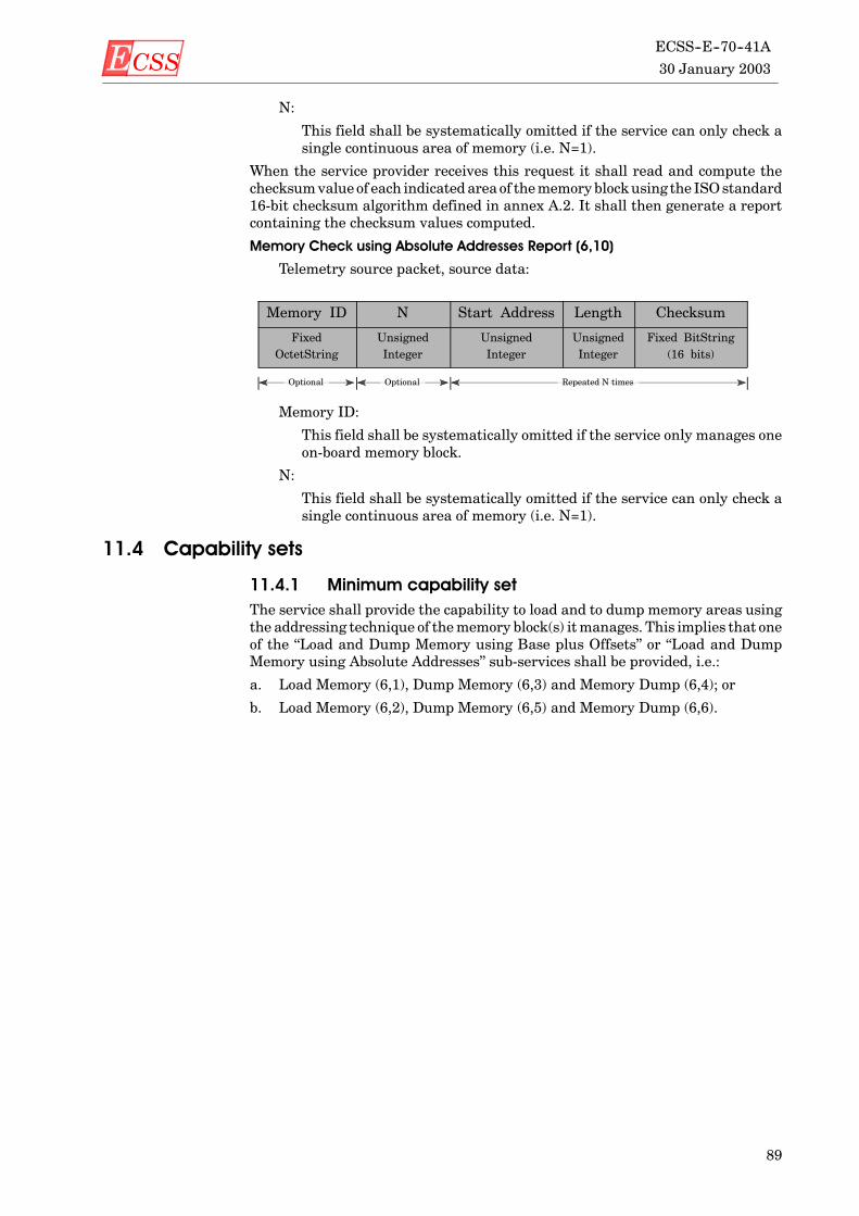
ECSS 30 January 2003
ECSS--E--70--41A
89
N:
This field shall be systematically omitted if the service can only check asingle continuous area of memory (i.e. N=1).
When the service provider receives this request it shall read and compute thechecksumvalue of each indicatedarea of thememoryblockusing the ISOstandard16-bit checksum algorithm defined in annex A.2. It shall then generate a reportcontaining the checksum values computed.
Memory Check using Absolute Addresses Report (6,10)
Telemetry source packet, source data:
Memory ID N Start Address Length Checksum
FixedOctetString
UnsignedInteger
UnsignedInteger
UnsignedInteger
Fixed BitString(16 bits)
Optional Optional Repeated N times
Memory ID:
This field shall be systematically omitted if the service only manages oneon-board memory block.
N:
This field shall be systematically omitted if the service can only check asingle continuous area of memory (i.e. N=1).
11.4 Capability sets
11.4.1 Minimum capability setThe service shall provide the capability to load and to dump memory areas usingthe addressing technique of thememory block(s) itmanages. This implies that oneof the “Load and Dump Memory using Base plus Offsets” or “Load and DumpMemory using Absolute Addresses” sub-services shall be provided, i.e.:
a. Load Memory (6,1), Dump Memory (6,3) and Memory Dump (6,4); or
b. Load Memory (6,2), Dump Memory (6,5) and Memory Dump (6,6).

ECSS30 January 2003ECSS--E--70--41A
90
11.4.2 Additional capability setsIn addition to aminimumsub-service, the additional capabilities given inTable 18can be implemented.
Table 18: Summary of memory management serviceadditional capabilities
Subtype Service request, report or capabilityRequiressubtype
1 Load Memory using Base plus Offsets 3 and 4
2 Load Memory using Absolute Addresses 5 and 6
3 Dump Memory using Base plus Offsets 1 and 4
4 Memory Dump using Base plus Offsets Report 3
5 Dump Memory using Absolute Addresses 2 and 6
6 Memory Dump using Absolute Addresses Report 5
7 Check Memory using Base plus Offsets 8
8 Memory Check using Base plus Offsets Report 7
9 Check Memory using Absolute Addresses 10
10 Memory Check using Absolute Addresses Report 9
Support of symbolic base references

ECSS 30 January 2003
ECSS--E--70--41A
91
12
Function management service
12.1 ScopeAn application processmay be designed to support software functions that are notimplemented as standard or mission-specific services but whose execution maynevertheless be controlled from the ground. Examples of such functions includecontrol of the operation of a payload instrument or a platform subsystem.
The function management service provides a standard service request forperforming the functions of the application process. This service satisfies thesoftware management concept described in subclause 4.6 of this Standard.
Anynumber of on-board application processesmay provide a single instance of thefunction management service.
Telemetry source packets and telecommand packets relating to the functionmanagement service shall be denoted by Service Type = 8.
12.2 Service conceptEach function within an application process shall be uniquely identified by a“Function ID”. The Function ID shall be assigned at the level of the individualcontrols for the corresponding function, e.g. load manoeuvre parameters, startmanoeuvre, stop manoeuvre, configure instrument to mode A, switch offinstrument etc. Where appropriate, a set of parameters pertaining to the givenfunction may also be provided.
12.3 Service requests and reports
12.3.1 GeneralThere are currently no service reports defined.

ECSS30 January 2003ECSS--E--70--41A
92
12.3.2 Perform functionThe request shall be:
Perform Function (8,1)
Telecommand packet, application data:
Function ID N Parameter# Value
Fixed CharString UnsignedInteger
Enumerated Deduced
Optional OptionalRepeated N times
Function ID:
The Function ID, together with the APID in the packet header, implicitlydefines the presence of, and the structure of, the fields which follow. Thelength of the character stringmay be defined on amission basis or per ap-plication process.
The internal structure of the Function ID is beyond the scope of this Stan-dard.
N:
The number of (Parameter#, Value) pairs which follow.
Parameter#:
The identification of the parameter whose value follows.
Value:
The value of the corresponding parameter (its type shall be deduced fromthe Parameter#).
The parameters shall be used to configure the specific instance of execution of theapplication function. Two options are available for supplying parameters (theoption is at Function ID-level, rather than at packet instance):
a. Only a subset of parameters is loaded. In this case, the packet shall containan array of the corresponding parameter numbers and values. Anyparameters not loaded shall retain their current values.
b. The full set of parameters is loaded. In this case, the packet shall contain adata structure (of parameter values) conforming to structure rules set #1 (seesubclause 23.6.2), where the structure is known implicitly.
In the latter case, the packet structure becomes simply:
Function ID Parameters
Fixed CharString Any
Optional
When this request is received, the specified function shall be performed using (orpassing) the specified parameters.

ECSS 30 January 2003
ECSS--E--70--41A
93
12.4 Capability sets
12.4.1 Minimum capability setThe minimum capability set shall consist of the service request given in Table 19.
Table 19: Summary of function management serviceminimum capabilities
Subtype Service request, report or capability
1 Perform Function
12.4.2 Additional capability setsThere are no additional capability sets.

ECSS30 January 2003ECSS--E--70--41A
94
(This page is intentionally left blank)

ECSS 30 January 2003
ECSS--E--70--41A
95
13
Time management service
13.1 ScopeAll satellites maintain a satellite time reference which can be downlinked bymeans of the “Time Report” defined in this clause. The ground segment canperformacorrelationbetweensatellite timeandUTC(universal timecoordinated)using, for example, the procedures described in annex C.
The time management service provides the (optional) capability for the control ofthe rate of generation of the time reports. This service option shall be used whena mission has varying requirements for time correlation accuracy.
This service satisfies the concepts described in subclause 4.5.4 of this Standard.
The two sub-services (rate control, time reporting) may be provided by differentapplication processes, however there shall be, at most, a single instance of each.The time reporting sub-service shall be provided by application process ID = 0 (seeannex C).
Telemetry source packets and telecommand packets relating to the timemanagement service shall be denoted by Service Type = 9.
13.2 Service conceptThe rate control sub-service shall maintain the generation rate (1, 2, 4, 8, 16, 32,64, 128 or 256) of the time report. It shall also have means of communicating thisgeneration rate to the time reporting sub-service.
The time reporting sub-service shall have access to the satellite time referencewhich is a free running counter from a given epoch (i.e. absolute time). Thesatellite time reference shall be sampled at the instant of occurrence of the leadingedge of the first bit of the attached synchronization marker of the telemetrytransfer frame of Virtual Channel 0 that has a virtual channel frame count of “0”and for each subsequent frame for which:
virtual channel frame count modulo (generation rate) = 0.
The time reporting sub-service shall then downlink this satellite time reference ina spacecraft time source packet at any time before the satellite time reference isnext sampled.
When a new generation rate is requested, the time reporting sub-service shall usethis new generation rate from the next telemetry transfer frame that meets theabove criterion.

ECSS30 January 2003ECSS--E--70--41A
96
13.3 Service requests and reports
13.3.1 Controlling the time report generation rateThe request for changing the rate of generation of the time report shall be:
Change Time Report Generation Rate (9,1)
Telecommand packet, application data:
Rate
Unsigned Integer(1 octet)
Rate:
This parameter determines the generation rate used to sample and down-link the satellite time. Its value shall be in the range 0 to 8 inclusive. Thecorresponding generation rate is equal to once every 2Rate telemetrytransfer frames.
When this request is received, the rate control sub-service shall inform the timereporting sub-service that a new time report generation rate shall be used.
13.3.2 Time reportingThe time report is the only provider-initiated service report defined for the timereporting sub-service.
As described in annex C, the spacecraft time source packet containing the timereport has no data field header.
Time Report (9,2)
Telemetry source packet, source data:
Rate Satellite Time Status
Unsigned Integer(1 octet)
Absolute Time Deduced
Optional Optional
Rate:
The rate field shall be systematically omitted if a mission has a fixed gen-eration rate.
Satellite Time:
This is the satellite time reference sampled according to the procedure de-scribed above. The format of this parameter shall be the CCSDS Unseg-mented Code (CUC) format with implicit or explicit P-Field (see CCSDS301.0--B--2). If the P-field is implicit, its value shall be given by themissionconstant <MISSION_TIME_CODE>.
Status:
This shall give the status of the time reporting sub-service. The type andvalues of the Status parameter are not specified in thisStandard. The typeand physical format are deduced from other information (see clause 23).
The Status field may be systematically omitted if a mission implements abasic time reporting sub-service.

ECSS 30 January 2003
ECSS--E--70--41A
97
13.4 Capability sets
13.4.1 Minimum capability setsThe rate control sub-service is an optional capability, but a pre-requisite is that thetime reporting sub-service is also provided. The minimum capability set for therate control sub-service shall consist of the service request given in Table 20.
Table 20: Summary of rate control sub-service minimumcapabilities
Subtype Service request, report or capability
1 Change Time Report Generation Rate
Asnoted earlier, the time reporting sub-servicemay only be provided byAPID = 0.The minimum capability set for the time reporting sub-service shall consist of theservice report given in Table 21.
Table 21: Summary of time reporting sub-serviceminimum capabilities
Subtype Service request, report or capability
2 Time Report
NOTE Transmission of the spacecraft time source packet to theground is enabled and disabled using the packet forwardingcontrol service (see clause 17).
13.4.2 Additional capability setsThere are no additional capability sets.

ECSS30 January 2003ECSS--E--70--41A
98
(This page is intentionally left blank)
ECSS 30 January 2003
ECSS--E--70--41A
99
14
On-board operations scheduling service
14.1 ScopeThe on-board operations scheduling service provides the capability to commandon-board application processes using telecommands pre-loaded on-board thesatellite and released at their due time. To achieve this, the service maintains anon-board command schedule and ensures the timely execution of telecommandscontained therein.
This service satisfies the concepts described in subclause 4.7 of this Standard.
Anynumber of on-board application processesmay provide a single instance of theon-board operations scheduling service.
Telemetry source packets and telecommand packets relating to the on-boardoperations scheduling service shall be denoted by Service Type = 11.
14.2 Service concept
14.2.1 GeneralThe on-board operations scheduling service shall maintain a command schedulewhich contains telecommand packets and their associated scheduling informa-tion.
The service user(s) can request the following activities:
a. Enable the scheduling of all, or a subset of, the telecommands in the commandschedule (e.g. those to be sent to specified application processes).
b. Disable the scheduling of all, or a subset of, the telecommands in the commandschedule.
c. Add telecommands to the command schedule.
d. Delete all, or a subset of, the telecommands in the command schedule (e.g. thetelecommands becoming due for release within a specified time period).
e. Time shift all, or a subset of, the telecommands in the command schedule.
f. Report on all, or a subset of, the telecommands in the command schedule.
g. Report the status of the command schedule.
Inconsistencies shall not exist as a direct result of the processing of a service userrequest. The on-board operations scheduling service shall refuse to perform arequest in its entirety if this creates an inconsistency in the command schedule.

ECSS30 January 2003ECSS--E--70--41A
100
The service user(s) shall be responsible for ensuring that inconsistencies whichcan only be detected during the scheduling activity shall never occur.
14.2.2 The command scheduleThe on-board operations scheduling service maintains a command scheduleconsisting of telecommand packets together with their scheduling attributes. Thescheduling attributes of a telecommand indicate the following:
a. The sub-schedule with which the telecommand is associated. A sub-scheduleis a groupingmechanism for telecommands that enables them to be controlledtogether or interlocked to others in the same group (see point b. below).
b. The number of the interlock to be set by this telecommand, if any. The successor failure of execution of the telecommand is associated with the specifiedinterlock. Interlocking is restricted to commands belonging to the samesub-schedule.
c. The number of the interlock on which the release of this telecommand isdependent, if any.
d. Whether the release of this telecommand isdependent on the success or on thefailure of the telecommand with which it is interlocked.
e. Either the absolute on-board time at which the telecommand packet isreleased to its destination application process or a relative time (if supported).
Absolute times and relative times shall be expressed in CUC format for theon-board operations scheduling service.
Relative time shall be defined with respect to a “Scheduling Event” which can bethe starting of the command schedule, the starting of the sub-schedule containingthe telecommand or the setting of the interlock with which the telecommand isinterlocked (i.e. when the service is notified of the success or failure of thetelecommand which sets the interlock).
The scheduling event for relative time can also be the occurrence of amission-specific event.
The on-board operations scheduling service shall know, therefore, if an interlock-ing telecommand defines a scheduling event for other subsequent interlockedtelecommands. In this case the actual time of completion of command executionshall be used for the derivation of the release times of the subsequenttelecommands.
14.2.3 Telecommand release statusThe on-board operations scheduling service shall maintain appropriate informa-tion to determinewhether a telecommand should be released ornot at its due time.
The release status of a telecommand shall be affected by the user requests toenable or disable the release of all or a subset of the telecommands in the commandschedule. The telecommand release status shall be either “disabled” or “enabled”.
The release status of a telecommand shall be “enabled” if the release oftelecommands is enabled from the command schedule, from the sub-schedule towhich the telecommand belongs, and to the destination application process of thetelecommand.
The release status shall be “disabled” in all other cases.
Conceptually, this is as if each telecommand has three independent controllingattributes (at schedule level, at sub-schedule level and at destination applicationprocess level) whose values determine the release status of the telecommand inaccordance with Table 22.

ECSS 30 January 2003
ECSS--E--70--41A
101
Table 22: Decision table for the release status of atelecommand
Schedule Sub-schedule
Destinationapplicationprocess Release status
D(isabled) E(nabled) E D
D D E D
D E D D
D D D D
E E E E
E D E D
E E D D
E D D D
14.2.4 Telecommand interlock statusThe execution result of a telecommand which sets an interlock shall be used inorder to determine the interlock status of the telecommands which are due forrelease.
The execution result of a telecommand can be “success” or “failure”.
When a telecommand which sets an interlock is due for release, then:
a. if its release status is “disabled” or its interlock status is “locked”, thetelecommand shall not be released and its execution result shall be set to“failure”;
b. otherwise the telecommand shall be released and its execution result areunknown until the execution of the telecommand is completed.
The on-board operations scheduling service shall explicitly indicate to thedestination application process that the released telecommand sets an interlockso that, when the telecommand execution is complete, an execution report shall bepassed back to the service.
On reception of this report, the service shall set the telecommand execution resultaccordingly (“success” or “failure”).
If the execution completion report is not received after the maximum executionduration of the telecommand has elapsed, then the telecommand execution resultshall be set to “failure”.
When a telecommand is due for release and its release depends on an interlock,its interlock status is evaluated as follows:
D If the release of the telecommand depends on the success of the telecommandsetting the interlock and the telecommand execution result attached to theinterlock is “failure”, then it shall be “locked”.
D If the release of the telecommand depends on the failure of the telecommandsetting the interlock and the telecommand execution result attached to theinterlock is “success”, then it shall be “locked”.
This is illustrated in Figure 5 in which “1+” means “release depends on thesuccessful execution of the telecommand setting interlock number 1” and “1-”means the opposite.

ECSS30 January 2003ECSS--E--70--41A
102
Clear to go
Locked
Clear to go
Locked
Locked
Clear to go
Success
Failure
1
2
3
1+
2-
3+
3+
1-
Telecommand 1
InterlockSet
ExecutionResult
InterlockAssessed
InterlockStatus
Telecommand 2
Telecommand 3
Telecommand 4
Telecommand 5
Telecommand 6
Telecommand 7
Failure
3-
Figure 5: The relation between execution result and interlock status
14.2.5 Scheduling eventsThe on-board operations scheduling service shall determine the times ofoccurrence of the various scheduling events used as the basis for relative releasetimes, namely:
a. The on-board CUC time at which the command schedule was enabled.
b. The on-board CUC time at which a sub-schedule was enabled, for eachsub-schedule which contains telecommands whose release time is relative tothe sub-schedule enable time.
c. The on-board CUC time of reception of the execution completion report (or ofoccurrence of the execution completion timeout), for each interlockingtelecommand whose execution completion is a scheduling event for subse-quent telecommands.
NOTE As soon as a scheduling event has occurred, all telecom-mands whose scheduled time is relative to that schedulingevent have a known absolute schedule time. If the samescheduling event recurs, this does not affect the absolutetimes of these telecommands.
The on-board operations scheduling service shall refuse to add or time-shifttelecommands if this results in an interlock-dependent telecommand appearingbefore the execution completion timeout defined for its interlocking telecommand.This ensures that the execution result of the interlocking telecommand is knownwhen the release of the interlock-dependent telecommand is due.

ECSS 30 January 2003
ECSS--E--70--41A
103
The service user(s) should also ensure that this situation never occurs in the casewhere it cannot be detected at the time of processing of a service request (e.g. bydetermining the maximum execution duration of all telecommand paths leadingto an interlock-dependent telecommand with absolute time).
14.2.6 Auxiliary informationThe on-board operations scheduling service shall also have access to otherinformation needed for the proper execution of its activities. This includes:
a. Themaximum number of entries or maximum size of the command schedule.
b. The maximum number of sub-schedules which can be simultaneouslymanaged.
c. The maximum number of interlocks which can be simultaneously managed.
d. The list of sources from which the service can receive telecommand packetsto be scheduled.
e. The list of on-board application processes to which the service can releasetelecommand packets.
The service shall use this information for error detection and reporting.
14.2.7 The scheduling activityThe processing of a telecommand packet whose release time is due shall alwaysbe performed (even if the command schedule is disabled).
The corresponding service activity shall be:
a. The telecommand shall not be released if the telecommand release status is“disabled” or the telecommand interlock status is “locked”. If the telecommanddefines a scheduling event, the scheduling event time shall be the currenttime. If the telecommand sets an interlock, the execution result shall be setto “failure”.
b. Otherwise, the telecommand shall be released. Where applicable, itsexecution result shall then be determined as indicated in subclause 14.2.4and the time of its scheduling event shall be determined as indicated insubclause 14.2.5.
In addition to this primary activity, any on-board CUC time jumps shall bedetected and reported.
On detection of a time jump, the service shall suspend its execution as soon as ithas processed (including releasing) all the telecommands which are interlockedwith telecommands which have already been released (if any).
14.3 Service requests and reports
14.3.1 Controlling the command schedule
14.3.1.1 General
There are several ways of enabling or disabling the release of a subset of thetelecommands in the command schedule. The subsets are specified according toselection criteria.
EXAMPLE Telecommands with specified destination application pro-cesses.
If an error is detected during the processing of a request, it shall not affect theprocessing of the remainder of the request.

ECSS30 January 2003ECSS--E--70--41A
104
14.3.1.2 Controlling the release of telecommands
The service requests to enable or disable the release of selected telecommandsshall be:
Enable Release of Telecommands (11,1)
Telecommand packet, application data:
Disable Release of Telecommands (11,2)
Telecommand packet, application data:
N1 Sub-schedule ID N2 Application Process ID
UnsignedInteger
Enumerated UnsignedInteger
Enumerated
Optional OptionalRepeated N2 times
Repeated N1 times
N1:
This field shall be systematically omitted if the service does not supportthe concept of sub-schedules (which is equivalent to having N1=1). In thiscase, the Sub-schedule ID field shall also be omitted and the applicationdata is simply an array of N2 APIDs.
Sub-schedule ID:
The identification of the sub-schedule(s) to be enabled or disabled. By con-vention, the value 0 for Sub-schedule ID shall mean “all sub-schedules”.
This field shall be systematically omitted if the service does not supportthe concept of sub-schedules.
N2:
This field shall be systematically omitted if the service does not supportselection at application process level (which is equivalent to havingN2=0).
Application Process ID:
The identification of the destination application process(es) to be enabledor disabled.
When the service provider receives this request, then:
a. If N1 = 0, the schedule level controlling attribute of all telecommands (seesubclause 14.2.3) shall be set according to the request type. If it is an enablerequest, then the command schedule scheduling event time shall also be set.
b. If N1 > 0 and N2 = 0, the sub-schedule level controlling attribute of thetelecommands from the specified sub-schedules shall be set according to therequest type. If it is an enable request, then the scheduling event times of thesub-schedules shall also be set.
c. If N1 > 0 and N2 > 0, the application process level controlling attribute of thetelecommands with the specified destination application processes and withthe specified sub-schedules shall be set according to the request type.
NOTE IfN1>1 then there canbeamixture of empty arrays (N2 = 0)and non-empty arrays (N2 > 0).

ECSS 30 January 2003
ECSS--E--70--41A
105
14.3.1.3 Resetting the command schedule
The request shall be:
Reset Command Schedule (11,3)
Telecommand packet, application data: None.
When the service provider receives this request, it shall reset the commandschedule as follows (this is considered to be the “default” starting state):
a. It shall clear all entries in the command schedule. The command scheduleshall be disabled, all sub-schedules shall be disabled and commanding to allapplication processes shall be enabled.
b. It shall reset the interlock information (no interlock defined).
c. It shall reset the scheduling event information (all scheduling event timesshall be unknown).
14.3.2 Inserting telecommands in the command scheduleThe request to insert (e.g. add) one or more telecommands in the CommandSchedule shall be:
Insert Telecommands in Command Schedule (11,4)
Telecommand packet, application data:
Sub-schedule ID N
Enumerated Unsigned Integer
Optional Optional
InterlockSet ID
InterlockAssessed ID
AssessmentType
SchedulingEvent
Abs/RelTime Tag
ExecutionTimeout
TelecommandPacket
Enumerated Enumerated Enumerated Enumerated Absolute orRelative Time
RelativeTime
Any TC
Optional Optional Optional OptionalRepeated N times
Sub--schedule ID:
The identification of the sub-schedule with which the following telecom-mands are associated. The Sub-schedule ID cannot take the value 0.
This field shall be systematically omitted if the service does not supportthe concept of sub-schedules.
N:
The number of telecommands to be inserted in the schedule.
This field shall be systematically omitted if the service only supports theinsertion of a single telecommand at a time.
Interlock Set ID:
The identification of the interlock to be set by this telecommand (0 if nointerlock is set). The status of this interlock shall be determinedby the suc-cess or failure of the telecommand execution.
This field shall be systematically omitted if the service does not supportthe concept of interlocking.
Interlock Assessed ID:
The identification of the interlock on which the release of this telecom-mand is dependent (0 if no interlock is assessed).

ECSS30 January 2003ECSS--E--70--41A
106
This field shall be systematically omitted if the service does not supportthe concept of interlocking.
Assessment Type:
Whether the release of this telecommand is dependent on the success orfailure of the telecommand with which it is interlocked, viz.:
“Success” (value = 1): release if interlocking telecommand was successful;
“Failure” (value =0): release if interlocking telecommand failed execution.
This parameter shall not be present if the telecommand isnot interlockde-pendent (or if the service does not support the concept of interlocking).
Scheduling Event:
This determineswhether the release time of this telecommand shall be anabsolute on-board CUC time (Scheduling Event = “Absolute”, value = 0)or a relative time and, in the latter case, this parameter indicates the typeof scheduling event for the relative time.
If the Scheduling Event = “Schedule” (value = 1), the telecommand releasetime shall be relative to the time at which the command schedule is en-abled.
If the SchedulingEvent = “Sub-Schedule” (value =2), the telecommand re-lease time shall be relative to the time at which the sub-schedule contain-ing the telecommand is enabled.
If the Scheduling Event = “Interlock” (value = 3), then the telecommandrelease time shall be relative to the time of notification to the service of thesuccess or failure of the telecommand which sets the interlock.
The Scheduling Event can take other mission-specific values.
This field shall be systematically omitted if the service does not supportthe concept of relative time.
Abs/Rel Time Tag:
If Scheduling Event = “Absolute”, then this is the on-board CUC time atwhich the telecommand packet shall be sent to its destination applicationprocess. The format and length of this field shall be uniquely defined forthe on-board application process which provides the service and shall beusedwhenever an absolute time tag is provided as a parameter of a servicerequest or report.
If the Scheduling Event indicates a relative time, then this shall be an on-board positive delta time which, when added to the time of occurrence ofthe event identified by the SchedulingEvent, shall determine the absolutetime at which the telecommand packet shall be sent to its destination ap-plication process. The format and length shall be the same as for the abso-lute time tag and shall be uniquely defined for the on-board applicationprocess which provides the service.
Execution Timeout:
This shall be an on-board positive delta time which, when added to thetime of release of the telecommand, shall determine the latest time atwhich the execution of the telecommand is expected to complete. Thisparameter shall only be present if the telecommand sets an interlock.
If an execution completion report is not received by the service within thetimeout window, then the telecommand shall be deemed to have failed forthe purposes of handling the interlock. Also, if the completion of executionof the telecommand constitutes a scheduling event, then the schedulingevent time shall be set to the timeout window upper bound. The absolutetimes of the telecommands linked to this scheduling event shall then be-come known.
ECSS 30 January 2003
ECSS--E--70--41A
107
The format and length of this field shall be the same as for the absolutetime tag defined for the on-board application process which provides theservice.
Telecommand Packet:
This is a standard telecommand packet of any service type and subtype,(see subclause 5.3 for the structure of a telecommand). This can be a tele-command destined for an on-board operations scheduling service, eitherthis one or another instance of the same service implemented in anotherapplication process (e.g. a request to enable or disable sub-scheduleswith-in the command schedule).
The source of the telecommand packet shall be indicated in the Source IDfield (when present in the data field header). This can be the ground sys-tem or another on-board application process.
If a telecommand to be added has a relative time with respect to an interlock, itshall be “linked” to the latest telecommand added to the command schedule whichsets that interlock.
When this request is received, each telecommand in the request shall be processedin turn and, if no error is detected during its processing, it shall be added to thecommand schedule.
An error shall occur, if:
a. the command schedule is full;
b. the Sub-schedule ID or one of the Interlock IDs exceeds its maximum value;
c. the Interlock IDs are equal;
d. the destination application process of the telecommand is invalid;
e. the time specification refers to the past;
f. the time specification is not supported by the service;
g. the telecommand is interlock dependent and its release time falls within theexecution window of its interlocking telecommand;
h. the telecommand has an “Interlock” relative time and no telecommand addedsince the last resetting of the command schedule sets the interlock.
14.3.3 Deleting telecommands from the command schedule
14.3.3.1 General
There are several ways of deleting a subset of the telecommands from thecommand schedule. The subsets are specified according to selection criteria.
EXAMPLE Telecommands whose absolute schedule time falls within aspecified time period.
The scheduling service shall refuse to delete an interlocking telecommand unlessall its (directly and indirectly) interlocked telecommands have either already beendeleted or are deleted in the same deletion request.
A service user can delete telecommands originating from different sources,however in practice there can be restrictions on which source(s) request this.
If an error is detected during the processing of a request, nothing shall be deleted.

ECSS30 January 2003ECSS--E--70--41A
108
14.3.3.2 Deleting telecommands
The request to delete sets of telecommands from the command schedule shall be:
Delete Telecommands (11,5)
Telecommand packet, application data:
NApplicationProcess ID
SequenceCount
Number ofTelecommands
UnsignedInteger
Enumerated UnsignedInteger
UnsignedInteger
Optional Repeated N times
N:
This field shall be systematically omitted if the service does not supportthe concept of “scatter delete” (i.e. N=1).
Sequence Count:
The sequence count of the first telecommand packet to be sent to the speci-fied destination application process which shall be deleted.
The (APID, Sequence Count) pair uniquely identifies a telecommandpacket. These parameters shall correspond to the packet header fields ofeach telecommand packet as defined in subclause 5.3.
Number of Telecommands:
The number of successive telecommand packets sent by the source to thespecified destination application process which shall be deleted.
When this request is received, all telecommands which satisfy the selectioncriteria defined by the APID, Sequence Count and the Number of Telecommandsshall be deleted. An error shall occur if the first telecommand to be deleted is notfound in the command schedule. If theNumber of Telecommands exceeds the totalnumber of commands that satisfy the selection criteria, then all commands thatsatisfy the selection criteria shall be deleted.
The deletion of telecommands which have times relative to scheduling eventswhichhavenot yet occurred can only beperformedbymeansof this type of request.
14.3.3.3 Deleting telecommands over a time period
The request shall be:
Delete Telecommands over Time Period (11,6)
Telecommand packet, application data:
Range Time Tag 1 Time Tag 2 N1 Sub-scheduleID
N2 ApplicationProcess ID
Enumerated Absolute Time Absolute Time UnsignedInteger
Enumerated UnsignedInteger
Enumerated
Optional Optional Optional Repeated N2 timesOptional
Repeated N1 times
Range:
This indicates that the time period is:
(a) from the beginning to the end of the command schedule if Range is“All” (value = 0); or
(b) between Time Tag 1 and Time Tag 2 inclusive if Range is “Between”(value = 1); or

ECSS 30 January 2003
ECSS--E--70--41A
109
(c) less than or equal to Time Tag 1 if Range is “Before” (value = 2); or
(d) greater than or equal to Time Tag 1 if Range is “After” (value = 3).
The service may only support limited values of Range.
Time Tag 1:
The earliest absolute time if Range is “Between” or “After”. The latest ab-solute time if Range is “Before”. This parameter shall not be present ifRange is “All”.
Time Tag 2:
The latest absolute time if Range is “Between”. This parameter shall notbe present if Range is not “Between”.
N1:
This field shall be systematically omitted if the service does not supportthe concept of sub-schedule or the concept of selection at sub-schedulelevel. In this case, the Sub-schedule ID field shall also be omitted.
Sub-schedule ID:
The identification of the sub-schedule(s) from which telecommands shallbe deleted. By convention, the value 0 for Sub-schedule ID shall mean “allsub-schedules”.
N2:
This field shall be systematically omitted if the service does not supportthe concept of selection at application process level. In this case, the APIDfield shall also be omitted.
Application Process ID:
The identification of the destination application process(es) from whichtelecommands shall be deleted.
When this request is received, the following telecommands shall be deleted if theyhave release times falling in the specified absolute time period:
a. if N1 = 0, all telecommands;
b. if N1 > 0 and N2 = 0, those telecommands which belong to the specifiedsub-schedules;
c. if N1>0andN2>0, those telecommandswhich have the specified destinationapplication processes and belong to the specified sub-schedules.
Those telecommands whose absolute release times are not yet known shall not bedeleted fromthe command schedule.A telecommandhasanunknownrelease timeif it has a time relative to (directly or indirectly) a scheduling event which has notyet occurred.
However, if telecommand B has a time relative to the completion of execution oftelecommand A which itself has not yet completed execution but which has aknown release time then the release time of telecommand B shall be evaluatedunder the assumption that the execution duration of telecommand A is zero.
14.3.4 Time-shifting of telecommands in the commandschedule
14.3.4.1 General
There are several ways of time-shifting a subset of the telecommands in thecommand schedule.The time-shift request shall contain the time offset to beadded(which can be a positive or negative value) and shall specify the selection oftelecommands to which this time-offset is applied.
The scheduling service shall refuse to time-shift a telecommand if its newabsolutetime would fall in the past or before the end of the execution window of its

ECSS30 January 2003ECSS--E--70--41A
110
interlocking telecommand (if it is interlock dependent) or if its new relative timewould become negative.
A service user can time-shift telecommands originating from different sources,however in practice there can be restrictions on which source(s) request this.
If an error is detected during the processing of a request, nothing shall betime-shifted.
14.3.4.2 Time-shifting all telecommands
The request to time-shift all telecommands in the command schedule shall be:
Time-Shift All Telecommands (11,15)
Telecommand packet, application data:
Time Offset
Relative Time
Time Offset:
A positive or negative interval of time expressed in the length and formatof relative time defined for the service or mission (since it is the relativetime between the new and the old values of release time).
When this request is received, the release times for all telecommands in thecommand schedule which have an absolute release time shall be modified byadding the specified time offset.
Those telecommands whose absolute release times are not yet known are nottime-shifted. A telecommand has an unknown release time if it has a time relativeto (directly or indirectly) a scheduling event which has not yet occurred.
14.3.4.3 Time-shifting selected telecommands
The request to time-shift a selected subset of telecommands in the commandschedule shall be:
Time-Shift Selected Telecommands (11,7)
Telecommand packet, application data:
TimeOffset
N ApplicationProcess ID
SequenceCount
Number ofTelecommands
RelativeTime
UnsignedInteger
Enumerated UnsignedInteger
UnsignedInteger
Optional Repeated N times
N:
This field shall be systematically omitted if the service does not supportthe concept of “scatter time-shift” (i.e. N=1).
When this request is received the release times in the command schedule shall betime-shifted for those telecommands which meet the selection criteria defined bythe specified APID, Sequence Count andNumber of Telecommands.An error shalloccur if the first telecommand to be time-shifted is not found in the commandschedule. Those telecommands whose absolute release times are not yet knownare not time-shifted. A telecommand has an unknown release time if it has a timerelative to (directly or indirectly) a scheduling event which has not yet occurred.

ECSS 30 January 2003
ECSS--E--70--41A
111
14.3.4.4 Time-shifting selected telecommands over a time period
The request shall be:
Time-Shift Selected Telecommands over Time Period (11,8)
Telecommand packet, application data:
Range Time Tag 1 Time Tag 2 Time Offset
Enumerated AbsoluteTime
AbsoluteTime
Relative Time
Optional Optional
N1 Sub-scheduleID
N2 ApplicationProcess ID
UnsignedInteger
Enumerated UnsignedInteger
Enumerated
Optional OptionalRepeated N2 times
Repeated N1 times
Range:
The service may only support particular values of Range.
N1:
This field shall be systematically omitted if the service does not supportthe concept of sub-schedule (which is equivalent to having N1=1). In thiscase, the Sub-schedule ID field shall also be omitted.
N2:
This field shall be systematically omitted if the service does not supportthe selective time-shifting of telecommands in a time range (which isequivalent to having N2=0).
By convention, the value 0 for Sub-schedule ID shall mean “all sub-schedules”.
When this request is received, the release times of the following telecommandsshall be time-shifted if they have release times falling in the specified absolutetime period:
a. if N1 = 0, all telecommands;
b. if N1 > 0 and N2 = 0, those telecommands which belong to the specifiedsub-schedules;
c. if N1>0andN2>0, those telecommandswhich have the specified destinationapplication processes and belong to the specified sub-schedules.
Those telecommands whose absolute release times are not yet known are nottime-shifted. A telecommand has an unknown release time if it has a time relativeto (directly or indirectly) a scheduling event which has not yet occurred.

ECSS30 January 2003ECSS--E--70--41A
112
14.3.5 Reporting of the command schedule contents
14.3.5.1 General
There are several ways of reporting a subset of the telecommands in the commandschedule. The requests shall indicate whether a summary or detailed report isproduced.
The reports shall contain information on telecommands originating from allsources. The information shall be ordered according to the predicted times oftelecommand release.
Only those telecommands shall be reported for which the time of release has notyet expired.
Telecommands can be released between the reception of the service request andthe completion of the service report.However, the report shall contain a consistentview which reflects the situation at the report packet time.
14.3.5.2 Detailed reporting of the command schedule
The request to obtain a detailed report of all telecommands in the commandschedule shall be:
Report Command Schedule in Detailed Form (11,16)
Telecommand packet, application data: None
When this request is received, a detailed schedule report (see below) shall begenerated containing all telecommands in the command schedule.
The request to obtain a detailed report of a selected subset of telecommands in thecommand schedule shall be:
Report Subset of Command Schedule in Detailed Form (11,9)
Telecommand packet, application data:
N ApplicationProcess ID
SequenceCount
Number ofTelecommands
UnsignedInteger
Enumerated UnsignedInteger
UnsignedInteger
Optional Repeated N times
N:
This field shall be systematically omitted if the service does not supportthe concept of “scatter report” (i.e. N=1).
When this request is received, a detailed schedule report shall be generatedcontaining those telecommands in the command schedule which meet theselection criteria defined by the combination of APID, Sequence Count andNumber of Telecommands. An error shall occur if the first telecommand to bereported is not found in the command schedule.
The detailed schedule report shall contain all the static scheduling attributes forthe selected telecommands. Telecommands whose release time is not yet knowncan only be selectively reported by means of this type of request.

ECSS 30 January 2003
ECSS--E--70--41A
113
Detailed Schedule Report (11,10)
Telemetry source packet, source data:
N Sub-scheduleID
InterlockSet ID
InterlockAssessed ID
AssessmentType
UnsignedInteger
Enumerated Enumerated Enumerated Enumerated
Optional Optional OptionalRepeated N times
SchedulingEvent
Abs/RelTime Tag
ExecutionTimeout
TelecommandPacket
Enumerated Absolute orRelative Time
RelativeTime
Any TC
Optional OptionalRepeated N times (contd.)
Sub-schedule ID:
This field shall be systematically omitted if the service does not supportthe concept of sub-schedules.
Interlock Set ID, Interlock Assessed ID:
These fields shall be systematically omitted if the service does not supportthe concept of interlocking.
Scheduling Event:
This field shall be systematically omitted if the service does not supportthe concept of relative time.
Relative time shall be placed in the report when the absolute release time of thetelecommand is still unknown (e.g. even if its release is relative to completion ofexecution of another telecommand whose release time is known but whoseexecutionhasnot yet started or isnot yet complete). The corollary is that the reportcan indicate an “Absolute” time even though a relative time was originally loadedfor the corresponding telecommand. This happens if the event to which therelative time relates has occurred in the meantime. The service shall thenelaborate the relative time to an absolute time and it can report it as such.
14.3.5.3 Summary reporting of the command schedule
The request to obtain a summary report of all telecommands in the commandschedule shall be:
Report Command Schedule in Summary Form (11,17)
Telecommand packet, application data: None
When this request is received, a summary schedule report (see below) shall begenerated containing all telecommands in the command schedule.
The request to obtain a summary report of a selected subset of telecommands inthe command schedule shall be:
Report Subset of Command Schedule in Summary Form (11,12)
Telecommand packet, application data: Same as for the “Report CommandSchedule in Detailed Form” service request.
When this request is received, a report shall be generated containing thosetelecommands in the command schedule whichmeet the selection criteria definedby the combination of APID, Sequence Count and Number of Telecommands. An

ECSS30 January 2003ECSS--E--70--41A
114
error occurs if the first telecommand to be reported is not found in the commandschedule.
The summary schedule report shall contain only the identifications for theselected telecommands. Telecommands whose release time is not yet known canonly be selectively reported by means of this type of request.
Summary Schedule Report (11,13)
Telemetry source packet, source data:
NSub-schedule
IDSchedulingEvent
Abs/RelTime Tag
ApplicationProcess ID
SequenceCount
UnsignedInteger
Enumerated Enumerated Absolute orRelative Time
Enumerated UnsignedInteger
Optional OptionalRepeated N times
14.3.5.4 Detailed reporting of the command schedule over a time period
The request for a detailed report of a selected subset of the command schedule overan absolute time period shall be:
Report Subset of Command Schedule in Detailed Form over Time Period (11,11)
Telecommand packet, application data:
RangeTimeTag 1
TimeTag 2
N1 Sub-scheduleID
N2 ApplicationProcess ID
Enumerated AbsoluteTime
AbsoluteTime
UnsignedInteger
Enumerated UnsignedInteger
Enumerated
Optional Optional Optional OptionalRepeated N2 times
Repeated N1 times
Range:
The service may only support particular values of Range.
N1:
This field shall be systematically omitted if the service does not supportthe concept of sub-schedule (which is equivalent to having N1=1). In thiscase, the Sub-schedule ID field shall also be omitted.
N2:
This field shall be systematically omitted if the service does not supportthe selective reporting of telecommands in a time range (which is equival-ent to having N2=0).
When this request is received, a Detailed Schedule Report (as defined insubclause 14.3.5.2) shall be generated. The report shall cover the followingtelecommands if they have release times fallingwithin the specified absolute timeperiod:
a. if N1 = 0, all telecommands;
b. if N1 > 0 and N2 = 0, those telecommands which belong to the specifiedsub-schedules;
c. if N1>0andN2>0, those telecommandswhich have the specified destinationapplication processes and belong to the specified sub-schedules.
Telecommands whose absolute release times are not yet known shall not beincluded in the report.A telecommandhasanunknownrelease time if it has a timerelative to (directly or indirectly) a scheduling event which has not yet occurred.

ECSS 30 January 2003
ECSS--E--70--41A
115
However, if telecommand B has a time relative to the completion of execution oftelecommand A which itself has not yet been executed but which has a knownrelease time, then the release time of telecommandB shall be evaluated under theassumption that the execution duration of telecommand A is zero.
14.3.5.5 Summary reporting of the command schedule over a timeperiod
The request for a summary report of a selected subset of the command scheduleover an absolute time period shall be:
Report Subset of Command Schedule in Summary Form over Time Period (11,14)
Telecommand packet, application data: Same as for the “Report CommandSchedule in Detailed Form over Time Period” service request.
When this request is received, a summary schedule report (as defined insubclause 14.3.5.3) shall be generated. The report shall cover the telecommandswhich meet the same selection criteria as defined in subclause 14.3.5.4.
14.3.6 Reporting of the status of the command scheduleThe request to report the status of the command schedule shall be:
Report Status of Command Schedule (11,18)
Telecommand packet, application data: None
When this request is received, a report shall be generated containing the status(enabled or disabled) of the individual sub-schedules and application processeswithin each sub-schedule.
Command Schedule Status Report (11,19)
Telemetry source packet, source data:
N1 Sub-scheduleID
Status N2 ApplicationProcess ID
Status
UnsignedInteger
Enumerated Enumerated UnsignedInteger
Enumerated Enumerated
Optional Repeated N2 timesRepeated N1 times
N1:
This field shall be systematically omitted if the service does not supportthe concept of sub-schedules (which is equivalent to having N1=1). In thiscase, the Sub-schedule ID field and the Status fields shall also be omittedand the application data is simply an array of N2 APIDs + Statuses.
Sub-schedule ID:
The identification of the sub-schedule being reported.
Status:
The status of the corresponding sub-schedule, as follows:
value = 0 (Disabled)
value = 1 (Enabled).
Application Process ID:
The identification of the applicationprocesswithin the corresponding sub-schedule being reported.

ECSS30 January 2003ECSS--E--70--41A
116
Status:
The status of the corresponding application process, as follows:
value = 0 (Disabled)
value = 1 (Enabled).
14.4 Capability sets
14.4.1 Minimum capability setTheminimum capability set shall consist of the service requests and reports givenin Table 23, but some of them only with particular combinations of parameters asspecified in the subclauses above.
Table 23: Summary of on-board operations schedulingservice minimum capabilities
Subtype Service request, report or capability
1 Enable Release of Telecommands
2 Disable Release of Telecommands
3 Reset Command Schedule
4 Insert Telecommands in Command Schedule
14.4.2 Additional capability setsAn on-board operations scheduling service can implement the additionalcapabilities given in Table 24.
Table 24: Summary of on-board operations schedulingservice additional capabilities
SubtypeService request, report orcapability Requires subtype
Support of sub-schedules “Sub-schedule ID” insubtypes 4, 10 and13N1 and correspondingarray in subtypes 1and 2
Support of one or more types ofrelative times
“Scheduling Event” insubtypes 4, 10 and13
Support of the interlocking commandconcept
“Interlock Set ID”and “InterlockAssessed ID” insubtypes 4 and 10
Support of “scatter” delete, time-shiftand report
N and correspondingarray in subtypes 5,7, 9 and 12
Support of telecommand selectionstrategy at sub-schedule level
“Sub-schedule ID” insubtypes 6, 8, 11 and14

ECSS 30 January 2003
ECSS--E--70--41A
117
Table 24: Summary of on-board operations schedulingservice additional capabilities (continued)
Subtype Requires subtypeService request, report orcapability
Support of telecommand selectionstrategy at application process level
N2 and correspondingarray in subtypes 1,2, 6, 8, 11 and 14
5 Delete Telecommands
6 Delete Telecommands over TimePeriod
5
15 Time-Shift All Telecommands
7 Time-Shift Selected Telecommands 15
8 Time-Shift Telecommands over TimePeriod
7 and 15
16 Report Command Schedule inDetailed Form
10
9 Report Subset of Command Schedulein Detailed Form
10 and 16
10 Detailed Schedule Report 16 and/or 9 and/or11
11 Report Subset of Command Schedulein Detailed Form over Time Period
9, 10 and 16
17 Report Command Schedule inSummary Form
13
12 Report Subset of Command Schedulein Summary Form
13 and 17
13 Summary Schedule Report 17 and/or 12 and/or14
14 Report Subset of Command Schedulein Summary Form over Time Period
12, 13 and 17
18 Report Status of Command Schedule 19
19 Command Schedule Status Report 18

ECSS30 January 2003ECSS--E--70--41A
118
(This page is intentionally left blank)

ECSS 30 January 2003
ECSS--E--70--41A
119
15
On-board monitoring service
15.1 ScopeThe on-board monitoring service provides the capability to monitor on-boardparameters with respect to checks defined by the ground system and reports anycheck transitions to the service user. Optionally, an event reportmay be generatedas the result of a givenmonitoring violation. To achieve this, the servicemaintainsa monitoring list and checks parameter samples according to the informationcontained therein.
This service satisfies the concepts described in subclause 4.8 of this Standard.
Anynumber of on-board application processesmay provide a single instance of theon-board monitoring service.
Telemetry source packets and telecommand packets relating to the on-boardmonitoring service shall be denoted by Service Type = 12.
15.2 Service concept
15.2.1 GeneralA monitoring list shall be maintained which contains the parameter monitoringinformation, drives the parametermonitoring activity and the generation of checktransition reports.
The ground segment canmodify or report the contents of themonitoring list usingservice requests to:
a. reset the monitoring list;
b. add parameters to, or delete parameters from, the monitoring list;
c. modify the monitoring information of parameters in the monitoring list;
d. enable or disable the monitoring of parameters in the monitoring list;
e. report the monitoring information for all parameters in the monitoring list;
f. report the set of parameters which are currently out-of-limits.

ECSS30 January 2003ECSS--E--70--41A
120
The ground system can also modify attributes of the on-board monitoring servicewhich determine:
a. Whether the monitoring of parameters is enabled or disabled at service level.
b. The maximum reporting delay for the check transition report. A checktransition report should be issued with no greater delay than this after a newcheck transition has occurred.
The value of this parameter has an impact both on the average number of checktransitions reported in a given check transition report and on the resolution withwhich the times of reported check transitions are known on the ground (if thereported check transitions are not individually time-stamped).
15.2.2 The monitoring listThe on-boardmonitoring service shall maintain static monitoring information foreach parameter to bemonitored,which is provided by the ground systembymeansof service requests. The parameter monitoring information shall specify:
a. the identification of the on-board parameter to be monitored;
b. whether the monitoring of the parameter is enabled or disabled;
c. the associated validity parameter (if any); this is a Boolean parameter whosevalue determines whether the parameter is monitored;
d. the monitoring interval for the parameter, expressed in units of<DIAG_MIN_INTERV>.
Theparametermonitoring information shall also includea setof checkdefinitions.A check definition shall provide the information to check a sample of theparameter against either one pair of limits, one expected value or one pair of deltathresholds. More than one check definition can be associated with a givenparameter. Both limit and delta checks can be defined for a given parameter.
A check definition shall indicate:
D The nature of the check to be performed. This can be a limit-check, adelta-check or an expected-value-check.
S For a limit-check, a low-limit value and a high-limit value shall bespecified.
S For a delta-check, a minimum-delta value and a maximum-delta valueshall be specified.
S For an expected-value-check, an expected value shall be specified.
D A check selection parameter, which is a Boolean on-board parameter whosevalue determines whether the check against the limit pair (or expected valueor delta threshold pair) shall be applied. If no selection parameter is provided,the check shall always be applied.
D A “number of repetitions (#REP)”.
S For a limit-check or an expected-value-check, this indicates the number ofsuccessive samples of the parameter that fail (or succeed) the check beforeestablishing a new checking status for the parameter.
S For a delta-check, this is the number of consecutive delta values to be usedto evaluate an average delta value which is checked against the deltacheck definition. A delta value is the arithmetic difference betweensuccessive samples of a parameter.
D The identifier (RID) of an event report that shall be generated if thecorresponding check fails.

ECSS 30 January 2003
ECSS--E--70--41A
121
15.2.3 The checking activity and the check stateThe on-board monitoring service shall maintain a check state corresponding toeach check definition for each parameter to be monitored.
The check state shall include information about the previous and current checkingstatus of the parameter for the given check definition and the time at which thetransition to that checking status occurred. This information shall be downlinkedwhen the ground system requests a report of the parameters which are currentlyout-of-limit.
Parameter A
CheckDefinition A1
CheckState
Parameter B
Monitoring List
CheckDefinition A4
CheckState
CheckDefinition A2
CheckState
CheckDefinition A3
CheckState
CheckDefinition B1
CheckState
CheckDefinition B2
CheckState
Parameter C
CheckDefinition C1
CheckState
CheckDefinition C2
CheckState
CheckDefinition C3
CheckState
Parameter N
CheckDefinition N1
CheckState
CheckDefinition N2
CheckState
CheckDefinition N3
CheckState
Figure 6: Parameter check definitions and check status
A check definition shall be “enabled” and used for checking a parameter when allthe following conditions are set:
a. the monitoring of parameters is enabled at service-level,
b. the monitoring of the parameter is enabled,
c. the parameter is valid (check validity parameter value = “TRUE”), and
d. the check definition is selected for checking the sample (its check selectionparameter value = “TRUE”).
Otherwise the check definition shall be “disabled” and shall not be used forchecking the parameter.

ECSS30 January 2003ECSS--E--70--41A
122
Whenever a sample of the parameter is available for checking, the service shallperform the following checking activity independently for each parameter checkdefinition (and update its check state accordingly):
a. If the check definition is “disabled” then the new checking status shallimmediatelybecomeeither “Unchecked”, “Invalid” or “Unselected”dependingonwhether the checking of the parameter is disabled, the parameter is invalidor the check definition is not selected for checking.
By default, the initial current checking status of a parameter with respect tothe check definition shall be “Unchecked” when the parameter is added to themonitoring list or when a new check definition for the parameter is added ata later time.
b. If the check definition is “enabled” then the parameter sample is a validsample for checking. It shall be checked against the limit pair (or expectedvalue, or used to elaborate a new average delta value which shall be checkedagainst the delta threshold pair) if sufficient consecutive valid samples havebeen accumulated.
For a limit-check or expected-value-check, if the last #REP successive validsamples of the parameter (including the current one) have consistently failed(or consistently passed) the check, then the parameter shall be assigned anewchecking status. The new checking status shall be equal to the result of thecheck of the current sample, i.e. either “Below low limit”, “Above high limit”,“Within limits”, “Unexpected value” or “Expected value”.
When the previously determined checking status of a parameter with respectto a limit-check was “Within limits”, and when successive samples arealternately “Below low limit” and “Above high limit”, these earn theparameter a new checking status. However, when the last known checkingstatus was “Above high limit”, then a sequence of consecutive “Below lowlimit” samples shall be available before a new checking status is assigned.
For a delta-check, once #REP successive valid samples of the parameter havebeen accumulated, a new mean delta value shall be evaluated and checked.The new checking status shall be set to the result of the check which shall beeither “Below low threshold”, “Above high threshold” or “Within thresholds”.
c. Having elaborated a new checking status for the parameter, a comparisonbetween the previous and new checking statuses shall be performed. If theydiffer, then a check transition shall be recorded (conceptually this is recordedin a transition reporting list, see subclause 15.2.4).
d. When a check transition is detected, the transition time shall be recorded inthe corresponding check state. This shall be the sampling time of the firstparameter sample which was used to establish the new checking status.
If a check transition occurs for which the check definition identifies an associatedevent report, a telemetry packet of type 5, subtype 4 “high severity” shall begenerated, containing the specified report identifier (RID) but with no auxiliaryparameters -- see subclause 10.3. The check transitions concerned are thosewherethe checking status changes to “Below low limit”, “Above high limit”, “Unexpectedvalue”, “Below low threshold” or “Above high threshold (depending on theparameter and check type) where it was previously something different.
The current checking status and associated transition times can be reported to theground system on request.
15.2.4 The transition reporting listDuring the course of the monitoring activity, an ordered list of checking statustransitions shall be established. Within this list, there can be more than onechecking status transition for a given parameter (e.g. transitions relating todifferent check definitions; transitions corresponding to different samples of theparameter).

ECSS 30 January 2003
ECSS--E--70--41A
123
Each checking status transition in the list shall be characterized by:
a. the parameter for which the checking status transition was detected;
b. the value of the parameter at the time the checking status transition wasdetected;
c. the type of the transition, defined by the previous and the new checkingstatuses;
d. the value of the limit, delta threshold or expected value which was crossed orviolated.
The transition reporting list shall be downlinked via a check transition report nolater than themaximumreporting delay after the time of the first transition in thelist. The list shall be cleared after downlink.
15.2.5 Auxiliary informationIt is assumed that the on-boardmonitoring service has access to other informationused for the detection of errors in the processing of service requests. This includesthe following:
a. The maximum number of entries of the monitoring list.
b. The list of parameters which can be accessed, and can thus be monitored, bythe application process.
c. The type(s) of check for each parameter which can bemonitored (delta-check,limit-check or expected-value-check).
d. The list of Boolean on-board parameters which can be accessed by theapplication process and can be used as validity parameter or check definitionselection parameters.
15.3 Service requests and reports
15.3.1 Controlling the on-board monitoringThe capability shall exist to enable or disable the monitoring of parametersglobally or to enable or disable the monitoring of a specified subset of parameters.The requests shall be:
Enable Monitoring of Parameters (12,1)
Telecommand packet, application data:
Disable Monitoring of Parameters (12,2)
Telecommand packet, application data:
N Parameter#
UnsignedInteger
Enumerated
Optional Repeated N times
N:
The number of parameterswhosemonitoring shall be enabled or disabled.By convention, N = 0 shall mean “Enable/disable monitoring at service-level”.
This field shall be systematically omitted if the service only supports thecontrol of one parameter at a time (i.e. N=1).

ECSS30 January 2003ECSS--E--70--41A
124
Parameter#:
The identification of a parameter.
When the service provider receives this request:
a. If N = 0, it shall set the service level monitoring status to “Enabled” or“Disabled”, depending on the request subtype.
If “Enable” is requested, the parameters in the monitoring list whoseparameter level monitoring status is “Enabled” shall start to be monitored.
If “Disable” is requested, none of the parameters in the monitoring list shallbe monitored any more. Also, the current checking status for all checkdefinitions in the monitoring list shall be set to “Unchecked” and their timesof transition shall be set to the current time. The current content of thetransition reporting list shall not be affected by these activities. If the list isnot empty, its content shall be reported as usual via a check transition report.
b. If N > 0, each parameter in the request shall be processed in turn and itsparameter level monitoring status shall be set to “Enabled” or “Disabled”,depending on the request subtype.
If the monitoring of parameters is enabled at service-level and “Enable” isrequested, the monitoring of the parameters specified in the request shallstart immediately after the processing of the request.
An error shall be flagged if the parameter is not in the list. However, theprocessing of the remaining parameters shall not be affected.
15.3.2 Changing the maximum reporting delayThe request shall be:
Change Maximum Reporting Delay (12,3)
Telecommand packet, application data:
Max Reporting Delay
Unsigned Integer
Max Reporting Delay:
The maximum reporting delay for the check transition report, expressedin units of <DIAG_MIN_INTERV>.
When the service provider receives this request, the maximum reporting delayshall be recorded andused to determinewhen to downlink the transition reportinglist.
15.3.3 Clearing the monitoring listThe request shall be:
Clear Monitoring List (12,4)
Telecommand packet, application data: None.
When the service provider receives this request, it shall set the servicemonitoringstatus to “Disabled” and clears all entries in the monitoring list and in thetransition reporting list.

ECSS 30 January 2003
ECSS--E--70--41A
125
15.3.4 Adding parameters to the monitoring listThe request shall be:
Add Parameters to Monitoring List (12,5)
Telecommand packet, application data:
ParameterMonitoringInterval
Value#REP
Delta#REP
N Parameter#Validity
Parameter#
UnsignedInteger
UnsignedInteger
UnsignedInteger
UnsignedInteger
Enumerated Enumerated
Optional Optional Optional Optional Optional
Repeated N times
NOLCheck
SelectionParameter#
LowLimit
RID HighLimit
RID
UnsignedInteger
Enumerated Deduced Enumerated Deduced Enumerated
Optional Optional OptionalOptional
Repeated NOL timesRepeated N times (contd.)
NODCheck
SelectionParameter#
Low DeltaThreshold
RIDHighDelta
ThresholdRID
UnsignedInteger
Enumerated Deduced Enumerated Deduced Enumerated
Optional Optional OptionalOptional
Repeated NOD timesRepeated N times (contd.)
NOECheck
SelectionParameter#
ExpectedValue
RID
UnsignedInteger
Enumerated Deduced Enumerated
Optional OptionalOptional
Repeated NOE timesRepeated N times (contd.)
Parameter Monitoring Interval:
The monitoring interval for the parameters, in units of<DIAG_MIN_INTERV>.
This field shall be systematically omitted if the service knowswhich valueto use.

ECSS30 January 2003ECSS--E--70--41A
126
Value #REP:
The number of successive samples of the parameters to establish a newchecking status for an expected-value-check or a limit-check.
This field shall be systematically omitted if the service knowswhich valueto use for the number of successive samples, or if limit and expected-value-checks are not supported by the service.
Delta #REP:
The number of successive samples of the parameters to establish a newchecking status for a delta-check.
This field shall be systematically omitted if the service knowswhich valueto use for the number of successive samples or if delta-checks are not sup-ported by the service.
N:
The number of parameters to be added to the monitoring list.
This field shall be systematically omitted if the service only supports theaddition of one parameter at a time.
Parameter#:
The identification of a parameter to be monitored.
Validity Parameter#:
A Boolean parameter whose value determines whether a parameter isvalid or not. By convention, if the validity parameter# is 0, the correspon-ding parameter is always valid (i.e. it shall always be checked).
This field shall be systematically omitted if the service does not supportthe concept of parameter validity.
NOL, NOD, NOE:
The number of limit-check definitions (or delta-check definitions or ex-pected-value-check definitions) which follow.
These fields shall be systematically omitted if limit-checks, delta-checksor expected-value-checks are not supported by the service (i.e. NOL=0,NOD=0 or NOE=0 and the corresponding array is empty) or if the servicesupports only one check definition of this type per parameter. The serviceshall support at least one type of check.
Check Selection Parameter#:
The Boolean parameter whose value determines whether the associatedcheck definition is applied. By convention, if the parameter# is 0, the asso-ciated check shall always be applied.
This field shall be systematically omitted, for a given type of check, if theservice only supports one check definition of this type per parameter.
RID:
The identifier of the event report to be generated in the event of amonitor-ing violation.
Event reports may be defined for only a subset of the checks defined for agiven parameter, for example, an event report may be defined for a highlimit transgression but not for the corresponding low limit.
This field shall be systematically omitted if the service does not supportthe generation of event reports.
By convention, the value 0 for RID shall mean “no event report is gener-ated”.

ECSS 30 January 2003
ECSS--E--70--41A
127
The type and format of the Low Limit, High Limit, Low Delta Threshold, HighDelta Threshold or Expected Value shall be the same as the type and format of theparameter to be monitored.
The number of parameters to be added to the monitoring list shall be limited to amaximum of <MONLIST_MAX_PARAMS>.
Where more than one check definition is defined for a given parameter, each hasa “check position” which is determined by its position in the request (however, thecheck position may be changed by a subsequent “modify parameter checkinginformation” request).
When the service provider receives this request, it shall add the parametermonitoring information to themonitoring list, shall initialize the check state of thecheck definitions and shall set the parameter monitoring status to “Disabled”.
If an error is detected during the processing of the monitoring information for agiven parameter, this parameter shall not be added to the monitoring list. Thisshall not affect the processing of the remaining parameters.
A standard error occurs, if:
D the monitoring list is full,
D the parameter is already in the list,
D the parameter is not accessible5),
D the validity parameter or check selection parameter is not accessible or is notBoolean.
15.3.5 Deleting parameters from the monitoring listThe request to delete specified parameters from the monitoring list shall be:
Delete Parameters from Monitoring List (12,6)
Telecommand packet, application data:
N Parameter#
UnsignedInteger
Enumerated
Optional Repeated N times
N:
This field shall be systematically omitted if the service only supports thedeletion of one parameter at a time (i.e. N=1).
When the service provider receives this request, it shall process each parameterin turn and shall remove its corresponding monitoring information, if any, fromthe monitoring list (the entry becomes free).
An error shall occur if the parameter is not in the monitoring list. This shall notaffect the deletion of the parameters which have an entry in the monitoring list.
5) The application process has access to a given set of parameters. If this parameter does not lie within this set,it is deemed “not accessible”.

ECSS30 January 2003ECSS--E--70--41A
128
15.3.6 Modifying the parameter checking informationThe request to modify the checking information for specified parameters shall be:
Modify Parameter Checking Information (12,7)
Telecommand packet, application data:
N Parameter#Validity
Parameter#
UnsignedInteger
Enumerated Enumerated
Optional Optional
Repeated N times
NOLCheckPosition
CheckSelection
Parameter#
LowLimit
RIDHighLimit
RID
UnsignedInteger
SignedInteger
Enumerated Deduced Enumerated Deduced Enumerated
Optional Optional OptionalOptional
Repeated NOL timesRepeated N times (contd.)
NODCheckPosition
CheckSelection
Parameter#
LowDelta
ThresholdRID
HighDelta
ThresholdRID
UnsignedInteger
SignedInteger
Enumerated Deduced Enumerated Deduced Enumerated
Optional Optional OptionalOptional
Repeated NOD timesRepeated N times (contd.)
NOECheckPosition
CheckSelection
Parameter#
ExpectedValue
RID
UnsignedInteger
SignedInteger
Enumerated Deduced Enumerated
Optional OptionalOptional
Repeated NOE timesRepeated N times (contd.)
N:
This field shall be systematically omitted if the service only supportsmodification of the monitoring information for one parameter at a time.
Validity Parameter#:
This field shall be systematically omitted if the service does not supportthe concept of parameter validity.

ECSS 30 January 2003
ECSS--E--70--41A
129
NOL, NOD, NOE:
These fields shall be systematically omitted if limit-checks, delta-checksor expected-value-checks are not supported by the service (i.e. NOL=0,NOD=0 or NOE=0 and the corresponding array is empty) or if the servicesupports only one check definition of this type per parameter.
Check Position:
This indicates which check definition (for the given parameter) is deleted,added or replaced with a new check definition.
ApositiveCheckPosition value indicates that the corresponding checkde-finition for the parameter shall be replaced by the new check definitionwhich follows.
A negative Check Position value indicates that the corresponding checkdefinition in thepositive range shall bedeleted (thepositions of succeedingcheckdefinitions are decremented).No checkdefinition shall follow in thiscase. The service shall refuse to delete the last remaining check definitionof a parameter and shall report the error.
If the Check Position value is 0, this indicates that the check definitionwhich follows should be added to the monitoring list.
This field shall be systematically omitted, for a given type of check, if theservice only supports one check definition of this type per parameter(equivalent to having Check Position=1).
Check Selection Parameter#:
This field shall be systematically omitted, for a given type of check, if theservice only supports one check definition of this type per parameter.
RID:
This field shall be systematically omitted if the service does not supportthe generation of event reports.
Thenumber of parameterswhose entry in themonitoring list canbemodified shallbe limited to a maximum of <MONLIST_MAX_PARAMS>.
When the service provider receives this request, it shall process the checkinginformation for each parameter in turn and (if no error is detected) shall replace,add or delete the specified check definitions. The check state for a new ormodifiedcheck definition shall be initialized.
An error shall occur if the parameter is not in the list, if a position to be modifiedor deleted does not contain a check definition, if a check definition to be addedcannot be added (too many check definitions for the parameter) or if a checkselection parameter is not accessible or not Boolean. The parameter entry in themonitoring list shall be unchanged if any error is detected but the processing of theremaining parameters shall be unaffected.
15.3.7 Reporting the current monitoring list contentsThe request shall be:
Report Current Monitoring List (12,8)
Telecommand packet, application data: None.
When the service provider receives this request, it shall issue a report with thecurrent static contents of the monitoring list.

ECSS30 January 2003ECSS--E--70--41A
130
Current Monitoring List Report (12,9)
Telemetry source packet, source data:
MonitoringStatus
MaximumReportingDelay
N Parameter#Validity
Parameter#
ParameterMonitoringInterval
ParameterMonitoringStatus
Enumerated UnsignedInteger
UnsignedInteger
Enumerated Enumerated UnsignedInteger
Enumerated
Optional
Repeated N times
Value#REP
Delta#REP
NOLCheck
SelectionParameter#
LowLimit
RIDHighLimit
RID
UnsignedInteger
UnsignedInteger
UnsignedInteger
Enumerated Deduced Enumerated Deduced Enumerated
Optional Optional Optional Optional OptionalOptional
Repeated NOL timesRepeated N times (contd.)
NODCheck
SelectionParameter#
LowDelta
ThresholdRID
HighDelta
Threshold
RID
UnsignedInteger
Enumerated Deduced Enumerated Deduced Enumerated
Optional Optional OptionalOptional
Repeated NOD timesRepeated N times (contd.)
NOECheck
SelectionParameter#
ExpectedValue
RID
UnsignedInteger
Enumerated Deduced Enumerated
Optional OptionalOptional
Repeated NOE timesRepeated N times (contd.)
Monitoring Status:
This indicates whether the overall monitoring is “enabled” (value = 1) or“disabled” (value = 0).
Validity Parameter#:
This field shall be systematically omitted if the service does not supportthe concept of parameter validity.

ECSS 30 January 2003
ECSS--E--70--41A
131
Parameter Monitoring Status:
This indicates whether the monitoring of the corresponding parameter is“enabled” (value = 1) or “disabled” (value = 0).
Value #REP:
This field shall be systematically omitted if expected-value and limit-checks are not supported by the service.
Delta #REP:
This field shall be systematically omitted if delta-checks are not supportedby the service.
NOL, NOD, NOE:
These fields shall be systematically omitted if limit-checks, delta-checksor expected-value-checks are not supported by the service (i.e. NOL=0,NOD=0 or NOE=0 and the corresponding array is empty) or if the serviceonly supports one check definition of this type per parameter.
Check Selection Parameter#:
This field shall be systematically omitted, for a given type of check, if theservice only supports one check definition of this type per parameter.
RID:
This field shall be systematically omitted if the service does not supportthe generation of event reports.
15.3.8 Reporting the current parameters out-of-limit listThe request shall be:
Report Current Parameters Out-of-limit List (12,10)
Telecommand packet, application data: None.
When the service provider receives this request, it shall issue a report containingthe check states for those check definitions which indicate that the currentchecking status of the parameter is equal to “Below low limit”, “Above high limit”,“Below low threshold”, “Above high threshold” or “Unexpected Value”. Aparameter can appear more than once in the report (e.g. if it violates two of itscheck definitions).
Current Parameters Out-of-limit List Report (12,11)
Telemetry source packet, source data:
N Parameter#ParameterValue
LimitCrossed
PreviousCheckingStatus
CurrentCheckingStatus
TransitionTime
UnsignedInteger
Enumerated Deduced Deduced Enumerated Enumerated AbsoluteTime
Repeated N times
Parameter value:
This shall give the value of the telemetry parameter at the time the lastchecking status transition was detected. The format and length shall beuniquely defined for the parameter.
Limit Crossed:
This shall be the value of theLowLimit,High Limit, LowDeltaThreshold,High Delta Threshold or Expected Value which has been crossed or viol-ated. It shall have the same format and length as the value of the para-meter itself.

ECSS30 January 2003ECSS--E--70--41A
132
Previous Checking Status:
This indicates the checking status of the parameter before the transitionto the current checking status. The possible values are defined below.
Current Checking Status:
This indicates the current checking status of the parameter. The possiblevalues are defined below.
Transition Time:
The time at which the transition occurred, i.e. the time of the first sampleused to elaborate the current checking status.
The possible values for the Previous Checking Status and the Current CheckingStatus shall be:
“Expected Value”, “Within Limits”, “Within Thresholds”: value = 0“Unchecked”: value = 1“Invalid”: value = 2“Unselected”: value = 3“Unexpected Value”, “Below Low Limit”, “Below LowThreshold”:
value = 4
“Above High Limit”, “Above High Threshold”: value = 5
Only certain combinations of values for the two fields are meaningful for a giventype of check as specified below with the (X→Y) convention in which “X” is a“Previous Checking Status” field value and “Y” is a “Current Checking Status”field value.
For an expected-value-check, the only reported transition types shall be (U→UV,I→UV, US→UV, EV→UV), where the mnemonics appearing in the transitiontypes mean:
EV: Expected Value US: UnselectedU: Unchecked UV: Unexpected ValueI: Invalid
For a limit-check, the only reported transition types shall be (U→BL, U→AL,I→BL, I→AL, US→BL, US→AL, WL→BL, WL→AL, BL→AL, AL→BL), wherethe mnemonics appearing in the transition types mean:
WL: Within Limits US: UnselectedU: Unchecked BL: Below Low LimitI: Invalid AL: Above High Limit
For a delta-check, the only reported transition types shall be (U→BT, U→AT,I→BT, I→AT, US→BT, US→AT, WT→BT, WT→AT, BT→AT, AT→BT), where themnemonics appearing in the transition types mean:
WT: Within Thresholds US: UnselectedU: Unchecked BT: Below Low ThresholdI: Invalid AT: Above High Threshold

ECSS 30 January 2003
ECSS--E--70--41A
133
15.3.9 Reporting the check transitionsThe check transition report is the only provider-initiated report and shall containthe contents of the transition reporting list established since the last time a checktransition report was issued. It shall consist of:
Check Transition Report (12,12)
Telemetry source packet, source data:
N Parameter#ParameterValue
LimitCrossed
PreviousCheckingStatus
CurrentCheckingStatus
TransitionTime
UnsignedInteger
Enumerated Deduced Deduced Enumerated Enumerated AbsoluteTime
OptionalRepeated N times
For an expected-value-check, the Previous Checking Status and CurrentChecking Status field values can be any of the following values (but shall bedifferent):
Unchecked, Invalid, Unselected, Expected Value or Unexpected Value
For a limit-check, the Previous Checking Status and Current Checking Statusfield values can be any of the following values (but shall be different):
Unchecked, Invalid, Unselected, Within Limits, Below Low Limit or AboveHigh Limit
For a delta-check, the Previous Checking Status and Current Checking Statusfield values can be any of the following values (but shall be different):
Unchecked, Invalid, Unselected,Within Thresholds, BelowLowThreshold orAbove High Threshold
The valuesused for encoding the PreviousChecking Status andCurrentCheckingStatus fields shall be as defined for theCurrentParameterOut-of-limit List reportin the previous subclause (e.g. value = 0 for “Expected Value”, “Within Limits” and“Within Thresholds”).
The same Parameter# can appear several times in a report.
The Transition Time field shall be systematically omitted if the maximumreporting delay supported by the service is always smaller than the precisionwithwhich the transition time shall be known (it may be omitted unless the maximumreporting delay is large compared with the parameter monitoring intervals forsome parameters).
The check transition report shall be generated when at least one transition hasbeen entered in the transition reporting list and no later than the maximumreporting delay after the time of the first transition in the transition reporting list.
The transition reporting list shall be cleared immediately after the report hasbeengenerated.
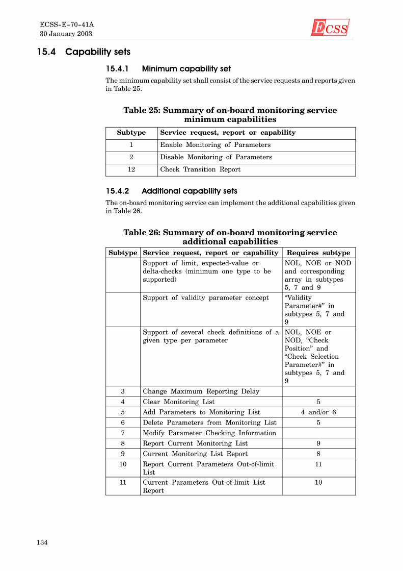
ECSS30 January 2003ECSS--E--70--41A
134
15.4 Capability sets
15.4.1 Minimum capability setTheminimum capability set shall consist of the service requests and reports givenin Table 25.
Table 25: Summary of on-board monitoring serviceminimum capabilities
Subtype Service request, report or capability
1 Enable Monitoring of Parameters
2 Disable Monitoring of Parameters
12 Check Transition Report
15.4.2 Additional capability setsThe on-board monitoring service can implement the additional capabilities givenin Table 26.
Table 26: Summary of on-board monitoring serviceadditional capabilities
Subtype Service request, report or capability Requires subtype
Support of limit, expected-value ordelta-checks (minimum one type to besupported)
NOL, NOE or NODand correspondingarray in subtypes5, 7 and 9
Support of validity parameter concept “ValidityParameter#” insubtypes 5, 7 and9
Support of several check definitions of agiven type per parameter
NOL, NOE orNOD, “CheckPosition” and“Check SelectionParameter#” insubtypes 5, 7 and9
3 Change Maximum Reporting Delay
4 Clear Monitoring List 5
5 Add Parameters to Monitoring List 4 and/or 6
6 Delete Parameters from Monitoring List 5
7 Modify Parameter Checking Information
8 Report Current Monitoring List 9
9 Current Monitoring List Report 8
10 Report Current Parameters Out-of-limitList
11
11 Current Parameters Out-of-limit ListReport
10

ECSS 30 January 2003
ECSS--E--70--41A
135
16
Large data transfer service
16.1 ScopeThe large data transfer service is a supporting service used by the ground systemor other services to transfer large service data units in a controlled manner. Thechoice to use the large data transfer service is made by the initiator of a givenservice data unit.
Some scenarios in which the large data transfer service can be used include:
D the on-board operations scheduling service is requested to report to theground the current contents of the command schedule, whose size exceeds themaximum size of a single telemetry source packet;
D a very large area of on-board memory is loaded using telecommand packetswith a mission-specific maximum size.
The large data transfer service provides a common transfer mechanism for allservices and avoids the proliferation of service-specific solutions. A service dataunit is passed to the large data transfer service which splits it into parts andtransmits each part within a single telemetry source packet (on-board to ground)or a single telecommand packet (ground to on-board).
Different operational requirements can apply to the data transfer, including:
a. the capability to determine when the transfer is complete;
b. the capability to identify and selectively re-transmit those parts of the datawhich are lost during a transfer;
c. the capability to pass the data parts in order, and without duplication, to therecipient.
This service satisfies the concepts described in subclause of this Standard.
Any number of application processes may provide a single instance of the largedata transfer service.
Telemetry source packet and telecommand packet relating to the large datatransfer service shall be denoted by Service Type = 13.

ECSS30 January 2003ECSS--E--70--41A
136
16.2 Service concept
16.2.1 IntroductionThe large data transfer service shall provide two distinct but symmetricaloperations: a large data downlink and a large data uplink.
There are similarities between the two operations; the transfer of a large dataunitimplies the simultaneous use of a sending sub-service on-board and of a receivingsub-service on the ground or vice-versa. However, the emphasis of the servicespecification in this Standard is on the sub-service to be provided on-board.
In the remainder of this subclause, the text relates to thedownlinkof a servicedataunit and the text specific to the uplink case is put in parentheses.
The basic concept for the large data downlink (large data uplink) protocol shall beas follows: when a service data unit or portion of it is passed to the sendingsub-service provider of the large data transfer service, it shall perform thedownlink (uplink) in the following manner:
a. It shall split the original Service Data Unit (SDU) in fixed size parts and sendthe parts one by one, and in order. Each part shall be transmitted within asingle telemetry source packet (telecommand packet) as illustrated inFigure 7.
PH:DFH:CI:
Packet HeaderData Field HeaderTransfer Control Information
SDUHeader
PHDFHCI
Part No 1
Service Data
Original Service Data Unit
Part No 2PHDFHCI
Part No N
Part No 3PHDFHCI
PHDFHCI
Figure 7: The splitting of a service data unit in parts to be downlinked(uplinked)
b. The sending and receiving sub-service providers shall use the same definitionof the size of the parts (Part Size). The parts shall have equal size (exceptpossibly the last part),which shall be less than themaximumsize of the sourcedata field of a telemetry source packet (application data field of atelecommand packet).

ECSS 30 January 2003
ECSS--E--70--41A
137
16.2.2 Service data unit to be downlinked (uplinked)For the large data downlink, the service data unit which an on-board serviceprovider passes to the sending sub-service provider shall consist of either atelemetry source packet or an “extended” telemetry source packet.
For the large data uplink, the service data unit which the ground segment passesto the on-board receiving sub-service provider shall consist of either a telecom-mand packet or an “extended” telecommand packet.
In the remainder of this subclause, depending on the type of transfer, downlink oruplink:
D the term “packet” denotes either a telemetry source packet or a telecommandpacket;
D the term “extended packet” denotes either an “extended” telemetry sourcepacket or an “extended” telecommand packet;
D the term “packet data” denotes the source data or the application data of apacket or extended packet.
The format of any service dataunit to be downlinked (uplinked) shall be as follows:
UnitType
PacketHeader
Data FieldHeader Packet Data
Enumerated 6 octets Deduced Any
Unit Type:
This parameter indicates whether what follows is a standard packet(value = 0) or an extended packet (value = 1).
An extended packet shall have the same structure as a packet, but the sizeof its packet data field can exceed the maximum size defined for a packet(i.e. if the total length of the packet data plus the data field header exceeds65535 octets).
For an extended packet, the value of the packet length field in the packetheader shall be 0.
Packet Header:
This is a standard packet header, but the interpretation of the packetlength field value shall differ for an extended packet (see above).
Data Field Header:
This is a data field header as defined in this Standard for a telemetrysource packet or a telecommand packet.
Packet Data:
This is the source data of a large service report or the application data ofa large service request.
In addition, the sending sub-service provider shall manage a “Large Data UnitID”, which unambiguously identifies the service data unit to be transferred. ThisLarge Data Unit ID is used by the sub-service providers of the large data transferservice on-board and on the ground, to distinguish the parts of this service dataunit from the parts of other service data units for the case where there aresimultaneous, overlapping, large data transfers originating from, or received by,the same on-board application process.
The detailed specification of themechanism used to pass large data units betweenan on-board service provider and a large data transfer service provider is beyondthe scope of this Standard. However, depending on the storage capacity available

ECSS30 January 2003ECSS--E--70--41A
138
to the large data transfer service provider or on design constraints, the followingapproaches can be used.
a. For a downlink operation, the data may be passed by the sending serviceprovider to the on-board large data transfer service provider either as acomplete service data unit or as a set of data blocks (in which case the largedata transfer service provider informs the sending service provider when thenext block may be passed or when a downlink problem occurs). The servicedataunit can even be available in a storage ormemoryarea directly accessibleby the large data transfer service provider.
b. For an uplink operation, the data received by the on-board large data transferservice provider may be passed to the destination service provider either asa complete data unit or as a set of data blocks or it can even be written directlyinto a storage or memory area accessible by the destination service provider.
16.2.3 Large data downlink (uplink) protocolThe following downlink (uplink) protocol aspects complement the basic protocolconcept defined in subclause 16.2.1.
a. The sending sub-service provider can have an attribute (window size)defining the number of parts which may be downlinked prior to receiving anacknowledgement from the receiving sub-service provider.
If this attribute is defined, then at no time should the sequence number of thenext part to be downlinked (uplinked) exceed the sequence number of the lastdownlinked part which has been successfully acknowledged by the receivingsub-service provider bymore than the value of “WindowSize”. In otherwords,a partmay only be sent if it falls within the sliding window defined by the lastacknowledged part and the window size.
Several window sizes can be used by a given large data transfer serviceprovider.
EXAMPLE A large window size can be used for the memory manage-ment service and a smaller window size for other services.
If a sliding window is not used, then the sending sub-service provider shallsend the parts of the service data unit at the highest frequency supportedunder the prevailing operational constraints.
b. When a receiving sub-service provider receives an error-free part, this shallbecome the “last successfully received part” if there is no discontinuitybetween this part and the previous “last successfully received part”.
If a sliding window is used, then no later than when the sequence counter ofthe last received part reaches the boundary of the sliding downlink windowshall the receiving end send a notification of the “last successfully receivedpart”. This enables the sending sub-service provider to slide the downlinkwindow.
If a sliding window is not used, the notification of successful reception shallonly be provided on completion of the service data unit reception.
In both situations, this ensures that the sending sub-service provider caninform the originating service provider (the ground system) of the success orfailure of the downlink (uplink). Onlywhen the destination application on theground (destination service provider on-board) has received the completeservice data unit should notification of successful reception of the final partbe uplinked (downlinked) by the receiving end of the large data transferservice.
c. When the sending sub-service provider has sent the last part which can besent in the current sliding window or the last part of the service data unit, itshall initiate an “acknowledgement timer”. If it does not receive a notificationof “last successfully received part” or an abort notification within a specified

ECSS 30 January 2003
ECSS--E--70--41A
139
timeout interval, then it shall assume that the downlink (uplink) has failedand shall notify the originating service provider (the ground system)accordingly.
d. When the first, or an intermediate, part (which can be a re-transmitted part)is received by a receiving sub-service provider, a “reception timer” shall beinitiated. If the receiving sub-service provider does not receive a subsequentpart within a specified timeout interval, then it shall assume that thedownlink (uplink) has failed and the reception activity shall be locallyaborted. The destination application on the ground (destination serviceprovider on-board) shall be notified accordingly.
e. If the receiving sub-service provider receives an erroneous part or detects agap in the reception sequence it shall add the erroneous or missing part(s) tothe set of “failed parts”. Depending on the implementation, this informationmay be used by the receiving sub-service provider to automatically requestthe re-transmission of these parts or simply to inform the ground system (thedestination service provider) of the errors in the transferred data.
f. If a sliding window is used, then no later than when the sequence counter ofthe last received part reaches the boundary of the sliding window shall thereceiving sub-service provider send notifications of the failed parts.
The sending sub-service provider shall then re-transmit (though notnecessarily immediately) the notified failed parts. The successful re-trans-mission of a failed part shall update the set of failed parts and can determinea new “last successfully received part”.
If a sliding window is not used, notification of failed parts is unnecessary.However, if the receiving sub-service provider does send such a notification,then the sending sub-service provider shall re-transmit the failed parts.
g. At any time during the downlink (uplink) activity, the originating (destina-tion) service provider or the ground segment can abort the large data transferoperation.
If the sending sub-service provider can perform several overlapping datatransfers, there shall be no restriction on the order in which it sends or re-sendsthe parts of the different data transfers other than the restrictions defined above.
16.3 Service requests and reports
16.3.1 IntroductionFor each data downlink service request, there is a corresponding data uplinkservice report with an identical structure. For each data downlink service report,there is a corresponding data uplink service request with an identical structure.
16.3.2 Transferring the first part of a service data unitThe report to downlink and the request to uplink the first part of a large servicedata unit shall be:
First Downlink Part Report (13,1)
Telemetry source packet, source data:
Accept First Uplink Part (13,9)
Telecommand packet, application data:
Large DataUnit ID
Sequence Number Service Data Unit Part
Enumerated Unsigned Integer Fixed OctetString
Optional

ECSS30 January 2003ECSS--E--70--41A
140
Large Data Unit ID:
This uniquely identifies the service data unit which is the subject of thetransfer.
This field shall be systematically omitted if the service provider only sup-ports the downlink (or uplink) of one service data unit at a time. Thisapplies to all requests and reports in this subclause.
Sequence Number:
This is a unique identification for this part of the service data unit. By con-vention, the sequence number of the first part shall be 1. The sequencenumber shall then be incremented by one for each part which is subse-quently transferred.
Service Data Unit Part:
This is the first part of the service data unit. Its size shall always be equalto the part size in use.
Downlink: The on-board sending sub-service provider shall use this report to sendthe first part of the data to be downlinked.
Uplink: The ground segment shall use this request to send the first part of the datato be uplinked.
On reception of the part, the receiving sub-service provider shall update its contextand initiate a reception timer.
16.3.3 Transferring an intermediate part of a service data unitThe report to downlink and the request to uplink an intermediate part of a largeservice data unit shall be:
Intermediate Downlink Part Report (13,2)
Telemetry source packet, source data:
Accept Intermediate Uplink Part (13,10)
Telecommand packet, application data:
Same as for (13,1) and (13,9).
The size of an intermediate part of the service data unit shall always be equal tothe part size in use.
Downlink: The sending sub-service provider shall use this report to send anintermediate part of the data to be downlinked.
Uplink: The ground segment shall use this request to send an intermediate partof the data to be uplinked.
The sending sub-service provider shall initiate an acknowledgement timer if thispart is the last part which can be sent in the current sliding window.
On reception of the part, the receiving sub-service provider shall update its contextand initiate a reception timer.
16.3.4 Transferring the last part of a service data unitThe report to downlink and the request to uplink the last part of a large servicedata unit shall be:
Last Downlink Part Report (13,3)
Telemetry source packet, source data:
Accept Last Uplink Part (13,11)
Telecommand packet, application data:
Same as for (13,1) and (13,9).

ECSS 30 January 2003
ECSS--E--70--41A
141
The size of the last part of a service data unit shall be less than or equal to the partsize in use.
Downlink: The sending sub-service provider shall use this report to send the lastpart of the data to be downlinked.
Uplink: The ground segment shall use this request to send the last part of the datato be uplinked.
The sending sub-service provider shall always initiate anacknowledgement timer.
On reception of the part, the receiving sub-service provider shall update its contextand immediately notify the sending sub-service provider of what is the “lastsuccessfully received part” at this point.
16.3.5 Re-transferring a part of a service data unitThe report to re-downlinkand the request to re-uplinkapart of a large service dataunit whose re-transmission has been requested by the receiving end shall be:
Repeated Part Report (13,7)
Telemetry source packet, source data:
Accept Repeated Part (13,12)
Telecommand packet, application data:
Same as for (13,1) and (13,9).
The sequence number shall be the same as the sequence number used for theinitial transfer.
Downlink: The sending sub-service provider shall use this report to re-transmita part of the datawhichwasnot properly received by the ground systemandwhichwas requested for re-transmission.
Uplink:The ground segment shall use this request to re-transmit a part of the datawhich was not properly received by the on-board receiving sub-service provider.
The sending sub-service provider shall initiate an acknowledgement timer if thispart is the last part which can be sent in the current window.
On reception of the part, the receiving sub-service provider shall update its contextand initiate a reception timer.
16.3.6 Transfer abort initiated by the sending endThe report (during a downlink operation) and the request (during an uplinkoperation) to notify a transfer abort initiated by the sending end shall be:
Downlink Abort Report (13,4)
Telemetry source packet, source data:
Abort Reception of Uplinked Data (13,13)
Telecommand packet, application data:
Large Data Unit ID Reason Code
Enumerated Enumerated
Optional Optional
Reason Code:
This indicates the reason for the transfer abort. The values itmay take aremission-specific.
Downlink: The sending sub-service provider shall use this report to indicate to theground system that the large data downlink operation has been aborted (e.g. bythe originating service provider).

ECSS30 January 2003ECSS--E--70--41A
142
Uplink: The ground segment shall use this request to indicate to the on-boardreceiving sub-service provider that the large data reception activities should beaborted. The on-board receiving sub-service provider shall inform the destinationservice provider of the abort.
16.3.7 Acknowledging the successful reception up to a partThe report (during an uplink operation) and the request (during a downlinkoperation) to acknowledge the successful reception of the large service data unitup to a specified part shall be:
Uplink Reception Acknowledgement Report (13,14)
Telemetry source packet, source data:
Downlink Reception Acknowledgement (13,5)
Telecommand packet, application data:
Large Data Unit ID Sequence Number
Enumerated Unsigned Integer
Optional
The receiving sub-service provider shall use this notification to indicate to thesending sub-service provider that it has successfully received all parts of the largeservice dataunit up to and including the partwith the indicated sequence number.
If a sliding window is used, this enables it to be moved forward and the sendingactivity to be resumed.
16.3.8 Notifying which parts have not been properly receivedThe report (during an uplink operation) and the request (during a downlinkoperation) to notify the sending sub-service provider that specified parts were notreceived or were erroneously received shall be:
Unsuccessfully Received Parts Report (13,15)
Telemetry source packet, source data:
Repeat Parts (13,6)
Telecommand packet, application data:
Large Data Unit ID N Sequence Number
Enumerated Unsigned Integer Unsigned Integer
Optional Repeated N times
On reception of this notification, the sending sub-service provider shall record theinformation. It shall use this information to re-transmit the parts if a slidingwindow is used or if it is an on-board sending sub-service provider. A groundsystem sending sub-service provider may decide not to re-transmit the parts if asliding window is not used.
16.3.9 Transfer abort initiated by the receiving endThe report (during an uplink operation) and the request (during a downlinkoperation) shall be:
Reception Abort Report (13,16)
Telemetry source packet, source data:
Abort Downlink (13,8)
Telecommand packet, application data:

ECSS 30 January 2003
ECSS--E--70--41A
143
Large Data Unit ID Reason Code
Enumerated Enumerated
Optional Optional
Reason Code:
This indicates the reason for the transfer abort. The values itmay take aremission-specific.
On reception of this notification, the sending sub-service provider shall inform theoriginating service provider (the ground system) that the downlink (uplink)operation shall be aborted.
16.4 Capability sets
16.4.1 Minimum capability setsEach sub-service (sending and receiving) is optional, but a given implementationof the large data transfer service shall support at least one sub-service.
Theminimumcapability set for the sending sub-service (data downlink operation)shall consist of the service requests and reports given in Table 27.
Table 27: Summary of sending sub-service (downlink)minimum capabilities
Subtype Service request, report or capability
1 First Downlink Part Report
2 Intermediate Downlink Part Report
3 Last Downlink Part Report
4 Downlink Abort Report
5 Downlink Reception Acknowledgement
8 Abort Downlink
The minimum capability set for the receiving sub-service (data uplink operation)shall consist of the service requests and reports given in Table 28.
Table 28: Summary of receiving sub-service (uplink)minimum capabilities
Subtype Service request, report or capability
9 Accept First Uplink Part
10 Accept Intermediate Uplink Part
11 Accept Last Uplink Part
13 Abort Reception of Uplinked Data
14 Uplink Reception Acknowledgement Report
16 Reception Abort Report

ECSS30 January 2003ECSS--E--70--41A
144
16.4.2 Additional capability setsThe use of a “Sliding Window” and the automatic re-transmission of lost orerroneous parts are optional.
The selective re-transmission of lost or erroneous parts without using a slidingwindow is optional.
The sending sub-service provider (data downlink operation) can implement theadditional capabilities given in Table 29.
Table 29: Summary of sending sub-service (downlink)additional capabilities
Subtype Service request, report or capabilityRequiressubtype
6 Repeat Parts 7
7 Repeated Part Report 6
Use of a “Sliding Window” 7 and 6
The receiving sub-service provider (data uplink operation) can implement theadditional capabilities given in Table 30.
Table 30: Summary of receiving sub-service (uplink)additional capabilities
Subtype Service request, report or capabilityRequiressubtype
12 Accept Repeated Part 15
15 Unsuccessfully Received Parts Report 12
Use of a “Sliding Window” 12 and 15

ECSS 30 January 2003
ECSS--E--70--41A
145
17
Packet forwarding control service
17.1 ScopeThe packet forwarding control service provides the capability to control theforwarding to the ground of telemetry source packets issued by on-board services.
This service satisfies the packet forwarding concepts described in subclause 4.12of this Standard.
Anynumber of on-board application processesmay provide a single instance of thepacket forwarding control service.
Telemetry source packets and telecommand packets relating to the packetforwarding control service shall be denoted by Service Type = 14.
17.2 Service conceptTwo options exist for the location of this service, either it may be provided at thelevel of the originating application process or it may be provided by a centralisedapplication process which is responsible for routing packets on the downlink.
The packet forwarding control service shall maintain the knowledge of whichpackets can be transmitted to the ground system.
For a given application process, the forwarding of packets can be “enabled” and“disabled” at the level of:
a. a type of packet;
b. a subtype of packet;
c. a housekeeping packet definition, a diagnostic packet definition or an eventreport definition (see clauses 8 and 10).
The forwarding of packets with a given type and subtype shall be “enabled” if andonly if the packet type and the packet subtype are both enabled (i.e. if the type isin the set of enabled types and the subtype is in the set of enabled subtypes for thattype).
In addition, the forwarding of housekeeping (or diagnostic or event report) packetsshall be “enabled” if and only if the packet type, the packet subtype and thehousekeeping packet definition (or the diagnostic packet definition or the eventreport definition) are all enabled.
Conceptually, this is as if each such packet definition has three independentcontrolling attributes (at type level, at subtype level and at packet structure

ECSS30 January 2003ECSS--E--70--41A
146
identification level) whose values determine the forwarding status of the packetsin accordance with Table 31.
Table 31: Decision table for the forwarding status of apacket
Type SubtypeIdentification(SID/RID)
Forwardingstatus
D(isabled) E(nabled) E D
D D E D
D E D D
D D D D
E E E E
E D E D
E E D D
E D D D
The packet forwarding control service shall maintain the forwarding status for alltypes and subtypes of packet (per application process, in the case of the centralisedoption) and shall report the list of enabled packets to the ground system onrequest.
Similarly, the packet forwarding control service shall maintain the forwardingstatus for all housekeeping packet definitions, diagnostic packet definitions andevent report definitions (per application process, in the case of the centralisedoption) and shall report the list of enabled packets to the ground system onrequest.
17.3 Service requests and reports
17.3.1 Controlling the forwarding of specified telemetry sourcepackets
The requests to enable or disable the forwarding of telemetry source packets ofspecified type and subtype shall be:
Enable Forwarding of Telemetry Source Packets (14,1)
Telecommand packet, application data:
Disable Forwarding of Telemetry Source Packets (14,2)
Telecommand packet, application data:
N1 ApplicationProcess ID
N2 Type N3 Subtype
UnsignedInteger
Enumerated UnsignedInteger
Enumerated UnsignedInteger
Enumerated
Optional Repeated N3 timesRepeated N2 times
Repeated N1 times
N1:
The number of application processes that follow.
This field shall be systematically omitted if the packet forwarding serviceis provided by the originating application process.

ECSS 30 January 2003
ECSS--E--70--41A
147
Application Process ID:
The identification of the originating application process of the packets tobe forwarded.
This field shall be systematically omitted if the packet forwarding serviceis provided by the originating application process.
Type:
The telemetry source packet service type.
Subtype:
The telemetry source packet service subtype for the specified service type.
When the service provider receives this request one of the following shall occur:
a. If N2 = 0 and “enable” is requested, all types of telemetry source packets fromthe corresponding application process shall be placed in the set of enabledtypes.
b. If N2 = 0 and “disable” is requested, all types of telemetry source packets fromthe corresponding application process shall be removed from the set ofenabled types and all sets of enabled subtypes shall be cleared.
c. If N2 > 0 andN3= 0 and “enable” is requested, the specified types of telemetrysource packets from the corresponding application process shall be added tothe set of enabled types.
d. IfN2>0andN3=0and “disable” is requested, the specified types of telemetrysource packets from the corresponding application process shall be removedfrom the set of enabled types and their sets of enabled subtypes shall becleared.
e. If N2 > 0 and N3 > 0 and “enable” is requested, the specified subtypes oftelemetry source packets from the corresponding application process shall beadded to the set of enabled subtypes for the specified type.
f. If N2 > 0 and N3 > 0 and “disable” is requested, the specified subtypes oftelemetry source packets from the corresponding application process shall beremoved from the set of enabled subtypes for the specified type.
NOTE 1 If N2 > 1 then there can be a mixture of empty (N3 = 0) andnon-empty (N3 > 0) arrays.
NOTE 2 These requests do not change the forwarding status at thelevel of the SID/RID.
An error shall be flagged if a specified type or subtype of packet is not generatedby the corresponding application process. However, the processing of the othertypes and subtypes in the request shall be unaffected.
17.3.2 Reporting the list of enabled telemetry source packetsThe request to report the list of telemetry source packet types and subtypes withan “enabled” forwarding status shall be:
Report Enabled Telemetry Source Packets (14,3)
Telecommand packet, application data: None
When this request is received, the enabled types and subtypes of telemetry sourcepacket shall be determined and a report shall be generated.

ECSS30 January 2003ECSS--E--70--41A
148
Enabled Telemetry Source Packets Report (14,4)
Telemetry source packet, source data:
N1 ApplicationProcess ID
N2 Type N3 Subtype
UnsignedInteger
Enumerated UnsignedInteger
Enumerated UnsignedInteger
Enumerated
Optional Repeated N3 timesRepeated N2 times
Repeated N1 times
IfN2=0, no type nor subtype of packet from the corresponding application processis enabled.
If N2 > 0, the specified types of packet from the corresponding application processare enabled.
If N3 = 0 for a type of packet, none of the subtypes of this type from thecorresponding application process are enabled.
If N3 > 0 for a type of packet, the specified subtypes of this type from thecorresponding application process are enabled.
NOTE If N2 > 1 then there can be a mixture of empty (N3 = 0) andnon-empty (N3 > 0) arrays.
17.3.3 Controlling the forwarding of specified housekeepingpackets
The requests shall be:
Enable Forwarding of Housekeeping Packets (14,5)
Telecommand packet, application data:
Disable Forwarding of Housekeeping Packets (14,6)
Telecommand packet, application data:
N1 ApplicationProcess ID
N2 SID
UnsignedInteger
Enumerated UnsignedInteger
Enumerated
Optional Optional Repeated N2 timesOptional
Repeated N1 times
N2:
The number of housekeeping packet definitions to be enabled or disabled.
N1 andN2 shall be systematically omitted if the service only supports thecontrol of one housekeeping packet at a time.
SID:
The Structure Identifier identifying a housekeeping packet definition.
When this request is received, the specified housekeeping packet definitions fromthe corresponding application process shall be added to (or removed from) the setof enabled housekeeping packet definitions (depending on whether it is an“enable” or “disable” request).
An error shall be flagged if a specified housekeeping SID is not defined for theapplication process. However, this shall not affect the processing of the otherhousekeeping SIDs in the request.

ECSS 30 January 2003
ECSS--E--70--41A
149
17.3.4 Reporting the list of enabled housekeeping packetsThe request to report the list of housekeeping packet definitionswith an “enabled”forwarding status shall be:
Report Enabled Housekeeping Packets (14,7)
Telecommand packet, application data: None.
When this request is received, the list of enabled housekeeping packet definitionsshall be determined and a report shall be generated.
Enabled Housekeeping Packets Report (14,8)
Telemetry source packet, source data:
N1 ApplicationProcess ID
N2 SID
UnsignedInteger
Enumerated UnsignedInteger
Enumerated
Optional Repeated N2 timesRepeated N1 times
17.3.5 Controlling the forwarding of specified diagnosticpackets
The requests shall be:
Enable Forwarding of Diagnostic Packets (14,9)
Telecommand packet, application data:
Disable Forwarding of Diagnostic Packets (14,10)
Telecommand packet, application data:
N1 ApplicationProcess ID
N2 SID
UnsignedInteger
Enumerated UnsignedInteger
Enumerated
Optional Optional Repeated N2 timesOptional
Repeated N1 times
N2:
The number of diagnostic packet definitions to be enabled or disabled.
N1 andN2 shall be systematically omitted if the service only supports thecontrol of one diagnostic packet at a time.
SID:
The Structure Identifier identifying a diagnostic packet definition.
When this request is received, the specified diagnostic packet definitions from thecorresponding application process shall be added to (or removed from) the set ofenabled diagnostic packet definitions (depending on whether it is an “enable” or“disable” request).
An error shall be flagged if a specified diagnostic SID is not defined for theapplication process,. However, this shall not affect the processing of the otherdiagnostic SIDs in the request.

ECSS30 January 2003ECSS--E--70--41A
150
17.3.6 Reporting the list of enabled diagnostic packetsThe request to report the list of diagnostic packet definitions with an “enabled”forwarding status shall be:
Report Enabled Diagnostic Packets (14,11)
Telecommand packet, application data: None.
When this request is received, the list of enabled diagnostic packet definitionsshall be determined and a report shall be generated.
Enabled Diagnostic Packets Report (14,12)
Telemetry source packet, source data:
N1 ApplicationProcess ID
N2 SID
UnsignedInteger
Enumerated UnsignedInteger
Enumerated
Optional Repeated N2 timesRepeated N1 times
17.3.7 Controlling the forwarding of specified event reportpackets
The requests to enable or disable the forwarding of specified event report packetsshall be:
Enable Forwarding of Event Report Packets (14,13)
Telecommand packet, application data:
Disable Forwarding of Event Report Packets (14,14)
Telecommand packet, application data:
N1 ApplicationProcess ID
N2 RID
UnsignedInteger
Enumerated UnsignedInteger
Enumerated
Optional Optional Repeated N2 timesOptional
Repeated N1 times
N2:
The number of event report packet definitions to be enabled or disabled.
N1 andN2 shall be systematically omitted if the service only supports thecontrol of one event report packet at a time.
RID:
The report identifier identifying an event report packet definition.
When this request is received, the specified event report packet definitions fromthe corresponding application process shall be added to (or removed from) the setof enabled event report packet definitions (depending on whether it is an “enable”or “disable” request).
An error shall be flagged if a specified event RID is not defined for the applicationprocess.However, this shall not affect the processing of the other eventRIDs in therequest.

ECSS 30 January 2003
ECSS--E--70--41A
151
17.3.8 Reporting the list of enabled event report packetsThe request to report the list of event report packet definitions with an “enabled”forwarding status shall be:
Report Enabled Event Report Packets (14,15)
Telecommand packet, application data: None
When this request is received, the list of enabled event report packet definitionsshall be determined and a report shall be generated.
Enabled Event Report Packets Report (14,16)
Telemetry source packet, source data:
N1 ApplicationProcess ID
N2 RID
UnsignedInteger
Enumerated UnsignedInteger
Enumerated
Optional Repeated N2 timesRepeated N1 times
17.4 Capability sets
17.4.1 Minimum capability setThe capability to control the forwarding of a given type of definition of a statusreporting packet (i.e. a housekeeping, diagnostic or event report packet) shall onlybe provided if the corresponding type of definition is generated.
Thus, the minimum capability set shall consist of the service requests and reportsgiven in Table 32.
Table 32: Summary of packet forwarding control serviceminimum capabilities
Subtype Service request, report or capability
1 Enable Forwarding of Telemetry Source Packets
2 Disable Forwarding of Telemetry Source Packets

ECSS30 January 2003ECSS--E--70--41A
152
17.4.2 Additional capability setsA packet forwarding control service can implement the additional capabilitiesgiven in Table 33.
Table 33: Summary of packet forwarding control serviceadditional capabilities
Subtype Service request, report or capabilityRequiressubtype
3 Report Enabled Telemetry Source Packets 4
4 Enabled Telemetry Source Packets Report 3
5 Enable Forwarding of Housekeeping Packets 6
6 Disable Forwarding of Housekeeping Packets 5
7 Report Enabled Housekeeping Packets 8, 5 and 6
8 Enabled Housekeeping Packets Report 7
9 Enable Forwarding of Diagnostic Packets 10
10 Disable Forwarding of Diagnostic Packets 9
11 Report Enabled Diagnostic Packets 12, 9 and 10
12 Enabled Diagnostic Packets Report 11
13 Enable Forwarding of Event Report Packets 14
14 Disable Forwarding of Event Report Packets 13
15 Report Enabled Event Report Packets 16, 13 and 14
16 Enabled Report Event Packets Report 15

ECSS 30 January 2003
ECSS--E--70--41A
153
18
On-board storage and retrieval service
18.1 ScopeThe on-board storage and retrieval service is a supporting service used by otheron-board services to selectively store the service reports which they generate inorder to give the ground system the capability to request the retrieval anddownlink of the selectively stored data.
The on-board storage and retrieval service consists of two parts:
a. a packet selection sub-service: selection and transfer of telemetry sourcepackets for storage in packet stores;
b. a storage and retrieval sub-service: storage and retrieval of telemetry sourcepackets from packet stores.
This service satisfies the concepts described in subclause 4.11 of this Standard.
Anynumber of on-board application processesmay provide a single instance of theon-board storage and retrieval service.
Telemetry source packets and telecommand packets relating to the on-boardstorage and retrieval service shall be denoted by Service Type = 15.
18.2 Service concept
18.2.1 GeneralThe on-board storage and retrieval service shall be used if amission uses on-boardstorage of telemetry source packets with the capability to selectively store thepacket types and subtypes in different packet stores.
EXAMPLE For missions with intermittent coverage, packets of highoperational significance (anomaly report packets) which aregenerated during a period of non-coverage can be stored ina dedicated packet store so that they can be retrieved firstduring the next period of coverage.
The service can also be used by application processes to provide a “lost packetrecovery” capability, protecting against temporary spacelink outages, by system-atically placing event-driven service reports in short-term circular packet stores.
One or more packet types and subtypes generated by one or more applicationprocesses can be selected for storage in a given packet store managed by a givenapplication process.

ECSS30 January 2003ECSS--E--70--41A
154
The application process that selects which telemetry source packets are sent forstorage, either to another application process or to its own storage and retrievalsub-service, shall provide the packet selection sub-service.
The application process responsible formanaging the packet store(s) shall providethe storage and retrieval sub-service.
The service concept includes the possibility that the packet selection sub-serviceis always provided by the same application process that provides the storage andretrieval sub-service (rather than by the application process that generates thepackets). This leads to an implementation where all selection, storage andretrieval is performed by a centralised application process that (by design) hasaccess to all telemetry packets.
A packet store is uniquely identified by a “Store ID”. The packet selectionsub-service shall know implicitly (e.g. by virtue of its design) which applicationprocess provides the storage and retrieval sub-service thatmanages a packet storeto which it transfers packets.
The definition of the storage selection used by a given packet selection sub-servicecan either be predefined or changeable by the ground system.
Packets shall be ordered according to their time of arrival at the storage andretrieval sub-service.
Telemetry source packets stored in a packet store shall be downlinked on request.The downlink request may specify that all, or a subset (e.g. within a specifiedpacket range), of the stored packets are downlinked.
Two options exist for downlinking stored telemetry source packets:
a. They can be downlinked in the same virtual channel as real-time data, inwhich case, they shall be wrapped in a “real-time” packet envelope, where theenvelope bears the service type and subtype of the on-board storage andretrieval service.
b. They can be downlinked in a virtual channel that is dedicated to retrieval, inwhich case they shall be downlinked exactly as originally received by thepacket store.
Only one of these options shall exist (by design) for a given storage and retrievalservice.

ECSS 30 January 2003
ECSS--E--70--41A
155
Enable Storage, Disable Storage,Change Storage Definition
E, F
Downlink
A, B, C
Application Process 1
Packet Selection Sub-Service
Storage SelectionPackets A, B & C toPS1Packet D to PS2 Application Process 3
Storage and RetrievalSub-Service
PS1
PS2D
Downlink Contents,Delete Contents
Application Process 2
Packet Selection Sub-Service
Storage SelectionPackets E & F to PS2
Figure 8: An example of a storage and retrieval approach
The storage and retrieval sub-service can (optionally) time stamp each telemetrysource packet it receives with the time of reception/storage. Where this service isoffered, the ground system can request the downlink of packets fromapacket storewhich were stored after, before, or between specified times.
When downlinking using the real-time virtual channel, the packet storage andretrieval sub-service may use the large data transfer service to downlink therequested packets. The service data unit containing the data to be downlinkedshall be constructed by retrieving from the packet store those packets whichmeetthe selection criteria specified by the ground system. The position within theservice data unit shall correspond to the packet store reception and storage order.
The specification of the mechanism by which a given storage and retrievalsub-service receives packets to be stored from the services of application processesis beyond the scope of this Standard.
18.2.2 Packet store typesEach packet store has attributes, which are accessed by the storage and retrievalsub-service which manages it, and which shall indicate:
a. whether the storage strategy is circular or bounded;
b. the maximum size of the packet store;
c. the boundaries of the current set of stored packets (e.g. the oldest and newestpackets).

ECSS30 January 2003ECSS--E--70--41A
156
When a circular packet store is full, any subsequently received packet shalloverwrite partly or fully the oldest packet(s) in the list. A packet store used toprovide a “lost packet recovery” capability shall be circular in nature.
When a bounded packet store is full, any subsequently received packet shall beignored. The contents of the packet store, or at least the oldest part of it, shall beexplicitly deleted in order to free storage space and to enable the resumption ofstorage of new packets. This type of deletion (i.e. erasing the contents of a packetstore) can also be performed on a circular packet store.
The performance of a storage and retrieval sub-service may not be able toguarantee storage of packets without loss.Moreover, the protocol used for passingpackets to the storage and retrieval sub-service is not always reliable. If packetscannot be stored, the service need not record information about the gaps in thesequence of stored packets. These gaps can be detected on the ground following thedownlink of the contents of a packet store.
When the contents of a circular packet store are being downlinked, the storage andretrieval sub-service may not be able to guarantee that packets are downlinked ata higher rate than that at which new packets are arriving at the packet store. Inthis case, priority shall be given to the downlink activity, i.e. the overwritingpointer shall always stay behind the retrieval pointer. In otherwords, newpacketsshall not be placed in the packet store until the packets being retrieved have beendownlinked.
Such a strategy is appropriate where the spacelink is being used to downlink bothreal-time packets and packets retrieved from the packet store. The newest packetsshall be received directly by the ground system, whilst the oldest packets in thepacket store shall not be overwritten until downlinked.
In addition tohousekeeping data that canbe reported on a regular basis, catalogueinformation should bemaintainedby the storage and retrieval sub-service for eachpacket store, which shall be reported to ground on request. This catalogueinformation shall include: identification of the oldest and newest packets in thepacket store, the percentage of filling of the packet store, the percentage of thepacket store contents that has not yet been downlinked.
18.3 Service requests and reports
18.3.1 Controlling the storage in specified packet storesThe requests shall be:
Enable Storage in Packet Stores (15,1)
Telecommand packet, application data:
Disable Storage in Packet Stores (15,2)
Telecommand packet, application data:
N Store ID
Unsigned Integer Fixed CharString
Optional Repeated N times
N:
The number of packet stores to be controlled. By convention, N = 0 shallmean “all packet stores”.
This field shall be systematically omitted if the service only supports onepacket store (this is equivalent to having N=0).

ECSS 30 January 2003
ECSS--E--70--41A
157
Store ID:
An on-board packet store is uniquely identified by a “Store ID”. This shallbe a character string which can explicitly or implicitly indicate, forexample, anaccesspath to aphysical on-board recording device or file. Themeaning and internal structure of the Store IDare beyond the scope of thisStandard.
When the packet selection sub-service provider receives this request, it shall startor stop (depending on whether it is an “enable” or “disable” request) sending therelevant packets to the application processes managing the specified packetstores.
18.3.2 Modifying the definition of a storage selection criteriaThe storage selection definition used by an application process to send packets forstorage in a given packet store shall consists of the identification of the type andsubtype of the relevant packets. If the packets originate from an applicationprocess other than that which provides the packet selection sub-service, theoriginating application process shall also be specified. The capability shall exist toadd specified packets to (or remove from) a storage selection definition.
The requests to modify the storage selection definition for a specified packet storeshall be:
Add Packets to Storage Selection Definition (15,3)
Telecommand packet, application data:
Remove Packets from Storage Selection Definition (15,4)
Telecommand packet, application data:
Store ID N1 ApplicationProcess ID
N2 Type N3 Subtype
FixedCharString
UnsignedInteger
Enumerated UnsignedInteger
Enumerated UnsignedInteger
Enumerated
Optional Optional Repeated N3 timesRepeated N2 times
Repeated N1 times
Store ID:
This field shall be systematically omitted if the service only supports onepacket store.
Application Process ID:
The identification of the originating application process of the packets tobe stored.
This field shall be systematically omitted if the packet selection sub-ser-vice is provided by the originating application process.
Type:
A telemetry source packet service type.
Subtype:
A telemetry source packet service subtype of the specified service type.
When the packet selection sub-service provider receives this request one of thefollowing shall occur:
a. If N2 = 0, all types of telemetry source packet from the correspondingapplication process shall be added to, or removed from, the list of packet typesto be stored in the specified packet store (depending on the type of request).

ECSS30 January 2003ECSS--E--70--41A
158
b. If N2 > 0 and N3 = 0, the specified types of telemetry source packet from thecorresponding application process shall be added to (if not yet present), orremoved from, the list of packet types to be stored in the specified packet store(depending on the type of request).
c. If N2 > 0 and N3 > 0, the specified subtypes of telemetry source packet fromthe corresponding application process shall be added to, or removed from, thelist of packet subtypes (for the specified type) to be stored in the specifiedpacket store (depending on the type of request).
The request shall have no effect for a packet type which is already in the list ofpacket types to be stored in the specified packet store (because all its subtypes arealready selected for storage).
NOTE If N2 > 1 then there can be a mixture of empty (N3 = 0) andnon-empty arrays (N3 > 0).
The current content of the packet store shall not be affected by the request and,if storage is enabled, packets shall start or stop to be appended to the packet storeimmediately after the request is processed.
The creation, deletion or modification of packet stores, together with theirattributes is beyond the scope of this Standard.
18.3.3 Reporting a storage selection definitionThe request shall be:
Report Storage Selection Definition (15,5)
Telecommand packet, application data:
Store ID
Fixed CharString
Optional
Store ID:
This field shall be systematically omitted if the service only supports onepacket store.
When this request is received by the application processwhich provides thepacketselection sub-service, the storage selection definition for the specified packet storeshall be read and a report shall be generated.
NOTE Since the destination application process uses a local storageselection definition for selecting which of its packets to sendto a packet store (which can be managed by anotherapplication process), what is downlinked might only repre-sent a partial definition of the complete storage selection forthe given packet store.
Storage Selection Definition Report (15,6)
Telemetry source packet, source data:
Store ID N1 ApplicationProcess ID
N2 Type N3 Subtype
FixedCharString
UnsignedInteger
Enumerated UnsignedInteger
Enumerated UnsignedInteger
Enumerated
Optional Optional Repeated N3 timesRepeated N2 times
Repeated N1 times

ECSS 30 January 2003
ECSS--E--70--41A
159
The Store ID field shall be systematically omitted if the service provider onlysupports one packet store.
The Application Process ID field shall be systematically omitted if the packetselection sub-service is provided by the originating application process.
IfN2=0, no type nor subtype of packet from the corresponding application processis selected for storage.
If N2 > 0, the specified types of packet from the corresponding application processare selected for storage.
If N3 > 0 for a type of packet, the specified subtypes of this type from thecorresponding application process are selected for storage.
18.3.4 Downlinking the contents of a packet store for aspecified packet range
The request shall be:
Downlink Packet Store Contents for Packet Range (15,7)
Telecommand packet, application data:
Store ID Packet Set ApplicationProcess ID 1
Source SequenceCount 1
ApplicationProcess ID 2
Source SequenceCount 2
FixedCharString
Enumerated Enumerated UnsignedInteger
Enumerated UnsignedInteger
Optional Optional Optional Optional
Store ID:
This field shall be systematically omitted if the service provider only sup-ports one packet store.
Packet Set:
This indicates how the packet range is specified. If Packet Set is “All”(value =0), the full contents of the packet store shall be downlinked, other-wise it is the set of packets received and stored:
(a) between the packets identified by (Application Process ID 1, SourceSequence Count 1) and (Application Process ID 2, Source SequenceCount 2) inclusive, if Packet Set is “Between” (value = 1);
(b) up to and including the packet identified by (Application Process ID1, Source Sequence Count 1), if Packet Set is “Before” (value = 2);
(c) after and including the packet identified by (Application Process ID1, Source Sequence Count 1), if Packet Set is “After” (value = 3).
This field shall be systematically omitted if the service provider only sup-ports one way of specifying the packet range. The service provider mayonly support a subset of the Packet Set values.
Application Process ID 1, Source Sequence Count 1:
Application Process ID 2, Source Sequence Count 2:
The identifications of the packets defining the boundary(ies) of the rangeof packets to be downlinked. These shall be matched with the correspon-ding fields in the data field header of packets in the packet store.
The fields Application Process ID 1 and Source Sequence Count 1 shall bepresent if Packet Set is not “All”. The fields Application Process ID 2 andSource Sequence Count 2 shall be present if Packet Set is “Between”.
When this request is received by the application process which provides thestorage and retrieval sub-service, the contents of the specified packet store fallingwithin the specified packet range shall be downlinked. In this respect, “falling

ECSS30 January 2003ECSS--E--70--41A
160
within” refers to the time interval between the time of reception (by the storageand retrieval sub-service) of the first and last packets defining the packet set.Whatever the value of Packet Set, the retrieval shall end at the latest when thelast packet stored at the time of reception of the request has been downlinked.
If a packet defining a lower boundary of the packet range is not in the packet store,the retrieval shall start with the last packet from the same application processbefore themissing packet (or the oldest stored packet if no earlier packet from thatapplication process is in the packet store).
If a packet defining an upper boundary of the packet range is not in the packetstore, the retrieval shall end with the first packet from the same applicationprocess after the missing packet (or the end of the packet store at the time ofreception of the request).
Depending on the service design, the retrieved packets shall be either:
D downlinked directly into a dedicated virtual channel, i.e. exactly as receivedby the packet store; or
D placed in a report in the same sequence as their storage order and downlinkedin the real-time virtual channel (using the large data transfer service, ifappropriate). The format of this report shall be:
Packet Store Contents Report (15,8)
Telemetry source packet, source data:
N TLM Packet
Unsigned Integer Any TM
Repeated N times
TLM Packet:
A telemetry source packet of any type retrieved from the packet store.
18.3.5 Downlinking the contents of a packet store for aspecified time period
The request shall be:
Downlink Packet Store Contents for Time Period (15,9)
Telecommand packet, application data:
Store ID Time Span Storage Time 1 Storage Time 2
Fixed CharString Enumerated Absolute Time Absolute Time
Optional Optional Optional Optional
Store ID:
This field shall be systematically omitted if the service only supports onepacket store.
Time Span:
This indicates how the packet range is specified. If Time Span is “All”(value =0), the full contents of the packet store shall be downlinked, other-wise it is the set of packets whose storage times are:
(a) between Storage Time 1 and Storage Time 2 inclusive, if Time Spanis Between” (value = 1);
(b) less than or equal to Storage Time 1 if Time Span is “Before”(value = 2);
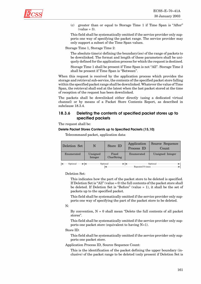
ECSS 30 January 2003
ECSS--E--70--41A
161
(c) greater than or equal to Storage Time 1 if Time Span is “After”(value = 3).
This field shall be systematically omitted if the service provider only sup-ports one way of specifying the packet range. The service provider mayonly support a subset of the Time Span values.
Storage Time 1, Storage Time 2:
The absolute time(s) defining the boundary(ies) of the range of packets tobe downlinked. The format and length of these parameters shall be uni-quely defined for the application process forwhich the request is destined.
Storage Time 1 shall be present if Time Span is not “All”. Storage Time 2shall be present if Time Span is “Between”.
When this request is received by the application process which provides thestorage and retrieval sub-service, the contents of the specified packet store fallingwithin the specified packet range shall be downlinked.Whatever the value ofTimeSpan, the retrieval shall end at the latest when the last packet stored at the timeof reception of the request has been downlinked.
The packets shall be downlinked either directly (using a dedicated virtualchannel) or by means of a Packet Store Contents Report, as described insubclause 18.3.4.
18.3.6 Deleting the contents of specified packet stores up tospecified packets
The request shall be:
Delete Packet Stores Contents up to Specified Packets (15,10)
Telecommand packet, application data:
Deletion Set N Store IDApplicationProcess ID
Source SequenceCount
Enumerated UnsignedInteger
FixedCharString
Enumerated Unsigned Integer
Optional Optional OptionalRepeated N times
Deletion Set:
This indicates how the part of the packet store to be deleted is specified.If Deletion Set is “All” (value = 0) the full contents of the packet store shallbe deleted. If Deletion Set is “Before” (value = 1), it shall be the set ofpackets up to the specified packet.
This field shall be systematically omitted if the service provider only sup-ports one way of specifying the part of the packet store to be deleted.
N:
By convention, N = 0 shall mean “Delete the full contents of all packetstores”.
This field shall be systematically omitted if the service provider only sup-ports one packet store (equivalent to having N=1).
Store ID:
This field shall be systematically omitted if the service provider only sup-ports one packet store.
Application Process ID, Source Sequence Count:
This is the identification of the packet defining the upper boundary (in-clusive) of the packet range to be deleted (only present if Deletion Set is

ECSS30 January 2003ECSS--E--70--41A
162
“Before”). These fields shall be matched with the corresponding fields inthe data field header of packets in the packet store.
When this request is received by the application process which provides thestorage and retrieval sub-service, the packets in the specified packet stores whichhave been stored before the specified packet shall be deleted. The deletion shallend at the latestwhen the last packets stored at the time of reception of the requesthave been deleted. If N = 0, the full contents of all packet stores shall be deleted.
If a packet defining the upper boundary of the packet range is not in the packetstore, the deletion shall endwith the last packet from the same application processbefore themissing packet (or nothing shall be deleted if no earlier packet from thatapplication process is in the packet store).
While deletion from a packet store is in progress, packets sent for storage can berecorded in the freed space of the packet store.
18.3.7 Deleting the contents of specified packet stores up to aspecified storage time
The request shall be:
Delete Packet Stores Contents up to Specified Storage Time (15,11)
Telecommand packet, application data:
End Time N Store ID
Absolute Time Unsigned Integer Fixed CharString
Optional Repeated N times
End Time:
The absolute time defining the upper boundary (inclusive) of the packetrange to be deleted. The format and length of this parameter shall be uni-quely defined for the application process forwhich the request is destined.
N:
By convention, N = 0 shall mean “All packet stores”.
This field shall be systematically omitted if the service provider only sup-ports one packet store (equivalent to having N=0).
When this request is received by the application process which provides thestorage and retrieval sub-service, the packets in the specified packet stores (allpacket stores if N = 0) which have a storage time earlier than or equal to thespecified time shall be deleted. The deletion shall end at the latest when the lastpackets stored at the time of reception of the request have been deleted.
While deletion from a packet store is in progress, packets sent for storage can berecorded in the freed space of the packet store.
18.3.8 Reporting packet store cataloguesThe request to report the catalogues of selected packet stores shall be:
Report Catalogues for Selected Packet Stores (15,12)
Telecommand packet, application data:
N Store ID
Unsigned Integer Fixed CharString
Optional Repeated N times

ECSS 30 January 2003
ECSS--E--70--41A
163
N:
The number of packet stores whose catalogues shall be reported. By con-vention, N = 0 shall mean “all packet stores”.
This field shall be systematically omitted if the service provider only supports onepacket store.
When this request is received by the application process which provides thestorage and retrieval sub-service, the catalogues for the specified packet storesshall be reported. The format of this report shall be:
Packet Store Catalogue Report (15,13)
Telemetry source packet, source data:
N Store IDApplicationProcess ID 1
SourceSequenceCount 1
ServiceType 1
ServiceSubtype 1
PacketSub-
counter 1
StorageTime 1
UnsignedInteger
FixedCharString
Enumerated UnsignedInteger
Enumerated Enumerated UnsignedInteger
AbsoluteTime
Optional Optional OptionalRepeated N times
ApplicationProcess ID 2
SourceSequenceCount 2
ServiceType 2
ServiceSubtype 2
PacketSub--
counter 2
StorageTime 2
Enumerated UnsignedInteger
Enumerated Enumerated UnsignedInteger
AbsoluteTime
Optional OptionalRepeated N times (contd.)
PercentageFilled
PercentageDownlinked
No. ofPacketsStored
No. ofPackets
Downlinked
UnsignedInteger
UnsignedInteger
UnsignedInteger
UnsignedInteger
Repeated N times (contd.)
N, Store ID:
These fields shall be systematically omitted if the service only supportsone packet store.
Application Process ID 1, Source Sequence Count 1, Service Type1, ServiceSubtype1, Packet Sub-counter1:
Application Process ID 2, Source Sequence Count 2, Service Type2, ServiceSubtype2, Packet Sub-counter2:
The corresponding fields from the packet header and data field header ofthe oldest and newest packets respectively within the given packet store.
Storage Time 1, Storage Time 2:
The absolute time of reception of the oldest andnewest packets respective-ly. These fields shall be systematically omitted if the service provider doesnot time-stamp packets on arrival at the packet store.

ECSS30 January 2003ECSS--E--70--41A
164
Percentage Filled:
The percentage of the packet store occupied by stored packets.
Percentage Downlinked:
The percentage of the packet store that has already been downlinked.
No. of Packets Stored:
The total number of packets stored in the packet store.
No. of Packets Downlinked:
The number of packets stored in the packet store that have already beendownlinked.
18.4 Capability sets
18.4.1 Minimum capability setsTheminimumcapability set for the packet selection sub-service shall consist of theservice requests and reports given in Table 34.
Table 34: Summary of packet selection sub-serviceminimum capabilities
Subtype Service request, report or capability
1 Enable Storage in Packet Stores
2 Disable Storage in Packet Stores
Theminimum capability set for the storage and retrieval sub-service shall consistof one of the downlinking options given in Table 35.
Table 35: Summary of storage and retrieval sub-serviceminimum capabilities
Subtype Service request, report or capabilityRequiressubtype
Downlinking into a dedicated VC 7 and/or 9
8 Packet Store Contents Report 7 and/or 9
18.4.2 Additional capability setsThe packet selection sub-service provider can implement the additional capabil-ities given in Table 36.
Table 36: Summary of packet selection sub-serviceadditional capabilities
Subtype Service request, report or capabilityRequiressubtype
3 Add Packets to Storage Selection Definition 4
4 Remove Packets from Storage SelectionDefinition
3
5 Report Storage Selection Definition 3, 4 and 6
6 Storage Selection Definition Report 3, 4 and 5

ECSS 30 January 2003
ECSS--E--70--41A
165
The storage and retrieval sub-service provider can implement the additionalcapabilities given in Table 37.
Table 37: Summary of storage and retrieval sub-serviceadditional capabilities
Subtype Service request, report or capabilityRequiressubtype
Support of circular packet store
Support of bounded packet store 10 and/or 11
Time stamping of stored packets 9 and/or 11
7 Downlink Packet Store Contents for PacketRange
9 Downlink Packet Store Contents for TimePeriod
10 Delete Packet Stores Contents up to SpecifiedPackets
11 Delete Packet Stores Contents up to SpecifiedStorage Time
12 Report Catalogues for Selected Packet Stores 13
13 Packet Store Catalogue Report 12

ECSS30 January 2003ECSS--E--70--41A
166
(This page is intentionally left blank)

ECSS 30 January 2003
ECSS--E--70--41A
167
19
Test service
19.1 ScopeThe test service provides the capability to activate test functions implementedon-board and to report the results of such tests.
This service satisfies the concepts described in subclause 4.15 of this Standard.
Any number of application processes may provide a single instance of the testservice.
Telemetry source packets and telecommand packets relating to the test serviceshall be denoted by Service Type = 17.
19.2 Service conceptThemajority of test functions are mission-specific in nature. The only generic testidentified for this Standard is an end-to-end “connection test” between the groundsystem and the application process.
The function exercised by the connection test service request shall be thegeneration of a corresponding one-shot service report by the application process.The reception on the ground of the service report shall serve to confirm that theroutes (uplink and downlink) between itself and the application process areoperational and that the application process itself is performing a minimum setof functions (which includes telecommand processing).
19.3 Service requests and reportsThe request to perform an end-to-end connection test shall be:
Perform Connection Test (17,1)
Telecommand packet, application data: None.
When this request is received, a report shall be generated as follows:
Link Connection Report (17,2)
Telemetry source packet, source data: None.

ECSS30 January 2003ECSS--E--70--41A
168
19.4 Capability sets
19.4.1 Minimum capability setTheminimum capability set shall consist of the service requests and reports givenin Table 38.
Table 38: Summary of test service minimum capabilities
Subtype Service request, report or capability
1 Perform Connection Test
2 Connection Test Report
19.4.2 Additional capability setThere are currently no additional capabilities defined.

ECSS 30 January 2003
ECSS--E--70--41A
169
20
On-board operations procedure service
20.1 ScopeThe ground system can define a set of operations procedures that it can load to anapplication process, which thenmanages the on-board storage of these proceduresand their subsequent execution under ground system control. In principle, suchan operations procedure can also be controlled (e.g. started) autonomouslyon-board, e.g. as the result of detection of a specific on-board event.
The on-board operationsprocedure service provides standard service requests andreports for controlling the execution of these procedures and monitoring theirstatus.This service satisfies the on-board operationsprocedures conceptdescribedin subclause 4.9 of this Standard. The specification of the operations languageused for the procedure execution is beyond the scope of this Standard.
Anynumber of on-board application processesmay provide a single instance of theon-board operations procedure service.
Telemetry source packets and telecommand packets relating to the on-boardoperations procedure service shall be denoted by Service Type = 18.
20.2 Service conceptAn on-board operations procedure managed by a given application process isuniquely identified by a “Procedure ID”.
An on-board operations procedure shall be comprised of a number of logicalelements or steps, each of which shall be identified by a unique “Step ID”.
An on-board operations procedure shall have an execution status which indicateswhether it is currently “inactive”, “running” or “held” (the latter two statestogether constituting “active”). The states and the transitions between them areshown in Figure 9. The ground system can provide run-time parameters to theon-board operations procedure at the time it is started, or when it is “running”.

ECSS30 January 2003ECSS--E--70--41A
170
INACTIVERUNNING
HELD
ACTIVELoad
Delete
Start
Completion
Stop
Abort
Resume Suspend
Figure 9: States and transitions for an on-board operations procedure
The service shall maintain a list of the currently loaded procedures and a list ofthe currently active procedures and these lists shall be reported to the ground onrequest.
Reporting on the progress of execution of a procedure can be achieved either by theuse of telecommand verification reports (see clause 6) or event reports (seeclause 10).
20.3 Service requests and reports
20.3.1 Loading a procedureThe request shall be:
Load Procedure (18,1)
Telecommand packet, application data:
Procedure ID Length Procedure Code
Fixed CharString Variable OctetString
Procedure ID:
The unique identification of the procedure that is being loaded. The lengthof the character string can be defined on amission basis or per applicationprocess.
The internal structure of theProcedure ID is beyond the scope of thisStan-dard.
Length:
The length (in octets) of the procedure code that follows.
Procedure Code:
The code of the procedure (in increasing order of octet).
When this request is received, the application process shall store the procedurecode andupdate its list of loaded on-boardproceduresaccordingly. If theProcedureID is the same as a procedure currently in the list, the procedure just loaded shallreplace the one that was previously loaded. The status of the loaded procedureshall be set to “inactive”. However, if the procedure to be replaced is currently“active”, the request shall be ignored.

ECSS 30 January 2003
ECSS--E--70--41A
171
20.3.2 Deleting a procedureThe request shall be:
Delete Procedure (18,2)
Telecommand packet, application data:
Procedure ID
Fixed CharString
When this request is received, the specified on-board procedure shall be deletedfrom the list of loaded on-board procedures and the area occupied by the procedurecode shall be cleared.
The request shall be ignored if the procedure status is “running” or “held”.
20.3.3 Starting a procedureThe request shall be:
Start Procedure (18,3)
Telecommand packet, application data:
Procedure ID N Parameter# Value
Fixed CharString UnsignedInteger
Enumerated Deduced
Optional OptionalRepeated N times
N:
The number of (Parameter#, Value) pairs which follow.
Parameter#:
The identification of the parameter whose value follows.
Value:
The value of the corresponding parameter (its type can be deduced fromthe Parameter#)
The parameters shall be used to configure the specific instance of execution of theon-board procedure. Two options are available for supplying parameters (theoption is at service-level, rather than procedure-level or packet instance):
a. Only a subset of parameters is loaded.In this case, the packet contains an array of the corresponding parameternumbers and values. Any parameters not loaded shall retain their currentvalues.
b. The full set of parameters is loaded.In this case, the packet shall contain a data structure (of parameter values)conforming to structure rules set #1 (see subclause 23.6.2), where thestructure is known implicitly.
In this case, the packet structure shall become simply:
Procedure ID Parameters
Fixed CharString Any
Optional

ECSS30 January 2003ECSS--E--70--41A
172
When this request is received, the specified on-board procedure shall be startedusing (or passing) the specified activation parameters. The procedure status shallthen be “running”.
The request shall be ignored if the status of the procedure was “running” or “held”.
The verification of execution of this “start procedure” request can report on theprogress of execution of the procedure using the standard reports of thetelecommand verification service, defined in clause 6 of this Standard.
20.3.4 Stopping a procedureThe request shall be:
Stop Procedure (18,4)
Telecommand packet, application data:
Procedure ID Step ID
Fixed CharString Enumerated
Optional
Step ID:
The Step ID indicates the step at the completion of which the procedureshall be stopped.
When this request is received, the specified on-board procedure shall be stoppedat the completion of the indicated step. If no Step ID is provided, the procedureshall be stopped at the completion of the current step. The procedure status shallthen be “inactive”.
The request shall be ignored if the procedure already has the “inactive” status.
20.3.5 Suspend a procedureThe request shall be:
Suspend Procedure (18,5)
Telecommand packet, application data:
Procedure ID Step ID
Fixed CharString Enumerated
Optional
Step ID:
The Step ID indicates the step at the completion of which the procedureshall be suspended.
When this request is received, the specifiedon-boardprocedure shall be suspendedat the completion of the indicated step. If no Step ID is provided, the procedureshall be suspended at the completion of the currently executing instruction. Theprocedure status shall then be “held”.
The request shall be ignored if the procedure status was “inactive” or “held”.

ECSS 30 January 2003
ECSS--E--70--41A
173
20.3.6 Resume a procedureThe request shall be:
Resume Procedure (18,6)
Telecommand packet, application data:
Procedure ID Step ID
Fixed CharString Enumerated
Optional
Step ID:
The Step ID indicates the step from the start of which the procedure shallbe resumed.
When this request is received, the specified on-board procedure shall be resumedfrom the start of the indicated step. If no Step ID is provided, the procedure shallbe resumed from the next step after that atwhich itwas suspended. Theprocedurestatus shall then be “running”.
The request shall be ignored if the procedure status was “inactive” or “running”.
20.3.7 Aborting a procedureThe request shall be:
Abort Procedure (18,12)
Telecommand packet, application data:
Procedure ID
Fixed CharString
When this request is received, the specified on-board procedure shall be abortedimmediately. The procedure status shall then be “inactive”.
The request shall be ignored if the procedure status is “inactive”.
20.3.8 Communicate parameters to a procedureThe request shall be:
Communicate Parameters to a Procedure (18,7)
Telecommand packet, application data:
Procedure ID N Parameter# Value
Fixed CharString UnsignedInteger
Enumerated Deduced
Optional OptionalRepeated N times
N:
The number of (Parameter#, Value) pairs which follow.
Parameter#:
The identification of the parameter whose value follows.
Value:
The value of the corresponding parameter (its type shall be deduced fromthe Parameter#)

ECSS30 January 2003ECSS--E--70--41A
174
Two options are available for communicating parameters, as described forsubtype 1 above.
When this request is received, the application process shall pass the parametersto the procedure. The procedure status shall be unchanged by this action.
The request shall be ignored if the procedure status was “inactive” or “held”.
20.3.9 Reporting the list of on-board operations proceduresThe request shall be:
Report List of on-board Operations Procedures (18,8)
Telecommand packet, application data: None.
When this request is received, a report shall be generated as follows:
On-board Operations Procedures List Report (18,9)
Telemetry source packet, source data:
NPROC Procedure ID
Unsigned integer Fixed CharString
Repeated NPROC times
NPROC:
The number of procedures loaded on-board that follow.
20.3.10 Reporting the list of active on-board operationsprocedures
The request shall be:
Report List of Active on-board Operations Procedures (18,10)
Telecommand packet, application data: None.
When this request is received, a report shall be generated as follows:
On-board Active Operations Procedures List Report (18,11)
Telemetry source packet, source data:
NPROC Procedure ID Status Step ID
Unsignedinteger
Fixed CharString Enumerated Enumerated
Repeated NPROC times
NPROC:
The number of active on-board procedures that follow.
Status:
The status of the corresponding procedure. This shall be either:
value = 0: running
value = 1: held
Step ID:
The currently executing step within the corresponding procedure (in thecase of a held procedure, this is the step at which the procedure was sus-pended).

ECSS 30 January 2003
ECSS--E--70--41A
175
20.4 Capability sets
20.4.1 Minimum capability setTheminimum capability set shall consist of the service requests and reports givenin Table 39.
Table 39: Summary of on-board operations procedureservice minimum capabilities
Subtype Service request, report or capability
1 Load Procedure
2 Delete Procedure
3 Start Procedure
4 Stop Procedure
5 Suspend Procedure
6 Resume Procedure
12 Abort Procedure
20.4.2 Additional capability setsIn addition to a minimum capability set, the additional capabilities given inTable 40 can be implemented.
Table 40: Summary of on-board operations procedureservice additional capabilities
Subtype Service request, report or capabilityRequiressubtype
7 Communicate Parameters to a Procedure
8 Report List of on-board Operations Procedures 9
9 On-board Operations Procedures List Report 8
10 Report List of Active on-board OperationsProcedures
11
11 Active on-board Operations Procedures ListReport
10

ECSS30 January 2003ECSS--E--70--41A
176
(This page is intentionally left blank)

ECSS 30 January 2003
ECSS--E--70--41A
177
21
Event-action service
21.1 ScopeAs an extension to the on-board capability for detecting events and reporting themasynchronously to the ground system, this service provides the capability to definean action that is executed autonomously on-board when a given event is detected.
The class of events that can give rise to an action are those that also give rise toan event report (see clause 10) and the associated action can be a telecommand ofany standard type (i.e. as defined in this Standard) or any mission-specifictelecommand.
This service satisfies the concept for attaching an action to an on-board eventdescribed in subclause 4.10 of this Standard.
Anynumber of on-board application processesmay provide a single instance of theevent-action service.
Telemetry source packets and telecommand packets relating to the event-actionservice shall be denoted by Service Type = 19.
21.2 Service conceptThe service shallmaintain a list of events to be detected that contains the followinginformation:
a. Application Process ID generating the event report (optional, see below);
b. Event report ID;
c. Associated action (telecommand packet);
d. Status of the action -- enabled or disabled (optional).
The list shall be updated in accordancewith requests fromground and (optionally)the list information shall be reported to ground on request.
The service can be designed to detect event reports generated by one (e.g. its own)ormore application process. On reception of an event report, the service shall scanthe detection list and if a matching event report is detected and the associatedaction is enabled, the corresponding telecommand packet shall be sent to thedestination application process.

ECSS30 January 2003ECSS--E--70--41A
178
21.3 Service requests and reports
21.3.1 Adding events to the detection listThe request shall be:
Add Events to the Detection List (19,1)
Telecommand packet, application data:
N ApplicationProcess ID
RID TelecommandPacket
Unsignedinteger
Enumerated Enumerated Any TC
Optional OptionalRepeated N times
N:
The number of events that follow.
This field shall be systematically omitted if the service can add only oneevent at a time to the detection list.
Application Process ID:
The identifier of the application process generating this event report.
This field shall be systematically omitted if the service is designed only toreceive event reports from a single application process.
RID:
The identifier of the event report to be added to the detection list.
Telecommand Packet:
The action to be taken (i.e. telecommand to be sent) when this event reportis detected.
When this request is received, the event(s) shall be added to the detection list andthe correspondingaction status shall be set to “disabled”. If a givenevent isalreadyin the detection list, the action shall replace the existing one, providing that thecurrent action status is “disabled”. Otherwise, the request to replace that eventshall be ignored.
21.3.2 Deleting events from the detection listThe request shall be:
Delete Events from the Detection List (19,2)
Telecommand packet, application data:
N ApplicationProcess ID
RID
Unsignedinteger
Enumerated Enumerated
Optional OptionalRepeated N times

ECSS 30 January 2003
ECSS--E--70--41A
179
N:
This field shall be systematically omitted if the service can delete only oneevent at a time from the detection list.
Application Process ID:
This field shall be systematically omitted if the service is designed only toreceive event reports from a single application process.
When this request is received, the indicated event(s) shall be deleted from thedetection list providing that the current action status is “disabled”. Otherwise, therequest to delete that event shall be ignored.
An error shall be flagged if an event, requested for deletion, is not in the detectionlist, however the processing of the remainder of the request shall not be affected.
21.3.3 Clearing the event detection listThe request shall be:
Clear the Event Detection List (19,3)
Telecommand packet, application data: None.
When this request is received, all entries in the detection list shall be cleared.
21.3.4 Controlling the actions associated with eventsThe requests shall be:
Enable Actions (19,4)
Telecommand packet, application data:
Disable Actions (19,5)
Telecommand packet, application data:
N ApplicationProcess ID
RID
Unsignedinteger
Enumerated Enumerated
Optional OptionalRepeated N times
N:
This field shall be systematically omitted if the service can enable or dis-able only one action at a time.
Application Process ID:
This field shall be systematically omitted if the service is designed only toreceive event reports from a single application process.
When this request is received, the action associated with the correspondingevent(s) shall be enabled or disabled.
An error shall be flagged if an event, whose action is requested for enabling ordisabling, is not in the detection list, however the processing of the remainder ofthe request shall not be affected.
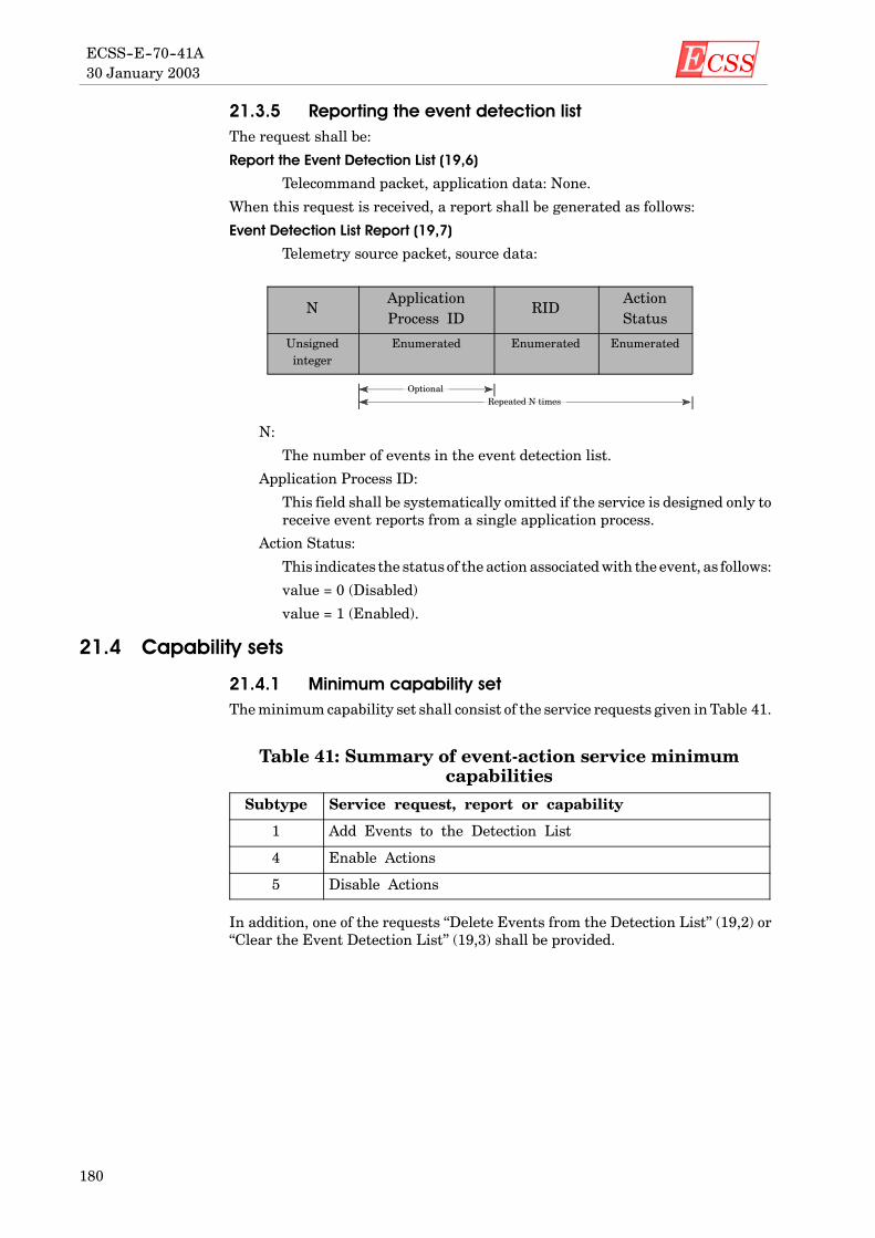
ECSS30 January 2003ECSS--E--70--41A
180
21.3.5 Reporting the event detection listThe request shall be:
Report the Event Detection List (19,6)
Telecommand packet, application data: None.
When this request is received, a report shall be generated as follows:
Event Detection List Report (19,7)
Telemetry source packet, source data:
NApplicationProcess ID
RIDActionStatus
Unsignedinteger
Enumerated Enumerated Enumerated
OptionalRepeated N times
N:
The number of events in the event detection list.
Application Process ID:
This field shall be systematically omitted if the service is designed only toreceive event reports from a single application process.
Action Status:
This indicates the status of the action associatedwith the event, as follows:
value = 0 (Disabled)
value = 1 (Enabled).
21.4 Capability sets
21.4.1 Minimum capability setTheminimum capability set shall consist of the service requests given in Table 41.
Table 41: Summary of event-action service minimumcapabilities
Subtype Service request, report or capability
1 Add Events to the Detection List
4 Enable Actions
5 Disable Actions
In addition, one of the requests “Delete Events from the Detection List” (19,2) or“Clear the Event Detection List” (19,3) shall be provided.

ECSS 30 January 2003
ECSS--E--70--41A
181
21.4.2 Additional capability setsIn addition to a minimum capability set, the additional capabilities given inTable 42 can be implemented.
Table 42: Summary of event-action service additionalcapabilities
Subtype Service request, report or capabilityRequiressubtype
2 Delete Events from the Detection List
3 Clear the Event Detection List
6 Report the Event Detection List 7
7 Event Detection List Report 6

ECSS30 January 2003ECSS--E--70--41A
182
(This page is intentionally left blank)

ECSS 30 January 2003
ECSS--E--70--41A
183
22
Summary of service requests and reports
Table 43 provides a summary of the requests and reports for the services definedwithin this Standard.
Requests appear in the left-hand column and reports in the right-hand column.Reports which are responses are placed in the same row as their correspondingrequests, whilst reports which are indications appear alone in a row.
The subtype (ST) for requests and reports which constitute the minimumcapability set for a given service is indicated in the table by a shaded background.For some services, the minimum capability set can be selected from a number ofalternatives. In these cases, nothing is indicated in this summary table andreference should be made to the corresponding service clause of this Standard.
Table 43: Summary of requests and reports for PUS standard services
ST Service requests ST Service reports
Telecommand verification service - 11 Telecommand Acceptance Report -- Success
2 Telecommand Acceptance Report -- Failure
3 Telecommand Execution Started Report -- Success
4 Telecommand Execution Started Report -- Failure
5 Telecommand Execution Progress Report -- Success
6 Telecommand Execution Progress Report -- Failure
7 Telecommand Execution Completed Report-- Success
8 Telecommand Execution Completed Report-- Failure
Device command distribution service - 21 Distribute On--Off Commands
2 Distribute Register Load Commands
3 Distribute CPDU Commands

ECSS30 January 2003ECSS--E--70--41A
184
Table 43: Summary of requests and reports for PUS standard services(continued)
ST Service reportsSTService requests
Housekeeping and diagnostic data reporting service - 31 Define New Housekeeping Parameter Report
2 Define New Diagnostic Parameter Report
3 Clear Housekeeping Parameter Report Definitions
4 Clear Diagnostic Parameter Report Definitions
5 Enable Housekeeping Parameter ReportGeneration
6 Disable Housekeeping Parameter ReportGeneration
7 Enable Diagnostic Parameter Report Generation
8 Disable Diagnostic Parameter Report Generation
9 Report Housekeeping Parameter ReportDefinitions
10 Housekeeping Parameter Report DefinitionsReport
11 Report Diagnostic Parameter Report Definitions 12 Diagnostic Parameter Report Definitions Report
13 Report Housekeeping Parameter Sampling-TimeOffsets
15 Housekeeping Parameter Sampling-Time OffsetsReport
14 Report Diagnostic Parameter Sampling-TimeOffsets
16 Diagnostic Parameter Sampling-Time OffsetsReport
17 Select Periodic Housekeeping Parameter ReportGeneration Mode
18 Select Periodic Diagnostic Parameter ReportGeneration Mode
19 Select Filtered Housekeeping Parameter ReportGeneration Mode
20 Select Filtered Diagnostic Parameter ReportGeneration Mode
21 Report Unfiltered Housekeeping Parameters 23 Unfiltered Housekeeping Parameters Report
22 Report Unfiltered Diagnostic Parameters 24 Unfiltered Diagnostic Parameters Report
25 Housekeeping Parameter Report
26 Diagnostic Parameter Report
Parameter statistics reporting service - 41 Report Parameter Statistics 2 Parameter Statistics Report
3 Reset Parameter Statistics Reporting
4 Enable Periodic Parameter Statistics Reporting
5 Disable Periodic Parameter Statistics Reporting
6 Add Parameters to Parameter Statistics List
7 Delete Parameters from Parameter Statistics List
8 Report Parameter Statistics List 9 Parameter Statistics List Report
10 Clear Parameter Statistics List
Event reporting service - 51 Normal/Progress Report
2 Error/Anomaly Report -- Low Severity
3 Error/Anomaly Report -- Medium Severity
4 Error/Anomaly Report -- High Severity
5 Enable Event Report Generation
6 Disable Event Report Generation

ECSS 30 January 2003
ECSS--E--70--41A
185
Table 43: Summary of requests and reports for PUS standard services(continued)
ST Service reportsSTService requests
Memory management service - 61 Load Memory using Base plus Offsets
2 Load Memory using Absolute Addresses
3 Dump Memory using Base plus Offsets 4 Memory Dump using Base plus Offsets Report
5 Dump Memory using Absolute Addresses 6 Memory Dump using Absolute Addresses Report
7 Check Memory using Base plus Offsets 8 Memory Check using Base plus Offsets Report
9 Check Memory using Absolute Addresses 10 Memory Check using Absolute Addresses Report
Function management service - 81 Perform Function
Time management service - 9Rate control sub-service
1 Change Time Report Generation Rate
Time reporting sub-service
2 Time Report
On-board operations scheduling service - 111 Enable Release of Telecommands
2 Disable Release of Telecommands
3 Reset Command Schedule
4 Insert Telecommands in Command Schedule
5 Delete Telecommands
6 Delete Telecommands over Time Period
15 Time-Shift All Telecommands
7 Time-Shift Selected Telecommands
8 Time-Shift Telecommands over Time Period
16 Report Command Schedule in Detailed Form 10 Detailed Schedule Report
9 Report Subset of Command Schedule in DetailedForm
(10)
11 Report Subset of Command Schedule in DetailedForm over Time Period
(10)
17 Report Command Schedule in Summary Form 13 Summary Schedule Report
12 Report Subset of Command Schedule in SummaryForm
(13)
14 Report Subset of Command Schedule in SummaryForm over Time Period
(13)
18 Report Status of Command Schedule 19 Command Schedule Status Report
On-board monitoring service - 121 Enable Monitoring of Parameters
2 Disable Monitoring of Parameters
3 Change Maximum Reporting Delay
4 Clear Monitoring List
5 Add Parameters to Monitoring List
6 Delete Parameters from Monitoring List
7 Modify Parameter Checking Information
8 Report Current Monitoring List 9 Current Monitoring List Report
10 Report Current Parameters Out-of-limit List 11 Current Parameters Out-of-limit List Report
12 Check Transition Report

ECSS30 January 2003ECSS--E--70--41A
186
Table 43: Summary of requests and reports for PUS standard services(continued)
ST Service reportsSTService requests
Large data transfer service - 13Data downlink operation
1 First Downlink Part Report
2 Intermediate Downlink Part Report
3 Last Downlink Part Report
4 Downlink Abort Report
5 Downlink Reception Acknowledgement
6 Repeat Parts 7 Repeated Part Report
8 Abort Downlink
Data uplink operation
9 Accept First Uplink Part
10 Accept Intermediate Uplink Part
11 Accept Last Uplink Part
12 Accept Repeated Part
13 Abort Reception of Uplinked Data
14 Uplink Reception Acknowledgement Report
15 Unsuccessfully Received Parts Report
16 Reception Abort Report
Packet forwarding control service - 141 Enable Forwarding of Telemetry Source Packets
2 Disable Forwarding of Telemetry Source Packets
3 Report Enabled Telemetry Source Packets 4 Enabled Telemetry Source Packets Report
5 Enable Forwarding of Housekeeping Packets
6 Disable Forwarding of Housekeeping Packets
7 Report Enabled Housekeeping Packets 8 Enabled Housekeeping Packets Report
9 Enable Forwarding of Diagnostic Packets
10 Disable Forwarding of Diagnostic Packets
11 Report Enabled Diagnostic Packets 12 Enabled Diagnostic Packets Report
13 Enable Forwarding of Event Report Packets
14 Disable Forwarding of Event Report Packets
15 Report Enabled Event Report Packets 16 Enabled Event Report Packets Report
On-board storage and retrieval service - 15Packet selection sub-service
1 Enable Storage in Packet Stores
2 Disable Storage in Packet Stores
3 Add Packets to Storage Selection Definition
4 Remove Packets from Storage Selection Definition
5 Report Storage Selection Definition 6 Storage Selection Definition Report
Storage and retrieval sub-service
7 Downlink Packet Store Contents for PacketRange
8 Packet Store Contents Report
9 Downlink Packet Store Contents for Time Period (8)
10 Delete Packet Stores Contents up to SpecifiedPackets

ECSS 30 January 2003
ECSS--E--70--41A
187
Table 43: Summary of requests and reports for PUS standard services(continued)
ST Service reportsSTService requests
11 Delete Packet Stores Contents up to SpecifiedStorage Time
12 Report Catalogues for Selected Packet Stores 13 Packet Store Catalogue Report
Test service - 171 Perform Connection Test 2 Connection Test Report
On-board operations procedure service - 181 Load Procedure
2 Delete Procedure
3 Start Procedure
4 Stop Procedure
5 Suspend Procedure
6 Resume Procedure
12 Abort Procedure
7 Communicate Parameters to a Procedure
8 Report List of On-board Operations Procedures 9 On-board Operations Procedures List Report
10 Report List of Active On-board OperationsProcedures
11 Active On-board Operations Procedures ListReport
Event-action service - 191 Add Events to the Detection List
2 Delete Events from the Detection List
3 Clear the Event Detection List
4 Enable Actions
5 Disable Actions
6 Report the Event Detection List 7 Event Detection List Report

ECSS30 January 2003ECSS--E--70--41A
188
(This page is intentionally left blank)

ECSS 30 January 2003
ECSS--E--70--41A
189
23
Parameter types and structure rules
23.1 IntroductionEach field in a telecommand or telemetry source packet described in this Standardis either a parameter field containing a parameter value or a structured fieldcontaining several parameter fields organized according to a set of rules.
A parameter field has a simple type defined by the set of values which theparameter can take. The simple types (or parameter types) are defined insubclause 23.5.
A structured field has a structured type indicating the high level organization ofthe field and is defined by reference to one or more other types (the types of itscomponents). The structured types are described in subclause 23.6.
The specification of the structure and content of the source data field (for telemetrysource packets) or application data field (for telecommand packets) in the packetdata field of the packets defined in this Standard is expressed in term of the typesof its simple and structured components.
The various types described in this clause form a subset (sometimes with explicitrestrictions or extensions) of the simple and structured types defined in ISO 8824“Information Technology -- Abstract Syntax Notation One (ASN.1)” (Refer-ence [5]).
The ASN.1 notation is not used in this Standard. A simpler tabular notation isused to describe the packet structures of the service requests and reports specifiedin this Standard. The tabular notation shows the names and order of appearanceof the fields in the packet and the type of each field.
This clause defines the physical encoding rules for each simple and structuredtype, their lengths and the internal format used to encode values.
These encoding rules differ from the rules defined in ISO 8825 “InformationTechnology -- Open Systems Interconnection -- Specification of Basic EncodingRules for Abstract Syntax Notation One (ASN.1)” (Reference [6]) for severalreasons, the main reason being the mission constraints imposed by the space linkbandwidth.
This Standard does not specify a particular length (and physical encoding format)for each field in the packet data field of the packets. Amission shall select for eachfield the length and encoding format which best suit its requirements.

ECSS30 January 2003ECSS--E--70--41A
190
23.2 ConventionsThe following convention is used to identify each bit in an N-bit field:
The first bit in a field, starting from the left, is defined to be “Bit-0”and is represented as the leftmost justified bit on a figure. Thefollowing bit is called “Bit-1”, and so on, up to “Bit-N-1”, the bits beingrepresented in this order from left to right of a figure.
The following nomenclature is used throughout this Standard to describe adjacentgroups of bits within packets:
1 OCTET = 1 BYTE = 8 bits
23.3 Encoding formats of parameter typesThe parameter type defines the abstract class to which the parameter valuesbelong. For a given parameter type there can be variations in the format andlength of the values.
Each combination of a parameter type and encoding format has an associatedparameter code, which identifies completely a simple type and how it is physicallyencoded in a packet.
The parameter code shall be used whenever an explicit definition of a parameterfield is requested.
EXAMPLE To specify the physical format selected by a mission; forparameter interpretation in the ground system.
The parameter codes are valid for both telecommand and telemetry data.
When contained in a packet, the parameter code should consist of two consecutiveparameter fields with type “Enumerated” (as defined later in this clause):
PC = PTC PFC
Enumerated Enumerated
Where:
PTC = Parameter Type Code } PC = Parameter CodePFC = Parameter Format Code } PC = Parameter Code
The only parameter types for telemetry and telecommand parameters shall bethose defined in subclauses 23.5.1 to 23.5.11. For each type of parameter, a list ofstandard parameter formats is defined in this Standard. Missions shall adoptthese standard parameter formats, but other mission-specific parameter formatscan also be defined with new parameter format codes.
NOTE 1 The parameter code only restricts the set of bit combinationsencoding the parameter values. However, the set of valuesthat the parameter may take can be further restricted on amission basis.
NOTE 2 Some simple types have variable-length physical formats(e.g. a variable-length bit string). The actual length isencoded as an unsigned integer field which physicallyprecedes the variable-length value.
Thus, the complete definition of the physical format of a variable-lengthparameter field also includes the parameter code of the field containing theactual length of the parameter value.

ECSS 30 January 2003
ECSS--E--70--41A
191
23.4 Tailoring of packet structures for a missionThe specification of the service requests and reports defined in this Standard onlyindicates the parameter types of the parameter fields in the corresponding packetstructures. During the design phase of amission, the actual physical formats shallbe selected by specifying the parameter code of each parameter field found in eachimplemented packet type and subtype.
EXAMPLE The format of the time field in the packet data header of thetelemetry source packets is selected on the basis of the timeresolution applicable for the monitoring of an applicationprocess.
The actual physical format for a parameter field can be:
a. Mission defined:Thephysical format of the parameter field shall beunique for themission.Theparameter field can appear in different packet types and subtypes or canappear in a packet sent to or generated by different application processes; inall cases its physical format shall be the same.
b. Application process defined:The physical format of the parameter field shall be defined per applicationprocess. The encoding of the parameter field shall be identical in all packettypes and subtypes sent to or generated by the application process.
c. Service instance defined:The physical format of the parameter field shall be defined per serviceprovided by an application process. The encoding of the parameter field shallbe identical in all packet subtypes received or generated by a service providedby a given application process (this can reflect, for example, the fact thatseveral organizations implement the on-board software).
d. Request or report defined:The physical format of the parameter field in a packet shall be deduced fromthe value(s) of one or several preceding parameter fields in the packet(including the packet type and subtype). It can additionally depend on thevalue(s) of one or several mission constant(s), on the destination (or source)application process and on the service provided by the application process.
The actual type of a parameter field in a packet can also be mission defined,application process defined, service instance defined or request or report defined.The specification of the packet structures defined in this Standard highlightswhich parameter fields shall have their types defined in this way by indicatingthat their type is “Deduced”.
The presence or absence of a parameter field specified as “Optional” in thestructure of a packet can be mission defined, application process defined, serviceinstance defined or request or report defined. The level at which a given field isoptional is explained within the corresponding definition for that field.
A mission can specify that a parameter field starts on a byte boundary, or on a16-bit, 24-bit, 32-bit or 64-bit word boundary. This can be achieved by ensuringthat the preceding parameter field ends on a word boundary (increasing its sizeif necessary) or by introducing paddingbits between two parameter fields. All suchpadding bits shall be set to zero.
When tailoring the PUS, a mission may decide to implement only a subset of theparameter types or formats defined in the following subclause.
When a mission tailors the packet structures to suit its requirements, it shouldtake into account the impact on related data processing systems and databases.

ECSS30 January 2003ECSS--E--70--41A
192
23.5 Simple parameter types
23.5.1 Boolean parameter (PTC = 1)PFC = 0
This is a one-bit parameter, with two distinguished values only, involved in logicaloperations where:
value 1 denotes “TRUE”
value 0 denotes “FALSE”.
23.5.2 Enumerated parameter (PTC = 2)PFC = 1, 2, 3, 4, 5, 6, 7, 8, 9, 10, 11, 12, 13, 14, 15, 16, 24 or 32: length in bits of
the parameter values
This is a parameter, with discrete integer values only, involved in logical andcomparative expressions (but not in numeric and relational expressions). Thevalues that such a parameter can take are discrete and unordered. Each value hasa meaning which is interpreted as a character string value. An error code is atypical example (e.g. 0 means “unchecked”, 3 means “invalid”).
23.5.3 Unsigned integer parameter (PTC = 3)The values that this parameter can take are positive and can be involved inarithmetical, relational and comparative expressions. An unsigned integer shallbe encoded with Bit-0 being the most significant bit (MSB) and Bit-N-1 the leastsignificant bit (LSB).
The formats of an unsigned integer shall be:
Format Code Format Definition Lowest Value Highest Value
0 ≤ PFC ≤ 12 PFC +4 bits, unsigned 0 2PFC+4–1(15 to 65535)
PFC = 13 3 octets, unsigned 0 224–1(16777215)
PFC = 14 4 octets, unsigned 0 232–1(≅ 4,3*109)
PFC = 15 6 octets, unsigned 0 248–1(≅ 2,8*1014)
PFC = 16 8 octets, unsigned 0 264–1(≅ 18,5*1018)
23.5.4 Signed integer parameter (PTC = 4)The values that such a parameter can take are positive or negative and can beinvolved in arithmetical, relational and comparative expressions.
D If Bit-0 = 0, the value shall be positive following the unsigned integerconvention.
D If Bit-0 = 1, the value shall be negative and the field is the 2’s complement ofthe positive value.

ECSS 30 January 2003
ECSS--E--70--41A
193
The formats of a signed integer shall be:
Format Code Format Definition Lowest Value Highest Value
0 ≤ PFC ≤ 12 PFC +4 bits, signed --2PFC+3
(--8 to --32768)2PFC+3--1(7 to 32767)
PFC = 13 3 octets, signed --223
(--8388608)223--1(8388607)
PFC = 14 4 octets, signed --231
(≅ --2,15*109)231--1(≅ 2,15*109)
PFC = 15 6 octets, signed --247
(≅ --1,4*1014)247--1(≅ 1,4*1014)
PFC = 16 8 octets, signed --263
(≅ --9,2*1018)263--1(≅ 9,2*1018)
23.5.5 Real parameter (PTC = 5)PFC = 1: 4 octets simple precision format (IEEE standard).
PFC = 2: 8 octets double precision format (IEEE standard).
PFC = 3: 4 octets simple precision format (MIL standard).
PFC = 4: 6 octets extended precision format (MIL standard).
23.5.5.1 IEEE standard format
The simple-precision format and the double-precision format are defined in “IEEE754 Standard for Binary Floating-Point Arithmetic” (Reference [7]). Theimportant features of their definitions are repeated here.
Each format permits the representation of the numerical values of the form:
(--1)S × 2E × (b0•b1b2.....bp--1)where:
b0•b1b2...bp--1 means b0/ 20 +b1/21 + b2/22 + ------ + bp--1/2p--1;
S = 0 or 1;
E = any integer between Emin and Emax, inclusive;
bI = 0 or 1;
p = number of significant bits (precision).
Each format also permits the representation of two infinities, “+∞” and “--∞” andspecial values which are not numbers.
Real numbers in both formats are composed of 3 subfields:
Sign unsigned integer, contains the value SExponent unsigned integer, contains the value E+127 on 8
bits (single precision) or E+1023 (doubleprecision)
Fraction bit string, contains the value •b1b2.....bp--1 withp = 24 (single precision) or p = 53 (doubleprecision)
The encoded value of a single-precision real parameter shall be constituted asfollows:
Sign Exponent Fraction
1 bit 8 bits 23 bits

ECSS30 January 2003ECSS--E--70--41A
194
The value of a single-precision parameter shall be:
Value
If exponent = 255 and fraction <> 0 Not a Number
If exponent = 255 and fraction = 0 (--1)sign × ∞
If 0 < exponent < 255 (--1)sign × 2exponent--127 × (1,fraction)
If exponent = 0 and fraction <> 0 (--1)sign × 2--126 × (0,fraction)
If exponent = 0 and fraction = 0 0
The encoded value of a double-precision real parameter shall be constituted asfollows:
Sign Exponent Fraction
1 bit 11 bits 52 bits
The value of a double-precision parameter shall be:
Value
If exponent = 2047 and fraction <> 0 Not a Number
If exponent = 2047 and fraction = 0 (--1)sign × ∞
If 0 < exponent < 2047 (--1)sign × 2exponent--1023 × (1,fraction)
If exponent = 0 and fraction <> 0 (--1)sign × 2--1022 × (0,fraction)
If exponent = 0 and fraction = 0 0
In the cases where Exponent = 0 and Fraction <> 0, the values are calleddenormalized.
The range of possible values and precision for a real parameter are as follows:
Simple precision:
1,12*10--38 ≤ |value| ≤ 3,40*1038 (precision 1,15*10--7)
Double precision:
2,22*10--308 ≤ |value| ≤ 1,79*10308 (precision 2,22*10--16)
23.5.5.2 United States Air Force (USAF) military standard format
This is defined in “Military Standard Sixteen-Bit Computer Instruction SetArchitecture” MIL--STD--1750a, 2nd July 1980 (Reference [8]) and this definitionis repeated below:
Simple precision floating point data:
This shall be represented as a 32-bit quantity consisting of a 24-bit 2’s complementmantissa and an 8-bit 2’s complement exponent.
MSB LSB MSB LSB
S Mantissa Exponent
0 1 23 24 31
Floating point numbers are represented as a fractional mantissa times 2 raised tothe power of the exponent. All floating point numbers are assumed normalized orfloating point zero at the beginning of a floating point operation and the results

ECSS 30 January 2003
ECSS--E--70--41A
195
of all floatingpoint operationsarenormalized (a normalized floating pointnumberhas the sign of the mantissa and the next bit of opposite value) or floating pointzero. A floating point zero is defined as 0000 000016, that is, a zero mantissa anda zero exponent (0016). An extended floating point zero is defined as 0000 0000000016, that is, a zero mantissa and a zero exponent. Some examples of themachine representation for 32-bit floating point numbers are:
Decimal Number Hexadecimal Notation
Mantissa Exp
0,9999998 × 2127 7FFF FF FF
0,5 × 2127 4000 00 7F
0,625 × 24 5000 00 04
0,5 × 21 4000 00 01
0,5 × 20 4000 00 00
0,5 × 2--1 4000 00 FF
0,5 × 2--128 4000 00 80
0,0 × 20 0000 00 00
--1,0 × 20 8000 00 00
--0,5000001 × 2--128 BFFF FF 80
--0,7500001 × 24 9FFF FF 04
Extended Precision Floating Point Data:
Extended floating point data shall be represented as a 48-bit quantity consistingof a 40--bit 2’s complement mantissa and an 8--bit 2’s complement exponent. Theexponent bits 24 to 31 lie between the split mantissa bits 0 to 23 and bits 32 to 47.The most significant bit of the mantissa is the sign bit 0, and the least significantbit of the mantissa is bit 47.
S Mantissa MS Exponent Mantissa LS
0 1 23 24 31 32 47

ECSS30 January 2003ECSS--E--70--41A
196
Some examples of the machine representation of 48-bit extended floating pointnumbers are:
Decimal Number Mantissa (MS) Exp Mantissa (LS)
0,5 × 2127 400000 7F 0000
0,5 × 20 400000 00 0000
0,5 × 2--1 400000 FF 0000
0,5 × 2--128 400000 80 0000
--1,5 × 2127 800000 7F 0000
--1,0 × 20 800000 00 0000
--1,0 × 2--1 800000 FF 0000
--1,0 × 2--128 800000 80 0000
0,0 × 20 000000 00 0000
--0,75 × 2--1 A00000 FF 0000
For both floating point and extended floating point numbers, an overflow isdefined as an exponent overflow and an underflow is defined as an exponentunderflow.
23.5.6 Bit-string parameter (PTC = 6)PFC = 0: A variable-length bit string.
PFC > 0: A fixed-length bit string with a number of bits equal to PFC.
The values that such a parameter can take are variable-length or fixed-lengthsequences of bits, each with a value 1 or 0. The meaning and interpretation of avalue is application process specific.
A variable-length bit-string parameter shall be of the form:
n B1…BnUnsigned Integer n bits
Where:
B1…Bn are bits;
n indicates the number of bits which follows.
A fixed-length bit-string parameter shall be of the form:
B1…Bnn bits
Where:
B1…Bn are bits;
n is the number of bits and is equal to PFC.
23.5.7 Octet-string parameter (PTC = 7)PFC = 0: A variable-length octet string.
PFC > 0: A fixed-length octet string with a number of octets equal to PFC.

ECSS 30 January 2003
ECSS--E--70--41A
197
The values that such a parameter can take are variable-length or fixed-lengthsequences of octets, each octet being an ordered sequence of eight bits. Themeaning and interpretation of a value shall be application process specific.
A variable-length octet-string parameter shall be of the form:
n O1 O2 … On
Unsigned Integer octet octet octet
Where:
O1…On are octets;
n indicates the number of octets which follow.
A fixed-length octet-string parameter is of the form:
O1 O2 … On
octet octet octet
Where:
O1…On are octets;
n is the number of octets and is equal to PFC.
23.5.8 Character-string parameter (PTC = 8)PFC = 0: A variable-length character string.
PFC > 0: A fixed-length character string with a number of characters equal toPFC.
The values that such a parameter can take are variable-length or fixed-lengthsequences of visible characters (visible characters are defined in ANSI X3.4Reference [9]). A visible character shall be represented by its ASCII code on oneoctet. The meaning and interpretation of a value is application process specific.
A variable-length character-string parameter shall be of the form:
n C1 C2 … CnUnsigned Integer ASCII ASCII ASCII
Where:
C1…Cn are ASCII character codes on 8 bits;
n indicates the number of ASCII character codes which follow.
A fixed-length character-string parameter shall be of the form:
C1 C2 … CnASCII ASCII ASCII
Where:
C1…Cn are ASCII character codes;
n is the number of ASCII character codes and is equal to PFC.

ECSS30 January 2003ECSS--E--70--41A
198
23.5.9 Absolute time parameter (PTC = 9)PFC = 0: Explicit definition of time format (CUC or CDS), i.e. including the P-
field.
PFC = 1: 2 octets day CDS format without a µs field (parameter field is6 octets).
PFC = 2: 2 octets day CDS format with a µs field (parameter field is 8 octets).3 ≤ PFC ≤ 18:
CUC format with ((PFC +1)÷4, rounded down) octets of coarse timeand ((PFC +1) modulo 4) octets of fine time. PFC values in this rangedo not include the P-field (the value of the implicit P-field can be de-rived from the PFC).
The CUC and CDS time formats are defined in CCSDS 301.0--B--2.
The value of an Absolute Time parameter field shall be a number of seconds andfractions of second from a given Agency epoch. It shall be a positive time offset.
CDS format
The CDS Format with µs (PFC = 2) shall be as follows:
Day msec of day µsec of msec
2 octets 4 octets 2 octets
The value of Day is an unsigned integer in the range 0 to 216--1.
CUC format
The full CUC Format shall be as follows:
C1 C2 C3 C4 F1 F2 F31 octet 1 octet 1 octet 1 octet 1 octet 1 octet 1 octet
The time in seconds from the given Agency epoch is given by:
t = C1*2563 + C2*2562 + C3*256 + C4 + F1*256--1 + F2*256--2 + F3*256--3.
23.5.10 Relative time parameter (PTC = 10)PFC = 0: Explicit definition of CUC time format, i.e. including the P-field
1 ≤ PFC ≤ 16:CUC format with ((PFC +3)÷4, rounded down) octets of coarse timeand ((PFC +3) modulo 4) octets of fine time. PFC values in this rangedo not include the P-field (the value of the implicit P-field can be de-rived from the PFC).
The value of a Relative Time parameter field shall be a number of seconds andfractions of a second from the occurrence time of an eventwhose identification canbe derived from other parameters in the packet (e.g. identifying a type of on-boardevent) or a number of seconds and fractions of a second between two absolutetimes. It can be a positive or negative time offset.
The full CUC Format shall be as follows:
C1 C2 C3 C4 F1 F2 F31 octet 1 octet 1 octet 1 octet 1 octet 1 octet 1 octet
A positive time offset is given by:
t = C1*2563 + C2*2562 + C3*256 + C4 + F1*256--1 + F2*256--2 + F3*256--3
where C1 is in the range 0 to 127.

ECSS 30 January 2003
ECSS--E--70--41A
199
A negative time offset is expressed as the “2’s complement” of the correspondingpositive time offset.
23.5.11 Deduced parameter (PTC = 11)PFC = 0
A type which is unspecified and can only be instantiated to one of the simple typesdefined in the previous subclauses. Its actual type and encoding format for aninstance of the parameter field in a packet is deduced from the value(s) of otherprecedingparameter field(s) in thepacketor fromthe value(s) ofmission constantsor a combination of both.
EXAMPLE A telemetry source packet source data field which containstwo parameter fields, the first field being the explicitidentification of a parameter and the second field the valueof that parameter, as illustrated below:
Parameter# Parameter Value
Enumerated Deduced
In this example, successive packets generated by an applica-tion process can contain different identifiers of telemetryparameters having different types of parameter value, thusthe type of the Parameter Value field is unspecified, whilstits actual type in a packet is deduced from the value in theParameter# field.
23.6 Structured field types
23.6.1 IntroductionThe packet data field structure and any structured fieldwithin it, in particular thesource data field or the application data field, shall be defined bya structured type.The structured types of fields shall be defined through rules specifying how toorganize the component fields which constitute the field body.
Within this Standard, there is only one set of valid structure rules for bothtelecommand and telemetry structured fields, and all specialized packet struc-tures within this Standard follow these rules. This set is referred to as structurerules set #1 and is defined below.
23.6.2 Structure rules set #1The structured types shall be:
D Record type: this defines a field which is composed of a fixed number ofdistinct components where each component has its own type (simple orstructured).
D Array type: this defines a field which is composed of zero, one or morecomponents where all the components shall be of an identical type (simple orstructured).
An array canhave a fixed number of entries (fixedarray) or a variable numberof entries (variable array).
D Deduced structure type: this defines a field which is composed of onecomponentwhose actual type (simple or structured) shall be deduced fromthevalue(s) of other preceding parameter field(s) in the packet or from thevalue(s) of mission constants or a combination of both.
A deduced parameter field (see subclause 23.5.11) is a particular case of adeduced structure field.

ECSS30 January 2003ECSS--E--70--41A
200
There isno limitation on the level of nesting of componentswithinpackets, but thisStandard defines specific limitations for some types of packets (other limitationscan also be defined by a mission).
The structure rules set #1 utilize the diagram conventions shown in Figure 10.
An oval denotes adefinition of a simplecomponent
A box denotes acomponent built fromsimple or structuredcomponents
An exclusive “OR”
A repetition of componentsa fixed number of times,which is known implicitly
*
*N
A repetition of the samecomponent a fixed numberof times, which is knownimplicitly.
A repetition of the samecomponent N times.
Figure 10: Diagram conventions used by the structure rules set #1

ECSS 30 January 2003
ECSS--E--70--41A
201
Structure Rules (Set number 1)
BOOLEAN
PARAMETER
PARAMETER
F--ARRAY
V--ARRAY
DEDUCED STRUCT
RECORD
A record is a sequence of distinctparameters, arrays or deducedstructures, where the structure ofthe record is known implicitly
RECORD
*
F--ARRAY
A “Fixed Array” is a repetition ofone record n times, where n isknown implicitly
A “Variable Array” is a repetitionof one record D times, where D isgiven explicitly. A Variable Arraycan only be empty if so stated in itsdefinition (in which case the valueD=0 is still present).
INTEGER
REAL
STRING
TIME
DEDUCED
ANYDEDUCED STRUCTURE
An instance of a “DeducedStructure” can be of any type(simple or structured)
ENUMERATED
RECORD*n
D
Condition1
*Otherconditions
INTEGER
V--ARRAY
Figure 10 (continued): Diagram conventions used by the structure rulesset #1

ECSS30 January 2003ECSS--E--70--41A
202
A “Deduced Structure” cannot be fully represented with the same diagramconventions since the actual type for an instance of the deduced structure ina packet shall be deduced from the value(s) of one or several precedingparameter field(s) in the packet or from the value(s) of one or several missionconstants (called “determining parameters”) or a combination of both.However, within a given instance of a packet, the deduced structure shall beeither a parameter, a record, a variable array, a fixed array or even nothing.
EXAMPLE A determining parameter can be an explicit sampling timeor indicate an event to which the values in the deducedstructure relate.
There shall be a direct correspondence between the value(s) of the set ofdetermining parameter(s) and the deduced structure instance (e.g. a look-uptable can be used).
EXAMPLE A deduced structure dependent on a preceding parameterfield P can be a variable array when P = 0, a record A whenP= 1and another recordBwhenP= 2 (see the correspondingillustration at the end of subclause 23.6.4).
The type of adeterminingparameter canonly beBoolean, enumerated, signedor unsigned integer or a character string. It can also be deduced, inwhich caseits actual type shall depend on the value(s) of some of the other determiningparameters.
NOTE The determining parameter(s) do not need to be placedconsecutively in the packet or placed just before the deducedstructure (i.e. there can be other fields separating them).
If an array entry contains a deduced structure, then the entry number canalso be used to determine the type of the deduced structure instance.
23.6.3 Nesting and identification rules (NIR)D NIR1:
By definition, in a packet all components which are not components of anyarray are at level 1. Therefore an array is itself at level 1 if it is an array notnested in another array.
D NIR2:
In a packet, all fields which are components of an array are said to be at thelevel of the array plus one. By convention, this shall apply to the array entrynumber which is considered to be an implicit component of the array if it isused for determining the type of a deduced structure instance.
The implications of the two foregoing rules are indicated below each examplepresented in subclause 23.6.5.
D NIR3:
A parameter field in a packet can contain:
1. The value of a concrete parameter, such as the sampled value of anon-board measurement or the value of a threshold to be set. A concreteparameter shall have a uniquely identifying name and its meaning andinterpretation shall be uniquely defined for a mission.

ECSS 30 January 2003
ECSS--E--70--41A
203
2. The value of a formal parameter. A formal parameter field shall have ameaning and interpretation which is defined with respect to one or morecomponent(s).
EXAMPLE A parameter field T providing the time of sampling of aconcrete parameter P is formal (its meaning is “samplingtime of P”). In the example presented in subclause 23.5.11,both parameter fields are formal: the meaning of Para-meter# is “identification of a concrete parameter” and themeaning of Parameter Value is “value of concrete parameteridentified by Parameter#”.
D NIR4:
A concrete parameter can only be explicitly named once in thedefinition of thecontents of a packet and at level 1 or 2 (therefore all parameters at level 3 andabove are formal).
This implies that the values of a concrete parameter sampled several timesper packet cannot be scattered “randomly” in a packet but shall becomponents of one, and only one, array. Also, a concrete parameter may onlyoccur in certain instances of a packet if it appears in the definition of a singlededuced structure at level 1 or 2.
D NIR5:
A concrete parameter canbe explicitly namedmore than once in thedefinitionof a packet if it has a specialized meaning in each case.
EXAMPLE If it appears in a deduced structure providing information onan event, the specialized meaning can be “value of concreteparameter when event occurred”.
This implies that the packet contains formal parameter fields which hold the“special purposes” values of the concrete parameter (these values can bescattered “randomly” in these packet).
D NIR6:
The last (or only) determining parameter of a deduced structure shall be atthe same level or at one level less than the level of its deduced structure. Thefirst determining parameter of a deduced structure shall be at level 1 or 2, andthere shall be at least one determining parameter at each level between thelevel of the first determining parameter and the level of the last determiningparameter.
This rule denotes the fact that an array hierarchy provides informationwhichrelates to a functional or physical hierarchy for which the determiningparameter(s) define an access and interpretation path.
23.6.4 Encoding of the structured fieldsThe rules for the construction of structured types which are described in theprevious subclause do not specify how the resulting construct shall be physicallyencoded in the packets.
This subclause specifies the encoding rules for the structured type fields. Theserules apply recursively.
Record Type
The fixed number (N) of ordered components of a record shall be placedconsecutively in the packet, by means of their own physical encoding format:
Component 1 … Component N
Component 1 Type Component N Type

ECSS30 January 2003ECSS--E--70--41A
204
A parameter field shall be bit-wise aligned with the last bit of the parameterfield which precedes it and shall occupy exactly the number of bits defined forits physical encoding (as definedby itsPFC). A specific number of paddingbits(see subclause 23.4) can be introduced before the first component andbetween two successive components.
The value of a variable-length parameter type shall occupy exactly the actualnumber of bits applicable for the physical encoding of its length field and ofits value field (as defined by their PFCs).
Array Type
The ordered set of entries of an array shall be placed consecutively in thepacket and shall be bit-wise aligned.Padding bits can be introduced before thearray and between the successive entries of the array.
The set of entries of a variable array shall be preceded by an unsigned integerparameter fieldwhose value (D) is the number of entries in the variable array:
D Entry 1 … Entry D
Unsigned Integer Array Item Type Array Item Type
Deduced Structure Type
The deduced structure shall be placed in the packet by means of the encodingformat of its actual structure instance. It shall be bit-wise aligned with thepreceding field in the packet. Padding bits can be introduced before thededuced structure (this applies to all structure instances).
EXAMPLE If a deduced structure S depends on the value of a precedingdetermining parameter P, the generic structure shall be:
… P … S
Enumerated Deduced Structure
The actual variants of this deduced structure might be
S a variable array when P = 0,
S a record A when P = 1 and
S a record B when P = 2.
The three resulting packet structures are:
… P = 0 … D Entry 1 Other Entries Entry D
Enumerated Unsigned Integer Array Item Type … Array Item Type
Variable Array
… P = 1 … Component A1 Other Components Component An
Enumerated Component A1 Type … Component An Type
Record A
… P = 2 … Component B1 Other Components Component BmEnumerated Component B1 Type … Component Bm Type
Record B

ECSS 30 January 2003
ECSS--E--70--41A
205
23.6.5 Examples of structure rules set #1A simple example of the use of the structure rules set #1 is a classical structure ofthe parameters field of a housekeeping packet that contains only single samplesof parameters, viz.:
Ra
Pa Pb Pc Pd Pe Pf Pg Ph Pi Pj Pk Pl Pm Pn Po Pp
In the above example, Ra and its components (Pa to Pp) are at level 1.
On the other hand, the following structure utilizes the array constructs defined instructure rules set #1:
Ra
Rb Rc FAa VAa Rd
Pa Pb Pc Pd Re Re Re D=3 Rf Rf Rf Ph Pi
Pe Pf Pe Pf Pe Pf Pg Pg Pg
P = Parameter; R = Record; FA = Fixed array; VA = Variable array.
In the second example, Rb and Rc can be combined into one record withoutchanging the lower level structure. However, it can often be useful to defineseparate records corresponding to different sets of information which can appearelsewhere in different structures.
In the second example, Ra, Rb, Rc, Rd (and their components), FAa, VAa and D areat level 1 while Re and Rf (and their components) are at level 2.

ECSS30 January 2003ECSS--E--70--41A
206
(This page is intentionally left blank)

ECSS 30 January 2003
ECSS--E--70--41A
207
Annex A (normative)
Examples
A--A--
A.1 Specification of the cyclic redundancy code (CRC)
A.1.1 General specificationThe packet error control field provides the capability for detecting errors whichhave been introduced into the telemetry source packet (or telecommand packet)by the lower layers during the transmission process or during other processing orstorage activities.
The standard error detection encoding/decoding procedure, which is described indetail in the following subclauses, produces a 16-bit PacketCheck Sequence (PCS)which is placed in the packet error control field. The characteristics of the PCSarethose of a cyclic redundancy code, and can be expressed as follows:
a. The generator polynomial is:
g(x) = x16 + x12 + x5 + 1
b. Both encoder anddecoder are initialized to the “all-ones” state for eachpacket.
c. PCS generation is performed over the data space “D” as shown in Figure A--1where “D” covers the entire packet including the packet header but excludingthe final packet error control field.
d. The error detection properties of the CRC can be expressed as follows:
1. The proportion of all errors in the data that are not detected isapproximately 1,53 × 10--5.
2. An error in the data affecting an odd number of bits shall always bedetected.
3. An error in the data affecting exactly two bits, no more than 65535 bitsapart, shall always be detected.
4. If an error in the data affects an even number of bits (greater than or equalto 4), the probability that the error shall not be detected is approximately3 × 10--5 for a data length of 4096 octets. The probability increases slightlyfor larger data lengths and decreases slightly for smaller data lengths.
5. A single error burst spanning 16 bits or less of the data shall always bedetected.Not all intermediate bits in the error burst spanneed be affected.
This code is intended only for error detection purposes and no attempt should bemade to utilize it for correction.

ECSS30 January 2003ECSS--E--70--41A
208
Packet
“D” DATA SPACE PCS
7 to 65 540 OCTETS 2 OCTETS
Figure A--1: Standard packet check sequence generation
A.1.2 Encoding procedureThe encoding procedure accepts an (n-16)-bitmessage and generates a systematicbinary (n, n-16) block code by appending a 16-bit Packet Check Sequence (PCS)as the final 16 bits of the block. This PCS is inserted into the packet error controlfield. The equation for PCS is:
PCS = [x16 × M(x) + x(n--16) × L(x)] MODULO G(x)
where:
M(x) is the (n-16)-bitmessage to be encoded expressedasapolynomialwithbinary coefficients, n being the number of bits in the encodedmessage(i.e. the number of bits in the complete packet).
L(x) is the presetting polynomial given by:
L(x)=15i=0
xi(all “1” polynomial of order 15)
G(x) is the CCITT recommendation V.41 (Reference [10]) generating poly-nomial given by:
G(x) = x16 + x12 + x5 + 1
+ is the modulo 2 addition operator (Exclusive OR).
NOTE The encoding procedure differs from that of a conventionalcyclic block encoding operation in that the x(n--16) ×L(x) termhas the effect of presetting the shift register to an all onesstate (rather than a conventional all zeros state) prior toencoding.
A.1.3 Decoding procedureThe error detection syndrome, S(x) is given by:
S(x) = [x16 × C*(x) + xn × L(x)] MODULO G(x)
where:
C*(x) is the received block in polynomial form.
S(x) is the syndrome polynomial which is zero if no error has been de-tected.
A.1.4 Realization of a CRC encoder - decoder
A.1.4.1 General
This subclause describes two arrangements, based on a shift register, for encodingand decoding a telemetry source packet (or telecommand packet) according to thepacket check sequence procedures defined above.
A.1.4.2 Encoder
Figure A--2 shows an arrangement for encoding with the aid of a shift register. Toencode, the storage stages are set to “one”, gates A and B are enabled, gate C isinhibited, and (n--16) message bits are clocked into the input. They appearsimultaneously at the output.

ECSS 30 January 2003
ECSS--E--70--41A
209
After the bits have been entered, the output of gate A is clamped to “zero”, gate Bis inhibited, gate C is enabled, and the register is clocked a further 16 counts.During these counts, the applicable check bits appear in succession at the output.
GATE A
GATE B
GATE C
5-BIT SHIFTREGISTER
7-BIT SHIFTREGISTER
4-BIT SHIFTREGISTER+ + +
INPUT OUTPUT
Figure A--2: Encoder
A.1.4.3 Decoder
Figure A--3 shows an arrangement for decoding with the aid of a shift register. Todecode, the storage stages are set to “one” and gate B is enabled.
The received n bits (i.e. the (n--16) message bits plus the 16 bits of PCS) are thenclocked into the input and after (n--16) counts gate B is inhibited. The 16 check bitsare then clocked into the input and the contents of the storage stages are thenexamined.For an error-free packet, the contents shall be “zero”.Non-zero contentsindicates an erroneous packet.
GATE A
GATE B
5-BIT SHIFTREGISTER
7-BIT SHIFTREGISTER
4-BIT SHIFTREGISTER+ + +
INPUT OUTPUT
Figure A--3: Decoder

ECSS30 January 2003ECSS--E--70--41A
210
A.1.5 Verification of complianceThe binary sequences defined in this subclause are provided to the designers ofpacket systems as samples for early testing, so that they may verify thecorrectness of their CRC error-detection implementation.
All data are given in hexadecimal notation. For a given field (data or CRC) theleftmost hexadecimal character contains the most significant bit.
Data CRC
00 0000 00 00AB CD EF 0114 56 F8 9A 00 01
1D 0FCC 9C04 A27F D5
A.1.6 Software implementation
A.1.6.1 Introduction
In addition to their interesting performance, CRC codes are particularly efficientwhen it comes to hardware implementation. Software implementation, on theother hand, is more complex.
The following C-language code describes the software routines to implement theCRC encoder. To implement the CRC decoder, the same routines can be used: dataand the syndrome are encoded and the resulting syndrome should be equal to zeroif no error is present.
A.1.6.2 Functions applicable to generate the CRC placed at the end of apacket.
a. Crc FUNCTION
The Crc function calculates the CRC for one byte in serial fashion and returnsthe value of the calculated CRC checksum.
b. Crc_opt FUNCTION
This function can be used instead of the Crc function given above.
The Crc_opt function generates the CRC for one byte and returns the valueof the new syndrome. This function is approximately 10 times faster than thenon-optimized Crc function.
c. InitLtbl FUNCTION
The InitLtbl function initiates the look-up table used by Crc_opt.
unsigned int Crc(Data, Syndrome)
unsigned char Data; /* Byte to be encoded */
unsigned Syndrome; /* Original CRC syndrome */
{
int i;
for (i=0; i<8; i++) {
if ((Data & 0x80) ^ ((Syndrome & 0x8000) >> 8)) {
Syndrome = ((Syndrome << 1) ^ 0x1021) & 0xFFFF;
} else {
Syndrome = (Syndrome << 1) & 0xFFFF;
}
Data = Data << 1;

ECSS 30 January 2003
ECSS--E--70--41A
211
}
return (Syndrome);
}
unsigned int Crc_opt (D, Chk, table)
unsigned char D; /* Byte to be encoded */
unsigned int Chk; /* Syndrome */
unsigned int table [ ]; /* Look-up table */
{
return (((Chk << 8) & 0xFF00)^table [(((Chk >> 8)^D) & 0x00FF)]);
}
void InitLtbl (table)
unsigned int table [ ];
{
unsigned int i, tmp;
for (i=0; i<256; i++) {
tmp=0;
if ((i & 1) != 0) tmp=tmp ^ 0x1021;
if ((i & 2) != 0) tmp=tmp ^ 0x2042;
if ((i & 4) != 0) tmp=tmp ^ 0x4084;
if ((i & 8) != 0) tmp=tmp ^ 0x8108;
if ((i & 16) != 0) tmp=tmp ^ 0x1231;
if ((i & 32) != 0) tmp=tmp ^ 0x2462;
if ((i & 64) != 0) tmp=tmp ^ 0x48C4;
if ((i & 128) != 0) tmp=tmp ^ 0x9188;
table [i] = tmp;
}
}
/* Simple program to test both CRC generating functions */
void main ( )
{
unsigned int Chk; /* CRC syndrome */
unsigned int LTbl[256]; /* Look-up table */
unsigned char indata[32]; /* Data to be encoded*/
int j;
indata[0] = 0x31; indata[1] = 0x23; indata[2] = 0x48; indata[3] = 0x07;
indata[4] = 0x00; indata[5] = 0xEC; indata[6] = 0xD0; indata[7] = 0x37;
Chk = 0xFFFF; /* Reset syndrome to all ones */
for (j=0; j<8; j++) {
Chk = Crc(indata[j], Chk); /* Unoptimized CRC */
}

ECSS30 January 2003ECSS--E--70--41A
212
printf(” CRC = %x (should be 0)\n”,Chk);
InitLtbl(LTbl); /* Initiate look-up table */
Chk = 0xFFFF; /* Reset syndrome to all ones */
for(j=0;j<8;j++) {
Chk = Crc_opt(indata[j],Chk,LTbl); /* Optimized CRC */
}
printf(” CRC = %x (should be 0)\n”, Chk);
}
A.2 Specification of the ISO checksum
A.2.1 General specificationThe standard error detection encoding or decoding procedure, which is describedin detail in the following subclauses, produces a 16-bit checksum (the “ISOChecksum”) using integer arithmetic (see J.G. Fletcher (Reference [3]) and ISO8473--1:1998 (Reference [4])).
The ISO checksumprocedure can be easily implemented in software on processorsusing a compact and efficient algorithm. In contrast to the CRC algorithms (seesubclause A.1), it does not use a look-up table and does not perform bit-wiseoperations on the data to be checked. Indeed, it only performs integer arithmeticon the octets of the data to be checked.
This Standard specifies that the ISO checksum procedure shall be used to checkthe contents of an on-board memory area using the services of the memorymanagement service (see clause 11). All octets of the on-board memory area shallbe processed in turn and the calculated ISO checksum value shall be placed in thechecksum field of the Memory Check Report.
This Standard also specifies that the ISO checksum procedure can be used todetect errors which have been introduced into a telemetry source packet (or atelecommand packet) during packet processing, transmission or storage activity.All octets of the entire packet including the packet header but excluding the finalpacket error control field shall be processed in turn and the calculated ISOchecksum value shall be placed in the packet error control field.
The error detectionproperties of the ISOchecksumprocedure are almost the equalof those of the CRC. The error detection properties can be expressed as follows:
a. The proportion of all errors in the data that are not detected is approximately1,54 × 10--5, i.e. the checksum detects virtually the same proportion of allerrors as does the CRC.
b. A single bit in error shall always be detected.
c. In contrast to the CRC, an error in the data which affects an odd number ofbits is not always detected. However, since the checksum has essentially thesame overall detection capability as the CRC, this is compensated by moredetections of an error in the data which affects an even number of bits.
d. An error in the data affecting exactly two bits, no more than 2040 bits apart,shall always be detected.
e. The probability that a single error burst spanning 16 bits or less of the datashall not be detected is approximately 1,9 × 10--7. Not all intermediate bits inthe error burst span need be affected.
This probability is non-zero because the algorithm does not detect an error burstwhich causes 8 consecutive bits to change from all zeros to all ones or vice-versa.
This code is intended only for error detection purposes and no attempt should bemade to utilize it for correction.

ECSS 30 January 2003
ECSS--E--70--41A
213
A.2.2 Symbols and conventionsC0, C1 are variables used in the encoding and decoding procedures;
Bi is the integer value of the ith octet to be checked;
N is the number of octets of data to be checked;
CK1 is the value of the left most octet of the calculated checksum;
CK2 is the value of the right most octet of the calculated checksum.
Addition is performed modulo 255 (1’s complement arithmetic).
A.2.3 Encoding procedureThe encoding procedure accepts N octets of data to be checked and generates asystematic 16-bit checksum value. This checksum value is placed in thedestination field (e.g. the packet error control field).
The algorithm is:
a. Initialize C0 and C1 to zero.
b. Process each octet of the data to be checked sequentially from i = 1 to N asfollows:
C0 = C0 + BiC1 = C1 + C0On completion, we have:
C0 =Ni=1
Bi
C1 =Ni=1
(N− i+ 1) * Bi
c. Calculate an intermediate ISO checksum value as:
CK1 = -- (C0 + C1)
CK2 = C1d. If CK1 = 0, then CK1 = 255.
e. If CK2 = 0, then CK2 = 255.
f. Place the resulting values of CK1 and CK2 in their destination fields.
A.2.4 Decoding procedureThe decoding procedure acceptsN+2 octets of data to be checked and reports if anerror is detected or not.
The N+2 octets consist of:
D N octets of data to be checked;
D the 2 checksum octets (e.g. the packet error control field) which are appendedto the N octets of data.
The algorithm is:
a. If either, but not both, checksum octets contains the value zero, then reportError-Detected.
b. Initialize C0 and C1 to zero.
c. Process each octet of the data to be checked sequentially from i = 1 to N+2 by
C0 = C0 + BiC1 = C1 + C0
d. When all of the octets have been processed, if the values C0 and C1 are bothzero, then report No-Error-Detected; otherwise report Error-Detected.

ECSS30 January 2003ECSS--E--70--41A
214
A.2.5 Verification of complianceThe binary sequences defined in this subclause are provided to the designers assamples for early testing, so that they can verify the correctness of their ISOChecksum error-detection implementation.
All data are given in hexadecimal notation. For a given field (data or ISOChecksum) the leftmost hexadecimal character contains the most significant bit.
Data ISO Checksum
00 0000 00 00AB CD EF 0114 56 F8 9A 00 01
FF FFFF FF9C F824 DC
A.3 Use of service type 2, device command distributionThe following examples show how OLYMPUSMode 5 commands (distributed viathe OBDH Bus) can be accommodated within PUS service type 2 (DeviceCommand Distribution):
a. High Level On-Off command, originally implemented as:
RCC Address 0 0 0 0 0 0 0 0 0 1 1 Channel Address 0
5 bits 11 bits 7 bits 1 bit
Implemented as a service type 2, subtype 1 request:
N=1 RCC Address 0 0 0 0 0 0 0 0 0 0 1 1 Channel Address 0
Unsigned 5 bits 11 bits 7 bits 1 bitgInteger 3 octets unsigned integer (Address)
b. Register load command (previously called memory load), originally implem-ented as:
RCC Address ML Address ML Data 0 -- 7 ML Data 8 -- 15
5 bits 3 bits 8 bits 8 bits
Implemented as a service type 2, subtype 2 request:
N=1 RCC Address ML Address ML Data 0 -- 7 ML Data 8 -- 15
Unsigned5 bits 3 bits 8 bits 8 bits
UnsignedInteger 1 octet unsigned
integer (Address)2 octets

ECSS 30 January 2003
ECSS--E--70--41A
215
Annex B (normative)
Mission constants
The following set of telemetry and telecommand related constants shall beassigned values for each mission:
<APPL_TIME_CODE>This mission constant identifies the presence or absence of the telemetry sourcepacket time field as well as the time format (CUC or CDS) and the encoding of thetime field. There is one such mission constant for each on-board applicationprocess.
<CPDU_DURATION_UNIT>The pulse duration unit defined for the CPDU, which can be any value between10 ms and 15 ms. The actual pulse duration for a given CPDU instruction isexpressed as a multiple of this value.
<CPDU_MAX_INSTR>The maximum number of command pulse instructions that can be containedwithin a CPDU telecommand packet (at least 12 and at most 120).
<DIAG_MIN_INTERV>The minimum sampling interval for the on-board sampling of parameters indiagnostic mode.
<MISSION_TIME_CODE>This mission constant defines the value of the P-field for the time report packet,where this is not contained explicitly within the “Satellite Time” field of thatpacket.
<MONLIST_MAX_CHECKS>Themaximum number of limit pairs or expected values which can be specified forthe on-board monitoring of a parameter. This mission constant shall be specifiedseparately for each application process which supports on-board parametermonitoring.
<MONLIST_MAX_PARAMS>The maximum number of parameters which can be monitored at any given timeby an on-board parameter monitoring function. Also therefore, the maximumnumber of parameters which can be added to, or deleted from, the monitoring listwithin a single telecommand packet. This mission constant shall be specifiedseparately for each application process which supports on-board parametermonitoring.

ECSS30 January 2003ECSS--E--70--41A
216
<PARAM_ABS_SAMPL_TIME>The accuracy to which the absolute (on-board) sampling time of a telemetryparameter can be determined.
<PARAM_REL_SAMPL_TIME>The accuracy to which the relative sampling time of any two parameters, whichcan be telemetered in different packets can be determined.
<PKT_STORAGE_TIME>The time for which telemetry source packets shall be stored on-board, for laterdumping to ground, over and above the longest time interval without groundcoverage. Only applicable for missions with discontinuous ground coverage.
<PKTS_NUM_STORED>The number of event-generated packets stored on-board for subsequent retrievalfrom ground, for missions with continuous ground coverage.
<PSLIST_MAX_PARAMS>Themaximumnumber of parameters whose statistical values can be evaluated atany given time by an on-board application process. Also therefore, the maximumnumber of parameters which can be added to, or deleted from, the parameterstatistics list within a single telecommand packet. This mission constant shall bespecified separately for each application process which supports the parameterstatistics reporting service.
<SMALLEST_ADDRESSABLE_UNIT>The smallest unit that a given on-board processor can address, hence there are asmany of these mission constants as there are on-board processors. This unit canbe an 8- (octet) 16-, 24- 32- or 64-bit word. The base for the memory managementservice is referred to this “Smallest Addressable Unit (SAU)”.
<TCPKT_MAX_LENGTH>The maximum length of a telecommand packet, which can be less than themaximum length defined by the CCSDS Recommendations.
<TC_CHECKSUM_TYPE>The type of checksum used for checking the integrity of telecommand packets forthe given application process. This shall be either an ISO standard checksum ora Cyclic Redundancy Check (CRC).
<TMPKT_MAX_LENGTH>The maximum length of a telemetry source packet, which can be less than themaximum length defined by the CCSDS Recommendations.
<TM_CHECKSUM_TYPE>This indicates the presence and (if present) the type of checksumused for checkingthe integrity of telemetry source packets for the given application process. Thetype shall be either an ISO standard checksum or a Cyclic Redundancy Check(CRC).

ECSS 30 January 2003
ECSS--E--70--41A
217
Annex C (normative)
Spacecraft time protocols
C.1 IntroductionThe text in this annex has been transcribed from ESA PSS--04--106 PacketTelemetry Standard, Issue 1, January 1998.
All spacecraft shall maintain a spacecraft reference time, called “SpacecraftElapsedTime”, for the purpose of time-tagging telemetered events. The spacecraftclock is a free-running counter from an arbitrary starting point (epoch). Thecorresponding absolute time in the UTC (Universal Time Coordinated) referenceframe is derived by ground correlation of the spacecraft clock. This correlationinformation is normally distributed, on the ground, together with the sourcepackets. It can also be re-transmitted to the spacecraft, if UTC is used by thespaceborne data systems as an additional service.
The three subsections which follow cover the following fields:
D Presentation of spacecraft elapsed time.
D Format of standard spacecraft time source packet.
D Spacecraft time-correlation procedures.
C.2 Presentation of spacecraft elapsed timeThe spacecraft elapsed time is maintained by the central clock on board thespacecraft and made available to all users. The time code format used is theCCSDS Unsegmented Time Code (CUC) format, which is represented as acombination of apreamble field (P-field) anda time specification field (T-field). TheP-field may be either explicitly or implicitly conveyed with the spacecraft timecode. If it is explicitly conveyed, it shall immediately precede the T-field.
The general format of both fields is as follows:
D P-field (1 octet): spacecraft time format specification.
D T-field (1 to 7 octets): spacecraft time specification.
The spacecraft elapsed time shall be represented as an unsegmented binary countof secondsandbinarypowers of subseconds, counting fromanarbitrary epoch.The

ECSS30 January 2003ECSS--E--70--41A
218
resolution can be 20, 2--8, 2--16 or 2--24 seconds. The time shall be formatted asfollows:
a. P-Field:
bits 0 – 3 = 0010
bits 4 – 5 = no. of octets of coarse time, minus one, i.e. 1 to 4 octets.
bits 6 – 7 = no. of octets of fine time, i.e. 0 to 3 octets.
b. Complete spacecraft time:
P-Field T-Field
00100000001000010010001000100011
00100100001001010010011100100111
00101000001010010010101000101011
00101100001011010010111000101111
232 224 216 28 20 2--8 2--16 2--24
c. Unit of time: TAI (Temps Atomique International) second.
d. Epoch: arbitrary, i.e. the epoch is of no importance, since elapsed time samplesare UTC correlated on ground (see following sections).
If spacecraft time information is used as ancillary data for the interpretation of thesource packet data, then time shall be inserted in the data field header of thesource packet data field.
The presence of time in a data field header shall be application dependent. Thetime code format used can be either that of the spacecraft elapsed time (CUC) orthat of the spacecraft UTC (CCSDS Day Segmented time code (CDS)) when thisadditional service is provided on board the spacecraft.
The P-field shall be included if application-specific interpretation of the T-field ismandated, otherwise it is optional.
The length of the T-field is application dependent, as defined by the user. It can besmaller than the distributed central spacecraft time. If it is be longer, theadditional clock octets shall be generated by the on-board user. In all cases, thelength of the T-field shall be sufficient to avoid ambiguity during the mission, andthe resolution shall be sufficient tomeet the requirements of interpreting the datawithout additional processing of the time information.

ECSS 30 January 2003
ECSS--E--70--41A
219
C.3 Standard spacecraft time source packetThe standard source packet used to transport the regular spacecraft elapsed timesamples to ground for time correlation with UTC is formatted as follows:
D Application process identifier: “all zeros” (reserved APID).
D Data field header flag: set to “0”.
D Packet data field: the data field of the standard source packet only containsspacecraft time system information formatted as follows:
1. The first octet in the data field shall specify the sampling rate of thespacecraft clock contents as explained further in subclause C.4. Theformat and specification of this octet is as follows:
Bits 0, 1, 2, 3: Not specified in this Standard (to be obtained from thesupporting infrastructure or to be set to ‘all zeros’ if notused).
Bits 4, 5, 6, 7: Specify the sampling rate of the spacecraft clock contentsas described in subclause C.4. The code allocation is asfollows:
Bit 4 Bit 5 Bit 6 Bit 7 Rate (in Frames)0 0 0 0 10 0 0 1 20 0 1 0 40 0 1 1 80 1 0 0 160 1 0 1 320 1 1 0 640 1 1 1 1281 0 0 0 256
2. The next octets contain spacecraft time information in the formof aP-fieldand a T-field, with length and contents as described in subclause C.2.
3. The last octets contain any relevant spacecraft time-system parameters.This includes the provision of system configuration flags for theidentification of the various fixed, on-board delays. The format for thispart of the packet data field shall be obtained from the supportinginfrastructure.
C.4 Spacecraft time correlation proceduresOn board the spacecraft, the contents of the spacecraft elapsed time clock aresampled at the instant of occurrence of the leading edge of the first bit of theattached synchronisation marker of that telemetry transfer frame of virtualchannel “0” with a virtual channel frame count “0”. This time sample shall thenbe placed into the standard spacecraft time source packet and telemetered toground before the frame counter of virtual channel “0” has counted 255 moreframes, so as to avoid ambiguity.
Should this sampling rate (intervals of 256 frames of virtual channel “0”) prove toolow for the mission requirements, it is permissible to sample the spacecraft clockcontents at intervals of 128, 64, 32, 16, 8, 4, 2 or 1 frame(s) of virtual channel “0”,by choice. Consequently, the time sample shall be telemetered to ground before theselected number of frames of virtual channel “0” have elapsed (128, 64, 32, 16, 8,4, 2 or 1, all counts starting from virtual channel frame count “0”).
The ground data capture system shall:
a. accurately time-tag the instant of reception of the same first bit of theattached synchronisation marker of the virtual channel “0” transfer frame

ECSS30 January 2003ECSS--E--70--41A
220
with a virtual channel frame count “0”. The time standard used is CDS-codedUTC;
b. extract the standard spacecraft time source packet and collect the CUC-codedtime sample.
Thus, a correlation between the spacecraft elapsed time and theUTC reference onground shall be established, which can be used:
D on ground, to transform the spacecraft elapsed time information contained inthe source packets into UTC information;
D on board the spacecraft, to achieve directly the same service as on the ground.

ECSS 30 January 2003
ECSS--E--70--41A
221
Annex D (normative)
Command pulse distribution unit
D.1 General requirementsThe text in this annex has been transcribed fromESA PSS--04--151 Telecommanddecoder specification, Issue 1, September 1993.
The requirements that lead to the definition of the CPDU are determined by theoperational environment of the free-flying spacecraft: it is an automated vehiclethat cannot be reached by human crews and repaired by them in case of failure orsevere anomaly.
In most instances, the human operators on ground may rely on the nominaltelemetry and telecommand functions of the spacecraftDataManagementSystem(DMS): telemetry supervisory data are available, the telecommand Sequence-Controlled Service (i.e. the AD Service) can be used, and the data distributionservices of the DMS are functional.
However, if and when the DMS fails, these operators can be confronted with acomplete lack of nominal telemetry and telecommand functions: there is notelemetry, no data distribution services can be expected on board the spacecraft,and only the telecommand Expedited Service (i.e. the BD Service) can be used.Nevertheless, the spacecraft operators shall be provided with the means toreconfigure the DMS, using whatever redundancy is available on board thespacecraft. This is where the CPDU comes into play.
The CPDU is a simple unit that is solely accessible from ground. It can have thecapability to operate commandpulse lines that are also operated through theDMS(for instance: because of a requirement for the delayed (time-tagged) execution ofsome critical command): there is no contradiction in this, even if it leads to theapparent duplication of command pulse lines driving certain “actuators” (e.g.relays). The CPDU can also be used to “authorize” the DMS to access potentiallydangerous “actuators” at certain given times during amission (e.g. for the delayedexecution of the critical command already mentioned above).
The CPDU is identified by the application process identifier placed in thetelecommandpacket header.Application process identifiers aremission-specified,and shall be specific to each application process on board a given spacecraft.Therefore, the application identifier of each CPDU shall be programmable.

ECSS30 January 2003ECSS--E--70--41A
222
D.2 Specification
D.2.1 Checking the telecommand segmentNotwithstanding cross-coupling of redundant CPDUs, the CPDU receivestelecommand segments (each segment containing a complete telecommandpacket) from one MAP interface that responds to only one MAP identifier. Intheory, the MAP identifier can be any of the possible 64. In practice, the MAPidentifier assigned to that CPDU is MAP 0.
When CPDUs are cross-coupled, the identifier of the second MAP interface maybe any value other than MAP 0. In practice, MAP 1 is a likely choice.
When it receives the telecommand segment, the CPDU stores it for furtherprocessing of the telecommand packet it contains, unless it has already receivedone such telecommand packet and not completed the execution of the commandinstructions it contained down to the last command pulse: in which case, it shallignore any incoming telecommand segment, whether it was transferred in an ADor a BD transfer frame. This is important: there is no packetization layer “abort”command for the CPDU. Once it has accepted a telecommand packet, the CPDUcannot release it until all command instructions specified in that packet have beenexecuted.
IMPORTANT NOTE:
The above is not the same as the “Aborted Data Transfer” (ADT)signal provided by the MAP interface. The ADT signal is used toindicate that a BD frame has arrived, and that this has resulted intelecommandsegmentdatabeing erased (telecommand segmentdatathatwere resident in the storage device of the segmentation layer: the“back-end” buffer). In such a case, any incompletely transferredtelecommand segment data shall be erased. This also applies to theCPDU.
The CPDU is a simple unit: no Packet Assembly Controller (PAC) is needed. Alltelecommand packets shall be carried inside a single telecommand segment and,therefore, a single telecommand transfer frame (because of the BD servicerequirement).
The 6-bit MAP identifier of the telecommand segment header is ignored (thisfunction is already provided by the MAP interface allocated to the CPDU).
D.2.2 Checking the CPDU-specific telecommand packetThe telecommand packet specified to operate a CPDU shall have a minimum(total) length of 10 octets, and a maximum length of 248 octets. It shall always bemade of an even number of octets.
The last two octets of the packet shall beused for error detection: they shall containa 16-bit CRC identical to that used in the telecommand transfer frame. As for thetransfer frame, it is used to detect errors over the complete packet structure.
When the telecommand segment segmentation flags have been checked to be 11,the actual number of octets making up the telecommand packet shall be verifiedto be (a) consistent with the packet length field and (b) an even number between10 octets and the maximum value supported by the particular implementation(see design requirements, in subclause D.3).
After this check has been passed, the position of the CRC being known, an errorcheck over the full packet takes place. If the packet is found to be error-free(“CLEAN”), the process continues. Otherwise, the complete telecommand packetis erased.

ECSS 30 January 2003
ECSS--E--70--41A
223
After the telecommand packet has been found “CLEAN”, the following fields arechecked:
D Version number: shall be 000
D Type bit: shall be 1
D Data field header flag (CCSDS term: Secondary header flag): shall be 0
D Application process identifier: the 11 bits shall be as programmed for theparticular CPDU
D Packet sequence flags: shall be 11
D Packet name or sequence count: not verified, only telemetered back to ground
D Packet length: already checked by the “CLEAN” verification process
Whenall the above checkshave been passed successfully, the telecommandpacketis declared “LEGAL”and its application data (command instructions) read outandexecuted as described in the next subclause.
If any of the checks fails, the packet is erased.
D.2.3 Processing the application dataThe application data of the CPDU consist of at least one command instruction inthe formof one double octet, or several of such double-octet command instructions,up to the maximum supported by the particular implementation.
Each double octet is formatted as follows:
D First octet: specifies one of 256 command pulse outputs.
D Second octet: specifies the duration of the command pulse to be issued on thespecified output, as follows:
S Bits 0 to 4 (5 MSBs) are reserved for future use. They are normally set toall zeros by the sending end. They are IGNORED by the CPDU.
S Bits 5 to 7 (3 LSBs) specify the duration of the pulse as follows:
000 = 1 × D, where D (for “Duration”) is a fixed value to beselected by the implementer, and which can be any valuebetween 10 and 15 ms.
001 = 2 × D
010 = 4 × D
011 = 8 × D
100 = 16 × D
101 = 32 × D
110 = 64 × D
111 = 128 × D (i.e. a value between 1,28 and 1,92 seconds)
Where there ismore than one command instruction in the packet, each instructionshall be executed one after the other, in the original sequence.
A telecommand packet may happen to contain command instructions thatcorrespond to outputs that have not been physically implemented (a possibleinstance during testing). In such a case, the CPDU is not expected to detect thisanomaly, and behaves as if the output existed, i.e. there is no report of an anomalyby the CPDU (the anomaly is expected to be detected at a higher level, where thelack of response or effect is reported).

ECSS30 January 2003ECSS--E--70--41A
224
D.3 Design requirements
D.3.1 Application process identifierThe application process identifier belongs to the category of “Mission-Program-mableData”. For eachCPDU, it shall be possible to easily program (or re-program)the 11-bit application process identifier.
D.3.2 Maximum capability of the CPDUThe commandpulse output circuitry of the “basic”CPDUshall support thenumberof discrete pulse outputs for a specific mission, up to a maximum of 256.
As regards the minimum andmaximum lengths of a CPDU-specific telecommandpacket, they are specified in subclause D.2.2 to be 10 and 248 octets respectively.The designer shall select themaximum capacity of his CPDU: this is the size of thelargest telecommand packet his CPDU can accept. This shall be selected betweenthe following two capacity values:
D Smallest capacity: packet length of 32 octets (i.e. a capability of 12 commandinstructions)
D Largest capacity: packet length of 248 octets (i.e. a capability of 120 commandinstructions)

ECSS 30 January 2003
ECSS--E--70--41A
225
Bibliography
[1] CCSDS 100.0--G--1, Telemetry: Summary of Concept and Rationale, GreenBook, December 1987
[2] CCSDS 200.0--G--6, Telecommand: Summary of Concept and Rationale,Green Book, January 1987
[3] J.G. Fletcher, An Arithmetic Checksum for Serial Transmission, IEEETransaction on Communication, Vol. COM-30, No.1, January 1982
[4] ISO 8473--1:1998, Information Technology - Protocol for Providing theConnectionless-Mode Network Service: Protocol specification second edition
[5] ISO 8824, Information Technology - Abstract Syntax Notation One (ASN.1)
[6] ISO 8825, Information Technology – Open Systems Interconnection -Specification of Basic Encoding Rules for Abstract Syntax Notation One(ASN.1)
[7] IEEE 754:1985, Standard for Binary Floating-Point Arithmetic, IEEEComputer Society Document R(1991)
[8] MIL--STD--1750a,Military Standard Sixteen-Bit Computer Instruction SetArchitecture, 2nd July 1980
[9] ANSI X3.4, Information Systems -- Coded Character Sets – 7-Bit AmericanNational Standard Code for Information Interchange (7-bit ASCII),American National Standards Institute, 1986
[10] ITU--T V.41, Code-Independent Error Control System – Data Communica-tion over the Telephone Network, 1989(before renaming known as Information Technology - CCITT V.41)
[11] ECSS--M--00--02, Space project management – Tailoring of space standards

ECSS30 January 2003ECSS--E--70--41A
226
(This page is intentionally left blank)

ECSS 30 January 2003
ECSS--E--70--41A
227
ECSS Document Improvement Proposal1. Document I.D.ECSS--E--70--41A
2. Document date30 January 2003
3. Document titleGround systems and oper-ations — Telemetry and tele-command packet utilization
4. Recommended improvement (identify clauses, subclauses and include modified text orgraphic, attach pages as necessary)
5. Reason for recommendation
6. Originator of recommendation
Name: Organization:
Address: Phone:Fax:e-mail:
7. Date of submission:
8. Send to ECSS Secretariat
Name:W. KriedteESA--TOS/QR
Address:ESTEC, P.O. Box 2992200 AG NoordwijkThe Netherlands
Phone: +31--71--565--3952Fax: +31--71--565--6839e-mail: [email protected]
Note: The originator of the submission should complete items 4, 5, 6 and 7.
An electronic version of this form is available in the ECSS website at: http://www.ecss.nl/At the website, select “Standards” -- “ECSS forms” -- “ECSS Document Improvement Proposal”

ECSS30 January 2003ECSS--E--70--41A
228
(This page is intentionally left blank)