economizers5 gas water heater - sears parts direct · water heater (150 ibsdsq.in.)anda ......
TRANSCRIPT

Owners
ManualFOR POTABLEWATER
HEATING ONLYNOT SUITABLEFOR
SPACEHEATING.
FOR USE ONLY INMOBILE HOMES
Model No.
MODEL NUMBERS:
153.333830 30 Gal.153.333930 40 Gal.
Caution:
Read and Follow
All Safety Rules andOperating InstructionsBefore First Use ofThis Product.
Savethis Manual for Future Reference.
T
ECONOMIZERs5GAS WATER HEATER• Safety Instructions• Installation
• Operation
• Care and Maintenance
• Troubleshooting• Parts List
For Your SafetyAN ODORANT IS ADDED TO THE GAS USED BY THISWATER HEATER
WARNING: If the information in these instructions are not foi-l lowed exactly, a fire or explosion may result, causing property[damage, personal injury or death.
-Do not store or use gasoline or other flammable vapors and liq-uids in the vicinity of this or any other appliance.
-WHAT TO DO IF YOU SMELL GAS
: Do not try to light any appliance.Do not touch any electrical switch; do not use any phone in yourbuilding. . .
i Immediately call your gas suppher from a ne,ghbor's phone.Follow the gas supplier's]nstructions.If you can not reach your gas supplier, call the fire department.
-Installation and service must be performed by a qualified installer,service agency or the gas supplier.
• . . A' WARNING IImproper ,nstallatlon, adlustment, alterat, on, service or malntenance Jcan cause DEATH, SERIOUS BODILY INJURY, OR PROPERTY DAM-IAGE: Refer to this manual for assistance or consult the local Sears]Service Center or gas utl ity for further reformation. I
_WARNING IFlammable vapors may be drawn by air currents from other areasof the structure to thzs apphance.
I --WARNING IREAD THE GENERAL SAF_N BEGINNING ON INSIDECOVER AND THEN THIS ENTIRE MANUAL BEFORE INSTALLINGOR OPERATING THIS WATER HEATER.
Sears, Roebuck and Co., Hoffman Estates, IL 60179 U.S.A.

Safety PrecautionsI A, WARNINGImproper installation, adjustment, alteratiod;'3entne-e_maintenance can cause DEATH, SERIOI_. BODILYINJURY,OR PROPERTYDAMAGE. Referto .thism_l_rassistanceor consult your local Sears Ser_ce_Conter f_rfurther information.
_1,WARNINGWATER HEATERSEQUIPPED FOR ONE TYPE GAS ONLYr.This water heater isequippedfor one type gasonl_ Che_ _emedalratlngplate nearthe gascontrol valsefor the correctga_DO NOT USETHIS WATERHEATERWITH ANY GASOTHERTHAN THE ONE SHOWN ON THE MODEL RATINGPLATE.Failureto usethe correct gascan causeproblemswhichcanresult in DEATH, SERIOUSBODILY INJURY,OR PROPERTYDAMAGE.If youhaveanyquestionsor doubtsconsultyourgassupplieror localatilit_
AWARNINGINSTALLATIONSIN AREASWHERE FLAMMABLEUQUIDS(VAPORS) ARE LIKELY TO BE PRESENT OR STORED(GARAGES., STORAGE, AND UTILITY AREAS, ETC):FlammableIKluids(suchasgasoline,solvents,propane(LP) orbutane, etc.), all of which emit flammable vapors,may beimproperlystoredor usedin sucharea_ The gaswater heaterpilot lightor mainburnercanignitesuchvaporLThe resultingflashl__ckandfire cancausedeathor seriousburnsto anyonemthe ares,aswellasprepertydamage.If instailatloninsuchareasisyouronly option,then the instaila-tlon must be accomplishedin a way that the pilot flame andmainburnerflameare elevatedfrom thefloorat least18inchesWhile this mayreduce the changesof flammablevaporsfromfloorspillbeingignited,gasolineandotherflammablesubstanceshouldneverbe storedor usedin she sameroom or area con-talninga gaswater heateror other openflameorsparkproduc-ingappliance.NOTE: Flammablevaporsmaybe drawnby air currentsfromothorareasof the structureto the appliance.
-AWARNING
If this water heaterwill be usedin beautyshops,barbershops,cleaningestablishments,or self-servicelaundrieswith drycleaningequipment,it is imperativethat the water heaterorwater heatersbe installedso that combustionandventilationair bu takonfrom outsidethesearm_, Refer to the "FactstoConsiderAbout the location" sectionof this manualandalsothe latestedition of the NationalFuelGasCode,ANSI 7.223.1,also referredto asNFPA 54 for specificsprovidedconcerningairrequired.
A, WARNING IA fire can start if combustible materials such as clothing,]
I cleaningmaterials, or flammable liquidsare placedagainst[ or next to the water heater.
ments for ReliefValvesandAutomaticGasShutoff DevicesfurANS,Z21.22bya... on ly
nized tos_ng laboratorythat maintainsperiodecinspe_on ofproductionof listedequipmentormaterials.The valvemust be markedwith a maximum set pressurenotto exceed the marked hydrostaticworking pressureof thewater heater(150 Ibsdsq.in.) anda dischargecapacitynot lessthan the .waterheaterinput_ as.shownon the modelratingplate. (Electric heaters- watts dividedby 1000x 3415equalBTU/Hr. rate.)Your localj-risdi_onal authority,whilemandatingthe useof atempereture-prossurerailer valvecomplyingwith ANSI Z21.22and ASME, may require a valsemodeldifferentfrom the onefurnishedwiththewater heater.Compliancewith suchlocalrequirementsmust be satisfiedbythe installer or enduserof the .w_a._r heaterwith a locallyp_-scribedtemperature-pressurerehefvalveinstalledin the deslg-natodopeningin she water heater in placeof the factoryfur-nishedvalve.Forsafeoperationof the waterheater,the relief valvemust notbe removed fromi_ designatedopeningor plugged.The temperature-pressurerelief valvemustbe installeddirectlyintothe fittingof the water heaterdesignatedforthereleefvalve.Positionthe valvedownwardand providetubingsothat anydis-chargewill exit onlywithin 6 inchesabove,or at any distancebelowthe structuralfloor.Be certainthat no contactis madewith anyEveelectricalpart. The dischargeopeningmustnotbeblockedor reducedin sizeunderanycircumstances.Excessivelength,over30feet,or useof more thanfour elbowscancauserestrictionandreducetiledischargecapacityof thevalve,No valveor otherobstructionisto beplacedbetween the reliefvalveandthe tank.Do not connecttubingdirectlyto dischargedrainunlessa6" air gapisprovided.Topreventbodilyinjury,haz-ard to life,or propertydamage,the relief valvemustbe allowedto dischargewater inquantitiesshouldcircumstancesdemand.Ifthe dischargepipeis not connectedto a drainor other suitablemeans,the waterflowmaycausepropertydamage.The DischargePipe:
Must not be smallerin size than the outlet pipesizeof shevalve,orhaveanyreducingcouplingsor otherrestrictions.Mustnotbepluggedor blocked.Mustbe ofmateriallistedforhotwater distribution.Must be installedso as to allow completedrainageof boththe temperature-pressurerelief valve, and the dischargepipe.Mustterminate at anadequatedrain.Mustnothaveanyvalvebetweensherelief valveandtank.

Safety Precautions&WARNING
Ages water beZer cannotoperateproperlywithoutthe cor-rect amoont of air for combustio_Do not installin a canfi_dareasuchacloset,unleasyou prorideair asshovmin_e "Factsto ComidurAbootthe Locatioo"sectlo_ NeverobsmucttheIlow of vantllatlondr. If you haveanyduu_ or quos6omat a_callyoorgesc_. Failureto providethe _ amoootofcombust_nmr can resultin a tim or explceionand cen causeDEATH,SERIOUSBODILYINJUI_, OR PROPERTYDAMAGE.
&WARNING
Thiswatorhoatorrm.t oot be inmlleddirec_ oocerp_n_Carpeting must be protected by a metal or wood panelbeneaththe applianceextendingbeyondthe full width anddepth of the applianceby at _ 3 inches(76.2mm) in any Idi_ or if she appilaoceis instagedinan alcoveor closet,ithe an_m Iloor most be coreredby the penel. Failureto heedthis warningm_/result inatim hazard.
&WARNINGHOTTERWATERCAN SCALD:Water beatersareintendedtops_l.uce hotwater.Water heatedto a temperatu_ whichwillsatisfyclotheswashing,d'mhwashing,andothersanit_ng needscan scaldandpermanan_ injureyou upen€ootact.Somepeo-deare morelikelyto be permanendyinjured byhotwater than
lylmentallyhandicapped.If _ usinghotwater inyourhomefitsinto oneofthesugroupsocif there is a iucalceduor statelawrequiringacerteJntemperaturewaterat the hotwatertap,then_u must takespecialprecautions.In additionto usingthe lowestmssibletemperature.se_ngthat satisfiesyourhotwaterneeds,Lmeanssuchasa mixingvalve,shouldbeusedat the hotwater
tapsusedbythesepeopleor at the water heate_.Mixingvalvesam avmZableat plumbingsupplyor hardwarestore_Followmapufacturersinstructionsfor installationof the valves.Beforechangingthe factory setting on the thermostat, read the'fl'emperetureRegulation"sectioninthismanual.
AWARNING ISoot build-up indicatesa problem that requires correctionbeforefurther u_. Turn "OFF" gasto watorheaterandleave"OFF" until repelrsam made, becausefailureto correct the Icauseof the sootingcan result in a fire or explosioncausingDEATH,SERIOUSBODILYINJUR_,OR PROPERTYDAMAGE. I
&WARNING
VENT DAMPERS-Any vent damper,_ it is operotedthermallyor otherwise mustbe remosndif itsuseInhibitsproper _ ofthe water he.anThermally Operated Vent Dampers:Gas-firedwater heatershavingthermal ef_cinncyin excessof 80_ mayproducea mla-tlvelylowfluegastemperoture.Sochtempera_._s mayoot behigh enough to properly open thermally operated ventdampersT̀hiswauld causespigngeof fluegasesandmaycanse_.boomoooxk_peisooin_Ventdampersmustbearevidenceof certiflca_ooas compiylngwith the latest editionof American NationalSt_nclardANSIZ21.6g (AN..Sl7.21.66& 67, ,,_o_y, _ _ andmechanicallyactuatedventdampers)Beforemst_latlon of anyve.ntdampe_consultyour.localSearsServiceCenter ort_ gasutilityfor further information.
&WARNING•The applianceand its individualshutoffvalvemustbe discon-nectedfrom the gassupplypipingsysm_duringanypressuretesting of the gassystemat test pressuresin excessof V2poundper squareinch(3.51dPa).
•The appliancemustbe isolatedhorn the gassupplypiping sys-tem by dosingits individualmanualshutoff valveduringanypressuretestingof the gassupplypiping systemat test pres-suresequalor lessthan_ poundpersquareinch(3.5kPa).
A, WARNINGBEFORElIGHTING PROPANE(LR) GAS WATERHEATER_Prupane(LR) ges isbearier than air. Shouklthere be a leak inthe system,the gaswill settle near the ground.Basements,crawl speces,skirted areasunder mobde homes(evenwhenventilated),closetsand areasbelow groundlevelwill serveaspocketsfor the accumulationof this ge_ Beforeat_PJnpdngto
Ilightor relight_ water heater_pilot or turningon a nearbyelectricallightswitch,be absolutelysurethere is noarcumulat.ed gasin the area.Searchfor odorof gasby mifEngat groundlevel inthe vicinityof the appliance. If odoris detected,followstepsindicatedat "For Your Safety"on the coverpageof thismanu_thenleavethe premise_.
AWARNING:Chemicalvapor corrosionof the flue and vent systemma_occurIf air for combustioncontainscertain chemicalvapors.Spray.canpm._.lants, dean!ngsolvents,refrigeratorand airconditionerrefrigerants, swimmingpool chemicals,calciumandsodiumchloride,waxes,bleach,andprocesschemicalsare
i typicalcompoundswhicham potentiallycorrosive.
_,WARNINGObstructedordebmoratedvent systemsmaypresenta serioushealthrisk or asphyxiatlo,.
3
Safety Precautions continued on page 4

Safety PrecautionsAWARNING
Tbe water hoater with dr_ hood installedmust be properlyventedto a chimney whichmTninatesoutdoors,Never oper-atothe watorheataranlessit isventedto the outdoorsandhas.adequa_air supplyto aroid r_lcsof i_ op_r_on, _lo -Islon or _
_LWARNINGMinimum clurances between the water heater and com- Ibustible€on,,_eructionare I" at the _dos and rear, 4" at thefreat, and6' fromthe veatpipe.CJearance_om the tep of the Idra_ hoed is 12".Referto the bbel onthe water heater locatedI
ACAUTIONWATER HEATERS EVENTUALLY LEAK: Installationof thewater hearer mint be a,:omllbed in sucha mannerthat ifthe tank or my cennectlom shouklleak,the flowof wat_ willnot causedama_ to tbe se.uceee.When suchlectern can-not be avoided,a suitabledrainpanshouldbe iostailedunderthe water heater.Drain pare are availableat your localSeanstore, Sucha drainpan must be not greaterthan 1'/2inchesdeep, havea minimum lengthand width of at least 2 inchesgreater than the wa_r heater dlmensioosandmustbe pipedto an_m_e drair. The panmustnotrestrictcombostionairtlow.Under nodncumstancasisthe rnanubctureror Searstobe held liable for any water damagein connectionwi_ thiswa_erheater.
AWARNINGDonot usuthis_liance if _ i_'t ofit h_ beenunderwm_r.Immediately call a Sears Service Technicianto Inspecttheapplianceandto replacethe gas control or any part of thehomer systemwhichhasbeenunderwater.
AWARNING
HYDROGEN GAS: Hydrogengascan be producedin a hotwater systemthat hasnot been usedfor a king periodof time(generallytwo weeks.or more). Hydrogengasis extremelyflammaF.leand explos_e.To preventthe possibilityof injuryundertheseconditions,we recommendthe hot water faucetbe openedfor suveralminutesat the kitchen sinkbeforeanyelectricadapplianceswhith are connectedto the hot water sys-tem are used(suchas a dishwasheror washingmachine).Ifhydrogengas is present, there will probablybe an unusualsoundsimilar to airescapingthrough the pipeasthe hot waterfaucet is opened.There must be no smokingor open flamenearthe faucetat the time it isopen.
_, WARNINGINSULATING JACKETS:When installingan external waterbeatar insulatlonjacket onagaswater heater,
DO NOT coverthe tempereture-pressurerebefvalve.DO NOT put imula_on overany part of the top of the geswaterbeater.DO NOT putinsulationoverthe gsscontrolvalveor gascon.trolvalverourner€over,or anyaccessarcesto the bereer.DO NOT let insula_onaroundthe gasweter heaterto getwithin8 inchesoftbe floor(airmustgetto _e berner).DO NOT coveror remove operatinginstructions,andsafetyrelated warning labels and mateHais affixedto the waterbeaten
_ilure to heed this will result in the possibilityof a fire orexplosion.

"able of Contents
c___ietyPrecautions ...........:................................................................................................................................24able of Contents ................................................................................................................................................5;ustomer Responsibilities .......................................................................................................................6"oduct Specincations"_ .................................................................................................................._...............6;aterials and Basic Tools Needed ...............................................................................................7Materials Needed ...................................................................................................................................................................... 7Basic Tools ................................................................................................................................................................................ 7
_stallation Instructions ........................................................................................................................8-18Removing the Old Water Heater .......... ..................................................................................................................................... 8Facts to Consider About the Location .................................................................................................................................. 9-10
Securing Water Heater to Floor and Wall................................................................................................................................ 11Water Piping ..................................................................................................................................................................... 11-12Temperature-Pressure Relief Valve........................................................................................................................................... 13
.Filling the Water Heater .......................................................................................................................................................... 14Venting .............................................................................................................................................................................. 14-15Gas Piping .............................................................................................................................................................................. 15"Fuel Conversion Instructions .......................................................................................................................................... 16-17Installation Checklist .............................................................................................................................................................. 18
--)peratin_ Instructions ........................................................................................................................._9-21_" "-"Hghting ............................................................................................................................................................................. 19-20Temperature Regulation .......................................................................................................................................................... 21
:ervice and Adjustment ......................................................................................................................22-23Tank {Sediment) Cleaning ...................................................................................................................................................... 22Burner Inspection ................................................................................................................................................................... 22
Burner Cleaning ..................................................................................................................................................................... 22Draining ................................................................................................................................................................................. 22
Temperature-Pressure Relief Valve Operation .......................................................................................................................... 23Drain V£ve Washer Replacement ........................................................................................................................................... 23Housekeeping ......................................................................................................................................................................... 23Service .................................................................................................................................................................................... 23
)oubleshooting Guide ........................................................................................................................24-25Start Up Conditions .....:..7:. ................................................................................................................................................... 24
Condensation ....................................................................................................................................................................... 24Smoke/Odor ......................................................................................................................................................................... 24
Thermal Expansion ............................................................................................................................................................... 24Strange Sounds ..................................................................................................................................................................... 24
Operational Conditions .......................................................................................................................................................... 25Smelly Water ......................................................................................................................................................................... 25Air in Hot Water Faucets ...................................................................................................................................................... 25
High Temperature Shut Off System ...................................................................................................................................... 25Not Enough Hot Water ........................................................................................................................................................ 25Water is too Hot ................................................................................................................................................................... 25
Leakage Checkpoints .............................................................................................................................................................. 26
_arts Order List ...............................................................................................................................................2s-29

Customer ResponsibilitiesThank You for purchasinga Sears water heater. °Properly installed and maintained, it should give you years oftrouble free service. If you should decide that you want the newwater heater professionally installed by Sears call the local SearsService Center or any Seats store. They will arrange for prompt,quality !nstallation by Sears authorized contractors.Abbrevmuom Found In This Instruction Manual
A.G.A. - American Gas AasodationA.N.S.I. - American National Standards InstituteN.EP.A. - National FireProtection Agency
The gas fired water heater is design certified by theAmerican Gas Association Laboratories underAmerican National Standards for Gas Water
Heaters for Installation in Manufactured Houses,(Mobtle Homes).instructions to Mobile Home Manufacturers:The installation must conform with theManufactured Home Construction and SafetyStandard for Mobile Home Construction and SafetyTitle 24 CFR, Part 3280 (Formerly the FederalStandard for Mobile Construction and Safety Title24 (Part 200), 1975.
Instruction for replacement installation:The installation must conform with the instructionsin this manual; gas company rules; and Local Codes,or in the absence of Local Codes, with the latest edi-tion of the National Fuel Gas code, ANSI Z223.1,also referred to as NFPA 54. This publication is avail-able from your local government or public library orgas company or by writing NFPA, BacterymarchPark, Quincy, MA 02269.
• Read the _Safety Precautions" section, pager 2 through 4 ofthis manual first and then the entire manual carefully. If youdon't follow the safety rules, the water heater will not operateproperly. It could cause DEATH, SERIOUS BODILYINJURY AND/OR PROPERTY DAMAGE.
This manual contains instructions for the installation, opera-tion, and maintenance of the gas-fired water heater. It alsocontains warnings through out the manual that you must readand be aware oF.All warnings and .11instructions are essentialto the proper operation of the water heater and your safety.Since we cannot put everything on the Fastfew pages, READTHE ENTIRE MANUAL BEFORE ATI'EMP'HNG TOINSTALL OR OPERATE THE WATER _ILThe gas fired water heater is design certified by the AmericanGas Association Laboratories under American NationalStandards for Gas Water Heaters for Installation inManufacturedHouses, (Mobile Homes).Instructionsto Mobile Home Manufacturers:The installation must conform with the ManufacturedHomeConstruction and Safety Standard for Mobile HomeConstruction and Safety Title 24 CFIL Part3280 (Formerlythe FederalStandard for Mobile Construction and SafetyTitle24 (Part 280), 1975.Instruction for replacement installation:The installation must conform with the instructions in thismanual; gas company rules;and LocalCodes, or in the absenceof Local Codes, with the htest edition of the National Fuel Gascode, ANSI Z223.1, also referred to asNFPA 54. This publica-tion is availablefrom your local government or public libraryor gas company or by writing NFPA, Batrerymarch Park,Quincy, MA 02269.If'after reading this manualyou have any questions or do notunderstand any portion of the instructions, call the SearsService Center.Carefully plan the place where you are going to put the waterheater. Correct combustion, vent action, and vent pipe instal-lation are very important in preventing death from possiblecarbon monoxide poisoning and fires.Examine the location to ensure the water heater complies withthe _Facts to Consider About the Location" section in thismanual.For California installation this water heater must be braced,anchored, or strapped to avoid falling or moving during anearthquake. See instructions for correct installation proce-dures. Instructions may be obtained from your local dealer,wholesaler, public utilities or California Office of the StateArchitect, 400 P Street, Sacramento, CA 95814.
Product SpecificationsMODEL
NUMBER
153.333830
153.333930
TANKCAPACITY
IN GALLONS
30
40
TYPEOF
GAS
NAT/PROPANE(L.P.I,
TN?_ /PROPANE(L.P.,
B.T.U.RATE
30,000
30,000
RECOVERY RATEGAI_. PER HOUR
@90°F RISE
NAT. PROfaNE(Lit)
31.0 31.0
31.0 31.0
MINIMUMVENTPIPE
3 n
3"
DIMENSIONS IN INCHES
HEIGHT TO
DIAMETER JACKET TOP
16" 56"
18" 56½"
6
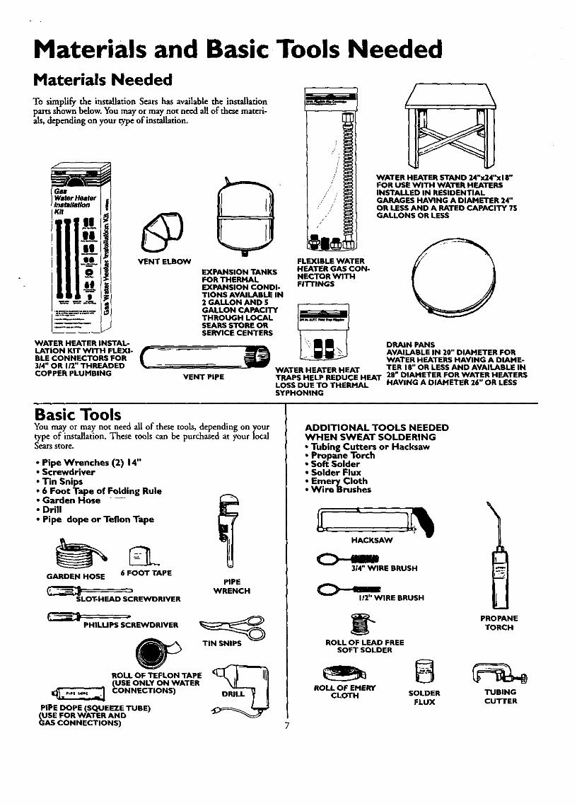
Materials and Basic Tools NeededMaterials NeededTo simplify the installation Sears has available the installationparts shown below. You may or may not need all of these mateti-als, depending on your type of installation.
WATER HEATER INSTAL-LATION KIT WITH FLEXI-BLE CONNECTORS FOR314" OR 112"THREADEDCOPPER PLUMBING
VENT ELBOW
EXPANSION TANKSFOR THERMALEXPANSION CONDI-TIONS AVAILABLE IN2 GALLON AND 5GALLON CAPACITYTHROUGH LOCALSEARS STORE ORSERVICE CENTERS
FLEXIBLE WATERHEATER GAS CON-NECTOR WITHFITTINGS
VENT PIPE
WATER HEATER STAND 24"x24"xl E"FOR USE WITH WATER HEATERSINSTALLED IN RESIDENTIALGARAGES HAVING A DIAMETER 24"OR LESS AND A RATED CAPACITY ?SGALLONS OR LESS
ODRAIN PANSAVAILABLE IN 20" DIAMETER FORWATER HEATERS HAVING A DIAHE-
WATER HEATER HEAT TER 18" OR LESS AND AVAILABLE INTRAPS HELP REDUCE HEAT 28" DIAMETER FOR WATER HEATERSLOSS DUE TO THERMAL HAVING A DIAMETER 26" OR LESSSYPHONING
Basic ToolsYou may or may not need all of these tools, depending on yourtype of installation. These tools can be purchased at your localSears store.
• Pipe Wrenches (2) 14"• Screwdriver
• Tin Snips• 6 Foot Tape of Folding Rule• Garden Hose ......• Drill
• Pipe dope or Teflon Tape
GARDEN HOSE 6 FOOT TAPE
SLOT-HEAD SCREWDRIVER
PHILLIPS SCREWDRIVER
ROLL OF TEFLON TAPE(USE ONLY ON WATER
CONNECTIONS)
PIPE DOPE (SQUEEZE TUBE)(USE FOR WATER ANDGAS CONNECTIONS)
PIPEWRENCH
TIN SNIPS
ADDITIONAL TOOLS NEEDEDWHEN SWEAT SOLDERING• Tubing Cutters or Hacksaw• Propane Torch• Soft Solder• Solder Flux• Emery Cloth• Wire Brushes
HACKSAW
314" WIRE BRUSH
112" WIRE BRUSH
ROLL OF LEAD FREESOFT SOLDER
PROPANETORCH
ROLL OF EPIERVCLOTH SOLDER TUBING
FLUX CUTTER

Installation InstructionsRemoving the Old Water Heater
Turn _OFF _ the gas supply to the water heater.
AWARNING . IIf the main gas line shutoff serving all _ apphancesis Iused,alsoshut "OFF" the gas at each appliance.Leave allgasappliancesshut "OFF" until the water heater installa-
tion iscomplete.
(_)Turn "OFF" the water to the water_" heater. Some installations require that
the water be turned off to the entirehouse.
Q Check again to make sure the gas supplyis "OFF _ to the water heater. Then dis-connect the gas supply connection fromthe gas control valve,
Q Attach hose thc,.water heater draina to
valve and put the other end in a floordrain or outdoors. Open the waterheater drain valve. Open a nearby hotwater faucet which will relieve pressurein the water heater and speed draining.
®
Disconnect the vent pipe from the draft hood wherethey connect to the water heater. In most installationsthe vent pipe can be lifted off after any screw or otherattached devices are removed. Dispose of the drafthood. The new water heater has the draft hood whichmust be used for proper operation.
a. If you have copper piping to the waterheater, the two copper water pipes canbe cut with a hacksaw approximately 4"away from where they connect to thewater heater. This will avoid cutting offthe pipes too short. Additional cuts canbe made later if necessary. Disconnectthe temperature-pressure relief valve
O drain line. When the water heater isdrained, disconnect the hose from thedrain valve. Close the drain valve. Thewater heater is now completely discon-nected and ready to be removed.
b. you pipe to waterIf have theheater, loosen the two galvanized pipeswith a pipe wrench at the union in eachline. Also disconnect the piping remain-ing to the water heater. These piecesshould be saved since they may be need-ed when reconnecting the new waterheater. Disconnect the temperature-pres-sure relief valve drain line. When thewater heater is drained, disconnect thehose from the drain valve. Close thedrain valve. The water heater is nowcompletely disconnected and ready to beremoved.
I AWARNING ]The water passingout of the drainvalve may he extremely ]hot. To avoid beingscalded,make sure all connectionsare ]tight _nd that the water flow is directed away from any [person.
ACAUTIONMineral buildupor sediment may haveaccumulated in theold water heater. This causesthe water heater to he muchheavier than normal and this residue, if spilled out, couldJcausestaining.

Installation Instructions (cont'd)Facts to Consider About theLocationWhether replacing an old water heater or putting the waterheater in a new location, the following critical points must beobserved.
This mobile home gas-fired water heater is for use in a mobilehome. You should carefully choose an indoor location for thenew water heater, because the placement is a very importantconsideration for the safety of the occupants in the buildingand for the most economical use of the appfiance. This waterheater is for.use only in mobile homes and is not intendedfor outdoor installation.
INSTALLATION METHOD B: An optional enclosureincorporating a solid exterior accessdoor, when a 5 or 8 diame-ter, or 20 square inch minimum equivalent fv:e air opening islocated in the floor of the enclosure. The opening must be cov-
i n •ered by a /4 wire mesh.
ENCLOSURE INSTALLATIONS:
The installation of this water heater must be within an
endoenre so .as to separate the a]ppliance combustion sys-tem and ventmg system from the interior atmosphere of the
. mobile home. There shall not be any door, removable.access panel, or oth.er opening into the enclosure from theinside of the mobsle home. This water heater must beinstalled using Method A or B.
INSTALLATION METHOD _ An endosure with an exte-rior access door incorporating a single opening positioned amaximum of 6" above the lower edge of-the access door andwhich may incorporate either '/4"wire mesh or louvers. When%"wire mesh is used, the size of the opening must be a mini-mum of 20 square inches. When the louvers are used, the areamust be a minimum of 20 square inches.
HOTWATEROUTLET
GASSUPPLY
ou'rSIDEWALt.OF
MOraLEHOME
MOUNTING
SOLIDEXTSRIORDOOR OF
t40_LE HOME
MESH
HOT WATER
GASSUPPLY
OUTSIDEWALL OF_IO_LEHOME
MOUNTINGBRACKETS
6" I
INSTALLATION IN ENCLOSURE OF MOBILE HOMEWITH LOUVERED EXTERIOR DOOR
INSTALLATION IN ENCLOSURE OF MOBILE HOMEWITH SOLID EXTERIOR DOOR
Install water heater into closet so as to have 1" minimum dear-ance at sides and back. Clearance of 4" is needed to front toaccommodate the gas control valve. Be sure to allow adequatedearance for servicing the water heater and for access to the pip-ing and temperature-pressure relief valve.
NOTE: DOOR MUST BEON OUTSIDE WALLOF MOBILE HOME.
I" MIN I ° MIN.
I* MIN,
4"MIkL
INSTALLATION CLEARANCES TOP VIEVV
9

Installation Instructions (cont'd)Facts to Consider About theLocation (cont'd)
A WARIqlNGMinimum clearancesbetween the water heater and com-bustibleconstructionare I" at the sidesand rear, 4" at thefront,and6" fromthe vantpipe.Clearancefromthe tep oftbejacketis 12"onmostmodeb.Notethat a lesserdi_ maybe allowedon somemodels Referto the label on the waterheateradjacentto thegascontrolvalveforall deeranc_
The water heater should be secured to the floor and to the wall
of the enclosure with th,,e,mounting brackets provided. Forbracket location refer to Securing Water Heater to Floor andWall' in the "Installation Instruct'ons" section.
When a mobile home is skirted, an air intake opening with aminimum free areaof 32 square inches must be provided in theskirt. If the opening is covered by louvers or screen, the total free
. area must be 32 square inches. Other gas fired appliances in thehome will require additional free air openings; consult thesemanufacturers for correct sizing.
AWARNING
A gaswater heatercannotope...rate_ wi_out _e cor-rect amountof air forcombast_n.Do not mstailin a confinedarea sucha closet,unlessyouprovideair asshown in the "Factsto ConsiderAbout the Location"soc_on on page9. Neverobstructthe flow of ventilationair. If you haveanydoubtsorquestionsat all, callyour gascompanyor SearsServiceCenter,Failureto providethe proper amount of combustionair canresult in a fire or explosionand cancauseDEATH, SERIOUSBODILYIN)URn,OR PROPERTYDAMAGE.
&WARNINGWhen the systemrequireswater at temperatureshigherthanrequiredfor other uses,the hot water systemmay requireameanssuchas a mixing valveto be installed to temper thewater at certainpointsof use.Somepeopleare more likelytobe permanentlyinjuredbyhotwater than others;these indudethe elderly,children,_e !nfirm, or the physically/mentailyhand-icapped.Beforeimmersingyourselforanyoneelseinhotwater,be sure to checkthe water temperature. WARNING: HOT-TER WATER INCREASES THE RISK OF SCALD INJURY.!(Alsosee"Temperature Regulation"section)Mixingvalvesareavailable.atplumbingsupplyor hardwarestere_ Followmanu-'facturersinstructions for installationof thesevalves. !
_,WARNING IThis water heater shai_ected to anyheatingays-Iternsor compenent(s)previouslyusedwitha nonpotablewater Iheatingappliance. I
AWARNING
If this water heaterwill be usedin beautyshops,barbershops,cleaning establishments,or self-servicelaundrieswith drycleaningequipment,it is imperativethat the water h_J.er orwater heatersbe installedso that combustionandven_la_onair be takenfrom outsidethese area_ Refer to the "Facts toConsiderAbout the Location"sectionof this manualandalsothelatost edition ofthe NationalFuelGasCede, ANSI Z223.1,also referredto as NFPA 54 for specificsprovidedconcerningair required.
10
I . AWARNING IToxicchemicalssuchas usedfor treatment of.b.oi.'lersor non-Jpotablewaterbeing appliancesshallneverbe,ntreducedintoIa potablewater beatlngsystem. I
&CAUTIONWATER HEATERSEVENTUALLY LEAK: Installationof the
w'_or beater mint be _o_mpllsbed in sucha manner_t.lfthe tankor any coanect_m shouldleak,the flowof water wdlnot causedamageto the structure.When suchlocationscan-not be avoided,a suitabledrain pan shouldbe installedunderthe water heater,Drain pansare availableat your localSoarsstore. Such a drain panmust be not greaterthan 1½inchesdeep,havea minimumlengthandwidth of at least 2 inchesgreater than the water heater dimensionsandmust be pipedto an adequatedrain.Thepanmustnotrestrictcombustionairflow.Underno circumstancesis the rnanufac_reror Searstobe held liablefor anywater damagein connectionwith thiswater heater.
When a drain pan is required, the installation must conform to"Method A" on page 9.
AWARNINGINSTALLATIONSIN AREASWHERE FLAMMABLELIQUIDS I(VAPORS) ARE LIKELY TO BE PRESENT OR STORED(GARAGES, STORAGE, AND UTILITY AREAS, ETC):Flammableliquids(suchas gasoline,solvents,propane(LP) orbutane, etc.), all of which emit flammable vapors,may beimproperlystoredor usedinsucharea_ The gaswater heaterpilot lightor main burnercan ignitesuchvapor_The resultingflashbackandfirecancausedeathor seriousbumsto anyoneinthe area,aswellaspropertydamage.If installationin suchareasisyour onlyoption,then the installa-tion must be accomplishedin a waythat the pilot flame andmainburnerflameare elevatedfromthe floorat least18inches.While this mayreducethe changesof flammablevaporsfromafloorspillbeingignited,gasolineandotherflammablesubstancesshould neverbe storedor usedin the sameroom or area con-_ining a gaswater heateror otheropenflameor sparkpnxluc-mgapplianc_NOTE: Flammablevaporsmaybe drawnby air currentsfromotherareasof the structureto tbe apprmnce.
AWARNINGPropellantsof anrosol spraysand volatilecompounds,(clean-ers,chlorine basedchemicals,rofHgerant_etc.) in additiontobeinghighlyflammableinmanyc_ses_will alsochangeto cor-rosivehydrochloricacid when exposedto the combustionproductsof the water heater.The resultscan be hazardomandalso causeproductfailure.
AWARNING
This water heater must not be installeddirectlyon carpeting.Carpeting must be protected by a metal or wood panelbeneath the applianceextendingbeyond the full width anddepth of the appliance by at least 3 inches(76.2mm) in anydirection,or if the applianceis installedin an alcoveor closet,the entire floormust be coveredby the panel.Failureto heedthis warningmayresultinafire hazard.
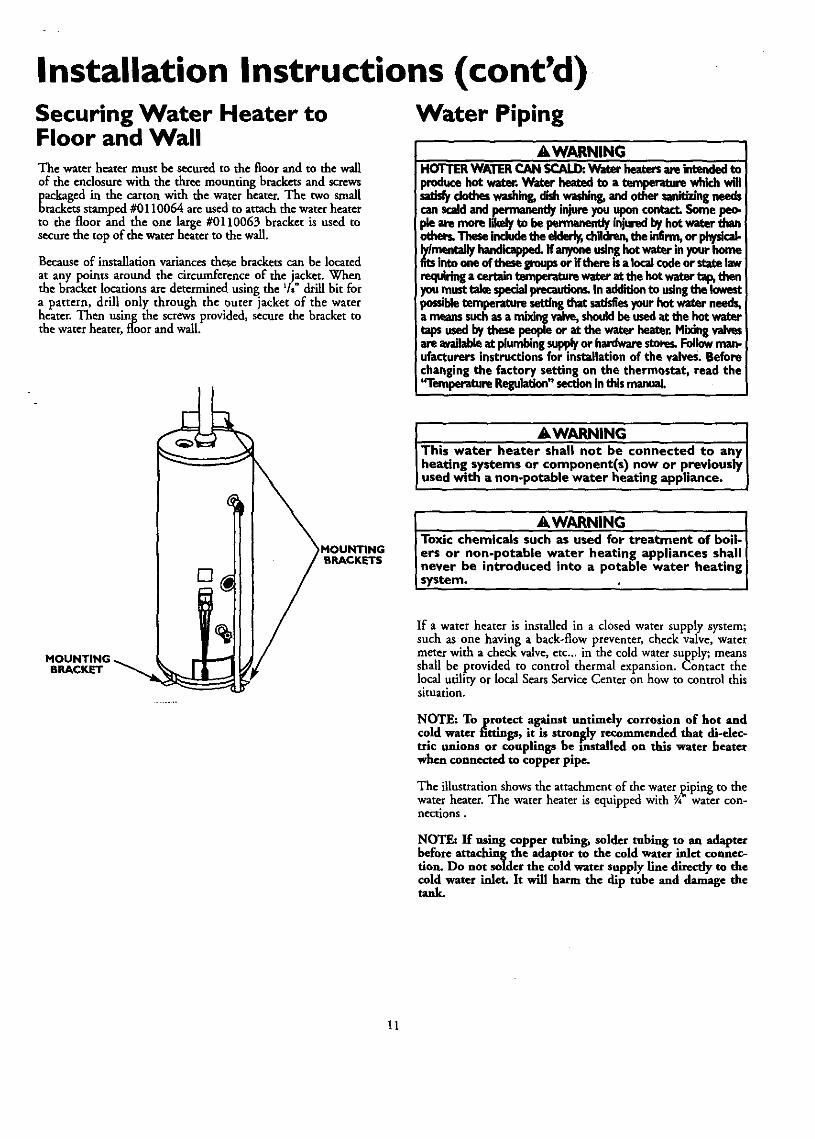
Installation Instructions (cont'd)Securing Water Heater toFloor and WallThe water heater must be secured to the floor and to the wallof the enclosure with the three mounting brackets and screwspackaged in the carton with the water heater. The two smallbrackets stamped #0110064 are used to attach the water heaterto the floor and the one large #0110063 bracket is used tosecure the top of the water heater to the wall.
Because of installation variances these brackets can be located
at any points around the circumference of the jacket. Whenthe bracket locations are determined using the % drill bit fora pattern, drill only through the outer jacket of the waterheater. Then using the screws provided, secure the bracket tothe water heater, floor and wall.
Water Piping
AWARNINGHOTTERWATERCAN SCALDtWater heatersare intendedto
_hce hotwatt. Waterhea_., to a temperaturewhh..hva'lldotheswashing,dishwadain_and othersanitizingneeds
canscaldand pennanen_ injureyouuponcontact.Somepeo-
othe_ Thesemdudethe eldor_ chHdre_the inErm,or physical-lylm_mlallyhandicapped.If anyoneusinghotwaterinyourhomefitsintooneof theseiFoupsor ifthereisa localcodeorsta_ lawrequiringa certaintern.peretumwaterat the hotwaterta_ thenyoumust takespecialprecaution_In add'_ionto usingthe lowestpotabletemperature,setting_aat_ yourhotwater needga meansinch asa mi_ng valve,shouldbeusedat the hot watertapsusedbythesepeopleor at the water heat_r.Mixlngvalvesare availableat plumbingsupplyor hardwarestore_Followman-ufacturersinstructionsfor installationof the valves.Beforechangingthe factory setting on the thermostat, read the'q'emperetureRegulation"sectioninthismanual
MOUNTING,BRACKET
)MOUNTINGBRACKETS
AWARNING]This water heater shall not be connected to anyI heating systems or component(s) now or previouslyI used with a non-potable water heating appliance.
- AWARNING . IToxic chemicals such as used for treatment of bod-ers or non-potable water heating applmnces shallnever be introduced into a potable water heating isystem. ' i
If a water heater is installed in a closed water supply system;such as one having a back-flow preventer, check valve, watermeter with a check valve, etc.., in the cold water supply; meansshall be provided to control thermal expansion. Contact thelocal utility or local Sears Service Center on how to control thissituation.
NOTE: To protect against untimely corrosion of hot and
cold water fittings, it is strongly recommended that di-elec-trlc unions or couplings be installed on this water heaterwhen connected to copper pipe.
The illustration shows the attachment of the waterpiping to thewater heater. The water heater is equipped with 3A"water con-nections.
NOTE: If using copper tubing, solder tubing to an adapterbefore attaching the adaptor to the cold water inlet connec-tion. Do not solder the cold water supply line directly to thecold water inlet. It will harm the dip tube and damage thetank.
11

Installation Instructions (cont'd)Water Piping (cont'd)• Look at the top cover of the water heater. The water outlet is
marked hot. Put two or three turns of teflon tape around thethreaded end of the threaded-to-sweat coupling and aroundboth ends of the ¾ threaded nipple. Using flexible connec-tors, connect the hot water pipe to the hot water outlet of thewater heater.
• Look at the lower fight side of the water heater. The coldwater inlet is marked cold. Put two or three turns of teflontape around the threaded end of the threaded-to-sweat cou-pling and around both ends of the _A"threaded nipple. Usingflexible connectors, connect the cold water pipe to the coldwater inlet of the water heater.
WATER PIPING PRESSURE TEST
This section isonly for the mobile home manufacturerinstallingthe water heater when the installation is to comply with H.U.D.Standards.
When testing the water ways, H.U.D. Standards state:"Water distribution system. All water piping in the water dis-tribution system shall be subjected to a pressure test. The testshaft be made by subjecting the system to air or water at 100psi for 15 minutes without loss of ptessure. When air pres-sure is used, the water heater shall not be connected dur-hag the test."
NOTE: This water heater is insulated to minimize heat lossficom the tank. Further reduction in heat loss can be accom-
plished by insulating the hot water lines from the water_ttero
INSTALLATION COMPLETED USINGSEARS INSTALLATION KIT
HO3" OUTL_t_
TO HOUSE/
THREADED TOSWEAT COUPLING
CONNECTOR
PRESSURERELIEF VALVE
THREADED TOSWEAT COUPLING
FLEXIBLE WATER
shutoff
COLD INLETWATER LINE
314" THREADED_COUPLINGS
&WARNING
If the water piping system is to be air pressure test.ed, the water heater must be disconnected fromthe water piping system. Failure to disconnect thewater heater during air pressure testing of thewater piping system could result IN DEATH, SERI-OUS BODILY INJURY, OR PROPERTY DAMAGE.
HOT OUTLET
WHEN AIR TESTING,REMOVE THE WATER
LINES FROM THEWATER HEATER
COLD INLET
(Do not cap or plug.Must terminate beneath
Mobile Home)
12
Installation Instructions (cont'd)Temperature.Pressure Relief Valve
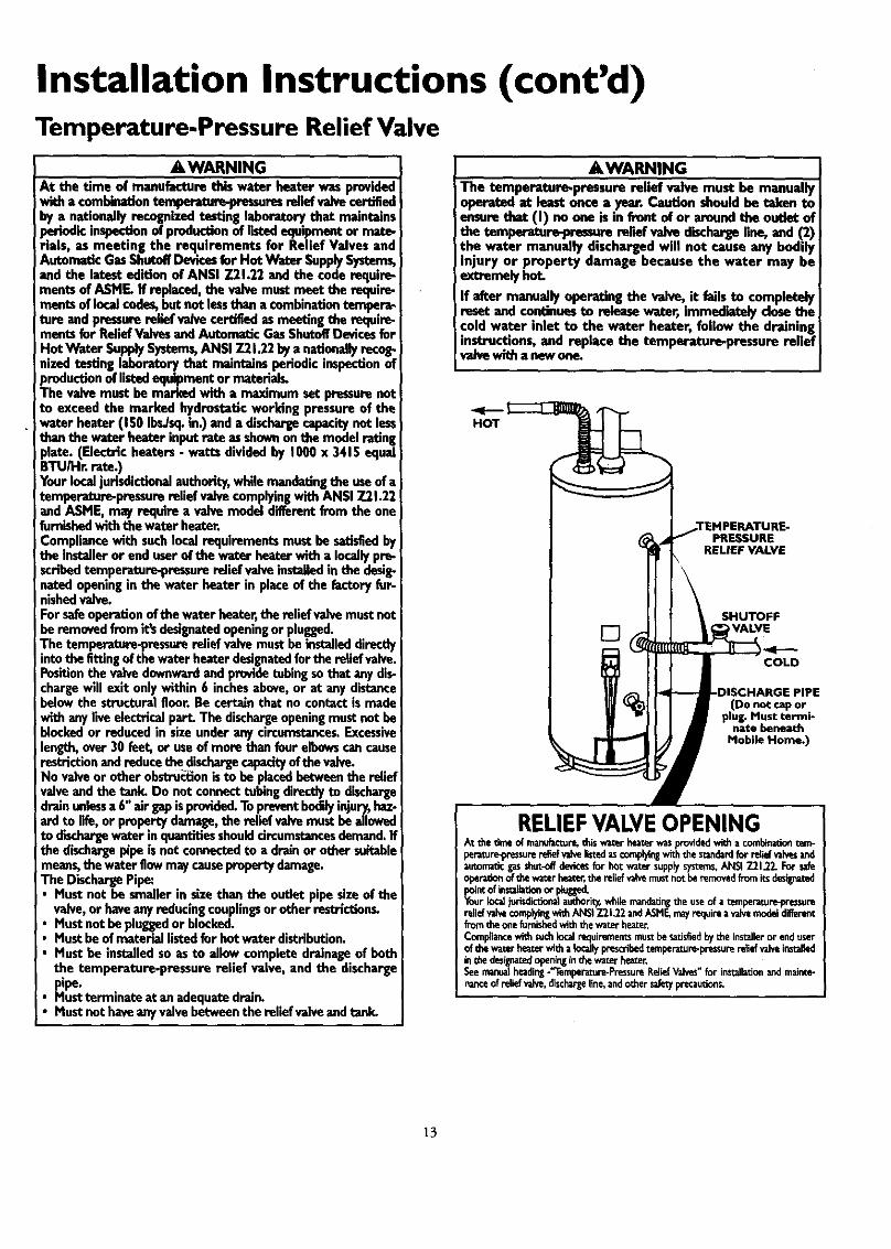
AWARNINGAt the time of manufacture this water heater was providedwitha combinationtomperature-prassuresreliefvalvecertifiedby a nationallyrecognizedtesting laboratorythat maintainsperiodicinspectionof productionof listedequipmentor mute-rials, as meeting the requirements for Relief Valves andAutomaticGasShutoff Devicesfor Hot Water SupplySystems,and the latest edition ef ANSI 7.21.22and the coderequire-ments ef ASME. If replaced, the valvemustmeet the requir_rnents ef localcedes,but not lessthana combinationtempera.tore andpressurerelief valvecertifiedasmeeting the require-meritsfor ReliefValvesandAutomaticGasShutoffDevicesforHot Water SupplySystems,ANSI 7.21.22bya nationallyrecog-nized testinglaboratorythat maintains periodicinspec_onofproductionoflistedequipment,or meterl:als,The valvemust be markedwith a rna_mum setpressurenotto exceed the marked hydrostaticworking pressureof thewater heater (150II_/sq. in.) anda dischargecapacitynot lessthanthe water heater inputrate ..asshownon the modelratingplate. (Electric heaters- watts drvidedby 1000x 3415 equalBTU/Hr. rate.)Yourlocaljurisdictionalauthority,whilemandatingthe useof atemperature-pressurerelief valvecomplyingwith ANSI 7.21.22and ASME, may requirea valvemodel diiferentfrom the onefurnishedwith the waterheater.Compliancewith suchlocalrequirementsmustbe satisfiedbythe installeror enduserof the water heaterwith a locallypre-scribed temperature-pressurerelief valveinstalledinthe desig-natedopeningin the water heater in placeof the factoryfur-nishedvalve.For safeoperationofthe water heater,the relief valvemustnotbe removed fromit'sdesignatedopeningorplugged.The tempe.ratere-pressorerelief valvemustbe installeddirectlyintothe fittingof thewater heaterdesignatedforthe re,el valve.Position the valvedownwardandprovidetubing sothat any dis-!chargewill exit onlywithin6 inchesabove,or at anydistancebelowthe structuralfloor.Be certainthat no contactis madeIwith anyliveelectricalpart. The dischargeopeningmustnotbeblockedor reduced in sizeunderany circumstances.Excessivelength,over 30 feet, or useof more than fourelbowscancauserestriction andreducethe dischargecapacityofthe valve.No valveor otherobstru_ionis to be placedbetweenthe reliefvalveand the tank. Do not connecttubing directlyto dischargedrainunlessa 6"air gapisprovided.Topreventbodilyinjury,has-arclto life,or propertydamage,the relief valvemustbeallowedto dischargewater inquantitiesshouldcircumstancesdemand.Ifthe dischargepipeis notconnectedto a drainor othersuitablemeans,the waterflowmaycausepropertydamage.The DischargePipe:
Mustnot be smallerin sizethan the outlet pipesizeof thevalve,or haveanyreducingcouplingsorother restrictions,Mustnot be pluggedor blocked.Mustbeof materiallistedfor hotwater distribution.Mustbe installedso asto allowcompletedrainageof beththe temperature-pressure relief valve, and the dischargepipe.Mustterminateat anadequatedrain.
• Mustnothaveanyvalvebetweenthe relief valveandtank.
AWARNINGThe temperature-pressure relief valve must be manuallyoperated ut least once a year. Caution shouldbe taben toensurethat (I) noone is in front ef or aroundthe outfot of
!the temper_ure-peessurereliefvalve dischargeline, and (2)the water manually dischargedwill not causeany bodilynjury or property damage because the water may be
iextremelyhot
If after manually operating the valve, it failsto completelyireset and continuesto releasewater, immediatelydose thecold water inlet to the water heater, follow the draininginstructions,and replace the temperature-pressure reliefvalvewltha newone.
,TEMPERATURE-PRESSURE
RELIEF VALVE
SHUTOFF
[] VALVE
I COLD
PIPE(Do not cap or
plug. Must termi-nate beneath
Mobile Home.)
RELIEFVALVEOPENINGAt thetimeof manufacture,thiswaterheaterwasproddedwitha combinationtem-pe_tur_pressurereliefvahelistedascomplyingwiththe standardfor re,el _ andautomaticgasshot-offdevice_for hot wa_r supplysy_erns,ANSi791.22.For safeoperationofthewaterhe_t_ thereliefvalvemustnotbe removedfromitsdasillna_pointofinstaiLatfunor p_ed.YourIo_ judsdictfunalauthori_whilemandatir_the useof a temperature-pressurereliefvalvecomplyingwithANSI7.21.22andASMF_mayrequireavalvemodeldifferentfromtheonefurnishedwith thewaterheaterCompliancewithsuchfucalrequirementsmustbesatisfiedby the installeror enduserof thewaterheaterwitha locallyprescribedtempe_ture-pressurerellef_ahein_l_inthedesignat_openinginthewaterheater.Seemanualbeadin_-'Temperatu_*PressureP,eliefVahes for in_llationandmainte-nanceof relie_valve,dischargeline,andothersafe_precau_ons.
13

Installation Instructions (cont'd)Filling the Water Heater
A CAUTION INeverusethiswator heetor unlessit B compietaiyfilled with Jweter.To proventdamageto tbe tank,the tank m_-t betiltedJwith water. Water must flow from the hot water faucetbeforeturning "ON" gasto the water heator. I
To fill the water heater with water:• Close the water heater drain valve by turning the handle to
the right (clockwise). The drain valve is on the lower front ofthe water heater.
• Oip_e cold water supply valve to the water heater.NOTE, The cold water supply valve must be left openwhen the water heater is in us_
• To insure complete filling of the tank, allow air to exit byopening the nearest hot water faucet. Allow water to rununtil a constant flow is obtained. This will let air out of thewater heater and the piping.
• Check all new water piping for leaks. Repairasneeded.
Venting• Place the draft hood legs in the receiving holes on the top of
the water heater. The legs will snap in the holes to give ativ.ht fit.
• P['ace the vent pipe over the draft hood. With the vent pipein position, drill a small hole through both the vent pipe anddraft hood. Secure them together with a sheet metal screw.
DRAFT HOOD INSTALLATION
DRAFT HOOD t
A/VENT . I;
/ VENT TO j !__L____ENi CAF
J=_ OUT-DP_ET • _ DOORSOR _ _---ROOFJACKHOOD CHIMNEY _;
AWARNINGVENT DAMPERS - Any vent damper, whether it isoperated thermally or otherwise must be removed if itsuse inhibitsproper drafting of the water heater.Thermally Operated Vent Dampers: Gas-fired waterheaters having thermal efficiency in excessof 80% may)roduce a relatively low flue gas temperature. Such
temperatures may not be high enough to properly openthermally operated vent dampers. Thes would causespillage of flue gases and may cause carbon monoxidepoisoning.Vent dampers must bear evidence of certification ascomplying with the latest edition of the AmericanNational Standard ANSI Z21.68 (ANSI Z21.66 & 67,respectively, cover electrically and mechanically actuat.ed vent dampers). Before installation of any ventdamper, consult the local Sears Service Center or gasutility for further information.
AWARNINGTo insureproper ventingof this gas-firedwater heater, thecorrectvent pipediameter mustbe utilized.Anyadditions ordeledom ofother gasapplianceson acommon vent with thisw-aterbeator may_ affect the operationof the weterheater.Consultthe localSearsServiceCanter or gasu_lity ifany,uchchangesaropkmn L
Check the venting system for signs of obstructionor deteriorationand replace if needed.
The combustion and ventilationair flow mustnot be obstructed.
&WARNINGThe water heaterwith draft hoodinstalledmustbe properlyventedto a chimneywhichterminatesoutdoorLNever oper-atethe watsr heaterunlessit isventedto the outdoorsand hasadequateair su.p_yto avoidrisksofimproperoperation,explo-sionor asphyxiat_
• &WARNINGObstructedor deterioratedventsystemsmaypresenta senousJ
healthriskor_. I
All vent gases must be completely vented to the outdoors of thestructure (dwe!ling). Insrall only the draft hood provided withthe new water heater and"no other draft hood.
Vent pipes must be secured at each joint with sheet metal screws.
The water heater must be connected to a roof iack: The ventpipe from the water heater to the roof jack must be no less thanthe diameter of the draft hood outlet (min. Y') on the waterheater.
This water heater may be installed with single wall or Type Bvent pipe connection to the draft hood and the following U.L.listed roof jacks not furnished.
Triangle Products No. 773-50Vent Line No. 2073Strawsine No. 73TWhite Metal Products 3RJ
There must be a minimum clearance of 12" between the top ofthe draft hood and the top of the enclosure.The draft hood and combustion air inlet to the water heatermust be in the same atmospheric pressure zone. Do not separateby a wal!, shelf, ceiling, partition, or any other means.
AWARNING
Failure to have required clearances between ventpiping and combustible material will result in a firehazard.
. AWARNING JBe sure vent pepe is properly connected to preventescapeof dangerousflue gaseswhich could causedeadlyasphyxiation.
14

Installation Instructions (cont'd)Venting (cont'd)
AWARNING
Chemical vapor corrosion of the flue and vent systemmay occur if air for combustion containscertain chemlcaivapors.Spraycan propellants,cleaningsolvents, refrigera-tor and air conditioner refrigerants, swimming poolchemicals, calcium and sodium chloride, waxes bleachand process chemicals are typical compoundswhich arepotenti=lly corrosive.
Gas Piping
AWARNINGMake surethe gassuppliedis the same type listed on the
i model rating plate. The inlet gaspressuremust not exceed14 incheswater column ½ poundper squareinch (3.5kPa).
iThe minimum inlet gaspressurelistedon the model rating
j plateisfor the purposeof inputadjustment.
_WARNINGIf the gascontrolvalve issubjected to pressuresexceeding ½Ipound per square inch(3.5klPa),the damageto the gascon-tro valvecouldresult n afireor explosionfrom leakingga_
AWARNING
If the main gasline shutoff servingall gasappliancesis used,alsoturn "OFF" the gasat eachappliance.Leaveallgasappli-ancesshutoffuntil the water heater installationiscomplete.
&WARNINGThe applianceand its gas connectionmust be leak testedbeforeplacingthe appliancemoperation.
&WARNING• The applianceandits individualshutoffvalvemustbe discon-nect_ fromthe gassupplypipingsystemduringany pressuretesting of the gassystemat test pressuresm excessof
persq=r*inch(3.Skh).•Tbe appliancemustbe isolatedfromthe gassupplypipingsys-tem by dosingi_ individualmanualshutoff valveduringpressuretestingof the gassupplypipingsystemat testpres-suresequalor lessthan'/2poundpersquareinch(].SkPa).
AWARNING IUse pipe joint compoundor teflon tape marked as beingJ
Lresistantto the actionof petm eum let°pane (LR)] gases" ...J
A gas line of sufficient size must be run to the water heater.Consult the latest edition of National Fuel Gas Code ANSIZ223.1 also referred to _ NFPA54 and the gas company concern-ing pipe size,
There must be:
I A readily accessiblemanual shut off valve in the gas supply lineserving the water heater, andA drip leg (sediment trap) aheadof the gas control valve to helpprevent dirt and foreign materials from entering the gas controlValve,
• A flexible gas connector or a ground joint union between theshutoffvalve and control valve to permit servicing of the unit.
Be sure to check all the gas piping for leaks before lighting thewater beater. Use a soapy water solution, not a match or openflame. Rinse offsoapy solution and wipe dry.
SEDIMENT TRAP
A sediment trap shall be installed as close to the inlet of thewater heater as practical at the time of water heater installation.The sediment trap shall be either a tee fitting with a capped nip-ple in the bottom outlet or other device recognized as an effec-tive sediment trap. If a tee fitting is used, it shall be installed inconformance with one of the methods of installation shownbelow.
GAS PIPING WITHFLEXIBLE CONNECTOR
_H, GAS SUPPLYPIPING
MANUALSHUTOFF
VALVEFLEXIBLEGAS CONNECTOR
LABELED AS COMPLYING
WITH ANSI STANDING
GROUND
GASCONTROL
VALVE
AWARNING
Contaminants in the gasfinesmaycauseimproperoperationof the gas controlvalvethat may resultin Ere or explosion.Beforeattachingthe gaslinebe surethat allgaspipeiscleanon the inside.To trap anydirt or foreignmaterial in the gassupplyllne, a drip leg (sometimescalled a sediment trap)mu_ be incorporated in the piping.The drip leg must bereadilyaccessible.Installinaccordancewith the "Gas Piping"section.Referto the latest editionof the Na_onal Fuel GasCede, ANSI 7.223.1,also referredto asNFPA 54.
15

Installation Instructions (cont'd)"Fuel" Conversion Instruc-tions From Natural Gas ToPropane (L.P.) Gas
&WARNINGThis water heater has been factory equipped to operatewith the type gasindicated in the "EQUIPPED FOR" areaof the model rating plate located near the gas controlvalve. The indicated gas may be either Natural orPropane (L.R). By following the conversioninstructionsinthis manual or the instructions near the gascontrol valve,the water heater must be converted if it is to be usedwith the opposite gas. DO NOT USE THIS WATERHEATER WITH ANY GAS OTHER THAN THE ONELISTED ON THE MODEL RATING PLATE. Failure to usethe correct gas can cause problems which can result inDEATH, SERIOUS BODILY INJURY, OR PROPERTYDAMAGE. If you have any questions or doubts consultyour gassupplieror gas company.
Read and follow detailed conversion instructions located on thewater heater and also in this manual in their entirety before startingthe conversion.
Conversion kit with necessary parts are in a bag attached to thedrain valve.
Step 1.
Step 2.
Step 3.
Step 4.
Step 5.
Turn gascontrol knob "A"to "PILOT". Depress and turn"OFF. (See Figure 1, page 17).
Remove outer and inner access doors from water heater.
Removeburner as_,mbly from water heater and control byloosening _Anut H holding burner assembly to control.(See Figure 2, page 17). Loosen pilot tube nut _J" andthermocouple nut "K" at control.
Remove screws _D" disengaging manifold from burner.(See Figure 3, page 17)
Remove orifice _E" (See Figure 3, page 17) using 3A"wrench. Install orifice marked _L.P." found in the baginto manifold. Tighten securely. Secure burner to mani-fold with screwsSD ' .
Step 6. Loosen pilot tube nut "F" (See Figure 4, page 17). Re-move orifice "G" and replace with blue colored orificefound in bag. Reinstall nut "F" and tighten securely.
Step 7. Makesure all connections are tightened securely,and rein-stall burner assemblyinto waterheater. Position end of themanifold inside bracket as shown in Figure3 on page 17.Reinstall manifold into control and tighten 3A"nut ("H')securely. Recheck to see that end of tuanifold is still insidebracket as shown in Figure 3 on page 17. Reinstall pilottubing and thermocouple into control. (See Figure 2,page 17)
Step 8. Place screwdriver in slot _B'. (See Figure 1, page 17). De-press and turn counter-clockwise (_-'_) to stop. Con-trol screw must be in "IN" position for propane (UE) gasand m OUT posmon for natural gas. STOP. Read label"For Your Safety" located on your water heater.
Step 9.
Step 10.
Step 1I.
Step 12.
Step 13.
Step 14.
Step 15.
Step 16.
Step 17.
Step 18.
Step 19.
Set the thermostat to lowest settingby turning the water temperaturedial clockwise, ("-'_) to its lowesttemperature setting (with arrow ondial) asshown. DO NOT FORCE.
Turn gas control knob clockwise _ _ to _OF F_,._:_si-tion. Knob cannot be turned from PILOT" to OFF"unless knob is depressed slightly. DO NOT FORCE.
Wait five (5) minutes to dear out any gas. If you thensmell gas, STOP! Follow _B" in the safety informationon "ForYourSafety" label. If you don't smell gas, go tothe next step.
Find pilot-follow metal tube from gas control. The pilotis located on the right hand side of the burner. (See Fig-ure 4, page 17)
PILOT BURNER ___ THERMOCOUPLE
If you don't smell gas, turn knob on gas control
counter-clockwise __ to _PILOT" position.
Push in control knob all the way and hold down. Imme-diately light the pilot with a match. Continue to holdcontrol knob in for about one (1) minute after the pilotis lit. Releaseknob and it will pop back up. Pilot shouldremain lit. If it goes out, repeat steps 9 through 12.• If knob does not pop up when released, stop and
immediately call the Sears Service Center or gassupplier.
• If the pilot will not stay lit after several tries, depressand turn the gas control knob clock-
wise _ _ to "OFF"and call the Sears Service Cen-ter or gas supplier.
Check for gas leaks with only pilot flame burning usinga soapy water solution, not a match or open flame.Cbeck for gas leaks at fittings_F_and _G_ (SeeFigure4,page 17) and at fitting _J" (See Figure2, page 17).
Make sure temperature adjustment dial is turned dock-wise (f'-'%) in its lowest position (See Figure 1,page 17).
Replace inner and outer doors.
At arms length away turn gas control knob to the fullON position. WARNING: Do not use gas control
knob to regulate gas flow. Turn temperature adjust-tuent dial counter-clockwise (_"x) until gas flows tomain burner and ignites.
With a soapy water solution, not a match or openflame, check for gas leaks at gas connection "H'. (SeeFigure 2, page 17). If gas leak occurs, turn offimmedi-
ately by shutting offgas cock at inlet to/a,._control,or by turning gas control knob sh'_ to PI-LOT" pushing down and turning to "OFF ". Repair gasleak as necessary, and repeat steps 9 through 19.
16

Installation Instructions (cont'd)Step 20. At arm's length away,set the thermostat to desired set-
ting. The mark _ HOT indicative of approx. 120°F isLP,,referredstarting pint. If hotter water is desiredsee theTemperature Regulation section in this manual.
"A" (KNOB
AWARNINGHotter water increases the risk of scald inlury.Before changing temperature setting see the
"Temperature Regulation" section in this manual.
GASUNE
Step21. Replace the outer door ifnot replaced in step 17.
Step 22. Remove adhesive label found in conversion kit andplace next to the model rating plate. Mark label indi-cating for which type gas the water heater is nowequipped.
"Fuel" ConversionInstructions From Propane(L.P.) Gas To Natural Gas
TEMPERATURE it- PLASTICCAP
ADJ.DIAL ,,
"_--o_ _R NATURAL
[ Figure I ] IN FOP,PROPANE(LR)
AWARNINGThis water heater has been factory equipped to operatewith the type gasindicated in the "EQUIPPED FOR" areaof the model rating plate located near the gas controlvalve. The indicated gas may he either Natural orPropane (LR). By following the conversioninstructionsinthis manual or the instructionsnear the gascontrol valve,the water heater must he converted if it is to he usedwith the opposite gas. DO NOT USE THIS WATERHEATER WITH ANY GAS OTHER THAN THE ONELISTED ON THE MODEL RATING PLATE. Failure to usethe correct gas can cause problems which can result inDEATH, SERIOUS BODILY INJURY, OR PROPERTYDAMAGE. If you have any questions or doubts consultyour gas supplieror gascompany.
To convert from Propane (L.P.) gas to Natural gas, follow the"Fuel" Conversion Iristructions From the =Natural Gas toPropane (LP.) Gas" section except in Step 5, use orifice "E",marked "NAT.". In Step 6 use pilot orifice "G", brass color andin Step 8 turn control screw "B_"in Figure 1 clockwise (f-"%)to stop. Screw must be in "OUT" position for Natural gas.
See =Instruction Label" for orifice sizes.
Maximum Supply Pressure:14"W.C. For Nat. Gas.14" W.C. for Propane (L.E) Gas
Minimum Supply Pressure5" W.C. for Nat. Gas.11" W.C. For Propane (L.E) Gas
NOT "H"
THERHOCOUPLE ][ L_ LL PILOT TUBING
IF,guru2} N,FOLOBURNER
,PILOT TUBING'_ _
I Figure 41 "F"
17

Installation Instructions (cont'd)Installation ChecklistBEFORE LIGHTING THE PILOT:
• Check the gas lines for leaks._. Use a soapy water solution. DO NOT test for gas leaks
usinga match or open flame.b. Brush the soapy water solution on all gas pipes, joints and
fimngs.c. Check, for bubbling soap. This means you have a leak.
Turn OFF gas and make the necessary repairs.d. Recheck for leaks.e. Rinse offsoapy solution and wipe dry,
• Is the new temperature-pressnse relief valye properly installedand piped to an adequate drain? See Temperature-PressureReliefValve section.
• Are the cold and hot water lines connected to the waterheater correctly? See _Water Piping" instructions in the"Installation Instructions" section.
• Is the water heater completely filled with water. See Pi/hnginstructions in the "Installation Instructions _ section.
• Will a water leak damage anything? See the "Facts toConsider About the Locatio_ section.
• Is there proper dearance between the water heater and any-thing that might catch fire?See the "Facts to Consider Aboutthe Location" section.
• Do you have adequate ventilation so that the water heaterwill operate properly? See Combustion Air and Ventilationin the "Facts to Consider About the Location_ section.
Is the drafthood vent piping properly secured? See "Venting"instructions in the "Installation Instructions" section•
HOT
GASSUPPLY
SHUTOFFVALVE
DRIP LEG(Sediment trap)
PIPE CAP
VENT PIPE TO ULLISTED ROOF JACK
TEMPERATURE-PRES-SURE RELIEF VALVE
SHUTOFFVALVE
COLD COLD
DMonot cap or plus.ust terminate
beneathMobile Home.)
Is there proper clearance between the vent pipe and anythingthat might catch on fire_ See Venting instructions in the"Installation Instructions section•
• Is the vent pipe properlE sloped and does the vent terminateoutdoors? See "Venii_g" instructions in the "InstallationInstrucuons section,
• Do you need to call your gas company to check the gas pipeand its hookup?
MODEL RATING PLATE
18

Operating InstructionsLighting
AWARNINGBEFORE LIGHTING [PROPANE (L.R) GAS WATERHEATERS]:Propane(LR) gasisheav_ thanair, Shouldtherebe a leak in the system, the gaswill settle near the ground.Basements,crawlspaces,skirted areasunder mobile homes(evenwhenvenl_la_, dosutsandareasbelowgroundlev_ willserve as pockets for the accumulationof this gas. Beforeattemptingto ligl_,or relight_ water heater'spilotor turningon a nemaoyelectrlcalli_t_'€switch,beabsulutdysumthem isnoaccumulatedgasint_ are_ Searchfor odorof gasbym'dfingatgroundlevelinthe vicinityof tbe appliance.If odoris detected,followstepsindicatedat "For YourSafety"onthe coverpageofthismanualthenleavethe premises.
Lighting and operating instructions are located on front of thewater heater, above or to one side of the gas control valve.
Figure 5 ]
AWARNINGAN ODORANT ISADDED TO THE GAS USED
BY THIS WATER HEATER.FOR YOUR SAFETYIF YOU SMELl.GAS:
Do not try to lightany applie_.e.Do not touch anyelectrlcalswitch;do not useanyphoneinyour building.Immediatelycallyourgassupplierfrom aneighbor'sphone.Follow the gassuppliersinstructions.If you cannot reachyour gassupplier,call the fire depart.merit.
Figure 6 ]
AWARNINGDO NOT forcethe gascontrol knob.Use only your handtopushit downto light the pilot,or to turn it to "ON", "OFF"or "PILOT". Never usea tool suchasa lever,wrenchor pli-er_ Do not hit or damage the knob.A damagedknob mayresult in an explosionandseriousinjury,ffyou haveproblemturning the knob, callthe gassupplier immediately.
19
Figure 7 ]
I Figure 8 ]
INNER- ._DOOR
_ UTERDOOR
perating Instructions (cont'd)Lighting label on the water heater as it appears above the thermostat
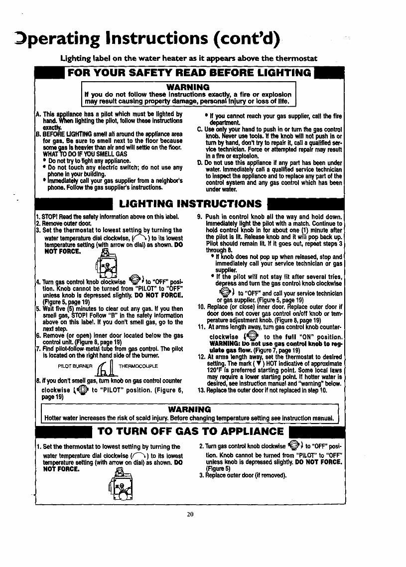
FOR YOUR SAFETY READ BEFORE LIGHTING
WARNING JIf you do not follow these Instructions exactly, a fire or explosionmay resu t causing property damage, personal njury or ose of life.
A. This appliancehas a pilot which mustbe lighted byhand.Whenlightingthe pilot,followtheseInstructionsexactly.
g. BEFORELIGHTINGsmellallaroundtheapplianceareafor gas. Be sure to smell next to the floor becausesomegas Is heavierthanairandwillsettleonthericer.WHATTO DOIFYOUSMELLGAS
eeeDonottry to lightanyappliance.Do not touch any electric switch; do not use anyphoneInyourbuilding.Immediatelycall yourgassupplierfroma neighbor'sphone.Followthe gassupplier'sinstructions.
• If youcannotreachyour gas supplier,cell the findepeth_nL
C. Use onlyyour handto pushin orturn the gascontrolknob.Neverusetools. If the knobwill notpushin orturn byhand,don_try to repairIf, calla qualifiedser-vice technician.Forceor attemptedrepairmay resultinatim orexplneion.
D. Donot use thisapplianceif anypart has beenunderwater.Immediatelycell a qualifiedservicetechnicianto inspecttheapplianceandto replaceanypart of thecentral systemand any gas controlwhichhas beenunderwater.
LIGHTING INSTRUCTIONS
1. STOPIReadthe safetyinformationaboveonthislabel.2. Removeouterdoor.3. Set the thermostat to lowest setting by turning the
watertemperaturedialclockwise,(F'_) to its lowesttemperaturesetting (witharrowon dial)asshown,DO
NOT FORCE,
4. Turngas centrul knobclockwise_J'* to "OFF" posi-tion. Knob cannot be turnedfrom "PILOT" to "OFF"unlessknob Is depressedslightly.DO NOT FORCE.(Fi(_lure5,page 19)
5. Wait five (5) minutesto clearout any gas. if you thensmellgas, STOP!Follow"B" in the safetyinformationaboveon this label If you don't smellgas, go to thenextstep.
6. Remove(or open) inner door locatedbelow the gascontrolunit. (Figure8, page19)
7. Rnd pilot-followinstaltubefromgascontrol Thepilots ocatedonthe r ghthands deof theburner.
PILOT BURNER ._THERMOCOUPLE
8, Ifyoudon1smellgas,turnknobongascontrolcounter
clockwise _@ to "PILOT" position. (Figure 6,page19)
9. Push in control knob all the way and hold down.Immediatelylightthe pilotwitha match.Continuetoholdcontrol knob in for about one (1) minuteafterthe pilot is lit. Releaseknoband it will pop backup.Pilot shouldremainlit. If it goesout, repeat steps3through8.
• If knobdoesnotpop upwhen released,stopandimmediatelycall your servicetechnicianor gassupplier.
• If the pilot will not stay lit after several tries,depressandturnthe gas controlknobclockwise
_) to "OFF" andcallyourservicetechnicianorgassupplier.(Figure5, page19)
10. Replace(or close) innerdoor. Replaceouter doorifdoordoesnot covergas controlon/offknobor tem-peratureadjustmentknob.(Figure8, page19)
11. At armslengthaway,turngas controlknobcounter-
clockwise _ to the full "ON" position,WARNING: Do not use gas control knob to reg.ulate gas flow. (Figure7, page19)
12. At arms lengthaway,setthe thermostatto desiredsetting. Themark( • ) HOTindicativeof approximate120°F Is preferredstarting point. Somelocal lawsmayrequires towerstarting"point. If hotter.,,waterisdesired,seeinstructionmanualand"warning below.
13. Replacethe outerdoorif notreplacedinstep10.
WARNINGHotterwater increasesthe riskof scaldinjury.Beforechangingtemperaturesettingsee instructionmanual.
TO TURN OFF GAS TO APPLIANCE
1. Setthe thermostatto lowestsetting by turningthe
watertemperaturedial clockwise(F-_) to its lowesttemperaturesetting(witharrowondial)as shown.DO
NOT FORCE.
2.Turngascontrolknob clockwise_' _ to "OFF"posi-
tion.Knobcannotbe turnedfrom "PILOT" to "OFF"unlessknobis depressedslightly.DO NOT FORCE.(Figure5)
3. Replaceouterdoor(ifremoved).
2O

Operating Instructions (cont'd)Temperature RegulationDue to the nature of the t,!pical gas water heater, the water tem-_oerature in certain situauons may vary up to 30°F higher or
wet at the point of use such as, bathtubs, showers, sink, etc.
Turn the water temperature dial dockwise (f"-_) to decreasethe temperature, or counterdoc.kwise (4 f _"_) to increase thetemperature.
This means that when the temperature adjustment dial is set atthe mark approximating 120° F, the actual water temperature atany hot water tap could be as high as 150°F or as low as 90°E
Any water heater's intended purpose is to heat water. Hot wateris needed for cleaning (bodies, dishes, clothing). Hot water willpresent a scald hazard. Depending on the time element, and thepeople involved (normal adults, children, toddlers, elderly,infirm, etc.) scalding may occur at different temperatures.
a, WARNINGHOTTERWATERCAN SCALD:.Water heatersareintendedtoproducehot water.Water heatedto a temperaturewhichwillsatisfyclotheswashing,dishwashing,andothersanitizingneedscanscaklandpermaneutlyinjureyouupon€ontact.Somepeo-pleare morelikelyto be permanentlyinjured_ hotwater thanother_Theseincludethe elderly,children,the infirm,or physicagly/mentelly handicapped.If anyoneusinghotwater inyourhomefitsintooneofthesegroupsor ifthereisa localcedeor statelawrequiringacertaintemperaturewaterat the hotwater_ then_)umusttakespeci_Jprecautlon_In additionto usingthe lowest)ossibletemperature.se_ng that satisfiesyourhotwater needs,tmeanssuchasa mixingvalve,shouldbeusedat the hotwater
tapsusedby these peopleor at the water heater.Mixingvalvesareavailableat plumbingsupplyor hardwarestoreLFollowman-ufacturersinstructionsfor installationof the valves.Beforechangingthe factory setting on the thermostat, read the'_l"emperatureRegulation"sectioninthismanual.
AWARNING !Never allowsmallchildrento usea hot water tapsor to draw Itheir ownbathwater. Neverleavea childor handicappedper- I
I sonunattendedina bathtubor shower. I
• HOT-Is a thermostat setting of approximately 120°F, whichwill supply hot water at the most economical tem-[eratures. The tempe,,_ture adjustment knob can
e turned lower than HOT" if desired.
A-Is a thermostat setting of approximately 130°E
B-Is a thermostat setting of approximately 140°E This is thelowest setting for supply of hot water to dishwashers.
C--Is a thermostat setting of approximately 150°E
VERY HOT-Is a thermostat setting of 160°E It is recommendedthat the dial be set lower whenever possible.
The thermostat of this water heater has been factory set at itslowest position, to reduce the risk of scald injury. It is adjustableand must be reset to the desired temperature setting. The mark(•) HOT indicative of approximately 120°F is the preferredstarting point. Some states have a requirement for a lower set-ting. If you need hotter water, follow directions for temperatureadjustment, but beware of the warnings in this section.
AWARNINGShouldoverheatingoccur or the gassupplyfail to shut off,tum "OFF the manualgascontrolvalveto the appliance.
21

Service and AdjustmentTank (Sediment) CleaningSediment build-up on the tank bottom may create varyingamounts of noise, and if left in the tank will cause prematuretank failure. In some water areas, you may not be able to drainall sediment deposits by simply draining the tank. In these casesMag Erad (part no. 23600) can be used to help remove the sedi-ment deposits. This may be ordered from the Sears ServiceCenter. For ordering, referto the Parts Order List section.
At least once ayear a visual inspection should be made of themain burner and pilot burner. The drawing is for your reference.
You should check for sooting which is not normal and willimpair proper combusdon.
. . . &WARNING I] Soot budd-upindicatesa problem that requires correctionI beforefurther use.Turn '_DFF"gasto water heaterandleave} '_FF" until repairsare made,becausefailureto correctcauseof the sootingcan resultin a Ere or explosioncuumng
I DEATH,SERIOUSBODILYINJURY,OR PROPERTYDAMAGE
&WARNINGChemicalvapor corrosionof the flue andvent systemmayoccurif air for combustion containscertain chemir.alvapor_Spray can propellants,cleaningsolvents,refrigerator and airconditioner refrigerants, swimmingpoolchemicals,calciumandsodiumchloride,waxes,bleach,andprocesschemicalsaretypicalcompoundswhichare potentiallycorrns'n_.
#`WARNING IObstructed ordeterioratedventsystemsmaypresentaserioushealthriskor asphyxiat_n. I
I AWARNIHG IBe sure the vent pip_onnected to preventescapeof dangerousflue gasseswhich could causedeadly[aspMxla6on, I
#'WARNING ]if after inspectionof the vent systemyou found sootingor Ideterioration,somethingiswrong.Call the localgasutilityto |correctthe problem_ dean or replacethe flueandventing}beforeresuming operationof the water heater. ]
Burner Inspection
#`WARNING ]Do not_ this applian_ hasbeenunderwater.|Immediately calla Sears Service Technicianto inspectthe |applianceand to replace the gas control or any part of the |burnersystemwhichhasbeenunderwater. ]
22
Burner CleaningIn the event your burner needs cleaning, use the followinginstructions:
If inspection of the burner shows that denning is reouired, turnthe gas control knob clockwise (_ to the _OFI_ position,depressing slightly.
NOTE: The knob cannot be turned from "PILOT" to "OFF"unless knob is depressed slightly_DO NOT FORCE.
Loose deposits on or around the burner can be removed by care-fully using the hose of a vacuum deaner inserted through theaccess door of the water heater. If the burner needs to be removedfor additional cleaning, call the Sears Service Center to removeand clean the burner and correct the problem that required theburner to be cleaned,
DrainingThe water heater should be drained if being shut down duringfreezing temperatures. Also periodic draining and cleaning ofsediment from the tank may be necessary.
Turn the gas control knob to the _OFF" position,CLOSE the cold water inlet valve to the water heater.OPEN a nearby hot water faucet and leave open to allow fordraining.Connect a hose to the drain valve and terminate to an ade-quate drain.OPEN the water heater drain valve to allow for tankdraining.NOTE: If the water heater is going to be shut down anddrained for an extended period, the drain valve should beleft open with hose connected allowing water to terminateto an adequate drain.Close the drainvalve.Follow instructions in the "FiUing The Water Heater"section.Follow the lighting instructions in the ULighting" section torestartthe water heater.

Service and Adjustment (cont'd)Temperature-Pressure ReliefValve OperationThe temperature-pressure relief valve must be manually operatedat least once a y_ar.
Drain Valve WasherReplacementNOTE: For replacement, use a '_" x _," x %" thick washeravailable at your nearest hardware stem For o_lering t_-place-me_t washer_ refer m the "Parts Order List_ section.
TEMPERATURE-PRESSURERELIEF VALVE
DISCHARGE PIPE
• Turn "OFF * gas supply to water heater.Follow "Draiuing _instructions.Turning counter dockwise, remove the hex cap below thescrew handle.
• Remove the washer and put the new one in place.Screw the handle and cap assembly back into the drain valveand retightenusing a wrench. DO NOT OVER TIGHTEN;
• Follow instructions in the Filling The Water Heatersection.
• Check for leaks.• Follow the lighting instructions in the "Lighting" section to
restart the water heater.
Failure to install and maintain a new properly listed tempera-ture-pressure relief valve will rdease the manufacturerfrom anyclaim which might result from excessive temperature or pressure.
AWARNINGIf the temperature-pressure relief valve on the applianceweepsor dischargesperiodically,this may be dueto thermalexpansion. Your water heater may have a check valveinstalled in the water line or a water meter with a checkvalve.Consultthe SearsServiceCenter fur further informa-tion. Do not plugthe temperature-pressurerelief valve.
A WARNING
When checkingthe temperature-pressurereliefvalveopera-tion, make surethat (I) no one is in front of or aroundtheoutlet oftbe _perature-pr_sure relief valve dischar_ line,and(2) that the water manually_ will not causuanypropertydamagebecametbe water maybe extremeS/hot.If after manually operating the valve, it fails to completelyreset and continuesto release water, immediatelyclosethecold water inlet to the water heater, follow the draininginstructions,and replace the temperature-pressure reliefvalve with a now one.
A$SEHBLY
HousekeepingVacuum mound base of water heater for dust, dirt, and lint on aregular basis.Combustible materials such as clothing, cleaning materials, orflammable liquids, etc. must not be placed againstor adjacent tothe water heater.
To insure sufficient ventilation and combustion air supply, prop-er clearances from the water heater must be maintained at alltimes.
Service
Before calling for repair service, read the Start Up Conditionsand Operational Conditions found in the TroubleshootingGuide of this manual.If a condition persists or you are uncertain about the operationof the water heater, let a qualified person check it out.
Contact SEARS Repair Services at 1-800-4-REPAIR (1-800-473-7247).
23

Troubleshooting GuideStart Up ConditionsCONDENSATION
Whenever the water heater is filled with cold water, a certainamount of condensation will form while the burner is on. Awater heater may appear to be leakingwhen in fact the water iscondensation. This usually happens when:
• When a new water heater is filled with cold water for thefirst time.
When gas burns and water vapor is produced in waterheaters, particularly high efficiency models where flue tem-peratures are lower,When you use large amounts of hot water in a short timeand the refill water is very cold.
Moisture from the products of combustion condense on thecooler tank surfaces and form drops of water which mxy fallonto the burneror other hot surfaces to produce a _sizzling or"frying" noise.
Excessive condensation can cause pilot outage due to water run-ning down the flue robe onto the main burner and putting outthe pilot.
Because of the suddenness and amount of water, condensationwater may be diagnosed as a "tank leak". After the water in thetank warms up (about 1-2 hours), the condition should disap-pear.
Do not assume the water heater is leaking until there has beenenough time for the water in the tank to warm up,
An undersized water heater will cause more condensation. Thewater heater must be sized properly to meet the family'sdemands for hot water including dishwashers, washing machinesand shower heads.
Excessive condensation may be noticed during the winter andearly spring months when incoming water temperatures are attheir lowest.
Good venting is essential for a gas fired water heater to operateproperly as well as to carry away products of combustion andwater vapor.
SMOKEIODOR
It is not uncommon to experience a small amount of smoke andodor during the initial start-up. This is due to burning off of oilfrom metal parts, and will disappear in a short while.
THERMAL EXPANSION
Water supply systems may, because of high line pressure, fre-quent cut-offs, the effects of water hammer and others, haveinstalled devices such as pressure reducing valves, check valves,back flow preventers, etc. to control these types of problems.When these devices are not equipped with an internal by-pass,and no other measures are taken, the devices cause the water sys-tem to be closed. As water is heated, it expands (thermal expan-sion) and dosed systems do not allow for the expansion of heat-ed water.
The water within the water heater tank expands as it is heatedand increases the pressure, of the water system. If the relievingpoint of the water heaters temperature-pressure relief valve isreached, the valve will relieve the excess preSSure.The tempm'a-tu_-pressure relief valve is not intended for the constantre.lid"of thermal expansson. This is an unacceptable conditionand must be corrected.
It is recommended that any devices installed which could createa dosed system have a by-pass and/or the system have an expan-sion tank to relieve the pressure built by thermal expansion inthe water system. Expansion tanks are available for orderingthrough the Sears Service Center. Contact the local plumbinginspector, water supplier, and/or the Sears Service Center forasststance in controlling these situations.
STRANGE SOUNDS
Possible noises due to expansion and contraction of some metalparts during periods of heat-up and cool-down do not representharmful or dangerous conditions.
Condensation causes sizzling and popping with the burner areaduring heating and coolin[g periods and should be considerednormal. See "Condensation section.
Operational ConditionsSMELLY WATER
In each glasslined water heater there is installed at least oneanode rod (see parts section) for corrosion protection of thetank. Certain water conditions will cause a reaction between this
rod and the water, The most common complaint associated withthe anode rod is one of a "rotten egg smell . This odor is derivedfrom hydrogen sulfide gas dissolved in the water. The smell isthe result of four factors which must all be present for the odorto develop:
a. a concentration of sulfate in the supply water.b. little or no dissolved oxygen in the water.c. a sulfate reducing bacteria within the water heater. (This
harmless bacteria is non-toxic to humans.)d. an excess of active hydrogen in the tank. This is caused by
the corrosion protective action of the anode.
Smelly water may be eliminated or reduced in some water heatermodels by repladng the anode(s) with one of less active material,and then chlorinating the water heater tank and all hot waterlines. Contact Sears Service for further information concerningan Anode Replacement Kit #9001453 and this ChlorinationTreatment.
If the smelly water persists after the anode replacement and chlo-rination treatment, we can only suggest that continuous chlori-nation and filtering conditioning equipment be considered toeliminate the water problem.
Do not remove the anode leaving the tank unprotected. Bydoing so, all warranty on the water heater tank is voided.
24
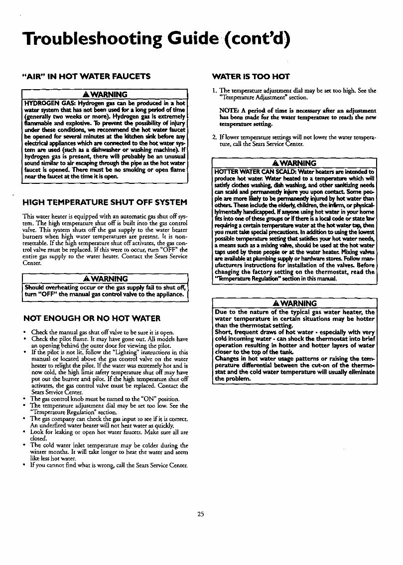
Troubleshooting Guide (cont'd)
"AIR" IN HOT WATER FAUCETS
AWARNINGHYDROGEN GAS: Hydmgangascan be producedin a hotwater _ thet hasnet beon usedfer a kingperindof _ne(generallytwo weeks or more). Hydrogengasis ext_melyflammable andexplosive.To preventthe possibilityof injuryundertheseco_ we recommendthe hot water faucetbe openedfor severalminutesat the kitchensinkbeforeanyelectricalapplianceswhichare connectedto the hot water sys-tem are used(suchas a dishwasheror washingmachine).Ifhydrogengas is present, there will probably be an unusualsoundsimilarto air escapingthroughthe pipeasthe hotwaterfaucet is opened.There must be no smokingor openflamenear the faucetat tbe time it isope_
HIGH TEMPERATURE SHUT OFF SYSTEM
This water heater is equipped with an automatic gas shut off sys-tem. The high temperature shut off is built into the gas controlvalve. This system shuts off the gas supply to the water heaterburners when high water temperatures are present. It is non-resetrable. If the high temperature shut offactivates, the gas,con-trol valve must be replaced. If this were to occur, turn OFF theentire gas supply to the water heater. Contact the Sears ServiceCenter.
_,WARNING
Should overheatingoccur or the gassupplyfail to shutoff,turn "OFF" the manual gascontrol valveto the appliance.
NOT ENOUGH OR NO HOT WATER
_ Check the manual gas shut off valve to be sure it is open.Check the pilot flame. It may have gone out. All models havean opening behind the outer door for viewing the pilot.If the pilot is not lit, _l!ow the _Lighting" instructions in thismanual or located above the gas control valve on the waterheater to relight the pilot. If the water was extremely hot and isnow cold, the high limit safety temperature shut off may haveput out the burner and pilot. If the high temperature shut offactivates, the gas controlvalve must be rephced. Contact theSears Service Center.The gas control knob must be turned to the "ON"position.T_e temperature adjustment dial may be set too low. See theTemperature Regulation section.
i he gas company can check the gas input to see if it iscorrect.An underfired water heater will nor heat water as quickly.Look for leaking or open hot water faucets. Make sure all areclosed.
• The cold water inlet temperature may be colder during thewinter months. It will take longer to heat the water and seemlike less hot water.
• If you cannot find what is wrong, call the Sears Service Center.
WATER IS TOO HOT
1. _e temperatureadjustment dial may be set too high. See theTemperature Adjustment" section.
NOTE: A period of time is oece_k_y after an adjustmenthas been made for the waser temperasure to t-eachthe newtemper, ware semng.
2. ]flower temperaturesetringswill nor lowerthe water tempera-ture, call the SearsServiceCenter.
AWARNINGHOTTERWATERCAN SCALI_.Water heatersam intendedtoproducehot water.Water heatedto a temperaturewhichwillsadslyclotheswashing,dishwashing,andother sanit_ngneedscanstaidand_ injureyouupencontact.Somepeo-pleam mere I.ila_.y..to be _ injuredby hotwater thanothe_ Theseincludetheelderl_children,sheinfirm,or physical-lyylrnentallyhandicapped.If anyoneusinghotwater inyourhomefitsintooneofthesegreupser iftham isalocalcndeer statelawrequiringacertaintemperaturewaterat thehotwater_ thenyoumust takespecial.pre_L Inaddi6onto uslngthe lowestpossibletemperature,settingthat satisfiesyourhotwater needs,a meanssuchasamixingvalve,shouldbe usedat the hotwatertapsusedbythesepeopleor at the water heater.Mixingvalvasare availableat plumbingsupplyor hardwarestores,Followman-ufacturersinstructionsfor installationof the valves.Beforechangingthe factory setting on the thermostat, read the'_remperatureRegulation"sectioninthismanual.
&WARNINGDue to the nature of the typical gas water heater, thewater temperature in certain situations may be hotterthan the thermostat setting.Short, frequent drawsof hot water - especiallywith verycold incomingwater - can shockthe thermostat into briefoperation resulting in hotter and hotter layersof watercloserto the top of the tank.Changesin hot water usagepatterns or raisingthe tom-perature differential between the cut-on of the thermo-scatand the cold water temperature will usuallyeliminatethe problem.
25

Troubleshooting Guide (cont'd)Leakage CheckpointsUse this guide to check a _Leaking_ water heater. Many suspect-ed _Leakers" are not leaking tanks. Often the source of the watercan be found and corrected.
If you arenot thoroughly familiar with your local gas codes yourwater heater, and safety practices, contact theCenter to check the water heater.
• ACAUTION IRead this manual Erst. Then before checking the waterheater make sure the gas supply has been turned]"OFF", end never turn the gas"ON" before the tank iscomp etely full of water,
® ®
A CAUTION [Never use thk water heater unlessit is completely filled ]with water. To prevent damage to the tank, the tankmust be filled with water. Water must flow from the hot Iwater faucet before turning "ON" gas to the water Iheater.
Water at the draft hood is water which has con-vapordensed out of the combustionprodncts. This is caused by aproblem in the vent. Contact the Sears Service Center.
O *Condensation may be seen on pipes in humid weather orpipe connections may be leaking.
O'The primary anode rod fitting be leaking.may
O Small amounts of water from temperature-pressure reliefvalve may be due to thermal expansion or high water pres-sure in your area,
o'The temperature-pressure relief valve may be leaking atthe tank fitting.
O Warer from a drain valve may be due to the valve openedslightly.
O'The drainvalvemay be leaking at the tank fitting.
O Combustion products contain water vapor which can con-dense on the cooler suff_ees of the tank. Droplets form anddrip into the fire or run on the floor. This is common atthe time of startup after installation and when incomingwater is cold.
Water in the water heater bottom or on the floor may befrom condensation, loose connections, or the relief valve.DO NOT replace the water heater until a full inspectionof all possible water sources is made and necessary correc-tive steps taken. Leakage from other appliances, waterlines, or ground seepage should also be checked.
NOTE: To check where threaded portion enters tank,insert cotton swab between jacket opening and fitting.If cotton is wet, follow "Draining" instructions in the"Service and Adjustment" section and then remove fit-ting. Put pipe dope or teflon tape on the threads andreplace. Then follow "Filling the Water Heater"instructions in the "Installation Insttuctlon_' section.
26

Notes
27
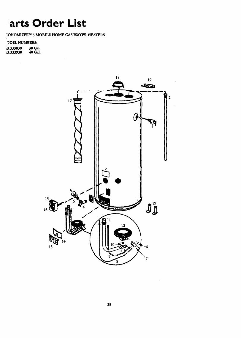
'arts Order List2ONOMIZER TM 5 MOBILE HOME GAS WATER HEATERS
3DEL NUMBERS:
•3.333830 30 Gal.,3.333930 40 Gal.
ZT_
1819
_2
13
28

Parts Order List (cont'd)ECONOMIZER TM 5 MOBILE HOME GAS WATER HEATERS
MODEL NUMBERS:
153.333830 30 Gal.153.333930 40 Gal.
KEY _
NO.
1
PART DESCRIFI_ON
Temperstule-PrrssureRalief Valve*
2 Primary Anode Rod
3 Modd Rating Platet4 Drain Valve
5 Drain Valve Washer (_7A2"x 'gu"x ¼"thick)**
6 Tharmocouple Clip
7 Pilot (Natural)7 Pilot [Propane (L.E)]
8 Thermocouple*
9 Pilot Tubing w/FittinBs
10 Burner Orifice (Natural)
10 Burner Orifice [Propane (L.E)]11 Manifold
12 Burner
13 Outer Door14 Inner Door
15 Gas Control Valve
16 TemperatureAdjustment Knob17 Flue Baffle
18 Draft Hood
19 Mounting Brackets# Manual
# Mag-Erad
Modal Numbers
153,333830 153.333930
PART NUMBERS
9000071 9000071
42-33085 4=_-33085
9000279 9000279
0270118 0270118
9000058 9000058
9001584 9001584
F145-0085 F145-0085
9000284 9000284
9000800 9000800
42-9231 42-9231
9000278 9000278
0230211 0230211
0230140 0230140
9002613 9002615
9000390 9000390
9000351 9000351
9000281 9000281
F145-0846 F145-0846
F145-0697 F145-0697
9000391 9000537
9000272 9000272
9001261 9001261
0291214
23600
# Not Illustrated* These parts are also availableat most Sears retail stores.**Also available at most hardware stores.t Replaced only upon return of damaged plate.
Now that you have purchased your Gas Water Heater, should aneed ever exist for repair parts or service, simply contact anySEARSService Center or call 1-800-4-REPAIR (1-800-473-7247).Be sure to provide pertinent factswhen you call or visit,
All parts listed may be ordered from any SEARS Service Center,most SEARS stores and by calling 1-800-366-PART (1-800-366-7247). If the pasts you need axenot stocked locally, your orderwillbe electronically transmitted to a SEARS Repair Parts DistributionCenter for handling.
THIS IS A REPMR PARTSLIST, NOT A PACKING LIST.
The model number of your Gas Water Heater will be found onthe model rating plate located near the gas control valve.
When ordering repair parts, always give the following infor-marion:
Model NumberPart Number
Part DescriptionName of Item
29

_lotes
30

Notes
31

WarrantyAbout Your WarrantyTHE PRICE OF YOUR WATERHEATER DOES NOT INCLUDEA FREE CHECKUP SERVICECALL. On Water Heater InstalatlomArrangedBy Sears,Searswarrantsthe installation.ON INSTALLATIONSNOT MADE BY SEARSAUTHORIZEDCONTRACTORS:1. YourSearswarrantyappliesto the product only,2, Searsdoes not warrant the installation.3. A charge will be madeon service calls due to poor or incomplete
imtalladon. These indude:
a.Adjusting thermostat.b. Lightingpilot.c. Leaksin pipesor fittings.d. Improper ventinge. Condensation
This manual is in non-technicalhngusge. It may help you ,avoidthecost of a needless servicecall. Many service calls reallyarent needed.Suchas when:1.The gasis turned "OFF".2. The pilot isout.3. A gasorwater leak isdue to loosepipe orconnections.
FULL ONE YEAR WARRANTY ON WATER HEATER
For one year from the date of purchase, when your Sears Kealmom water heater is installed and operated in accordance withthe instructions in this manual Sears will:
1. Repair defects in material or workmanship in this water heater, free of charge.
2. Furnish and install a new current model water heater of equal capacity and quality, free of charge, ifa leak occurs in thetank.
LIMITED WARRANTY ON TANKS THAT LEAK
After one year and through 5 years from the date of purchase, if a leak occurs in the tank, Sears will furnish a new currentmodel water heater of equal capacity and quality. You will be charged for installation.
If the water heater is subjected to commercial, institutional, industrial or other non-residential use, the above warranty cover-age for tanks that leak is effective for 2 years from the date of purchase.
iTo obtain warranty service, SIMPLY CONTACT THE NEAREST SEARS STORE OR SEARS SERVICE CENTER INTHE UNITED STATES This warranty applies only while this product ]s in use in the United States.
This warranty gives you specific legal rights and you may also have other rights which vary from state to state.
"SEARS, ROEBUCK AND CO., Dept. 817 WA, Hoffman Estates, IL 60179"
Sears Installation WarrantyIn addition to any warranty.¢xrendedto you on the Sears merchandiseinvolved,which warranty becomeseffectivethe date the merchandiseisinstalled should the workmanship of any Sears arran_d installationprove faulty within one year, Searswill, upon notice from you, causesuch faults to be correctedat no additionalcost to you. If you want thisheater professionallyinstalled by Searscontact your SearsSalesperson.They will arrangefor prompt, quality installation.
Parts Ordering InformationThe model number of your gaswaterheater is found on the model rat-ing plate on the front of the waterheater.
Sears Installation PolicyAll installation labor arrangedby Searsshallbeperformed in a neat,workmanlikemanner in accordancewithgenerallyacceptedtrade prac-tices. Further, all iustallatiom shallcomplywith all local faws,codesregulationsand ordinances.The customershallalsobe protected, dur-ing installation,by insurance relatingto property damage,Worker'sCompensation and PublicLiability.Ifyou want this waterheater professionallyinstalledby SearscontactyourSalesperson.They willarrangefor prompt, quality installationbySearsauthorizedcontractors.
FortherepairorreplacementpartsyouneeddelivereddirectlytoyourhomeCall7am-7 pro,7daysaweek1-800-366-PART
(1-eoc_6e-727e)
Forin-homemajorbrandrepairserviceCall24hoursaday,7 daysaweek1-800-4-REPAIR
(1-800-473-7247)
Sears, Roebuck and Co., Hoffman Estates, IL 60 179 U.S.A. 029_z_4-_.