econo gradient pump instruction manual · the econo gradient pump (egp) is a two-channel,...
TRANSCRIPT
EC
ON
O
GR
AD
IEN
T
PU
MP
Econo Gradient PumpInstruction Manual
4006161B.qxd 8/14/2003 8:09 AM Page 1

SAFETY
Caution/WarningDisconnect power to the Econo Gradient Pump beforeservicing. No user-serviceable parts are inside the unit.Refer servicing to Bio-Rad service personnel.
The Bio-Rad Econo Gradient Pump is certified to meet the I.E.C.1010-1* standard for safety of laboratory equipment. Certifiedproducts are safe to use when operated in accordance with theinstruction manual. This safety certification does not extend to otherchromatography equipment or accessories not I.E.C. 1010 certified,even when connected to this Bio-Rad Econo Gradient Pump.
This instrument is intended for laboratory use only.
The Bio-Rad Econo Gradient Pump conforms to the “Class A“standards for Electromagnetic Emissions, intended for laboratoryequipment applications. It is possible that emissions from this productmay interfere with some sensitive appliances when placed nearby oron the same circuit as those appliances. The user should be awareof this potential and take appropriate measures to avoid interference.
This instrument should not be modified or altered in any way.Alteration of this instrument will void the manufacturer’s warranty,void the I.E.C. 1010 certification, and create a potential safety hazardfor the user.
Bio-Rad is not responsible for any injury or damage caused by theuse of this instrument for purposes other than for which it is intendedor by modifications of the instrument not performed by Bio-Rad or anauthorized agent.
*I.E.C. 1010 is an internationally accepted electrical safety standard forlaboratory instruments.
Safety
i
!
4006161B.qxd 8/14/2003 8:09 AM Page i
TABLE OF CONTENTS
Safety . . . . . . . . . . . . . . . . . . . . . . . . . . . . . . iSection 1 Introduction . . . . . . . . . . . . . . . . . . . . 1Section 2 Unpacking and Setting Up . . . . . . . . . 2
2.1 Unpacking Instructions . . . . . . . . . . . . . 22.2 Voltage Conversion . . . . . . . . . . . . . . . 3
Section 3 Physical Description and Control Features 43.1 Front Panel Functions . . . . . . . . . . . . . 43.2 Rear Panel Functions . . . . . . . . . . . . . . 8
Section 4 Tubing Selection and Installation . . . . 104.1 Tubing Selection . . . . . . . . . . . . . . . . . . 104.2 Tubing Installation . . . . . . . . . . . . . . . . 124.3 Platen Adjustment . . . . . . . . . . . . . . . . 13
Section 5 System Operation . . . . . . . . . . . . . . . . 145.1 Remote Mode . . . . . . . . . . . . . . . . . . . . 145.2 Setup Mode . . . . . . . . . . . . . . . . . . . . . 145.3 Manual Mode . . . . . . . . . . . . . . . . . . . . 20
5.3.1 Setting Flow Rate or Motor Speed 205.3.2 Setting Buffer Gradient . . . . . . . 205.3.3 Setting Auxiliary Valve Control . 21
5.4 Program Mode . . . . . . . . . . . . . . . . . . . 215.5 Running a Program . . . . . . . . . . . . . . . 23
5.5.1 Holding a Run . . . . . . . . . . . . . 245.5.2 Pausing a Run . . . . . . . . . . . . . 245.5.3 Aborting a Run . . . . . . . . . . . . . 245.5.4 Power Failure While in Run Mode 25
Section 6 Operation with other Bio-Rad Instruments 24Section 7 Cleaning and Maintenance . . . . . . . . . 27
7.1 Fuse Replacement and Voltage Conversion 33Section 8 Troubleshooting . . . . . . . . . . . . . . . . . 35Section 9 Embedded Functions . . . . . . . . . . . . . 38
9.1 Firmware Confirmation . . . . . . . . . . . . . 389.2 Reset . . . . . . . . . . . . . . . . . . . . . . . . . . 38
Appendix A Technical Specifications . . . . . . . . . . 39Appendix B Connection to Other Instruments . . . 41
Table of Contents
iii
4006161B.qxd 8/14/2003 8:09 AM Page iii
Appendix C Warranty . . . . . . . . . . . . . . . . . . . . . . . 43Appendix D Ordering Information . . . . . . . . . . . . . 44
Table of Contents
iv
4006161B.qxd 8/14/2003 8:09 AM Page iv

1.0 INTRODUCTION
The Econo Gradient Pump (EGP) is a two-channel, bi-directional,variable speed peristaltic pump for low-pressure chromatography andgeneral laboratory use. It offers a full range of features to facilitateease of use as a stand-alone pump or as a part of the BioLogicDuo-Flow System running software version 3.0 or later..
As a stand-alone pump, the EGP delivers flow rates from 2 µl/min to40 ml/min using a single channel of 0.51 mm or dual channels of 3.2mm ID tubing respectively. The EGP has the ability to self-calibratethe flow rate for 0.51, 0.8, 1.6, and 3.2 mm ID tubing, displaying pumpoutput in ml/min. The pump can be programmed to start or stop Bio-Rad fraction collectors and chart recorders.
A membrane key panel with graphic icon displays allows easy userinterface. The EGP will store one program in its non-volatile memory.
Figure 1-1. Econo Gradient Pump.
Introduction
1
ECONO GRADIENT PUMP
Remote
Setup
Manual
Program
ModeStep
Cancel
Next
RunPurgeReverse
4006161B.qxd 8/14/2003 8:09 AM Page 1
2.0 UNPACKING AND SETTING UP
2.1 UNPACKING INSTRUCTIONS
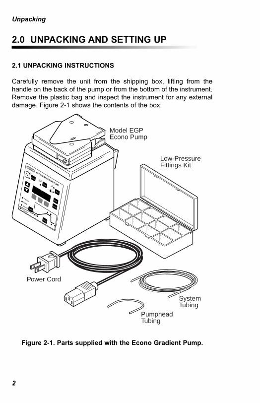
Carefully remove the unit from the shipping box, lifting from thehandle on the back of the pump or from the bottom of the instrument.Remove the plastic bag and inspect the instrument for any externaldamage. Figure 2-1 shows the contents of the box.
Figure 2-1. Parts supplied with the Econo Gradient Pump.
Unpacking
2
Model EGPEcono Pump
Low-PressureFittings Kit
Power Cord
SystemTubing
PumpheadTubing
4006161B.qxd 8/14/2003 8:09 AM Page 2

Your Econo Gradient Pump was carefully tested at the factory andwas shipped in good working order. If any part is missing ordamaged, contact your local Bio-Rad office immediately.
2.2 VOLTAGE CONVERSION
Warning: The Econo Gradient Pump is shipped in its 100/120 Vconfiguration. To operate at 220/240 V, refer to the procedure insection 7, Cleaning and Maintenance, to make the conversion.Failure to follow this procedure may result in damage to the unit andinvalidation of the warranty.
Unpacking
3
4006161B.qxd 8/14/2003 8:09 AM Page 3

3.0 PHYSICAL DESCRIPTION AND CONTROLFEATURES
3.1 FRONT PANEL FUNCTIONS
Figure 3-1. Front Panel Controls and Displays.
Description
4
ECONO GRADIENT PUMP
Remote
Setup
Manual
Program
ModeStep
Cancel
Next
RunPurgeReverse
LCD Display
Soft KeysArrow Keys
Platen
4006161B.qxd 8/14/2003 8:09 AM Page 4

Front Panel Function
[LCD; see figure 3-1] LCD DisplayThis display has two rows of 16 characters.Different windows will appear on this displaydepending on the requests made by theuser. Some windows will display operatingparameters, while others will allow entry ofvariables such as flow rates, valve positionand programming steps. Choices are shownin the lower row, above one of the three softkeys. A selection is indicated in uppercaseletters.
Soft KeysThese keys are used to select choicesdisplayed on the LCD. A selection isindicated in uppercase letters. Pressing andholding a soft key and an arrow key acts toaccelerate the action of the arrow keys.
Arrow KeysThese keys are used for setting systemparameters when programming the system,and for selecting which parameter to displaywhen running the pump. A value input withthe arrow key can be erased or acceptedwith the Cancel and Next keys respectively.Pressing and holding an arrow key willaccelerate the action of the arrow keys.
Next KeyPressing Next will accept any valuesdisplayed in the current window andadvance to the next window.
Description
5
Next
4006161B.qxd 8/14/2003 8:09 AM Page 5

Front Panel Function
Cancel KeyPressing Cancel will clear an entry that hasbeen input with either the arrow or soft keys.If no entry has been made, the previouswindow will be displayed. This allowspassage through the windows in the reversedirection.
Run/Stop KeyThis key is used to start or stop the pump inboth Manual mode and Program modeoperation. The pump will run in the clockwisedirection by factory default. The green andred LEDs are illuminated when the EconoGradient Pump is running or stopped,respectively. The direction can be changedusing the Reverse Direction key, when thepump is stopped.
Reverse Direction KeyThis key changes the direction of pumphead rotation. The Econo Gradient Pumpmust be stopped before the direction can bechanged. This key is not operable when thepump is running. The yellow and orangeLEDs are illuminated when the pump isrunning clockwise (CC) and counter-clockwise (CCW), respectively.
Description
6
Cancel
Run
Reverse
4006161B.qxd 8/14/2003 8:09 AM Page 6
Front Panel Function
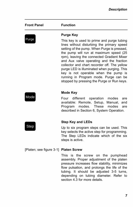
Purge KeyThis key is used to prime and purge tubinglines without disturbing the primary speedsetting of the pump. When Purge is pressed,the pump will run at maximum speed (25rpm), leaving the connected Gradient Mixerand Aux valve operating and the fractioncollector and chart recorder off. The yellowpurge LED is illuminated when purging. Thiskey is not operable when the pump isrunning in Program mode. Purge can bestopped by pressing the Purge or Run keys.
Mode KeyFour different operation modes areavailable: Remote, Setup, Manual, andProgram modes. These modes aredescribed in Section 6, System Operation.
Step Key and LEDsUp to six program steps can be used. Thiskey selects the active step for programming.The Step LEDs indicate which of the sixsteps is active.
[Platen; see figure 3-1] Platen ScrewThis is the screw on the pumpheadassembly. Proper adjustment of the platenpressure increases flow stability, minimizesflow pulsation, and prolongs the life of thetubing. It should be adjusted 3-5 turns,depending on tubing diameter. Refer tosection 4.3 for more details.
Description
7
Purge
Mode
Step
4006161B.qxd 8/14/2003 8:09 AM Page 7
3.2 REAR PANEL FUNCTIONS
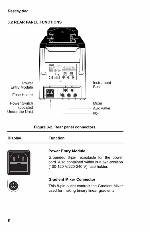
Figure 3-2. Rear panel connectors.
Display Function
Power Entry ModuleGrounded 3-pin receptacle for the powercord. Also contained within is a two-position(100-120 V/220-240 V) fuse holder.
Gradient Mixer ConnectorThis 8-pin outlet controls the Gradient Mixerused for making binary linear gradients.
Description
8
PowerEntry Module
Fuse Holder
Instrument Bus
MixerAux ValveI/O
Power Switch(Located
Under the Unit)
MIXER
INSTR BUS
AUX VALVEI/O
INSTR BUS
CAUTIONWARNING
Warning: Disconnect supply before servicing.
Model No. Econo Gradient PumpSerial No. 491 BRAC VoltageMax Current FrequencyFuse Type
0.4 A50-60 Hz0.4 A
0.2 A50-60 Hz0.2 A
Advertissement:: Couper l'alimentation avantl'entretien et depannage.
Made in U.S.A.
EN61010-1
4006161B.qxd 8/14/2003 8:09 AM Page 8

Display Function
Aux Valve ConnectorThis 8-pin connector controls auxiliaryvalves such as the optional SV-3 Divertervalve or the optional Splitter valve.
I/O ConnectorThis 8-pin outlet provides start signals to theModel 1327 Chart Recorder, the Model 2110Fraction Collector, or the Model 2128Fraction Collector. Simultaneous control ofboth the Model 2110 and the Model 1327, orthe Model 2128 and the Model 1327, can beaccomplished via the 2110-Y cable and the2128-Y cable respectively. I/O connectorpinouts are given in Appendix B. A TTL inputis also present which allows the pump to bestarted remotely.
[base; see figure 3-2] The underside of the Econo Gradient Pumpcontains the power switch.
Description
9
4006161B.qxd 8/14/2003 8:09 AM Page 9

4.0 TUBING SELECTION AND INSTALLATION
4.1 TUBING SELECTION
The Econo Gradient Pump may be used with most flexible tubinghaving an inner diameter less than or equal to 3.2 mm (1/8”), and awall thickness of 1.0 mm or less, including Silicone, Tygon, andPharMed. Silicone tubing, the most inert of the three, is suitable foraqueous and polar solutions. Tygon is suitable for most aqueoussolutions. It will generally have the shortest lifetime of the three andshould not be used for the pumphead. PharMed is the longest lastingof the three, and will provide the most consistent flow rate over time.Figure 4-1 shows approximate flow rate ranges with different tubingsizes. Flow rates above 20 ml/min may be obtained by plumbing twochannels of 3.2 mm tubing through the pump and joining them at theoutput.
Very low flow rates can be achieved with tubing having ID as small as0.51 mm. Tubing this small must be jacketed inside larger tubing andrequires an adapter. These items are included in the optional splittervalve kit.
Figure 4-1. Approximate Flow Rate Ranges.
Tubing length and the amount of tubing prestretch have a significanteffect on both flow rate calibration and reproducibility of flow. ThePharMed tubing supplied with the Econo Gradient Pump has beencut to a predetermined length to accommodate tubing prestretch.(Silicon tubing in precut lengths is also available from Bio-Rad. Seeordering information in Appendix D.)
Tubing Selection
10
TUBING SIZE(ID x WALL) FLOW RATE RANGE (ml/min)
0.51 x 0.8 mm
0.8 x 0.8 mm
1.6 x 0.6 mm
3.2 x 0.8 mm
.001 .002 .005 .01 .02 .05 .10 20.20 .5 1.0 2 5 10 ml/m
4006161B.qxd 8/14/2003 8:09 AM Page 10

When using tubing other than precut tubing from Bio-Rad, the tubingmust be cut to the following lengths to accommodate prestretch:
Tubing LengthTygon, PharMed 179 mm +/- 1.5 (7.04” +/- 0.05)Silicone 171 mm +/- 1.5 (6.75” +/- 0.05)
Install tubing onto the pump head as described in Section 4.2.Warning: If using tubing other than the type supplied by Bio-Rad, make sure the wall thickness is not greater than 1.0mm. Using tubing with a greater wall thickness can damagethe pump and void your warranty.
Figure 4-2. Tubing installation.
Tubing Selection
11
4006161B.qxd 8/14/2003 8:09 AM Page 11
4.2 TUBING INSTALLATION
1. Referring to Figure 4-2, pull the platen cam lever away from thepump head to unlock the platen and slide the platen away fromthe pump head frame assembly, exposing the rollers.
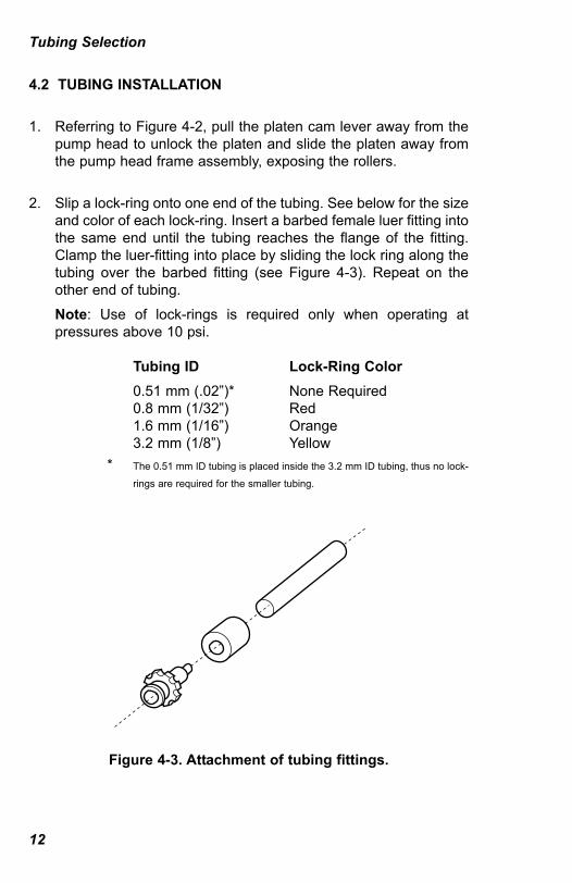
2. Slip a lock-ring onto one end of the tubing. See below for the sizeand color of each lock-ring. Insert a barbed female luer fitting intothe same end until the tubing reaches the flange of the fitting.Clamp the luer-fitting into place by sliding the lock ring along thetubing over the barbed fitting (see Figure 4-3). Repeat on theother end of tubing.Note: Use of lock-rings is required only when operating atpressures above 10 psi.
Tubing ID Lock-Ring Color0.51 mm (.02”)* None Required0.8 mm (1/32”) Red1.6 mm (1/16”) Orange3.2 mm (1/8”) Yellow
* The 0.51 mm ID tubing is placed inside the 3.2 mm ID tubing, thus no lock-
rings are required for the smaller tubing.
Figure 4-3. Attachment of tubing fittings.
Tubing Selection
12
4006161B.qxd 8/14/2003 8:09 AM Page 12

3. Insert one end of the tubing into the tubing retaining bracket ofthe pump head. Lightly pull the tubing around the rollers toremove slack. Attach the other end of tubing into the tubingretaining bracket on the opposite side of the pump head.
4. Slide the platen back into the pump head frame assembly until itrests up against the tubing. Press the cam lever in toward thepump head, locking the platen up against the tubing and rollers.The platen may be inserted with the cam lever on the left or theright.
4.3 PLATEN ADJUSTMENT
Proper adjustment of the platen pressure increases flow stability,minimizes flow pulsation, and prolongs the life of the tubing.
Once the tubing is installed, completely loosen the platen adjustmentscrew counterclockwise until the stop is reached. Use the informationin the table below to determine the appropriate number of turns thatare required.
Overtightening the platen adjustment screw will reduce flow rate andshorten tubing life. If the platen is too loose, flow rate will decrease asbackpressure increases. The platen must be adjusted each timepumphead tubing is replaced.
Tubing ID Number of Turns from Fully Open
0.8 mm (1/32”) 51.6 mm (1/16”) 43.2 mm (1/8”) 3
Tubing Selection
13
4006161B.qxd 8/14/2003 8:09 AM Page 13
5.0 SYSTEM OPERATION
There are four modes of system operation:• Remote• Setup• Manual• Program, including running the system
5.1 REMOTE MODE
The Econo Gradient Pump can be connected to the BioLogicDuo-Flow Workstation running software version 3.0 or later with anInstrument bus cable (System cables 17, 18, 19, or 21). When theBioLogic assumes control of the Econo Gradient Pump, the EconoGradient Pump is automatically set to Remote Mode. In RemoteMode, the Econo Gradient Pump keys provide limited control,allowing only basic observation of Econo Gradient Pump operatingparameters.
5.2 SETUP MODE
Each of the pump’s features can be customized in Setup mode.While the pump is stopped, plug in the desired valves (i.e., GradientMixer, SV-3 Diverter valve, or Splitter valve) into the connectors onback. (Note, these valves must be plugged in before any run requiringthem is started.) Then press the Mode key until the Setup LED isilluminated. Each of the Setup windows is discussed on the followingpages.
Note: When a selection is made, it will be displayed in capitalletters.
System Operation
14
4006161B.qxd 8/14/2003 8:09 AM Page 14

Screen 1. Flow Rate Selection.Use the soft keys to select either RPM (revolutions per minute) orml/m. This information will be used in writing a protocol from theProgram mode and in using the Manual mode.• If RPM is selected, the user may control the pump speed in
revolutions per minute (RPM). Pressing Next skips to screen 9.• If ML/M is selected, the user is required to calibrate the pump.
This choice enables the user to control the pump speed in ml/m.Pressing Next continues to screen 2.
1 Flow rateRPM ml/m
Screen 2. Pump Calibration.The tubing ID is selected here. Calibration can be accomplished byeither entering the tubing ID or actually measuring the flow rate.• If you select “Tube ID” pressing Next continues to screen 3.• If you select “flow” pressing Next skips to screen 4.
2 Calibrate byTUBE ID flow
Note: Flow rate depends on condition of tubing, platen adjustment,and back pressure. For maximum flow rate accuracy, calibrate theflow rate as the tubing ages or becomes worn, when the tubing isreplaced, if the platen is readjusted, or if back pressure changessignificantly.
Screen 3. Pump Calibration by Tubing ID.The tubing ID can be entered here. Use the arrow keys or the centersoftkey to scroll through the available tubing ID choices. The pumpcalibration is estimated from this. Enter the tubing ID and press Nextto accept the value and advance to screen 6.
3 Enter tube ID___ mm
System Operation
15
4006161B.qxd 8/14/2003 8:09 AM Page 15

System Operation
16
Screen 4. Pump Calibration by Measured Flow.Pressing the left or right soft keys will start the pump for the selectedtime. Collect the pump effluent in a graduated cylinder. Duringcalibration, the pump runs at half speed (12.5 RPM). Typical volumescollected after a 2-minute run are 20 ml, 6.4 ml, 1.7 ml, and 700 µl fortubing IDs of 3.2 mm, 1.6 mm, 0.8 mm, and 0.51 mm respectively.The volume collected is entered in screen 5.
4 Start cal run 2m 20m
The time remaining in the calibration run will be displayed as shownbelow. It is not necessary to run a calibration to completion.
Time = _min: _sEnd ABORT
• End: Ends volume collection and continues to screen 5,permitting flow rate calibration, before the timer reaches 0minutes.
• Abort: Ends volume collection and returns to screen 1,disallowing flow rate calibration.
Screen 5. Calibrated Volume.When the calibration run ends, enter the volume of liquid that wascollected.
5 Volume ? _ ml
Press Next to accept the entered value and advance to screen 6.Press Cancel to return to screen 4 and repeat the calibration.
4006161B.qxd 8/14/2003 8:09 AM Page 16

Screen 6. Selecting Units for Programming.Programming steps can be described in either units of time (inminutes) or volume (in ml).
6 Program Steps TIME vol
Pressing the left soft key selects time; the right key selects volume.Pressing Next advances to screen 8 if a Splitter valve is present orscreen 9 if a Splitter valve is not present.
Screen 7 (not displayed). This is available for future upgrades.
Screen 8. Splitter Valve Period Selection.The Econo Gradient Pump automatically detects the presence of asplitter valve. The default period is 2 seconds. This parameter, inconjunction with the “%-split” parameter, may be varied for streamsplitting, process sampling, or on-line biological activity assays. Moreinformation is included in the splitter valve instruction manual. If youare uncertain about this value, accept the default of 2 seconds andadjust it later according to your application needs.
8 Split period __ sec
Enter a new value for the split period and press Next to advance toscreen 9.
System Operation
17
4006161B.qxd 8/14/2003 8:09 AM Page 17

Screen 9. Biologic System Address Number.The Econo Gradient Pump can be connected to the BioLogic HR orBioLogic Duo-Flow workstation via an Instrument bus cable (Systemcables 17, 18, 19, or 21). When connected, the address of the EconoGradient Pump must correspond to the address recognized by theBioLogic System. This address is only relevant when the EconoGradient Pump is connected to the BioLogic System. The defaultaddress is 1.
9 Address # 001
Use the arrow keys to enter a new address, and press Next to acceptand advance to screen 10.
Screen 10. Revolutions Counter.The performance of the peristaltic tubing degrades with use. Thisrevolution counter provides a measure of wear experienced by thetubing. The relation between revolutions and tube life must beempirically determined because it is dependent on several factorsincluding load, tubing type and platen pressure.
10 Revolutions=Reset ___
Pressing the Reset softkey resets the counter back to 0. PressingNext will accept the displayed value and advance to screen 11.
Screen 11. LCD Contrast.The LCD display contrast is set here.
11 LCD Contrast__%
Use the arrow keys to enter the desired contrast and press Next toadvance to screen 12.
System Operation
18
4006161B.qxd 8/14/2003 8:09 AM Page 18
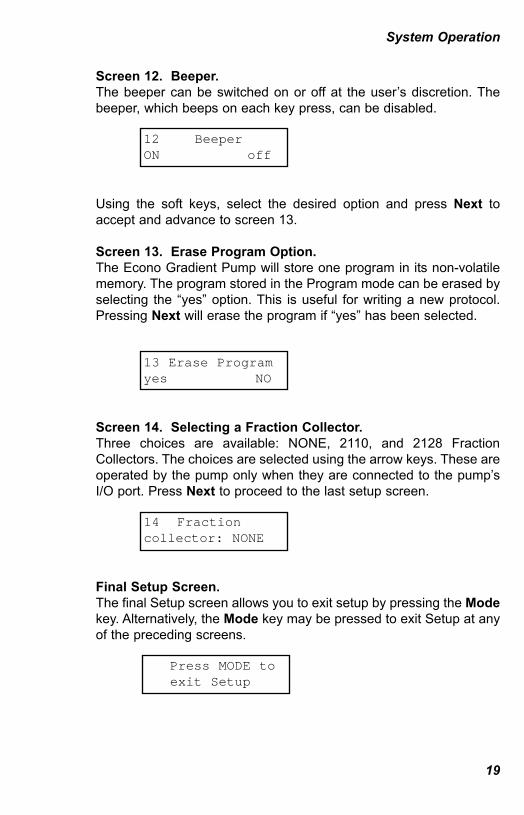
Screen 12. Beeper.The beeper can be switched on or off at the user’s discretion. Thebeeper, which beeps on each key press, can be disabled.
12 Beeper ON off
Using the soft keys, select the desired option and press Next toaccept and advance to screen 13.
Screen 13. Erase Program Option.The Econo Gradient Pump will store one program in its non-volatilememory. The program stored in the Program mode can be erased byselecting the “yes” option. This is useful for writing a new protocol.Pressing Next will erase the program if “yes” has been selected.
13 Erase Programyes NO
Screen 14. Selecting a Fraction Collector.Three choices are available: NONE, 2110, and 2128 FractionCollectors. The choices are selected using the arrow keys. These areoperated by the pump only when they are connected to the pump’sI/O port. Press Next to proceed to the last setup screen.
14 Fraction collector: NONE
Final Setup Screen.The final Setup screen allows you to exit setup by pressing the Modekey. Alternatively, the Mode key may be pressed to exit Setup at anyof the preceding screens.
Press MODE toexit Setup
System Operation
19
4006161B.qxd 8/14/2003 8:09 AM Page 19

5.3 MANUAL MODE
The Econo Gradient Pump and attached devices can be controlledusing the pump’s front panel membrane keys and LCD display whilein Manual mode. Press the Mode key until the Manual LED isilluminated. Up to three parameters (depending on how manyoptional devices are connected to the Econo Gradient Pump) can becontrolled. Choose a field on the LCD by pressing the correspondingsoft key. The selected parameter can be adjusted using the arrowkeys. Pressing the Up arrow key will raise the value of the parameter,pressing the Down arrow key will lower the value. Pressing andholding a soft key acts to accelerate the action of the arrow keys.
5.3.1 Setting Flow Rate or Motor Speed
Either RPM or ml/min will be displayed, depending on the setting inSetup, screen 1. Flow rate or motor speed is selected by pressing theleft soft key. The speed is adjusted by depressing the arrow keys. Ifneither a Gradient Mixer nor an auxiliary valve are connected, theLCD looks like this:
RPM Selected Flow Rate Selected
RPM ml/m 3.45 6.40
5.3.2 Setting Buffer Gradient
Buffer gradient (%B) is selected by pressing the center soft key. Thisoption is only available if the Gradient Mixer is connected to thepump’s Mixer connector. The percent of the gradient is adjusted usingthe arrow keys. Pressing and holding a softkey acts to accelerate theaction of the arrow keys.
ml/m %B 3.45 0
System Operation
20
4006161B.qxd 8/14/2003 8:09 AM Page 20

5.3.3 Setting Auxiliary (SV-3 or Splitter) Valve Control
Control for an auxiliary valve is selected by pressing the right soft key.This option is available if a valve is connected to the Auxiliary port onback of the Econo Gradient Pump. The valve type is automaticallyrecognized. The SV-3 diverter valve must be connected if you wish toprogram a collection window with either the model 2110 or 2128Fraction collector. With an auxiliary valve and Gradient Mixerattached, the LCD display would look like this:
with Mixer and Diverter valve with Mixer and Splitter valve
ml/m %B Divert ml/m %B Split3.45 100 WASTE 3.45 100 100%
5.4 PROGRAM MODE
The Econo Gradient Pump can be programmed to perform up to sixsequential steps automatically. Selections made in the Setup screenwill be reflected in the Program screen. The Program screen willdisplay the program step (either time or volume), the %B if a GradientMixer is present, and the flow rate/motor speed (RPM.) For the firstprogram step, the time (or volume) parameter is -0- and is noteditable. Here is an example of a Program screen where volume andflow rate have been selected in Setup and a Gradient Mixer isconnected.
ml %B ml/m -0- 15 5.0
System Operation
21
4006161B.qxd 8/14/2003 8:09 AM Page 21
Each field may be selected with the corresponding soft key. Thearrow keys are then used to increment or decrement the value.Pressing the Step key or the Next key will accept the displayedvalues and advance to the next step. The program end occurs wheneither 6 steps have been entered, or two identical steps (pressingStep twice) are entered sequentially.
If an auxiliary valve is present, a screen will appear afterprogramming is completed.
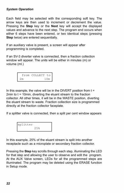
If an SV-3 diverter valve is connected, then a fraction collectionwindow will appear. The units will be either in minutes (m) orvolume (ml.)
from COLLECT to 2m 10m
In this example, the valve will be in the DIVERT position from t =2min to t = 10min, diverting the eluant stream to the fractioncollector. All other times, it will be in the WASTE position, divertingthe eluant stream to waste. Fraction collection size is programmeddirectly at the fraction collector faceplate.
If a splitter valve is connected, then a split per cent window appears
splitter 25%
In this example, 25% of the eluant stream is split into anotherreceptacle such as a microplate or secondary fraction collector.
Pressing the Step key scrolls through each step, illuminating the LEDfor that step and allowing the user to observe and edit the program.At the AUX Valve screen, LEDs for all the programmed steps areilluminated. The program may be deleted using the ERASE functionin Setup mode.
System Operation
22
4006161B.qxd 8/14/2003 8:09 AM Page 22

5.5 RUNNING A PROGRAM
To start a program (be sure to enter the Program mode by using theMode key), press the Run key. This will start the run. By using theright soft key, the Run screen can show time elapsed or timeremaining on the run. If program steps are in volume, elapsed orremaining volume will also be displayed.
Time elapsed Time remaining
__m: __s __mm: __s __ml elapsed __ml left
Pressing the Next key will show the current gradient conditions:
with Mixer and Diverter valve with Mixer and Splitter valve
ml/m %B Divert ml/m %B Split
If the program is allowed to finish normally, the Econo Gradient Pumpbeeps and displays the following screen:
Program Finished
Pressing any key will put the Econo Gradient Pump into Manualmode.
The run may be interrupted by pressing the Next key twice. Doing sobrings up the following screen:
Hold Pause Abort
System Operation
23
4006161B.qxd 8/14/2003 8:09 AM Page 23
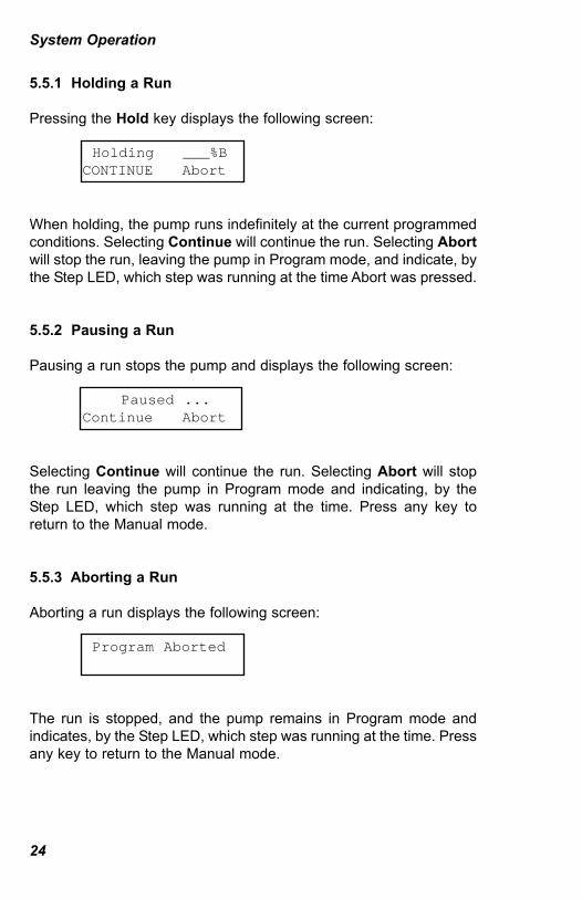
5.5.1 Holding a Run
Pressing the Hold key displays the following screen:
Holding ___%B CONTINUE Abort
When holding, the pump runs indefinitely at the current programmedconditions. Selecting Continue will continue the run. Selecting Abortwill stop the run, leaving the pump in Program mode, and indicate, bythe Step LED, which step was running at the time Abort was pressed.
5.5.2 Pausing a Run
Pausing a run stops the pump and displays the following screen:
Paused ... Continue Abort
Selecting Continue will continue the run. Selecting Abort will stopthe run leaving the pump in Program mode and indicating, by theStep LED, which step was running at the time. Press any key toreturn to the Manual mode.
5.5.3 Aborting a Run
Aborting a run displays the following screen:
Program Aborted
The run is stopped, and the pump remains in Program mode andindicates, by the Step LED, which step was running at the time. Pressany key to return to the Manual mode.
System Operation
24
4006161B.qxd 8/14/2003 8:09 AM Page 24
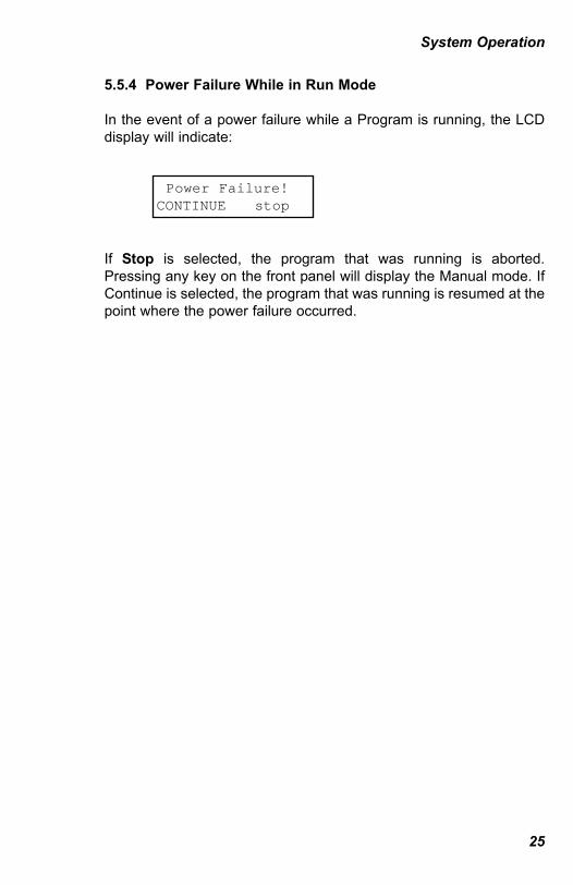
5.5.4 Power Failure While in Run Mode
In the event of a power failure while a Program is running, the LCDdisplay will indicate:
Power Failure! CONTINUE stop
If Stop is selected, the program that was running is aborted.Pressing any key on the front panel will display the Manual mode. IfContinue is selected, the program that was running is resumed at thepoint where the power failure occurred.
System Operation
25
4006161B.qxd 8/14/2003 8:09 AM Page 25
6.0 OPERATION WITH OTHER BIO-RADINSTRUMENTS
The Econo Gradient Pump (EGP) may be used with otherchromatography components (the Model 2110 or Model 2128 fractioncollectors and the Model 1327 Chart recorder), and with the BioLogicDuo-Flow System running software version 3.0 or later, the highresolution liquid chromatography systems. Each of these connectionsis discussed in the following table. Refer also to Figure 6-1 forsystem cabling and to Figure 6-2 for system plumbing.
Table 6-1. Connecting the Econo Gradient Pump to other Bio-Rad instruments
Model 2128 Fraction Collector
1. This cable connects the EGP (mini-DIN I/Osocket) to the 15-pin D-connector on the fractioncollector and transmits “start” and “stop” signals.
If the Model 1327 Chart Recorder is present,connect the cable’s remaining end to the chartrecorder. If the chart recorder is not present,then place this portion of the cable aside.
2. Power up the EGP and the fraction collector (andthe chart recorder, if present.)
3. Enter the fraction collector’s Standard mode andset all fraction collector parameters from itsfaceplate.
The EGP will automatically start the fractioncollector when a programmed run is started. Ifthe SV-3 diverter valve is connected to the EGP,then fraction collection will begin at the point inthe program when the diverter valve is in theDIVERT position.
Other Instruments
26
Cable #23
Catalog #731-9009
4006161B.qxd 8/14/2003 8:09 AM Page 26
Model 2128 Fraction Collector (continued)
Alternatively, one may use the Model 2128 DiverterValve; it will respond to the program in the Model2128 Fraction Collector itself, not from the EGP.
If HOLD is selected during the program, then thepump will continue pumping at the current conditionsand fraction collection will continue as programmed.
If PAUSE is selected during the program, then thepump and fraction collector will stop.
The pump and fraction collector will resume whenCONTINUE is selected.
Model 2110 Fraction Collector
1. This cable connects the EGP (mini-DIN I/Osocket) to the 9-pin D-connector on the Model2110 Fraction Collector and transmits “start” and“stop” signals.
If the Model 1327 Chart Recorder is present,connect the cable’s remaining end to the chartrecorder. If the chart recorder is not present,then place this portion of the cable aside.
2. Power up the EGP and the fraction collector (andthe chart recorder, if present.)
3. Select collection by time or by drops by pressingthe Time/Drop key on the fraction collector’sfaceplate.
When the EGP is running in Manual mode, the2110 fraction collector will not start automatically.It may be started from is own faceplate if fractioncollection is required.
Other Instruments
27
Cable #22
Catalog #731-9010
4006161B.qxd 8/14/2003 8:09 AM Page 27
Model 2110 Fraction Collector (continued)
When a programmed run is started, the EGP willautomatically start the fraction collector. If the SV-3diverter valve is connected to the EGP, then fractioncollection will begin at the point in the program whenthe diverter valve is in the FRAC position.
If HOLD is selected during the program, then thepump will continue pumping at the current conditionsand fraction collection will continue as programmed.
If PAUSE is selected during the program, then thepump and fraction collector will stop.
The pump and fraction collector will resume whenCONTINUE is selected.
Model 1327 Chart Recorder
As described above, these cables connect fractioncollectors and the Model 1327 Chart Recorder to theEGP. The fraction collector part of the cable shouldbe put aside if a fraction collector is not present. TheEGP will automatically start and stop the chartrecorder. The parameters should be set at the chartrecorder itself.
If a fraction collector is present, then the fractioncollector marks are superimposed on the UV tracedirectly.
If HOLD is selected during the program, then thepump will continue pumping at the current conditionsand the chart recorder will continue recording.
Other Instruments
28
EitherCable #22(Catalog #731-9010)orCable #23(Catalog #731-9009)
4006161B.qxd 8/14/2003 8:09 AM Page 28

Model 1327 Chart Recorder (continued)
If PAUSE is selected during the program, then thepump and chart recorder will stop.
The pump and chart recorder will resume whenCONTINUE is selected.
Model EM-1 UV Monitor
None A connection is not required between the pump andthe EM-1 UV Monitor. To record UV data onto theModel 1327 Chart Recorder, use cable #4, 8-pinmini-DIN to banana plug cable. It is supplied with theUV Monitor. The banana plugs plug into Channel 1 ofthe chart recorder. The UV trace will be displayed bythe blue pen.
Model EG-1 Gradient Monitor
None A connection is not required between the pump andthe EG-1 Gradient Monitor. To record the gradientdata onto the Model 1327 Chart Recorder, use cable#4, 8-pin mini-DIN to banana plug cable. It issupplied with the Gradient Monitor. The bananaplugs plug into Channel 2 of the chart recorder. Thegradient trace will be displayed by the red pen.
Other Instruments
29
4006161B.qxd 8/14/2003 8:09 AM Page 29

BioLogic Duo-Flow System
The EGP can be controlled by the BioLogic Duo-FlowSystem provided that the BioLogic System firmwareis version 3.0 or higher.
Connect the EGP to the Duo-Flow Workstation usinga bus cable of the appropriate length.
The EGP may be used either as a user-defineddevice or specifically as a sample loading pump.
Other Instruments
30
One of thesefour System(bus) Cables:
Cable #174-ft (1.2m)(Catalog #750-0650)
Cable #1812-ft (3.7m)(Catalog #750-0651)
Cable #1930-ft (9.2m)(Catalog #750-0652)
Cable #21100-ft (30m)(Catalog #750-0655)
4006161B.qxd 8/14/2003 8:09 AM Page 30
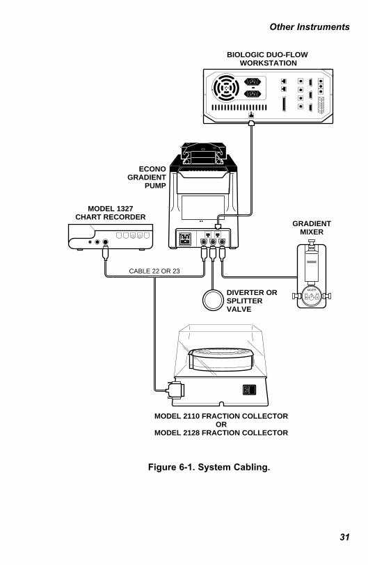
Figure 6-1. System Cabling.
Other Instruments
31
ECONOGRADIENT
PUMP
MODEL 2110 FRACTION COLLECTOROR
MODEL 2128 FRACTION COLLECTOR
MODEL 1327CHART RECORDER
CABLE 22 OR 23
GRADIENTMIXER
DIVERTER ORSPLITTER VALVE
MIXER
AB
BIOLOGIC DUO-FLOW WORKSTATION
4006161B.qxd 8/14/2003 8:09 AM Page 31

Figure 6-2. System Plumbing.
Other Instruments
32
ECONOGRADIENT PUMP
MODEL 2110FRACTION
COLLECTOR
MODEL 2128FRACTION
COLLECTOR
MODEL EG-1GRADIENTMONITOR
ECONO GRADIENT PUMP
MODEL EM-1UV OPTICS MODULE
GRADIENTMIXER
MIXER
AB
4006161B.qxd 8/14/2003 8:09 AM Page 32
7.0 CLEANING AND MAINTENANCE
The Econo Gradient Pump requires very little maintenance to assurereliable operation. The procedures outlined below will insuremaximum pump life:• Check tubing regularly for signs of cracking and wear. If any
exist, replace the tubing.• For optimal tubing life, use a slow to medium pump speed. To
increase throughput, increase tubing size to obtain the desiredoutput.
• When not in use, tubing should be removed from the pump toprevent deformation of the tubing. Remove the platen and relaxthe tubing by unhooking one end of the tubing from the tubingbracket.
• To prevent the formation of precipitates around the pump headand on the membrane key panel, promptly remove any spills.Clean with deionized water.
• If an auxiliary valve or the Gradient Mixer is used, rinse it withdeionized water after each use. Store them in 20% EtOH for long-term storage. Do not expose the valves to pressures greater than20psi.
• If using the pump at 4°C, leave the pump on (not necessarilyrunning) to mitigate condensation within the pump.
7.1 Fuse Replacement and Voltage Conversion
To replace a fuse, see Figure 7-1 and follow these steps:1. Disconnect the power cord from the unit.2. Remove the fuse drawer with a small-blade screwdriver or similar
tool. 3. Pull the fuse holder out of the fuse drawer and replace the fuses
with ones having the correct current rating. Use 0.40 A slow-blowfuses for 100/120 V operation; 0.20 A slow-blow fuses for220/240 V operation. The 0.20A fuses are packaged in a plasticbag and taped to the exterior of the pump.
Maintenance
33
4006161B.qxd 8/14/2003 8:09 AM Page 33

4. The fuse socket in the fuse drawer is removable. Turn the socketsuch that the correct voltage shows through the window.
5. Reinsert the fuse drawer into the power entry module, with thelocking tab to the left. Press gently until it snaps into place.
6. Insert the power cord plug into the power entry module. Plug thepower cord into a properly grounded outlet.
Figure 7-1. Fuse Replacement and Voltage Conversion.
Maintenance
34
110
220Power Entry Module
Voltage Selector
Window
Fuse Drawer
4006161B.qxd 8/14/2003 8:09 AM Page 34
8.0 TROUBLESHOOTING
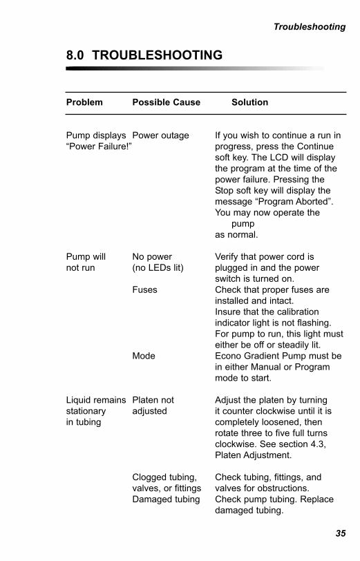
Problem Possible Cause Solution
Pump displays Power outage If you wish to continue a run in“Power Failure!” progress, press the Continue
soft key. The LCD will display the program at the time of the power failure. Pressing theStop soft key will display themessage “Program Aborted”.You may now operate the
pump as normal.
Pump will No power Verify that power cord is not run (no LEDs lit) plugged in and the power
switch is turned on.Fuses Check that proper fuses are
installed and intact.Insure that the calibrationindicator light is not flashing.For pump to run, this light musteither be off or steadily lit.
Mode Econo Gradient Pump must bein either Manual or Programmode to start.
Liquid remains Platen not Adjust the platen by turningstationary adjusted it counter clockwise until it is in tubing completely loosened, then
rotate three to five full turns clockwise. See section 4.3,Platen Adjustment.
Clogged tubing, Check tubing, fittings, and valves, or fittings valves for obstructions.Damaged tubing Check pump tubing. Replace
damaged tubing.
Troubleshooting
35
4006161B.qxd 8/14/2003 8:09 AM Page 35
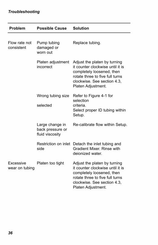
Problem Possible Cause Solution
Flow rate not Pump tubing Replace tubing.consistent damaged or
worn out
Platen adjustment Adjust the platen by turningincorrect it counter clockwise until it is
completely loosened, then rotate three to five full turns clockwise. See section 4.3,Platen Adjustment.
Wrong tubing size Refer to Figure 4-1 forselection
selected criteria.Select proper ID tubing withinSetup.
Large change in Re-calibrate flow within Setup.back pressure orfluid viscosity
Restriction on inlet Detach the inlet tubing andside Gradient Mixer. Rinse with
deionized water.
Excessive Platen too tight Adjust the platen by turningwear on tubing it counter clockwise until it is
completely loosened, then rotate three to five full turns clockwise. See section 4.3,Platen Adjustment.
Troubleshooting
36
4006161B.qxd 8/14/2003 8:09 AM Page 36

Problem Possible Cause Solution
Cannot Pump must be Insure that pump is stopped.calibrate stopped in order topump calibrate pump
RPM has been Select Flow Rate in screen 1 ofselected Setup.
Valves do not Pump is off Turn on the pump.respond or actuate Valve cabled to Mixer and/or Aux valve must be
wrong connector plugged in to its correct socket.
Chart recorder Pump is off Turn on the pump.or fraction collector does Valve cabled to Chart recorder or fractionnot respond wrong connector collector must be plugged in to
its correct connector.
Wrong fraction Setup screen 14 allows choicecollector specified of a Model 2110, 2128 or none.in setup Select the appropriate choice.
The proper Valves plugged See section 3.2 to plug valvesvalves do not into wrong port. into the correct port.appear on the display
EGP program Wrong device Ensure that only the fraction starts plugged into I/O collector or chart recorder isunexpectedly port plugged into the I/O port.
Ensure that pin #3 is notshorted.
Troubleshooting
37
4006161B.qxd 8/14/2003 8:09 AM Page 37
9.0 EMBEDDED FUNCTIONS
During a technical service call, you may be asked to perform taskswhich require you to press combinations of keys. These tasks aredefined below.
9.1 FIRMWARE CONFIRMATION
To check the version of firmware installed in the Econo GradientPump, power up the Econo Gradient Pump. During power up, thefirmware version is displayed. The checksum (CS) is also displayed.
9.2 RESET
To initiate a reset, press all three soft keys simultaneously and holdfor 3 seconds. This will reset all stored values to the factory defaults.
Embedded Functions
38
4006161B.qxd 8/14/2003 8:10 AM Page 38

APPENDIX ATECHNICAL SPECIFICATIONS
Number of channels 2Flow rate range (per channel) 0.002 - 20 ml/min (depending on
tubing diameter)Pump head speed 0.05 to 25 rpm maximumTubing diameter 0.19 mm ID to 3.2 mm ID;
maximum 1 mm wall thicknessSpeed adjustment increment 0.01 RPMSpeed stability 0.2% at 10 RPMSpeed accuracy 0.1% at 10 RPM
Maximum counterpressure 30 psi (2 kg/cm2 or bars)Motor DC speed controlled, 25 wattsLine voltage 90-132 VAC
180-264 VAC47-63 Hz
Dimensions 143 x 202 x 222 mm (W x D x H) with pumphead
Weight 3.5 kg Operating temperature 4 to 40 °CMaterial of construction polypropylene and other solvent
resistant plasticsRegulatory Compliance TÜV: EN61010-1:1993
CE: EN55011:1991 Class AEN50082-2:1997EN50081-2:1994ENV50204:1995
Specifications
39
4006161B.qxd 8/14/2003 8:10 AM Page 39

Gradient Mixer Range 0-100% BIncrement 1% B
Valve controlSV-3 Diverter Valve Waste and divert positions.Splitter Valve 0-100%
Fraction CollectorsModel 2110 Run, hold, pause, stopModel 2118 Run, hold, pause, stop
Chart RecorderModel 1327 Dual pen recorder, paper feed
start/stop, pen up/down
Specifications
40
4006161B.qxd 8/14/2003 8:10 AM Page 40

APPENDIX BCONNECTION TO OTHER INSTRUMENTS
The I/O connector on the rear panel of the pump is for the operationof the fraction collectors and chart recorder (see Figure 3-2). Outputsignals are TTL compatible. To use these signals for non-Bio-Raddevices, you must insure that the circuit external to the EconoGradient Pump does not draw more than 15 milliamperes of current.The following table describes the rear panel mini-DIN connectorpinouts for this I/O connector.
Table B-1. I/O mini-DIN Connector Pinouts
Selected Fraction CollectorPin# Name None 2110 2128
1 PS held HIGH held HIGH held HIGHstarts 1327 starts 1327 starts 1327
2 RUN --- 2.5 s held LOWLOW PULSE starts 2128resets 2110
3 FCNTRL1 held LOW held LOW held LOWstarts EGP starts EGP starts EGPprogram program program
4 START --- 120 ms LOW held LOWPULSE starts 2128toggles betweenstart and stop
Other Instruments
41
PIN #7
PIN #8
PIN #5
PIN #2
PIN #4
PIN #6
PIN #3
PIN #1
4006161B.qxd 8/14/2003 8:10 AM Page 41

Selected Fraction CollectorPin# Name None 2110 2128
5 no contact no contact no contact
6 ER/PD held LOW held LOW held LOWstarts 1327 starts 1327 starts 1327
7 Ground Signal Signal Signal Ground Ground Ground
8 no contact no contact no contact
Other Instruments
42
4006161B.qxd 8/14/2003 8:10 AM Page 42

APPENDIX C WARRANTY
The Econo Gradient Pump is warranted for one year against defectsin materials and workmanship. If any defects should occur during thiswarranty period, Bio-Rad will replace the defective parts withoutcharge. However, the following defects are specifically excluded:1. Defects caused by improper operation.2. Repair or modification done by anyone other than Bio-Rad
Laboratories or their authorized agent.3. Use with tubings or fittings not specified by Bio-Rad Laboratories
for use with this pump.4. Deliberate or accidental misuse.5. Damage caused by disaster.6. Damage due to use of improper solvent or sample.
This warranty does not apply to tubing, fittings, and fuses.
For inquiry or request for repair service, contact Bio-Rad Laboratoriesafter confirming the model and serial number of your instrument.
For Technical Service Call Your Local Bio-Rad Office or in the U.S.Call 1-800-4BIORAD (1-800-424-6723).
Warranty
43
4006161B.qxd 8/14/2003 8:10 AM Page 43
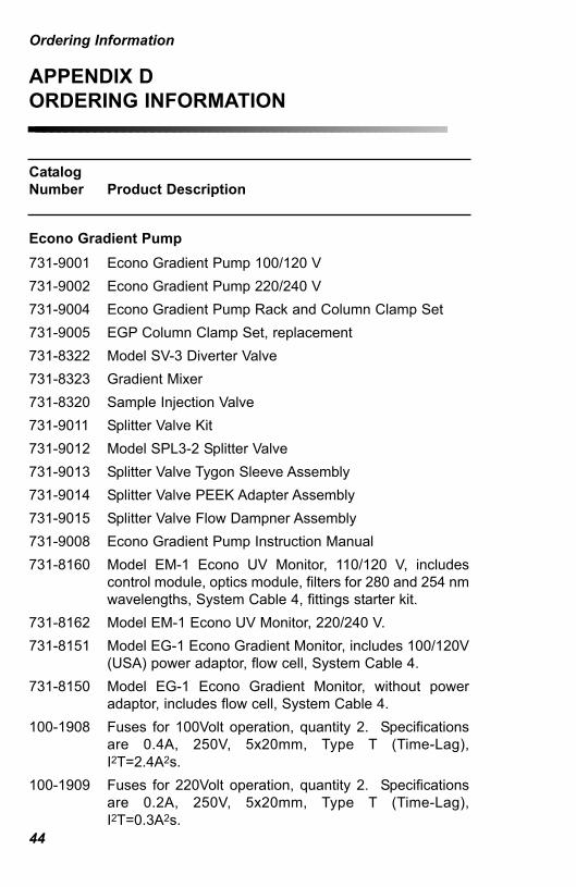
APPENDIX DORDERING INFORMATION
CatalogNumber Product Description
Econo Gradient Pump731-9001 Econo Gradient Pump 100/120 V731-9002 Econo Gradient Pump 220/240 V731-9004 Econo Gradient Pump Rack and Column Clamp Set731-9005 EGP Column Clamp Set, replacement731-8322 Model SV-3 Diverter Valve731-8323 Gradient Mixer731-8320 Sample Injection Valve731-9011 Splitter Valve Kit731-9012 Model SPL3-2 Splitter Valve731-9013 Splitter Valve Tygon Sleeve Assembly731-9014 Splitter Valve PEEK Adapter Assembly731-9015 Splitter Valve Flow Dampner Assembly731-9008 Econo Gradient Pump Instruction Manual731-8160 Model EM-1 Econo UV Monitor, 110/120 V, includes
control module, optics module, filters for 280 and 254 nmwavelengths, System Cable 4, fittings starter kit.
731-8162 Model EM-1 Econo UV Monitor, 220/240 V.731-8151 Model EG-1 Econo Gradient Monitor, includes 100/120V
(USA) power adaptor, flow cell, System Cable 4.731-8150 Model EG-1 Econo Gradient Monitor, without power
adaptor, includes flow cell, System Cable 4.100-1908 Fuses for 100Volt operation, quantity 2. Specifications
are 0.4A, 250V, 5x20mm, Type T (Time-Lag),I2T=2.4A2s.
100-1909 Fuses for 220Volt operation, quantity 2. Specificationsare 0.2A, 250V, 5x20mm, Type T (Time-Lag),I2T=0.3A2s.
Ordering Information
44
4006161B.qxd 8/14/2003 8:10 AM Page 44

CatalogNumber Product Description
Tubing and Accessories731-8210 Silicone Tubing, 0.8 mm ID, 0.8 mm wall, 10 m731-8211 Silicone Tubing, 1.6 mm ID, 0.8 mm wall, 10 m731-8212 Silicone Tubing, 3.2 mm ID, 0.8 mm wall, 10 m731-8213 Tygon tubing, 0.51 mm ID, 0.8 mm wall, 10 m731-8214 Tygon Tubing, 0.8 mm ID, 0.8 mm wall, 10 m731-8215 Tygon Tubing, 1.6 mm ID, 0.8 mm wall, 10 m731-8207 PharMed Tubing, 0.8 mm ID, 1.0 mm wall, 10 m731-8208 PharMed Tubing, 1.6 mm ID, 1.0 mm wall, 10 m731-8209 PharMed Tubing, 3.2 mm ID, 1.0 mm wall, 10 m731-9007 Peristaltic Pumphead Tubing, includes two precut
lengths each of Pharmed tubing, 0.8, 1.6, and 3.2 mm ID.731-8240 Silicone Tubing Kit, 0.8 mm ID, 20 precut lengths and 4
sets of fittings.731-8241 Silicone Tubing Kit, 1.6 mm ID, 20 precut lengths and 4
sets of fittings.731-8242 Silicone Tubing Kit, 3.2 mm ID, 20 precut lengths and 4
sets of fittings.731-8247 PharMed Tubing Kit, 0.8 mm ID, 20 precut lengths and 4
sets of fittings.731-8248 PharMed Tubing Kit, 1.6 mm ID, 20 precut lengths and 4
sets of fittings.731-8249 PharMed Tubing Kit, 3.2 mm ID, 20 precut lengths and 4
sets of fittings.731-8220 Low Pressure Fittings Kit, includes over 250 male and
female luer connectors, 2- and 3-way stopcocks, andtubing connectors.
PharMed and Tygon are the registered trademarks of the Norton Company.
Ordering Information
45
4006161B.qxd 8/14/2003 8:10 AM Page 45

CatalogNumber Product Description
731-9006 Low Pressure, Small Fittings Kit. Contains a subset ofthe fittings found in catalog # 731-8220, including barb-to-female and male luer for 0.8, 1.6, and 3.2 mm tubing,slip fittings, and both female and male luer plugs.
Cables731-8264 System Cable 4, 8-pin mini-DIN to banana cable. To
connect Econo UV Monitor or Econo Gradient Monitor tothe Model 1327 Chart Recorder.
731-9009 System Cable 23, Y-cable. To connect both a Model2128 Fraction Collector and Model 1327 Chart Recorderto the Econo Gradient Pump.
731-9010 System Cable 22, Y-cable. To connect both a Model 2110Fraction Collector and Model 1327 Chart Recorder to theEcono Gradient Pump.
750-0650 System Cable 17 (bus cable), 4 feet (1.2 m)750-0651 System Cable 18 (bus cable), 12 feet (3.7 m)750-0652 System Cable 19 (bus cable), 30 feet (9.2 m)750-0655 System Cable 21 (bus cable), 100 feet (30 m)
Model 2110 Fraction Collector731-8122 Model 2110 Fraction Collector, 100/120 V731-8120 Model 2110 Fraction Collector, 220/240 V
Model 2128 Fraction Collector731-8123 Model 2128 Fraction Collector, 100/120 V731-8124 Model 2128 Fraction Collector, 220/240 V
Bio-Rad sells a complete line of integrated chromatography systemsfor protein purification. For more information on the BioLogic Systemfamily of products, contact your local Bio-Rad representative.
Ordering Information
46
4006161B.qxd 8/14/2003 8:10 AM Page 46

Life ScienceGroup
Web site www.bio-rad.com USA (800) 4BIORAD Australia 02 9914 2800 Austria (01) 877 89 01 Canada (905) 712-2771 45 44 52-1000 Finland 089 318 84-177Hong Kong 852-2789-3300 India Israel 03 951 4124Italy 34 91 590 5200 03-5811-6270 Korea 82-2-3473-4460Latin America Mexico 52 5 534 2552 to 54The Netherlands 0318-540666 64-9-4152280 Norway 47-23-38-41-30Russia 7 095 979 98 00 Singapore 65-2729877 Spain 34-91-590-5200Sweden 46 (0)8-55 51 27 00 Switzerland061-717-9555 United Kingdom 0800-181134
00-000 0000 Sig 1200Bulletin 0000 US/EG Rev A
Bio-RadLaboratories
4006161 Rev B
4006161B.qxd 8/14/2003 8:10 AM Page 47