ecm section page 1 of 269 · engine coolant temperature >= 59.96 °c and engine coolant...
TRANSCRIPT

Component / Fault Monitor Strategy Primary Malfunction Secondary Time MILSystem Code Description Criteria Parameters Required Illum.
Crankshaft toCamshaft Correlation
P0016 Detects a shift of the camshaftangle by monitoring theaverage offset angle.
average value of camshaft offset < -25.00 degrees Engine backward rotation detected = FALSE - B
OR andaverage value of camshaft offset > 25.00 degrees NO pending or confirmed DTCs = see sheet inhibit
tables-
andIgnition on = TRUE -andbasic enable conditions met: = see sheet enable
tables-
HO2S Heater ControlCircuit Bank 1 Sensor1 Circuit
P0030 Monitoring the HO2S heatercontrol circuit for open circuitfailures
Voltage low during driver off state(indicates open circuit)
= Open Circuit:≥200 K Ωimpedancebetween ECU pinand load
- Ignition on = TRUE - B
HO2S heater control commanded on = FALSE -basic enable conditions met: = TRUE -
HO2S Heater ControlCircuit Bank 1 Sensor1 Circuit Low
P0031 Monitoring the HO2S heatercontrol circuit for circuit lowfailures
Voltage low during driver off state(indicates short-to-ground)
= Short to ground:≤ 0.5 Ωimpedancebetween signaland controllerground
- Ignition on = TRUE - B
basic enable conditions met: = TRUE -
Threshold EnableLogic and Value Conditions
fail conditionsexists for
more than 2events
testperformed
continuously0.01 s rate
fault exists formore than 5sec; monitorruns at 0.1 swhen enable
conditions aremet
fault exists formore than 5sec; monitorruns at 0.1 swhen enable
conditions aremet
15 OBDG04 ECM Summary Tables
ECM Section Page 1 of 269

Component / Fault Monitor Strategy Primary Malfunction Secondary Time MILSystem Code Description Criteria Parameters Required Illum.
Threshold EnableLogic and Value Conditions
HO2S Heater ControlCircuit Bank 1 Sensor1 Circuit High
P0032 Monitoring the HO2S heatercontrol circuit for circuit highfailures
Voltage high during driver on state(indicates short to power)
= Short to power: ≤ 0.5 Ωimpedancebetween signaland controllerpower
- HO2S heater control commanded on = TRUE B
Ignition on = TRUE -basic enable conditions met: = TRUE -
Turbocharger BoostControl Position NotLearned
P003A Detects in range vane positionerrors during a vane sweepinitiated to learn minimum andmaximum vane positionvalues.
Path 1: injection quantity >= 0.00 mm^3/rev
B
mean offset learned value at fully closedvalve position
< 70.00 % and
or injection quantity <= 24 mm^3/rev
mean offset learned value at fully closedvalve position
> 110.00 % and
acceleration pedal sensor <= 1.00 %andEngine Speed >= 575.00 rpmandEngine Speed <= 1075.00 rpmandVehicle speed >= 0.00 mphandVehicle speed <= 3.11 mphandBattery voltage >= 11.00 Vandengine coolant temperature >= 59.96 °Candengine coolant temperature <= 127.96 °CandBarometric pressure >= 65.00 kPaandBarometric pressure <= 105.00 kPaand
fail conditionsexists for 0.01
smonitor runsonce per tripwith 0.01 s
rate wheneverenable
conditions aremet
fault exists formore than 5sec; monitorruns at 0.1 swhen enable
conditions aremet
15 OBDG04 ECM Summary Tables
ECM Section Page 2 of 269

Component / Fault Monitor Strategy Primary Malfunction Secondary Time MILSystem Code Description Criteria Parameters Required Illum.
Threshold EnableLogic and Value Conditions
time since start > 10.08 secandRich idle regeneration = inactive -andAdaption is finished for this driving cycle = inactive -
andvalve closed = TRUE -andturbocharger offset adaption timer >= 0.50 secandNo Pending or Confirmed DTCs: = see sheet inhibit
tables-
andbasic enable conditions met: = see sheet enable
tables-
Path 2: injection quantity >= 0.00 mm^3/rev
time taken to learn the mean offsetlearned value at fully closed valveposition
> 30.00 sec and
injection quantity <= 24 mm^3/rev
andValue acceleration pedal sensor 1 <= 1.00 %andEngine Speed >= 575.00 rpmandEngine Speed <= 1075.00 rpmandVehicle speed >= 0.00 mphandVehicle speed <= 3.11 mphandBattery voltage >= 11.00 Vandengine coolant temperature >= 59.96 °Candengine coolant temperature <= 127.96 °Cand
fail conditionsexists for 0.01
smonitor runsonce per tripwith 0.01 s
rate wheneverenable
conditions aremet
15 OBDG04 ECM Summary Tables
ECM Section Page 3 of 269

Component / Fault Monitor Strategy Primary Malfunction Secondary Time MILSystem Code Description Criteria Parameters Required Illum.
Threshold EnableLogic and Value Conditions
Barometric pressure >= 65.00 kPaandBarometric pressure <= 105.00 kPaandtime since start > 10.08 secandRich idle regeneration = inactive -andAdaption is finished for this driving cycle = inactive -
andvalve closed = TRUE -andturbocharger offset adaption timer >= 0.50 secandNo Pending or Confirmed DTCs: = see sheet inhibit
tables-
andbasic enable conditions met: = see sheet enable
tables-
Turbocharger BoostControl Circuit
P0045 Diagnoses the TurbochargerBoost Control low side drivercircuit for circuit faults.
Voltage low during driver off state(indicates open circuit)
= Open Circuit:200 K impedancebetween ECU pinand load
- battery voltage > 11.00 V B
for
time > 3.00 secandstarter is active cranking = FALSE -andbasic enable conditions met: = see sheet enable
tables-
fail conditionsexists for 3.0
smonitor runswith 0.01 s
rate wheneverenable
conditions aremet
15 OBDG04 ECM Summary Tables
ECM Section Page 4 of 269

Component / Fault Monitor Strategy Primary Malfunction Secondary Time MILSystem Code Description Criteria Parameters Required Illum.
Threshold EnableLogic and Value Conditions
Diagnoses the TurbochargerBoost Control low side drivercircuit for driver overtemperature faults.
The ECM detects that the commandedstate of the driver and the actual state ofthe control circuit do not match and theIC maximum temperature has beenexceeded
battery voltage > 11.00 V
for
time > 3.00 secandstarter is active cranking = FALSE -andbasic enable conditions met: = see sheet enable
tables-
Turbocharger BoostControl Circuit LowVoltage
P0047 Diagnoses the TurbochargerBoost Control low side drivercircuit for circuit faults.
Voltage low during driver off state(indicates short-to-ground)
= Short to ground: 0.5
impedancebetween signaland controllerground
- battery voltage > 11.00 V B
for
time > 3.00 secandstarter is active cranking = FALSE -andbasic enable conditions met: = see sheet enable
tables-
Turbocharger BoostControl Circuit HighVoltage
P0048 Diagnoses the TurbochargerBoost Control low side drivercircuit for circuit faults.
Voltage high during driver on state(indicates short to power)
= Short to power: ≤ 0.5 Ωimpedancebetween signaland controllerpower
battery voltage > 11.00 V B
for
fail conditionsexists for 0.5
smonitor runswith 0.01 s
rate wheneverenable
conditions aremet
fail conditionsexists for 3.0
smonitor runswith 0.01 s
rate wheneverenable
conditions aremet
fail conditionsexists for 1.0
smonitor runswith 0.01 s
rate wheneverenable
conditions aremet
15 OBDG04 ECM Summary Tables
ECM Section Page 5 of 269

Component / Fault Monitor Strategy Primary Malfunction Secondary Time MILSystem Code Description Criteria Parameters Required Illum.
Threshold EnableLogic and Value Conditions
time > 3.00 secandstarter is active cranking = FALSE -andbasic enable conditions met: = see sheet enable
tables-
HO2S HeaterResistance Bank1Sensor 1
P0053 A/F sensor heating controlmonitoring, which monitors theheater control of the A/Fsensor. If the temperature ofthe A/F sensor, based on themeasured sensor internalresistance, exceeds athreshold a fault is detected
Temperature of A/F sensor (based onsensor internal resistance)
> 823.96 °C Engine is running (please see thedefinition)
= TRUE - B
Decel fuel cut-off (DFCO) = FALSE -for time >= 5.00 sec
(duty cycle value during sensor heat-up >= 90.25 %
for time >= 19.50 secorTemperature of A/F sensor (based onsensor internal resistance)
> 804.96 °C
andStatus bit for valid A/F sensor innerResistance (see parameter definitiontable)
= TRUE -
)Status bit for heater control disabled(False = heater control active, True =heater control not active)
= FALSE -
A/F sensor error status bit (seeparameter definition table)
= FALSE -
NO Pending or Confirmed DTCs: = see sheet inhibittables
-
basic enable conditions met: = see sheet enabletables
-
fault exists formore than 30sec; monitorruns at 0.1 swhen enable
conditions aremet
15 OBDG04 ECM Summary Tables
ECM Section Page 6 of 269

Component / Fault Monitor Strategy Primary Malfunction Secondary Time MILSystem Code Description Criteria Parameters Required Illum.
Threshold EnableLogic and Value Conditions
A/F sensor heating controlmonitoring, which monitors theheater control of the A/Fsensor. If the temperature ofthe A/F sensor, based on themeasured sensor internalresistance, is less than athreshold a fault is detected
Temperature of A/F sensor (based onsensor internal resistance)
< 805.96 °C Engine is running (please see thedefinition)
= TRUE -
Decel fuel cut-off (DFCO) = FALSE -for time >= 5.00 sec
(duty cycle value during sensor heat-up >= 90.25 %
for time >= 19.50 secorTemperature of A/F sensor (based onsensor internal resistance)
> 804.96 °C
andStatus bit for valid A/F sensor innerResistance (see parameter definitiontable)
= TRUE -
)Status bit for heater control disabled(False = heater control active, True =heater control not active)
= FALSE -
A/F sensor error status bit (seeparameter definition table)
= FALSE -
NO Pending or Confirmed DTCs: = see sheet inhibittables
-
basic enable conditions met: = see sheet enabletables
-
CAC TemperatureSensor Circuit LowVoltage
P007C Detects a CAC temperaturesensor circuit short to ground.
CAC downstream temperature sensorvoltage
< 0.11 V ignition on = TRUE - A
same as anddownstream CAC temperature > 199.96 °C basic enable conditions met: = see sheet enable
tables-
andNO Pending or Confirmed DTCs: = see sheet inhibit
tables-
fault exists formore than 60sec; monitorruns at 0.1 swhen enable
conditions aremet
fail conditionsexists for 5 s
testperformed
continuously0.1 s rate
15 OBDG04 ECM Summary Tables
ECM Section Page 7 of 269

Component / Fault Monitor Strategy Primary Malfunction Secondary Time MILSystem Code Description Criteria Parameters Required Illum.
Threshold EnableLogic and Value Conditions
CAC TemperatureSensor Circuit HighVoltage
P007D Detects a CAC temperaturesensor circuit short to highvoltage or a sensor opencircuit
CAC downstream temperature sensorvoltage
> 4.94 V ignition on = TRUE - A
same as anddownstream CAC temperature < -50.04 °C basic enable conditions met: = see sheet enable
tables-
andNO Pending or Confirmed DTCs: = see sheet inhibit
tables-
Fuel Rail Pressure[FRP] Too Low
P0087 Measured rail pressure ischecked against desired railpressure to detect low railpressure conditions.
rail pressure deviation from setpointcalculated out of difference betweendesired and actual value (see Look-Up-Table #63)
> 11000 to 80000 kPa state machine rail pressure control equalto metering unit control mode
= TRUE - B
andbasic enable conditions met: see sheet enable
tables-
andmetering unit actuator test active = FALSE -andNO Pending or Confirmed DTCs: see sheet inhibit
tables-
rail pressure deviation from setpointcalculated out of difference betweendesired and actual value (see Look-Up-Table #66)
> 11000 to 80000 kPa (
state machine rail pressure control equalto pressure control valve
= TRUE -
orstate machine rail pressure control equalcoupled pressure control (rail pressure iscontrolled by metering unit and pressurecontrol valve)
= TRUE -
)and
fail conditionsexists for 5 s
testperformed
continuously0.1 s rate
fail conditionsexists for 8 smonitor runswith 0.02 s
rate wheneverenable
conditions aremet
fail conditionsexists for 8 smonitor runswith 0.02 s
rate wheneverenable
conditions aremet
15 OBDG04 ECM Summary Tables
ECM Section Page 8 of 269

Component / Fault Monitor Strategy Primary Malfunction Secondary Time MILSystem Code Description Criteria Parameters Required Illum.
Threshold EnableLogic and Value Conditions
basic enable conditions met: see sheet enabletables
-
andmetering unit actuator test active = FALSE -andNO Pending or Confirmed DTCs: see sheet inhibit
tables-
Fuel Rail Pressure[FRP] Too High
P0088 Measured rail pressure ischecked against desired railpressure to detect high railpressure conditions.
rail pressure deviation from setpointcalculated out of difference betweendesired and actual value (see Look-Up-Table #64)
< -80000 to -18000 kPa current injection quantity > 4.00 mm^3/rev
B
andfuel temperature > -40.04 °Candstate machine rail pressure control equalto metering unit control mode
= TRUE -
andbasic enable conditions met: see sheet enable
tables-
andmetering unit actuator test active = FALSE -andNO Pending or Confirmed DTCs: see sheet inhibit
tables-
rail pressure deviation from setpointcalculated out of difference betweendesired and actual value
< -18000.00 kPa (
state machine rail pressure control equalto pressure control valve
= TRUE -
orstate machine rail pressure control equalcoupled pressure control (rail pressure iscontrolled by metering unit and pressurecontrol valve)
= TRUE -
)and
fail conditionsexists for 8 smonitor runswith 0.02 s
rate wheneverenable
conditions aremet
fail conditionsexists for 8 smonitor runswith 0.02 s
rate wheneverenable
conditions aremet
15 OBDG04 ECM Summary Tables
ECM Section Page 9 of 269

Component / Fault Monitor Strategy Primary Malfunction Secondary Time MILSystem Code Description Criteria Parameters Required Illum.
Threshold EnableLogic and Value Conditions
basic enable conditions met: see sheet enabletables
-
andNO Pending or Confirmed DTCs: see sheet inhibit
tables-
Fuel PressureRegulator 1 ControlCircuit/Open
P0090 Diagnoses the Fuel PressureRegulator 1 low side drivercircuit for circuit faults.
Voltage low during driver off state(indicates open circuit)
= Open Circuit:200 K impedancebetween ECU pinand load
- battery voltage > 11.00 V A
for
time > 3.00 secandignition on = TRUE -andbasic enable conditions met: = see sheet enable
tables-
NO Pending or Confirmed DTCs: = see sheet inhibittables
-
Diagnoses the Fuel PressureRegulator 1 low side drivercircuit for circuit faults.
The ECM detects that the commandedstate of the driver and the actual state ofthe control circuit do not match.
battery voltage > 11.00 V
for
time > 3.00 secandignition on = TRUE -andbasic enable conditions met: = see sheet enable
tables-
NO Pending or Confirmed DTCs: = see sheet inhibittables
-
fail conditionsexists for 0.22
smonitor runswith 0.01 s
rate wheneverenable
conditions aremet
fail conditionsexists for 0.2
smonitor runswith 0.01 s
rate wheneverenable
conditions aremet
15 OBDG04 ECM Summary Tables
ECM Section Page 10 of 269

Component / Fault Monitor Strategy Primary Malfunction Secondary Time MILSystem Code Description Criteria Parameters Required Illum.
Threshold EnableLogic and Value Conditions
Fuel PressureRegulator 1 ControlCircuit Low
P0091 Diagnoses the Fuel PressureRegulator 1 low side drivercircuit for circuit faults.
Voltage low during driver off state(indicates short-to-ground)
= Short to ground: 0.5
impedancebetween signaland controllerground
- battery voltage > 11.00 V A
for
time > 3.00 secandignition on = TRUE -andbasic enable conditions met: = see sheet enable
tables-
NO Pending or Confirmed DTCs: = see sheet inhibittables
-
Fuel PressureRegulator 1 ControlCircuit High
P0092 Diagnoses the Fuel PressureRegulator 1 low side drivercircuit for circuit faults.
Voltage high during driver on state(indicates short to power)
= Short to power: ≤ 0.5 Ωimpedancebetween signaland controllerpower
- battery voltage > 11.00 V A
for
time > 3.00 secandignition on = TRUE -andbasic enable conditions met: = see sheet enable
tables-
NO Pending or Confirmed DTCs: = see sheet inhibittables
-
fail conditionsexists for 0.28
smonitor runswith 0.01 s
rate wheneverenable
conditions aremet
fail conditionsexists for 0.22
smonitor runswith 0.01 s
rate wheneverenable
conditions aremet
15 OBDG04 ECM Summary Tables
ECM Section Page 11 of 269

Component / Fault Monitor Strategy Primary Malfunction Secondary Time MILSystem Code Description Criteria Parameters Required Illum.
Threshold EnableLogic and Value Conditions
Intake AirTemperature Sensor 2Circuit Low
P0097 Detects a low PWM frequencyfrom the humidity temperaturesensor, indicating an OOR lowcondition on the humiditytemperature sensor circuit
Humidity Temperature sensor frequency(Intake air temperature sensor 2)
< 28.03 Hz Engine Running (please see thedefinition)
= TRUE - B
same as andhumidity temperature < -50.04 degC following conditions for time: > 1.00 sec
battery voltage > 11.00 Vbattery voltage < 655.34 V
andbasic enable conditions met: = see sheet enable
tables-
andno pending or confirmed DTCs = see sheet inhibit
tables-
The internal ECM PWM circuitdriver detects either a dutycycle which has not beenreceived or the maximumperiod has been exceeded,indicating short low conditionon the humidity sensor circuit.
Internal ECM PWM circuit low voltage = TRUE - Engine Running (please see thedefinition)
= TRUE -
and andECM PWM circuit maximum perioddetected
= TRUE - following conditions for time: > 1.00 sec
or battery voltage > 11.00 VInternal ECM PWM period not received = TRUE - battery voltage < 655.34 V
andbasic enable conditions met: = see sheet enable
tables-
andno pending or confirmed DTCs = see sheet inhibit
tables-
fail conditionsexists for 3.0
stest
performedcontinuously
with 0.1 s rate
fail conditionsexists for 3.0
stest
performedcontinuously
with 0.1 s rate
15 OBDG04 ECM Summary Tables
ECM Section Page 12 of 269

Component / Fault Monitor Strategy Primary Malfunction Secondary Time MILSystem Code Description Criteria Parameters Required Illum.
Threshold EnableLogic and Value Conditions
Intake AirTemperature Sensor 2Circuit High
P0098 Detects a high PWMfrequency from the humiditytemperature sensor, indicatingan OOR high condition on thehumidity temperature sensorcircuit
Humidity Temperature sensor frequency(Intake air temperature sensor 2)
> 353.76 Hz Engine Running (please see thedefinition)
= TRUE - B
same as andhumidity temperature > 129.96 degC following conditions for time: > 1.00 sec
battery voltage > 11.00 Vbattery voltage < 655.34 V
andbasic enable conditions met: = see sheet enable
tables-
andno pending or confirmed DTCs = see sheet inhibit
tables-
The internal ECM PWM circuitdriver detects either a dutycycle which has not beenreceived or the maximumperiod has been exceeded,indicating short high conditionon the humidity sensor circuit.
Internal ECM PWM circuit high voltage = TRUE - Engine Running (please see thedefinition)
= TRUE -
and andECM PWM circuit maximum perioddetected
= TRUE - following conditions for time: > 1.00 sec
or battery voltage > 11.00 VInternal ECM PWM period not received = TRUE - battery voltage < 655.34 V
andbasic enable conditions met: = see sheet enable
tables-
andno pending or confirmed DTCs = see sheet inhibit
tables-
fail conditionsexists for 3.0
stest
performedcontinuously
with 0.1 s rate
fail conditionsexists for 3.0
stest
performedcontinuously
with 0.1 s rate
15 OBDG04 ECM Summary Tables
ECM Section Page 13 of 269

Component / Fault Monitor Strategy Primary Malfunction Secondary Time MILSystem Code Description Criteria Parameters Required Illum.
Threshold EnableLogic and Value Conditions
Fuel PressureRegulator 1 HighControl Circuit LowVoltage
P00C9 Diagnoses the Fuel PressureRegulator 1 high side drivercircuit for circuit faults.
Voltage low during driver on state(indicates short to ground)
= Short to ground: ≤ 0.5 Ωimpedancebetween signaland controllerground
- ignition on = TRUE - A
andbasic enable conditions met: = see sheet enable
tables-
Fuel Rail PressureRegulator 1 HighControl Circuit HighVoltage
P00CA Diagnoses the Fuel PressureRegulator 1 high side drivercircuit for circuit faults.
Voltage high during driver off state(indicates short to power )
= Short to power: ≤0.5 Ω impedancebetween signaland controllerpower
- ( A
engine speed = 0 rpmorengine post drive/ afterun = TRUE -)and -NO Pending or Confirmed DTCs: = see sheet inhibit
tables-
fortime > 7.00 sec
andbasic enable conditions met: = see sheet enable
tables-
fail conditionsexists for 0.3smonitor runswith 0.01 s
rate wheneverenable
conditions aremet
fail conditionsexists for 0.1
smonitor runs
with 0.1 s ratewhenever
enableconditions are
met
15 OBDG04 ECM Summary Tables
ECM Section Page 14 of 269
Component / Fault Monitor Strategy Primary Malfunction Secondary Time MILSystem Code Description Criteria Parameters Required Illum.
Threshold EnableLogic and Value Conditions
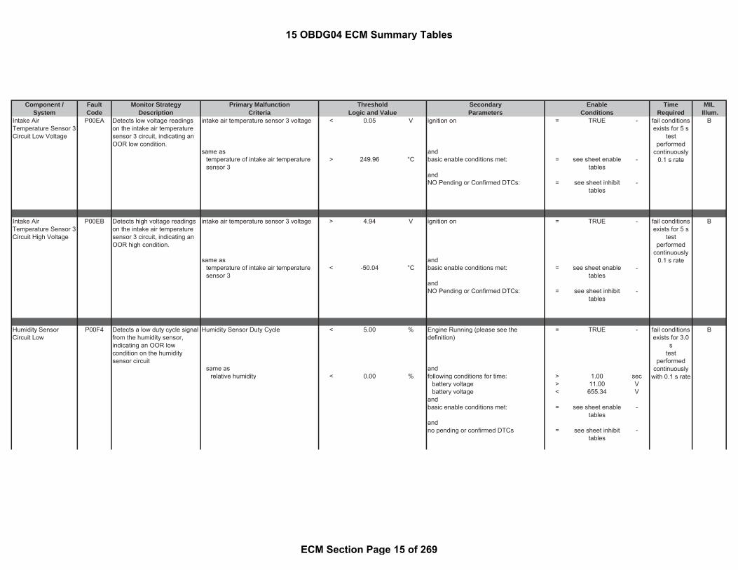
Intake AirTemperature Sensor 3Circuit Low Voltage
P00EA Detects low voltage readingson the intake air temperaturesensor 3 circuit, indicating anOOR low condition.
intake air temperature sensor 3 voltage < 0.05 V ignition on = TRUE - B
same as andtemperature of intake air temperaturesensor 3
> 249.96 °C basic enable conditions met: = see sheet enabletables
-
andNO Pending or Confirmed DTCs: = see sheet inhibit
tables-
Intake AirTemperature Sensor 3Circuit High Voltage
P00EB Detects high voltage readingson the intake air temperaturesensor 3 circuit, indicating anOOR high condition.
intake air temperature sensor 3 voltage > 4.94 V ignition on = TRUE - B
same as andtemperature of intake air temperaturesensor 3
< -50.04 °C basic enable conditions met: = see sheet enabletables
-
andNO Pending or Confirmed DTCs: = see sheet inhibit
tables-
Humidity SensorCircuit Low
P00F4 Detects a low duty cycle signalfrom the humidity sensor,indicating an OOR lowcondition on the humiditysensor circuit
Humidity Sensor Duty Cycle < 5.00 % Engine Running (please see thedefinition)
= TRUE - B
same as andrelative humidity < 0.00 % following conditions for time: > 1.00 sec
battery voltage > 11.00 Vbattery voltage < 655.34 V
andbasic enable conditions met: = see sheet enable
tables-
andno pending or confirmed DTCs = see sheet inhibit
tables-
fail conditionsexists for 5 s
testperformed
continuously0.1 s rate
fail conditionsexists for 5 s
testperformed
continuously0.1 s rate
fail conditionsexists for 3.0
stest
performedcontinuously
with 0.1 s rate
15 OBDG04 ECM Summary Tables
ECM Section Page 15 of 269

Component / Fault Monitor Strategy Primary Malfunction Secondary Time MILSystem Code Description Criteria Parameters Required Illum.
Threshold EnableLogic and Value Conditions
The internal ECM PWM circuitdriver detects either a dutycycle which has not beenreceived or the maximumperiod has been exceeded,indicating short low conditionon the humidity sensor circuit.
Internal ECM PWM circuit low voltage = TRUE - Engine Running (please see thedefinition)
= TRUE -
and andECM PWM circuit maximum perioddetected
= TRUE - following conditions for time: > 1.00 sec
or battery voltage > 11.00 VInternal ECM PWM period not received = TRUE - battery voltage < 655.34 V
andbasic enable conditions met: = see sheet enable
tables-
andno pending or confirmed DTCs = see sheet inhibit
tables-
Humidity SensorCircuit High
P00F5 Detects a high duty cyclesignal from the humiditysensor, indicating an OORhigh condition on the humiditysensor circuit
Humidity Sensor Duty Cycle > 95.00 % Engine Running (please see thedefinition)
= TRUE - B
same as andrelative humidity > 100.00 % following conditions for time: > 1.00 sec
battery voltage > 11.00 Vbattery voltage < 655.34 V
andbasic enable conditions met: = see sheet enable
tables-
andno pending or confirmed DTCs = see sheet inhibit
tables-
fail conditionsexists for 3.0
stest
performedcontinuously
with 0.1 s rate
fail conditionsexists for 3.0
stest
performedcontinuously
with 0.1 s rate
15 OBDG04 ECM Summary Tables
ECM Section Page 16 of 269

Component / Fault Monitor Strategy Primary Malfunction Secondary Time MILSystem Code Description Criteria Parameters Required Illum.
Threshold EnableLogic and Value Conditions
The internal ECM PWM circuitdriver detects either a dutycycle which has not beenreceived or the maximumperiod has been exceeded,indicating short high conditionon the humidity sensor circuit.
Internal ECM PWM circuit high voltage = TRUE - Engine Running (please see thedefinition)
= TRUE -
and andECM PWM circuit maximum perioddetected
= TRUE - following conditions for time: > 1.00 sec
or battery voltage > 11.00 VInternal ECM PWM period not received = TRUE - battery voltage < 655.34 V
andbasic enable conditions met: = see sheet enable
tables-
andno pending or confirmed DTCs = see sheet inhibit
tables-
Humidity SensorCircuit Intermittent /Erratic
P00F6 The humidity signalperformance monitor monitorsthe humidity signal delta in adefined time interval. The sumof these signal delta's over anumber of time intervals iscompared to a threshold.
Cumulative Humidity Sensor signal delta >= 50.00 % Engine Running (please see thedefinition)
= TRUE - B
accumulated over a defined timeinterval
> 5.00 counts and
same as no pending or confirmed DTCs = see sheet inhibittables
-
accumulated over time > 0.10 sec andbasic enable conditions met: = see sheet enable
tables-
fail conditionsexists for 3.0
stest
performedcontinuously
with 0.1 s rate
fail conditionsexists for 4
out of 5windows (xout of y),
test isperformed
continuouslywith 0.1 s rate
15 OBDG04 ECM Summary Tables
ECM Section Page 17 of 269

Component / Fault Monitor Strategy Primary Malfunction Secondary Time MILSystem Code Description Criteria Parameters Required Illum.
Threshold EnableLogic and Value Conditions
Mass Air Flow (MAF)Sensor Performance
P0101 Detects skewed MAF sensorby comparing measured MAFto calculated expected MAFbased on volumetric efficiencyof the engine
Path 1: B
ratio of measured air flow / desired airflow < [(a) - (b)] * (c) *
(d) ambient pressure > 74.80 kPa
where and(a) Engine load dependent MAP forcalculating lower threshold (see Look-Up-Table #1)
= 0.8 to 0.85 - engine coolant temperature >= 69.96 °C
(b) Air temperature dependentcorrection factor curve = 0 - and
(c) Engine temperature basedcorrection factor curve = 1 - engine coolant temperature <= 125.96 °C
(d) Barometric pressure basedcorrection factor curve = 1 - and
gradient of the charge-air temperature >= -2.00 °C/secor and
gradient of the charge-air temperature <= 2.00 °C/secPath 2: and
ratio of measured air flow / desired airflow > (e) + (f) - (
where Engine Running (please see thedefintion) = TRUE -
(e) Engine load dependent MAP forcalculating higher threshold = 1.20 - for
(f) Air temperature dependentcorrection factor curve = 0 - time since start > 90.00 sec
)andcontrol value of the throttle valve >= -400.00 %andcontrol value of the throttle valve <= 5.00 %and
setpoint value of Variable swirl actuator >= -400.00 %
and
setpoint value of Variable swirl actuator <= 399.99 %
and(
fail conditionsexists for 10 smonitor runswith 0.01 s
rate wheneverenable
conditions aremet
15 OBDG04 ECM Summary Tables
ECM Section Page 18 of 269

Component / Fault Monitor Strategy Primary Malfunction Secondary Time MILSystem Code Description Criteria Parameters Required Illum.
Threshold EnableLogic and Value Conditions
setpoint valve position of exhaust-gasrecirculation
>= -400.00 %
andsetpoint valve position of exhaust-gasrecirculation
<= 2.00 %
fortime > 3.00 sec
)andAir System Control is not disabled = TRUE -and(
NO Pending or Confirmed DTCs: = see sheet inhibittables
andactual valve position of exhaust-gasrecirculation >= -400.00 %
andactual valve position of exhaust-gasrecirculation <= 2.00 %
fortime > 3.00 sec)and
injection quantity >= -20.00 mm^3/rev
and
injection quantity <= 150.00 mm^3/rev
andair pressure in the induction volume >= 74.80 kPaandair pressure in the induction volume <= 280.00 kPaandengine speed >= 575 rpmandengine speed <= 1200 rpmandintake air temperature >= -7.04 °Candintake air temperature <= 79.96 °Cand
15 OBDG04 ECM Summary Tables
ECM Section Page 19 of 269

Component / Fault Monitor Strategy Primary Malfunction Secondary Time MILSystem Code Description Criteria Parameters Required Illum.
Threshold EnableLogic and Value Conditions
Mass or Volume AirFlow Sensor "A"Circuit Low
P0102 Detects low frequencyreadings on the MAF circuit,indicating an OOR lowcondition on the MAF circuit
signal period of air mass flow sensor(MAF)
> 833.35 μsec ignition on = TRUE - B
same as andair mass flow < 0 g/sec basic enable conditions met: = see sheet enable
tables-
andNO Pending or Confirmed DTCs: = see sheet inhibit
tables-
Mass or Volume AirFlow Sensor "A"Circuit High
P0103 Detects high frequencyreadings on the MAF circuit,indicating an OOR highcondition on the MAF circuit
PWM period too long = TRUE - ignition on = TRUE - A
or andbasic enable conditions met: = see sheet enable
tables-
signal period of air mass flow sensor(MAF)
< 71.40 μsec and
same as NO Pending or Confirmed DTCs: = see sheet inhibittables
-
air mass flow > 245.56 g/sec
Manifold AbsolutePressure (MAP)Sensor Performance
P0106 Detects a skewed MAP orBARO sensor by comparingMAP readings to the BAROsensor
Path 1: measured coolant engine downstreamtemperature
> -3549.94 °C B
(a) - (b) < -15.00 kPa andcurrent injection quantity < 654.00 mm^3/r
evor andPath 2: actuator position of throttle valve <= 327.67 %(a) - (b) > 15.00 kPa and
where turbo charger (VNT) wiping is active = FALSE -
fail conditionsexists for 0.5
smonitor runs0.01 s ratewhenever
enableconditions are
met
fail conditionsexists for 5 smonitor runs0.01 s ratewhenever
enableconditions are
met
fail conditionsexists for 5 smonitor runswith 0.01 s
rate wheneverenable
conditions aremet
15 OBDG04 ECM Summary Tables
ECM Section Page 20 of 269
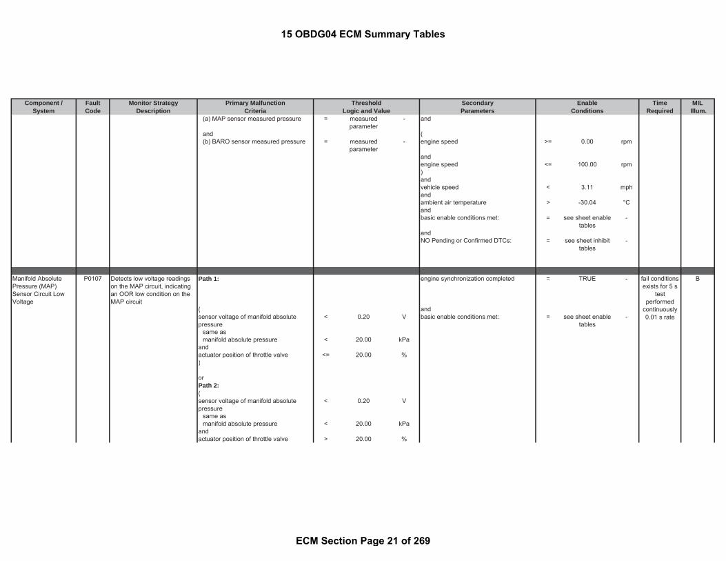
Component / Fault Monitor Strategy Primary Malfunction Secondary Time MILSystem Code Description Criteria Parameters Required Illum.
Threshold EnableLogic and Value Conditions
(a) MAP sensor measured pressure = measuredparameter
- and
and ((b) BARO sensor measured pressure = measured
parameter- engine speed >= 0.00 rpm
andengine speed <= 100.00 rpm)andvehicle speed < 3.11 mphandambient air temperature > -30.04 °Candbasic enable conditions met: = see sheet enable
tables-
andNO Pending or Confirmed DTCs: = see sheet inhibit
tables-
Manifold AbsolutePressure (MAP)Sensor Circuit LowVoltage
P0107 Detects low voltage readingson the MAP circuit, indicatingan OOR low condition on theMAP circuit
Path 1: engine synchronization completed = TRUE - B
( andsensor voltage of manifold absolutepressure
< 0.20 V basic enable conditions met: = see sheet enabletables
-
same asmanifold absolute pressure < 20.00 kPa
andactuator position of throttle valve <= 20.00 %)
orPath 2:(sensor voltage of manifold absolutepressure
< 0.20 V
same asmanifold absolute pressure < 20.00 kPa
andactuator position of throttle valve > 20.00 %
fail conditionsexists for 5 s
testperformed
continuously0.01 s rate
15 OBDG04 ECM Summary Tables
ECM Section Page 21 of 269

Component / Fault Monitor Strategy Primary Malfunction Secondary Time MILSystem Code Description Criteria Parameters Required Illum.
Threshold EnableLogic and Value Conditions
)
Manifold AbsolutePressure (MAP)Sensor Circuit HighVoltage
P0108 Detects high voltage readingson the MAP circuit, indicatingan OOR high condition on theMAP circuit
sensor voltage of manifold absolutepressure
> 4.80 V NO Pending or Confirmed DTCs: = see sheet inhibittables
- B
same as andmanifold absolute pressure > 300.00 kPa engine synchronization completed = TRUE -
andbasic enable conditions met: = see sheet enable
tables-
Intake AirTemperature Sensor 1Circuit Low Bank 1
P0112 Detects low voltage readingson the MAF IAT circuit,indicating an OOR lowcondition on the MAF IATcircuit (IAT #1)
MAF intake air temperature sensorvoltage
< 0.16 V ignition on = TRUE - B
same as andintake air temperature > 129.96 °C basic enable conditions met: = see sheet enable
tables-
Intake AirTemperature Sensor 1Circuit High Bank 1
P0113 Detects high voltage readingson the MAF IAT circuit,indicating an OOR highcondition on the MAF IATcircuit (IAT#1)
MAF intake air temperature sensorvoltage
> 4.80 V ignition on = TRUE - B
same as andintake air temperature < -50.04 °C basic enable conditions met: = see sheet enable
tables-
fail conditionsexists for 5 s
testperformed
continuously0.01 s rate
fail conditionsexists for 5 s
testperformed
continuouslywith 0.1 s rate
fail conditionsexists for 5 s
testperformed
continuouslywith 0.1 s rate
15 OBDG04 ECM Summary Tables
ECM Section Page 22 of 269

Component / Fault Monitor Strategy Primary Malfunction Secondary Time MILSystem Code Description Criteria Parameters Required Illum.
Threshold EnableLogic and Value Conditions
Engine CoolantTemperature (ECT)Sensor Circuit LowVoltage
P0117 Detects low voltage readingson the ECT circuit, indicatingan OOR low condition on theECT circuit
voltage of engine coolant temperaturesensor
< 0.80 V ignition on = TRUE - B
same as andengine coolant temperature > 133 °C basic enable conditions met: = see sheet enable
tables-
Engine CoolantTemperature (ECT)Sensor Circuit HighVoltage
P0118 Detects high voltage readingson the ECT circuit, indicatingan OOR high condition on theECT circuit
voltage of engine coolant temperaturesensor
> 4.75 V ignition on = TRUE - B
same as andengine coolant temperature < -50.04 °C basic enable conditions met: = see sheet enable
tables-
Engine CoolantTemperature / IntakeAir TemperatureCorrelation
P011B Detects a biased ECT or IAT1by comparing start-uptemperatures between the twosensors.
Path 1: minimum engine-off time >= 28800.00 sec B
|(a) - (b)| (see Look-Up-Table #15) > 20 to 999 °C andwhere
( ambient temperature > -60.04 °C(a) captured engine coolanttemperature at start
= measuredparameter
- and
and Engine Running (please see thedefinition)
= TRUE -
(b) captured intake air 1 temperature atstart
= measuredparameter
- for
) time > 0.00 secandengine post drive/ afterun = FALSE
fail conditionsexists for 2.0
stest
performedcontinuously
0.2 s rate
fail conditionsexists for 2.0
stest
performedcontinuously
0.2 s rate
once per drivecycle
15 OBDG04 ECM Summary Tables
ECM Section Page 23 of 269

Component / Fault Monitor Strategy Primary Malfunction Secondary Time MILSystem Code Description Criteria Parameters Required Illum.
Threshold EnableLogic and Value Conditions
anddiagnostic performed in current dc = FALSEandbasic enable conditions met: = see sheet enable
tables-
andNO Pending or Confirmed DTCs: = see sheet inhibit
tables-
Engine CoolantTemperature (ECT)Below ThermostatRegulatingTemperature
P0128 Detects a stuck openthermostat by comparingactual engine coolant heat upprofile to an expected modeledheat up profile.
modeled coolant temperature(model derived from injection quantity,coolant temperature at start, and ambienttemperature)
>= 87.96 °C engine pre drive = FALSE - B
and andmeasured engine coolant temperature < 76.76 °C time since start < 2880.00 sec
andmeasured engine coolant temperature >= -40.04 °Candcaptured value of coolant temperatureduring start
<= 57.96 °C
and(ambient temperature > -7.04 °Candambient temperature < 59.96 °C)andambient temperature (used for highregion determination)
> -30.04 °C
andengine idle time ratio < 0.50 %
which is defined by(idle timedivided bytime since start)
where idle time is incremented when:
fail conditionsexists for 0.2
smonitor runsonce per trip
with 0.2 s ratewhenever
enableconditions are
met
15 OBDG04 ECM Summary Tables
ECM Section Page 24 of 269

Component / Fault Monitor Strategy Primary Malfunction Secondary Time MILSystem Code Description Criteria Parameters Required Illum.
Threshold EnableLogic and Value Conditions
(accelerator pedal value <= 10.00 %andvehicle speed <= 9.94 mphandengine speed <= 1000.00 rpm)
anddiagnostic performed in current dc = FALSE -andbasic enable conditions met: = see sheet enable
tables-
andNO Pending or Confirmed DTCs: = see sheet inhibit
tables-
HO2S Bank 1 Sensor1 circuit low
P0131 Monitoring the A/F sensorcircuits for circuit low failures
AF sensor IP voltage(IP circuit = A/F sensor Input PumpCurrent line which is the measuringcircuit of the O2 concentration)
< 0.90 V Ignition on = TRUE - B
or A/F sensor pumping current controlactive for time (only for VM & UNcircuits)
<= 3.00 sec
A/F sensor -> UN circuit voltage / Vvcc(UN Voltage = A/F sensor nernst cellvoltage)(Vvcc = system supply voltage variesbetween -0.3v to 5.5v)
< 0.35 % of V or
or Activation status of open load test atUN and VM
= TRUE -
A/F sensor -> VM circuit voltage / Vvcc(VM Voltage = reference ground voltage(Vvcc = system supply voltage variesbetween -0.3v to 5.5v)
< 0.40 % of V and
A/F sensor temperature(only for IP circuit))
> 649.96 °C
and
fault exists formore than 2sec; monitorruns at 0.1 swhen enable
conditions aremet
15 OBDG04 ECM Summary Tables
ECM Section Page 25 of 269

Component / Fault Monitor Strategy Primary Malfunction Secondary Time MILSystem Code Description Criteria Parameters Required Illum.
Threshold EnableLogic and Value Conditions
A/F sensor error status bit (seeparameter definition table)
= FALSE -
andA/F sensor heatercontrol reset conditions
= FALSE -
(duty cycle value during sensor heat-up >= 90.25 %
for time >= 19.50 secor
Temperature of A/F sensor (based onsensor internal resistance)
> 804.96 °C
andStatus bit for valid A/F sensor innerResistance (see parameter definitiontable)
= TRUE -
No Pending or Confirmed DTCs: = see sheet inhibittables
-
basic enable conditions met: = see sheet enabletables
-
HO2S Bank 1 Sensor1 circuit high
P0132 Monitoring the A/F sensorcircuits for circuit high failures
AF sensor IP voltage(IP circuit = A/F sensor Input PumpCurrent line which is the measuringcircuit of the O2 concentration)
> 7.50 V Ignition on = TRUE - B
or A/F sensor pumping current controlactive for time (only for VM & UNcircuits)
<= 3.00 sec
A/F sensor -> UN circuit voltage / Vvcc(UN Voltage = A/F sensor nernst cellvoltage)(Vvcc = system supply voltage variesbetween -0.3v to 5.5v)
> 0.80 %V or
or Activation status of open load test atUN and VM
= TRUE -
A/F sensor -> VM circuit voltage / Vvcc(VM Voltage = reference ground voltage(Vvcc = system supply voltage variesbetween -0.3v to 5.5v)
> 0.60 %V and
A/F sensor temperature(only for IP circuit))
> 649.96 °C
fault exists formore than 2sec; monitorruns at 0.1 swhen enable
conditions aremet
15 OBDG04 ECM Summary Tables
ECM Section Page 26 of 269

Component / Fault Monitor Strategy Primary Malfunction Secondary Time MILSystem Code Description Criteria Parameters Required Illum.
Threshold EnableLogic and Value Conditions
andA/F sensor error status bit (seeparameter definition table)
= FALSE -
andA/F sensor heatercontrol reset conditions
= FALSE -
(duty cycle value during sensor heat-up >= 90.25 %
for time >= 19.50 secor
Temperature of A/F sensor (based onsensor internal resistance)
> 804.96 °C
andStatus bit for valid A/F sensor innerResistance (see parameter definitiontable)
= TRUE -
)No Pending or Confirmed DTCs: = see sheet inhibit
tables-
basic enable conditions met: = see sheet enabletables
-
O2 Sensor CircuitSlow Response Bank1 Sensor 1
P0133 Response time of A/F sensorsignal monitoring at transitionfrom load to fuel cut-off mode
Time to reach 30 % of expected rise inO2 concentration
> 3 sec Status: Inactive to Check OpPoint B
OR Influence of InjSys_qTot (Total engineinjection quantity) on lambda signalknown
= TRUE -
Time to reach 60% expected rise from30% expected rise in O2 concentration
> 1.8 sec Status bit which indicates if A/F sensorraw value is valid for A/F sensordiagnostic modules =
TRUE -
OR Test not inhibited through the selectedconditions in the Inhibit ConditionsTable =
TRUE -
Time to reach 60% expected rise in O2concentration
> 4.30 sec basic enable conditions met:=
see sheet enabletables
-
Engine speed > 1100.00 rpmInjection quantity > 20.00 mm^3/r
evBattery voltage > 11.00 VDPF regeneration is not active = TRUE -
fault exists formore than 2fuel cut-off
events;monitor runsat 0.1 s when
enableconditions are
met
15 OBDG04 ECM Summary Tables
ECM Section Page 27 of 269

Component / Fault Monitor Strategy Primary Malfunction Secondary Time MILSystem Code Description Criteria Parameters Required Illum.
Threshold EnableLogic and Value Conditions
Calculated O2 (lambda) signal < 0.10 -A/F sensor error status bit (seeparameter definition table)
= FALSE -
Status: Check OpPoint to Wait forOverrun
Injection quantity deviation < 6.00 mm^3/rev
for time >= 1 secInjection quantity deviation (calculatedfor dynamic response rate monitoring)
> -6.00 mm^3/rev/sec
andInjection quantity deviation (calculatedfor dynamic response rate monitoring)
< 6.00 mm^3/rev/sec
for time > 1.00 secStatus: Wait_for_Overrun to EvaluateEdge
Injection quantity deviation calculatedfor dynamic response rate monitoring
< -4.00 mm^3/rev/sec
Fuel Trim SystemLean
P0171 Monitors the fuel massobserver correction quantity.Detects if the correctionquantity exceeds the feedbacklimit.
Fuel mass observer emission correctionquantity
<= -12.00 mm^3/rev (Status of the Observer function’slambda-signal
= TRUE - B
means(lambda signal from A/F sensor ready(see parameter definition)
= TRUE -
fuel system is in fuel cut off (seeparameter definition)
= FALSE -
Particulate Filter Regeneration Mode = FALSE -((component of combusted fuel in theengine
>= 1 -
orcalculated EGR rate >= 0 -))
for time > 1.00 sec)
fail conditionsexists for 12 smonitor runswith 0.02 s
rate wheneverenable
conditions aremet
15 OBDG04 ECM Summary Tables
ECM Section Page 28 of 269

Component / Fault Monitor Strategy Primary Malfunction Secondary Time MILSystem Code Description Criteria Parameters Required Illum.
Threshold EnableLogic and Value Conditions
ANDController status of the observer = TRUE -
means(Load dependent release state(see Look-Up-Table #40)
= 0 to 1 -
)engine coolant temperature <= 199.96 °Cengine coolant temperature >= 64.96 °CNormal Injection Mode = TRUEBarometric pressure >= 74.80 kPaAmbient temperature >= -7.04 °CNO Pending or Confirmed DTCs: = see sheet inhibit
tables-
basic enable conditions met: = see sheet enabletables
-
Fuel Trim SystemRich
P0172 Monitors the fuel massobserver correction quantity.Detects if the correctionquantity exceeds the feedbacklimit.
Fuel mass observer emission correctionquantity
>= 12.00 mm^3/rev (Status of the Observer function’slambda-signal
= TRUE - B
means(lambda signal from A/F sensor ready(see parameter definition)
= TRUE -
fuel system is in fuel cut off (seeparameter definition)
= FALSE -
Particulate Filter Regeneration Mode = FALSE -((component of combusted fuel in theengine
>= 1 -
orcalculated EGR rate >= 0 -))
for time > 1.00 sec)
ANDController status of the observer = TRUE -
means(
fail conditionsexists for 12 smonitor runswith 0.02 s
rate wheneverenable
conditions aremet
15 OBDG04 ECM Summary Tables
ECM Section Page 29 of 269

Component / Fault Monitor Strategy Primary Malfunction Secondary Time MILSystem Code Description Criteria Parameters Required Illum.
Threshold EnableLogic and Value Conditions
Load dependent release state (see Look-Up-Table #40)
= 0 to 1 -
)engine coolant temperature <= 199.96 °Cengine coolant temperature >= 64.96 °CNormal Injection Mode = TRUEBarometric pressure >= 74.80 kPaAmbient temperature >= -7.04 °CNO Pending or Confirmed DTCs: = see sheet inhibit
tables-
basic enable conditions met: = see sheet enabletables
-
Fuel TemperatureSensor 1 Circuit Low
P0182 Detects low voltage readingsin the fuel pump temperaturesensor 1 circuit, indicating anOOR low condition on the fuelpump temperature sensor 1circuit
voltage of fuel temperature sensor 1 < 1.07 V ignition on = TRUE - B
same as andfuel temperature > 119.96 °C basic enable conditions met: = see sheet enable
tables-
Fuel TemperatureSensor 1 Circuit High
P0183 Detects high voltage readingsin the fuel pump temperaturesensor 1 circuit, indicating anOOR high condition on the fuelpump temperature sensor 1circuit
voltage of fuel temperature sensor 1 > 4.75 V ignition on = TRUE - B
same as andfuel temperature < -50.04 °C basic enable conditions met: = see sheet enable
tables-
fail conditionsexists for 5.0
stest
performedcontinuously
0.2 s rate
fail conditionsexists for 5.0
stest
performedcontinuously
0.2 s rate
15 OBDG04 ECM Summary Tables
ECM Section Page 30 of 269

Component / Fault Monitor Strategy Primary Malfunction Secondary Time MILSystem Code Description Criteria Parameters Required Illum.
Threshold EnableLogic and Value Conditions
Fuel Rail Pressure[FRP] SensorPerformance
P0191 Detects a drifted fuel railpressure sensor bydetermining the adaptationfactor of the fuel rail pressureregulator 2.
fuel pressure regulator 2 adaptationfactor
>= 1.21 factor fuel pressure regulator 2 in closed loopcontrol (please see the definition)
= TRUE - A
or andfuel pressure regulator 2 adaptationfactor
<= 0.79 factor adaptation for fuel pressure regulator 2active
= TRUE -
means(counter for successful adaptation > 0 countsorcounter for the successful calculation ofthe adaptation
> 10.00 counts
and(engine speed > 0.00 rpmandengine speed < 10000.00 rpm)
andvehicle speed <= 203.65 mphand(state machine rail pressure controlequal to pressure control valve
= TRUE -
or(state machine rail pressure controlequal coupled pressure control (railpressure is controlled by metering unitand pressure control valve)
= TRUE -
))
andbasic enable conditions met: = see sheet enable
tables-
fail conditionsexists for 0.01
smonitor runswith 0.01 s
rate wheneverenable
conditions aremet
15 OBDG04 ECM Summary Tables
ECM Section Page 31 of 269

Component / Fault Monitor Strategy Primary Malfunction Secondary Time MILSystem Code Description Criteria Parameters Required Illum.
Threshold EnableLogic and Value Conditions
Detects a biased sensor bydetermining the FRP sensorvoltage to be in the correctrange for atmosphericpressure at engine off and withsufficient pressure bleed-offtime.
rail pressure sensor voltage < 0.42 V (
or engine post drive/ afterun = TRUE -rail pressure sensor voltage > 0.61 V and
fuel temperature > -40.04 °Candengine has already run in this drivingcycle
= TRUE -
andrail pressure is reduced = TRUE -
means commanded rail pressure < 0.00 kPaandfuel pressure regulator 2 current <= 1.70 Amps
andtime since engine off > 15.04 sec
)andnumber of fault measurements duringengine postdrive/ afterun
> 10.00 counts
andbasic enable conditions met: = see sheet enable
tables-
Fuel Rail Pressure[FRP] Sensor CircuitHigh
P0193 Detects high voltage readingson the FRP circuit, indicatingan OOR high condition on theFRP circuit
rail pressure sensor voltage > 4.81 V ignition on = TRUE - A
same as andrail pressure > 220000.00 kPa basic enable conditions met: = see sheet enable
tables-
andNO Pending or Confirmed DTCs: = see sheet inhibit
tables-
fail conditionsexists formore than
0.30 smonitor runs
once perdriving cyclewith 0.01 s
rate wheneverenable
conditions aremet
fail conditionsexists for 0.2
smonitor runswith 0.01 s
rate wheneverenable
conditions aremet
15 OBDG04 ECM Summary Tables
ECM Section Page 32 of 269
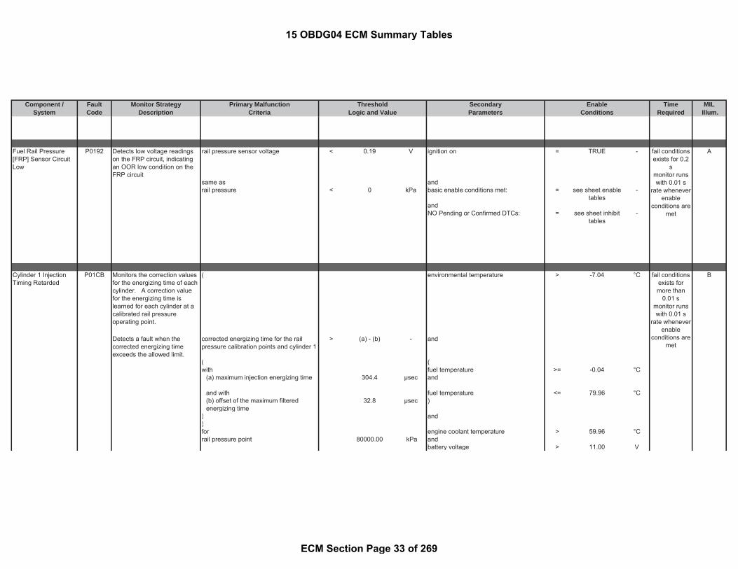
Component / Fault Monitor Strategy Primary Malfunction Secondary Time MILSystem Code Description Criteria Parameters Required Illum.
Threshold EnableLogic and Value Conditions
Fuel Rail Pressure[FRP] Sensor CircuitLow
P0192 Detects low voltage readingson the FRP circuit, indicatingan OOR low condition on theFRP circuit
rail pressure sensor voltage < 0.19 V ignition on = TRUE - A
same as andrail pressure < 0 kPa basic enable conditions met: = see sheet enable
tables-
andNO Pending or Confirmed DTCs: = see sheet inhibit
tables-
Cylinder 1 InjectionTiming Retarded
P01CB Monitors the correction valuesfor the energizing time of eachcylinder. A correction valuefor the energizing time islearned for each cylinder at acalibrated rail pressureoperating point.
( environmental temperature > -7.04 °C B
Detects a fault when thecorrected energizing timeexceeds the allowed limit.
corrected energizing time for the railpressure calibration points and cylinder 1
> (a) - (b) - and
( (with fuel temperature >= -0.04 °C
(a) maximum injection energizing time 304.4 μsec and
and with fuel temperature <= 79.96 °C(b) offset of the maximum filteredenergizing time
32.8 μsec )
) and)for engine coolant temperature > 59.96 °Crail pressure point 80000.00 kPa and
battery voltage > 11.00 V
fail conditionsexists formore than
0.01 smonitor runswith 0.01 s
rate wheneverenable
conditions aremet
fail conditionsexists for 0.2
smonitor runswith 0.01 s
rate wheneverenable
conditions aremet
15 OBDG04 ECM Summary Tables
ECM Section Page 33 of 269

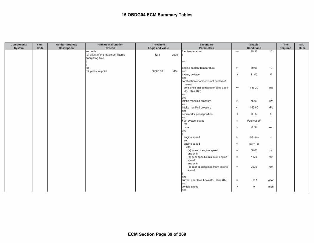
Component / Fault Monitor Strategy Primary Malfunction Secondary Time MILSystem Code Description Criteria Parameters Required Illum.
Threshold EnableLogic and Value Conditions
andcombustion chamber is not cooled off
meanstime since last combustion (see Look-Up-Table #83)
>= 7 to 20 sec
andandintake manifold pressure > 75.00 kPaandintake manifold pressure < 150.00 kPaandaccelerator pedal position < 0.05 %andFuel system status = Fuel cut off -
fortime > 0.00 sec
and(
engine speed > (b) - (a) -andengine speed < (a) + (c) -
with(a) value of engine speed = 30.00 rpmand with(b) gear specific minimum enginespeed
= 1170 rpm
and with(c) gear specific maximum enginespeed
= 2030 rpm
)andcurrent gear (see Look-Up-Table #82) = 0 to 1 gearandvehicle speed > 0 mphandrail pressure deviation from setpointcalculated out of difference betweendesired and actual value
< 2500.00 kPa
for time > 0.20 secandno gear change is occurred = TRUE -and
15 OBDG04 ECM Summary Tables
ECM Section Page 34 of 269

Component / Fault Monitor Strategy Primary Malfunction Secondary Time MILSystem Code Description Criteria Parameters Required Illum.
Threshold EnableLogic and Value Conditions
basic enable conditions met: = see sheet enabletables
-
andNO Pending or Confirmed DTCs: = see sheet enable
tables-
Cylinder 3 InjectionTiming Retarded
P01CF Monitors the correction valuesfor the energizing time of eachcylinder. A correction valuefor the energizing time islearned for each cylinder at acalibrated rail pressureoperating point.
( environmental temperature > -7.04 °C B
Detects a fault when thecorrected energizing timeexceeds the allowed limit.
corrected energizing time for the railpressure calibration points and cylinder 2
> (a) - (b) - and
( (with fuel temperature >= -0.04 °C(a) maximum injection energizing time 304.4 μsec andand with fuel temperature <= 79.96 °C(b) offset of the maximum filteredenergizing time
32.8 μsec )
) and)for engine coolant temperature > 59.96 °Crail pressure point 80000.00 kPa and
battery voltage > 11.00 Vandcombustion chamber is not cooled off
meanstime since last combustion (see Look-Up-Table #83)
>= 7 to 20 sec
andandintake manifold pressure > 75.00 kPaandintake manifold pressure < 150.00 kPaandaccelerator pedal position < 0.05 %and
fail conditionsexists formore than
0.01 smonitor runswith 0.01 s
rate wheneverenable
conditions aremet
15 OBDG04 ECM Summary Tables
ECM Section Page 35 of 269

Component / Fault Monitor Strategy Primary Malfunction Secondary Time MILSystem Code Description Criteria Parameters Required Illum.
Threshold EnableLogic and Value Conditions
Fuel system status = Fuel cut off -fortime > 0.00 sec
and(
engine speed > (b) - (a) -andengine speed < (a) + (c) -
with(a) value of engine speed = 30.00 rpmand with(b) gear specific minimum enginespeed
= 1170 rpm
and with(c) gear specific maximum enginespeed
= 2030 rpm
)andcurrent gear (see Look-Up-Table #82) = 0 to 1 gearandvehicle speed > 0 mphandrail pressure deviation from setpointcalculated out of difference betweendesired and actual value
< 2500.00 kPa
for time > 0.20 secandno gear change is occurred = TRUE -andbasic enable conditions met: = see sheet enable
tables-
andNO Pending or Confirmed DTCs: = see sheet enable
tables-
15 OBDG04 ECM Summary Tables
ECM Section Page 36 of 269

Component / Fault Monitor Strategy Primary Malfunction Secondary Time MILSystem Code Description Criteria Parameters Required Illum.
Threshold EnableLogic and Value Conditions
Cylinder 4 InjectionTiming Retarded
P01D1 Monitors the correction valuesfor the energizing time of eachcylinder. A correction valuefor the energizing time islearned for each cylinder at acalibrated rail pressureoperating point.
( environmental temperature > -7.04 °C B
Detects a fault when thecorrected energizing timeexceeds the allowed limit.
corrected energizing time for the railpressure calibration points and cylinder 3
> (a) - (b) - and
( (with fuel temperature >= -0.04 °C(a) maximum injection energizing time 304.4 μsec andand with fuel temperature <= 79.96 °C(b) offset of the maximum filteredenergizing time
32.8 μsec )
) and)for engine coolant temperature > 59.96 °Crail pressure point 80000.00 kPa and
battery voltage > 11.00 Vandcombustion chamber is not cooled off
meanstime since last combustion (see Look-Up-Table #83)
>= 7 to 20 sec
andandintake manifold pressure > 75.00 kPaandintake manifold pressure < 150.00 kPaandaccelerator pedal position < 0.05 %andFuel system status = Fuel cut off -
fortime > 0.00 sec
and(
engine speed > (b) - (a) -andengine speed < (a) + (c) -
fail conditionsexists formore than
0.01 smonitor runswith 0.01 s
rate wheneverenable
conditions aremet
15 OBDG04 ECM Summary Tables
ECM Section Page 37 of 269

Component / Fault Monitor Strategy Primary Malfunction Secondary Time MILSystem Code Description Criteria Parameters Required Illum.
Threshold EnableLogic and Value Conditions
with(a) value of engine speed = 30.00 rpmand with(b) gear specific minimum enginespeed
= 1170 rpm
and with(c) gear specific maximum enginespeed
= 2030 rpm
)andcurrent gear (see Look-Up-Table #82) = 0 to 1 gearandvehicle speed > 0 mphandrail pressure deviation from setpointcalculated out of difference betweendesired and actual value
< 2500.00 kPa
for time > 0.20 secandno gear change is occurred = TRUE -andbasic enable conditions met: = see sheet enable
tables-
andNO Pending or Confirmed DTCs: = see sheet enable
tables-
Cylinder 2 InjectionTiming Retarded
P01CD Monitors the correction valuesfor the energizing time of eachcylinder. A correction valuefor the energizing time islearned for each cylinder at acalibrated rail pressureoperating point.
( environmental temperature > -7.04 °C B
Detects a fault when thecorrected energizing timeexceeds the allowed limit.
corrected energizing time for the railpressure calibration points and cylinder 4
> (a) - (b) - and
( (with fuel temperature >= -0.04 °C(a) maximum injection energizing time 304.4 μsec and
fail conditionsexists formore than
0.01 smonitor runswith 0.01 s
rate wheneverenable
conditions aremet
15 OBDG04 ECM Summary Tables
ECM Section Page 38 of 269
Component / Fault Monitor Strategy Primary Malfunction Secondary Time MILSystem Code Description Criteria Parameters Required Illum.
Threshold EnableLogic and Value Conditions
and with fuel temperature <= 79.96 °C(b) offset of the maximum filteredenergizing time
32.8 μsec )
) and)for engine coolant temperature > 59.96 °Crail pressure point 80000.00 kPa and
battery voltage > 11.00 Vandcombustion chamber is not cooled off
meanstime since last combustion (see Look-Up-Table #83)
>= 7 to 20 sec
andandintake manifold pressure > 75.00 kPaandintake manifold pressure < 150.00 kPaandaccelerator pedal position < 0.05 %andFuel system status = Fuel cut off -
fortime > 0.00 sec
and(
engine speed > (b) - (a) -andengine speed < (a) + (c) -
with(a) value of engine speed = 30.00 rpmand with(b) gear specific minimum enginespeed
= 1170 rpm
and with(c) gear specific maximum enginespeed
= 2030 rpm
)andcurrent gear (see Look-Up-Table #82) = 0 to 1 gearandvehicle speed > 0 mphand
15 OBDG04 ECM Summary Tables
ECM Section Page 39 of 269

Component / Fault Monitor Strategy Primary Malfunction Secondary Time MILSystem Code Description Criteria Parameters Required Illum.
Threshold EnableLogic and Value Conditions
rail pressure deviation from setpointcalculated out of difference betweendesired and actual value
< 2500.00 kPa
for time > 0.20 secandno gear change is occurred = TRUE -andbasic enable conditions met: = see sheet enable
tables-
andNO Pending or Confirmed DTCs: = see sheet enable
tables-
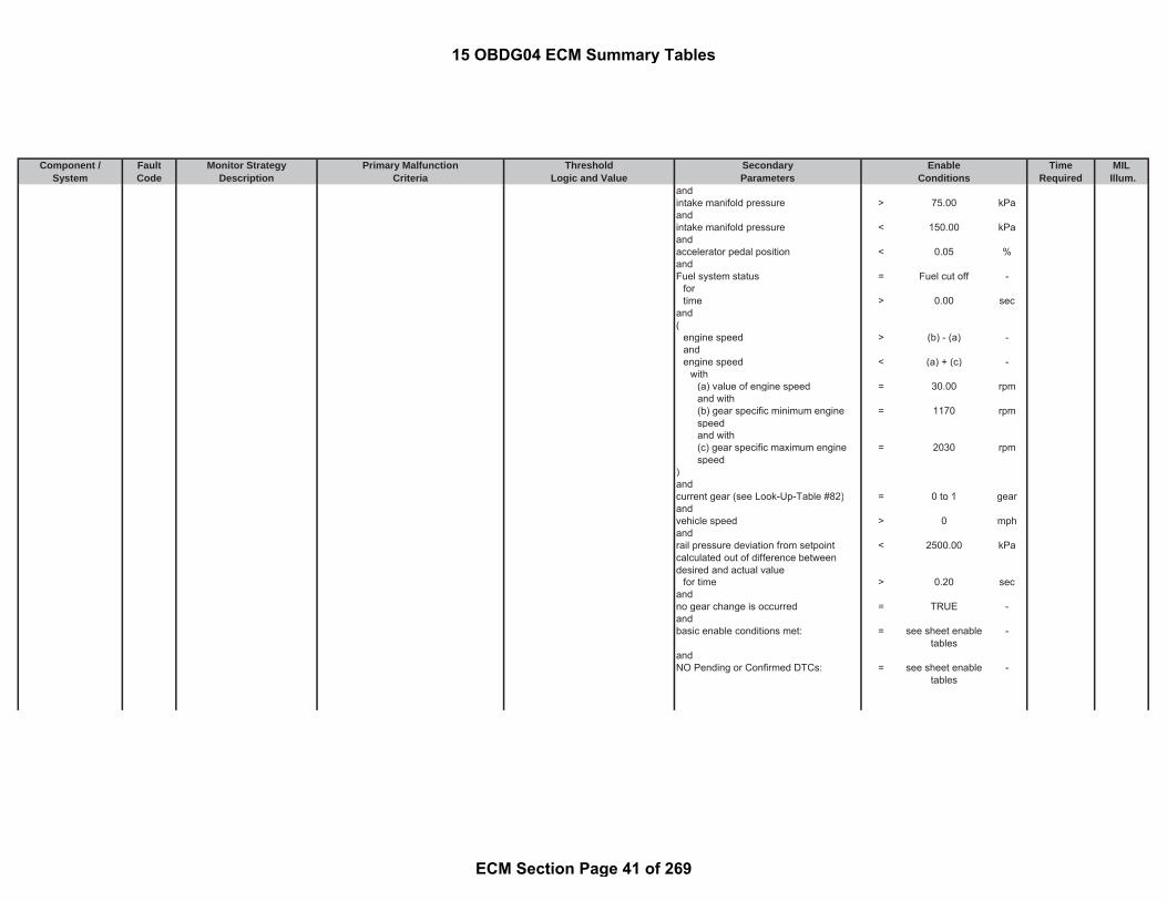
Cylinder 1 InjectionTiming Advanced
P01CC Monitors the correction valuesfor the energizing time of eachcylinder. A correction valuefor the energizing time islearned for each cylinder at acalibrated rail pressureoperating point.
( environmental temperature > -7.04 °C B
Detects a fault when thecorrected energizing time fallsbelow the allowed limit.
corrected energizing time for the railpressure calibration points and cylinder 1
< (a) + (b) - and
( (with fuel temperature >= -0.04 °C(a) minimum injection energizing time 107.2 μsec andand with fuel temperature <= 79.96 °C(b) offset of the minimum filteredenergizing time
47.2 μsec )
) and)for engine coolant temperature > 59.96 °Crail pressure point 80000.00 kPa and
battery voltage > 11.00 Vandcombustion chamber is not cooled off
meanstime since last combustion (see Look-Up-Table #83)
>= 7 to 20 sec
and
fail conditionsexists formore than
0.01 smonitor runswith 0.01 s
rate wheneverenable
conditions aremet
15 OBDG04 ECM Summary Tables
ECM Section Page 40 of 269
Component / Fault Monitor Strategy Primary Malfunction Secondary Time MILSystem Code Description Criteria Parameters Required Illum.
Threshold EnableLogic and Value Conditions
andintake manifold pressure > 75.00 kPaandintake manifold pressure < 150.00 kPaandaccelerator pedal position < 0.05 %andFuel system status = Fuel cut off -
fortime > 0.00 sec
and(
engine speed > (b) - (a) -andengine speed < (a) + (c) -
with(a) value of engine speed = 30.00 rpmand with(b) gear specific minimum enginespeed
= 1170 rpm
and with(c) gear specific maximum enginespeed
= 2030 rpm
)andcurrent gear (see Look-Up-Table #82) = 0 to 1 gearandvehicle speed > 0 mphandrail pressure deviation from setpointcalculated out of difference betweendesired and actual value
< 2500.00 kPa
for time > 0.20 secandno gear change is occurred = TRUE -andbasic enable conditions met: = see sheet enable
tables-
andNO Pending or Confirmed DTCs: = see sheet enable
tables-
15 OBDG04 ECM Summary Tables
ECM Section Page 41 of 269

Component / Fault Monitor Strategy Primary Malfunction Secondary Time MILSystem Code Description Criteria Parameters Required Illum.
Threshold EnableLogic and Value Conditions
Cylinder 3 InjectionTiming Advanced
P01D0 Monitors the correction valuesfor the energizing time of eachcylinder. A correction valuefor the energizing time islearned for each cylinder at acalibrated rail pressureoperating point.
( environmental temperature > -7.04 °C B
Detects a fault when thecorrected energizing time fallsbelow the allowed limit.
corrected energizing time for the railpressure calibration points and cylinder 2
< (a) + (b) - and
( (with fuel temperature >= -0.04 °C(a) minimum injection energizing time 107.2 μsec andand with fuel temperature <= 79.96 °C(b) offset of the minimum filteredenergizing time
47.2 μsec )
) and)for engine coolant temperature > 59.96 °Crail pressure point 80000.00 kPa and
battery voltage > 11.00 Vandcombustion chamber is not cooled off
meanstime since last combustion (see Look-Up-Table #83)
>= 7 to 20 sec
andandintake manifold pressure > 75.00 kPaandintake manifold pressure < 150.00 kPaandaccelerator pedal position < 0.05 %andFuel system status = Fuel cut off -
fortime > 0.00 sec
and(
engine speed > (b) - (a) -and
fail conditionsexists formore than
0.01 smonitor runswith 0.01 s
rate wheneverenable
conditions aremet
15 OBDG04 ECM Summary Tables
ECM Section Page 42 of 269

Component / Fault Monitor Strategy Primary Malfunction Secondary Time MILSystem Code Description Criteria Parameters Required Illum.
Threshold EnableLogic and Value Conditions
engine speed < (a) + (c) -with
(a) value of engine speed = 30.00 rpmand with(b) gear specific minimum enginespeed
= 1170 rpm
and with(c) gear specific maximum enginespeed
= 2030 rpm
)andcurrent gear (see Look-Up-Table #82) = 0 to 1 gearandvehicle speed > 0 mphandrail pressure deviation from setpointcalculated out of difference betweendesired and actual value
< 2500.00 kPa
for time > 0.20 secandno gear change is occurred = TRUE -andbasic enable conditions met: = see sheet enable
tables-
andNO Pending or Confirmed DTCs: = see sheet enable
tables-
Cylinder 4 InjectionTiming Advanced
P01D2 Monitors the correction valuesfor the energizing time of eachcylinder. A correction valuefor the energizing time islearned for each cylinder at acalibrated rail pressureoperating point.
( environmental temperature > -7.04 °C B
Detects a fault when thecorrected energizing time fallsbelow the allowed limit.
corrected energizing time for the railpressure calibration points and cylinder 3
< (a) + (b) - and
( (with fuel temperature >= -0.04 °C
fail conditionsexists formore than
0.01 smonitor runswith 0.01 s
rate wheneverenable
conditions aremet
15 OBDG04 ECM Summary Tables
ECM Section Page 43 of 269

Component / Fault Monitor Strategy Primary Malfunction Secondary Time MILSystem Code Description Criteria Parameters Required Illum.
Threshold EnableLogic and Value Conditions
(a) minimum injection energizing time 107.2 μsec andand with fuel temperature <= 79.96 °C(b) offset of the minimum filteredenergizing time
47.2 μsec )
) and)for engine coolant temperature > 59.96 °Crail pressure point 80000.00 kPa and
battery voltage > 11.00 Vandcombustion chamber is not cooled off
meanstime since last combustion (see Look-Up-Table #83)
>= 7 to 20 sec
andandintake manifold pressure > 75.00 kPaandintake manifold pressure < 150.00 kPaandaccelerator pedal position < 0.05 %andFuel system status = Fuel cut off -
fortime > 0.00 sec
and(
engine speed > (b) - (a) -andengine speed < (a) + (c) -
with(a) value of engine speed = 30.00 rpmand with(b) gear specific minimum enginespeed
= 1170 rpm
and with(c) gear specific maximum enginespeed
= 2030 rpm
)andcurrent gear (see Look-Up-Table #82) = 0 to 1 gearandvehicle speed > 0 mph
15 OBDG04 ECM Summary Tables
ECM Section Page 44 of 269

Component / Fault Monitor Strategy Primary Malfunction Secondary Time MILSystem Code Description Criteria Parameters Required Illum.
Threshold EnableLogic and Value Conditions
andrail pressure deviation from setpointcalculated out of difference betweendesired and actual value
< 2500.00 kPa
for time > 0.20 secandno gear change is occurred = TRUE -andbasic enable conditions met: = see sheet enable
tables-
andNO Pending or Confirmed DTCs: = see sheet enable
tables-
Cylinder 2 InjectionTiming Advanced
P01CE Monitors the correction valuesfor the energizing time of eachcylinder. A correction valuefor the energizing time islearned for each cylinder at acalibrated rail pressureoperating point.
( environmental temperature > -7.04 °C B
Detects a fault when thecorrected energizing time fallsbelow the allowed limit.
corrected energizing time for the railpressure calibration points and cylinder 4
< (a) + (b) - and
( (with fuel temperature >= -0.04 °C(a) minimum injection energizing time 107.2 μsec andand with fuel temperature <= 79.96 °C(b) offset of the minimum filteredenergizing time
47.2 μsec )
) and)for engine coolant temperature > 59.96 °Crail pressure point 80000.00 kPa and
battery voltage > 11.00 Vandcombustion chamber is not cooled off
meanstime since last combustion (see Look-Up-Table #83)
>= 7 to 20 sec
fail conditionsexists formore than
0.01 smonitor runswith 0.01 s
rate wheneverenable
conditions aremet
15 OBDG04 ECM Summary Tables
ECM Section Page 45 of 269

Component / Fault Monitor Strategy Primary Malfunction Secondary Time MILSystem Code Description Criteria Parameters Required Illum.
Threshold EnableLogic and Value Conditions
andandintake manifold pressure > 75.00 kPaandintake manifold pressure < 150.00 kPaandaccelerator pedal position < 0.05 %andFuel system status = Fuel cut off -
fortime > 0.00 sec
and(
engine speed > (b) - (a) -andengine speed < (a) + (c) -
with(a) value of engine speed = 30.00 rpmand with(b) gear specific minimum enginespeed
= 1170 rpm
and with(c) gear specific maximum enginespeed
= 2030 rpm
)andcurrent gear (see Look-Up-Table #82) = 0 to 1 gearandvehicle speed > 0 mphandrail pressure deviation from setpointcalculated out of difference betweendesired and actual value
< 2500.00 kPa
for time > 0.20 secandno gear change is occurred = TRUE -andbasic enable conditions met: = see sheet enable
tables-
andNO Pending or Confirmed DTCs: = see sheet enable
tables-
15 OBDG04 ECM Summary Tables
ECM Section Page 46 of 269

Component / Fault Monitor Strategy Primary Malfunction Secondary Time MILSystem Code Description Criteria Parameters Required Illum.
Threshold EnableLogic and Value Conditions
Coolant TemperatureDropped BelowDiagnostic MonitoringTemperature
P01F0 Detects a stuck openthermostat by monitoring for adecrease of the engine coolanttemperature below the OBDmonitoring threshold duringnormal operating conditions
engine coolant temperature < 69.96 °C engine pre drive = FALSE - B
for fault counter >= 400.00 counts andwhich is equivalent to fault time >= 80.00 sec ambient temperature >= -7.04 °C
andengine coolant temperature at least oncein a drive cycle
>= 69.96 °C
andinstantaneous fuel consumption (low-pass filtered)
>= 2.00 l/h
andbasic enable conditions met: = see sheet enable
tables-
andNO Pending or Confirmed DTCs: = see sheet inhibit
tables-
Injector 1 ControlCircuit
P0201 Diagnoses the Fuel InjectorCylinder #1 low side drivercircuit for circuit faults.
Voltage low during driver off state(indicates open circuit)
= Open Circuit:200 K impedancebetween ECU pinand load
- Engine Running (see parameterdefinition)
= TRUE - Afail conditionsexists formore than
0.04 smonitor runswith 0.01 s
rate wheneverenable
conditions aremet
fail conditionsexists for 0.2
smonitor runs
with 0.2 s ratewhenever
enableconditions are
met
15 OBDG04 ECM Summary Tables
ECM Section Page 47 of 269

Component / Fault Monitor Strategy Primary Malfunction Secondary Time MILSystem Code Description Criteria Parameters Required Illum.
Threshold EnableLogic and Value Conditions
Injector 2 ControlCircuit
P0202 Diagnoses the Fuel InjectorCylinder #4 low side drivercircuit for circuit faults.
Voltage low during driver off state(indicates open circuit)
= Open Circuit:200 K impedancebetween ECU pinand load
- Engine Running (see parameterdefinition)
= TRUE - A
Injector 3 ControlCircuit
P0203 Diagnoses the Fuel InjectorCylinder #2 low side drivercircuit for circuit faults.
Voltage low during driver off state(indicates open circuit)
= Open Circuit:200 K impedancebetween ECU pinand load
- Engine Running (see parameterdefinition)
= TRUE - A
Injector 4 ControlCircuit
P0204 Diagnoses the Fuel InjectorCylinder #3 low side drivercircuit for circuit faults.
Voltage low during driver off state(indicates open circuit)
= Open Circuit:200 K impedancebetween ECU pinand load
- Engine Running (see parameterdefinition)
= TRUE - A
fail conditionsexists formore than
0.04 smonitor runswith 0.01 s
rate wheneverenable
conditions aremet
fail conditionsexists formore than
0.04 smonitor runswith 0.01 s
rate wheneverenable
conditions aremet
fail conditionsexists formore than
0.04 smonitor runswith 0.01 s
rate wheneverenable
conditions aremet
15 OBDG04 ECM Summary Tables
ECM Section Page 48 of 269

Component / Fault Monitor Strategy Primary Malfunction Secondary Time MILSystem Code Description Criteria Parameters Required Illum.
Threshold EnableLogic and Value Conditions
TurbochagerOverboost
P0234 Detects an permanentnegative control deviation ofthe boost pressure
control deviation of the boost pressurecalculated out of difference betweendesired and actual value
< (d) * (e) * (f) - following conditions for time > 0.50 sec B
with ( = FALSE -(d) The lower threshold pressure (seeLook-Up-Table #58)
= -30 to -18 kPa VNT turbo charger offset adaptationactive
= FALSE -
(e) correction factor = 1.00 - and(f) ECB valve based lower limitcorrection factor
= 1.00 - turbo charger (VNT) wiping is active = FALSE -
andabsolute filtered gradient of boostpressure setpoint, PCR_pDesVal ,calculated over a time dT constitutesthe third condition for detecting thesteady state
< 5.00 kPa
andinjection Quantity >= 84.00 mm^3/r
evinjection Quantity <= 160.00 mm^3/r
evandengine Speed >= 2200.00 rpmengine Speed <= 4250.00 rpmandturbocharger control deviation >= -10.00 %turbocharger control deviation <= 10.00 %andcommanded turbocharger position < 100.00 %andparticulate filter regeneration = FALSE -andNO Pending or Confirmed DTCs: see sheet inhibit
tables-
)andbasic enable conditions met: = see sheet enable
tables-
fail conditionsexists for 10 smonitor runswith 0.02 s
rate wheneverenable
conditions aremet
15 OBDG04 ECM Summary Tables
ECM Section Page 49 of 269

Component / Fault Monitor Strategy Primary Malfunction Secondary Time MILSystem Code Description Criteria Parameters Required Illum.
Threshold EnableLogic and Value Conditions
Cylinder 1 BalanceSystem
P0263 Detects if the amount of fuelinjection compensation is atthe control limit as determinedby Fuel Balance Control(FBC)
fuel balance correction quantity < (a) * (b) - fuel balance control in closed loop (seeclosed loop conditions document fordetails)
= TRUE - B
or andfuel balance correction quantity > (c) * (b) - current injection quantity > 6.00 mm^3/r
evwith current injection quantity < 190.00 mm^3/r
ev(a) lower limitation (see Look-Up-Table#37)
= -24 to 0 mm^3/rev engine coolant temperature >= 39.96 °C
ambient pressure >= 0.00 kPaand with engine speed > 575.00 rpm(b) factor for correction quantity = 0.95 factor engine speed < 4000.00 rpmand with vehicle speed <= 186.45 mph(c) upper limitation (see Look-Up-Table#38)
= 0 to 24 mm^3/rev and
basic enable conditions met: = see sheet enabletables
-
andNO Pending or Confirmed DTCs: = see sheet inhibit
tables-
Cylinder 2 BalanceSystem
P0266 Detects if the amount of fuelinjection compensation is atthe control limit as determinedby Fuel Balance Control(FBC)
fuel balance correction quantity < (a) * (b) - fuel balance control in closed loop (seeclosed loop conditions document fordetails)
= TRUE - B
or andfuel balance correction quantity > (c) * (b) - current injection quantity > 6.00 mm^3/r
evwith current injection quantity < 190.00 mm^3/r
ev(a) lower limitation (see Look-Up-Table#37)
= -24 to 0 mm^3/rev engine coolant temperature >= 39.96 °C
ambient pressure >= 0.00 kPaand with engine speed > 575.00 rpm(b) factor for correction quantity = 0.95 factor engine speed < 4000.00 rpmand with vehicle speed <= 186.45 mph
fail conditionsexists for 10 smonitor runswith 0.01 s
rate wheneverenable
conditions aremet
fail conditionsexists for 10 smonitor runswith 0.01 s
rate wheneverenable
conditions aremet
15 OBDG04 ECM Summary Tables
ECM Section Page 50 of 269

Component / Fault Monitor Strategy Primary Malfunction Secondary Time MILSystem Code Description Criteria Parameters Required Illum.
Threshold EnableLogic and Value Conditions
(c) upper limitation (see Look-Up-Table#38)
= 0 to 24 mm^3/rev and
basic enable conditions met: = see sheet enabletables
-
andNO Pending or Confirmed DTCs: = see sheet inhibit
tables-
Cylinder 3 BalanceSystem
P0269 Detects if the amount of fuelinjection compensation is atthe control limit as determinedby Fuel Balance Control(FBC)
fuel balance correction quantity < (a) * (b) - fuel balance control in closed loop (seeclosed loop conditions document fordetails)
= TRUE - B
or andfuel balance correction quantity > (c) * (b) - current injection quantity > 6.00 mm^3/r
evwith current injection quantity < 190.00 mm^3/r
ev(a) lower limitation (see Look-Up-Table#37)
= -24 to 0 mm^3/rev engine coolant temperature >= 39.96 °C
ambient pressure >= 0.00 kPaand with engine speed > 575.00 rpm(b) factor for correction quantity = 0.95 factor engine speed < 4000.00 rpmand with vehicle speed <= 186.45 mph(c) upper limitation (see Look-Up-Table#38)
= 0 to 24 mm^3/rev and
basic enable conditions met: = see sheet enabletables
-
andNO Pending or Confirmed DTCs: = see sheet inhibit
tables-
Cylinder 4 BalanceSystem
P0272 Detects if the amount of fuelinjection compensation is atthe control limit as determinedby Fuel Balance Control(FBC)
fuel balance correction quantity < (a) * (b) - fuel balance control in closed loop (seeclosed loop conditions document fordetails)
= TRUE - B
or and
fail conditionsexists for 10 smonitor runswith 0.01 s
rate wheneverenable
conditions aremet
fail conditionsexists for 10 smonitor runswith 0.01 s
rate wheneverenable
15 OBDG04 ECM Summary Tables
ECM Section Page 51 of 269

Component / Fault Monitor Strategy Primary Malfunction Secondary Time MILSystem Code Description Criteria Parameters Required Illum.
Threshold EnableLogic and Value Conditions
fuel balance correction quantity > (c) * (b) - current injection quantity > 6.00 mm^3/rev
with current injection quantity < 190.00 mm^3/rev
(a) lower limitation (see Look-Up-Table#37)
= -24 to 0 mm^3/rev engine coolant temperature >= 39.96 °C
ambient pressure >= 0.00 kPaand with engine speed > 575.00 rpm(b) factor for correction quantity = 0.95 factor engine speed < 4000.00 rpmand with vehicle speed <= 186.45 mph(c) upper limitation (see Look-Up-Table#38)
= 0 to 24 mm^3/rev and
basic enable conditions met: = see sheet enabletables
-
andNO Pending or Confirmed DTCs: = see sheet inhibit
tables-
CAC Efficiency BelowThreshold
P026A Detects insufficient charge-aircooler efficiency.
The efficiency is calculatedfrom the temperatureupstream of the charge aircooler, temperaturedownstream of the charge aircooler, and modeled ambientair temperature
filtered charge-air cooler efficiency < 0.40 factor vehicle speed >= 31.08 mph B
andair mass flow >= 27.78 g/secair mass flow (see Look-Up-Table #14) <= 55.56 to 277.8 g/sec
andengine coolant temperature >= 69.96 °Cengine coolant temperature <= 125.96 °Candboost pressure ratio(maximum value of (a) and (b) )the maximum value is then divided by (b)
>= 1.22 ratio
with
fail conditionsexists for 90 smonitor runs
once perdriving cycle
with 0.1 s ratewhenever
enableconditions are
met
conditions aremet
15 OBDG04 ECM Summary Tables
ECM Section Page 52 of 269

Component / Fault Monitor Strategy Primary Malfunction Secondary Time MILSystem Code Description Criteria Parameters Required Illum.
Threshold EnableLogic and Value Conditions
(a) boost pressure downstreamcompressor
= calculatedparameter
-
and with(b) ambient pressure = measured
parameter-
andcontrol value of the throttle valve >= -400.00 %control value of the throttle valve <= 5.00 %anddiagnostic performed in current DriveCycle
= FALSE -
and(a) - (b) >= 40.00 °C
with(a) upstream charge air coolertemperature
= measuredparameter
-
and with(b) ambient air temperature = measured
parameter-
andinjection quantity >= 20.00 mm^3/r
evinjection quantity <= 140.00 mm^3/r
evandambient pressure > 74.80 kPaandambient temperature > -7.04 °CandNO Pending or Confirmed DTCs: = see sheet inhibit
tables-
Injection Quantity TooLow
P026C Monitors the fuel massobserver correction quantity.Detects if the correctionquantity exceeds theemissions limit.
Unlimited fuel mass observer correctionquantity - emission control correctionquantity
<= -9.96 mm^3/rev (Status of the Observer function’slambda-signal
= TRUE - B
means(lambda signal from A/F sensor ready(see parameter definition)
= TRUE -
fail conditionsexists for 10 smonitor runswith 0.02 s
rate wheneverenable
conditions aremet
15 OBDG04 ECM Summary Tables
ECM Section Page 53 of 269
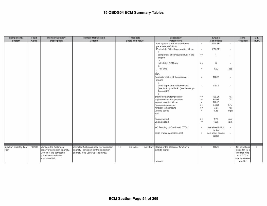
Component / Fault Monitor Strategy Primary Malfunction Secondary Time MILSystem Code Description Criteria Parameters Required Illum.
Threshold EnableLogic and Value Conditions
fuel system is in fuel cut off (seeparameter definition)
= FALSE -
Particulate Filter Regeneration Mode = FALSE -((component of combusted fuel in theengine
>= 1 -
orcalculated EGR rate >= 0 -))
for time > 1.00 sec)
ANDController status of the observer = TRUE -
means(Load dependent release state(see look up table # ) (see Look-Up-Table #40)
= 0 to 1 -
)engine coolant temperature <= 199.96 °Cengine coolant temperature >= 64.96 °CNormal Injection Mode = TRUEBarometric pressure >= 74.80 kPaAmbient temperature >= -7.04 °CVehicle speed < 1.86 mphand(Engine speed >= 575 rpmEngine speed <= 1075 rpm)NO Pending or Confirmed DTCs: = see sheet inhibit
tables-
basic enable conditions met: = see sheet enabletables
-
Injection Quantity TooHigh
P026D Monitors the fuel massobserver correction quantity.Detects if the correctionquantity exceeds theemissions limit.
Unlimited fuel mass observer correctionquantity - emission control correctionquantity (see Look-Up-Table #39)
>= 0.2 to 5.4 mm^3/rev (Status of the Observer function’slambda-signal
= TRUE - B
means
fail conditionsexists for 10 smonitor runswith 0.02 s
rate wheneverenable
15 OBDG04 ECM Summary Tables
ECM Section Page 54 of 269

Component / Fault Monitor Strategy Primary Malfunction Secondary Time MILSystem Code Description Criteria Parameters Required Illum.
Threshold EnableLogic and Value Conditions
(lambda signal from A/F sensor ready(see parameter definition)
= TRUE -
fuel system is in fuel cut off (seeparameter definition)
= FALSE -
Particulate Filter Regeneration Mode = FALSE -((component of combusted fuel in theengine
>= 1 -
orcalculated EGR rate >= 0 -))
for time > 1.00 sec)
ANDController status of the observer = TRUE -
means(Load dependent release state(see look up table # ) (see Look-Up-Table #40)
= 0 to 1 -
)engine coolant temperature <= 199.96 °Cengine coolant temperature >= 64.96 °CNormal Injection Mode = TRUEBarometric pressure >= 74.80 kPaAmbient temperature >= -7.04 °CVehicle speed < 1.86 mphand(Engine speed >= 575 rpmEngine speed <= 1075 rpm)NO Pending or Confirmed DTCs: = see sheet inhibit
tables-
basic enable conditions met: = see sheet enabletables
-
conditions aremet
15 OBDG04 ECM Summary Tables
ECM Section Page 55 of 269

Component / Fault Monitor Strategy Primary Malfunction Secondary Time MILSystem Code Description Criteria Parameters Required Illum.
Threshold EnableLogic and Value Conditions
TurbochagerUnderboost
P0299 Detects an permanent positivecontrol deviation of the boostpressure
control deviation of the boost pressurecalculated out of difference betweendesired and actual value
> (a) * (b) * (c) - following conditions for time > 0.50 sec fail conditionsexists for 7.5
smonitor runswith 0.02 s
rate wheneverenable
conditions aremet
B
with ( = FALSE -(a) the upper limit (see Look-Up-Table#57)
= 33 to 60 kPa VNT turbo charger offset adaptationactive
= FALSE -
(b) Correction factor = 1.00 factor and(c) ECB valve based upper limitcorrection factor
= 1.00 factor turbo charger (VNT) wiping is active = FALSE -
andabsolute filtered gradient of boostpressure setpoint calculated over atime dT constitutes the third conditionfor detecting the steady state
< 7.50 kPa
andinjection Quantity >= 70.00 mm^3/r
evinjection Quantity <= 140.00 mm^3/r
evandengine Speed >= 1750.00 rpmengine Speed <= 3500.00 rpmandparticulate filter regeneration = FALSE -andNO Pending or Confirmed DTCs: = see sheet inhibit
tables-
)andbasic enable conditions met: = see sheet enable
tables-
15 OBDG04 ECM Summary Tables
ECM Section Page 56 of 269

Component / Fault Monitor Strategy Primary Malfunction Secondary Time MILSystem Code Description Criteria Parameters Required Illum.
Threshold EnableLogic and Value Conditions
Cylinder 1 InjectionTiming ReachedFeedback Limit
P02CD Monitors the correction valuesfor the energizing time of eachcylinder.A correction value for theenergizing time is learned foreach cylinder at three differentrail pressure operating point.
( environmental temperature > -7.04 °C B
Detects a fault when thecorrected energizing timeexceeds the feedback controllimit.
corrected energizing time for the railpressure calibration points and cylinder 1
> (a) - (b) - and
( (with fuel temperature >= -0.04 °C
(a) maximum injection energizing time(see Look-Up-Table #20)
0 to 547.2 μsec and
and with fuel temperature <= 79.96 °C(b) offset of the maximum filteredenergizing time (see Look-Up-Table#22)
0 to 16 μsec )
) and)OR engine coolant temperature > 59.96 °C( andcorrected energizing time for the railpressure calibration points and cylinder 1
< (a) + (b) - battery voltage > 11.00 V
( andwith combustion chamber is not cooled off
(a) minimum injection energizing time(see Look-Up-Table #21)
0 to 137.2 μsec means
and with time since last combustion (see Look-Up-Table #83)
>= 7 to 20 sec
(b) offset of the minimum filteredenergizing time (see Look-Up-Table#23)
0 to 16 μsec and
) and) intake manifold pressure > 75.00 kPafor andrail pressure point (see Look-Up-Table#19)
0 to 80000 kPa intake manifold pressure < 150.00 kPa
andaccelerator pedal position < 0.05 %
fail conditionsexists for
more than 0.5s
monitor runswith 0.01 s
rate wheneverenable
conditions aremet
15 OBDG04 ECM Summary Tables
ECM Section Page 57 of 269

Component / Fault Monitor Strategy Primary Malfunction Secondary Time MILSystem Code Description Criteria Parameters Required Illum.
Threshold EnableLogic and Value Conditions
andFuel system status = Fuel cut off -
fortime > 0.00 sec
and(
engine speed > (b) - (a) -andengine speed < (a) + (c) -
with(a) value of engine speed = 30.00 rpmand with(b) gear specific minimum enginespeed
= 1170 rpm
and with(c) gear specific maximum enginespeed
= 2030 rpm
)andcurrent gear (see Look-Up-Table #82) = 0 to 1 gearandvehicle speed > 0 mphandrail pressure deviation from setpointcalculated out of difference betweendesired and actual value
< 2500.00 kPa
for time > 0.20 secandno gear change is occurred = TRUE -andbasic enable conditions met: = see sheet enable
tables-
andNO Pending or Confirmed DTCs: = see sheet enable
tables-
15 OBDG04 ECM Summary Tables
ECM Section Page 58 of 269

Component / Fault Monitor Strategy Primary Malfunction Secondary Time MILSystem Code Description Criteria Parameters Required Illum.
Threshold EnableLogic and Value Conditions
Cylinder 2 InjectionTiming ReachedFeedback Limit
P02CF Monitors the correction valuesfor the energizing time of eachcylinder.A correction value for theenergizing time is learned foreach cylinder at three differentrail pressure operating point.
( environmental temperature > -7.04 °C B
Detects a fault when thecorrected energizing timeexceeds the feedback controllimit.
corrected energizing time for the railpressure calibration points and cylinder 1
> (a) - (b) - and
( (with fuel temperature >= -0.04 °C
(a) maximum injection energizing time(see Look-Up-Table #20)
0 to 547.2 μsec and
and with fuel temperature <= 79.96 °C(b) offset of the maximum filteredenergizing time (see Look-Up-Table#22)
0 to 16 μsec )
) and)OR engine coolant temperature > 59.96 °C( andcorrected energizing time for the railpressure calibration points and cylinder 1
< (a) + (b) - battery voltage > 11.00 V
( andwith combustion chamber is not cooled off
(a) minimum injection energizing time(see Look-Up-Table #21)
0 to 137.2 μsec means
and with time since last combustion (see Look-Up-Table #83)
>= 7 to 20 sec
(b) offset of the minimum filteredenergizing time (see Look-Up-Table#23)
0 to 16 μsec and
) and) intake manifold pressure > 75.00 kPafor andrail pressure point (see Look-Up-Table#19)
0 to 80000 kPa intake manifold pressure < 150.00 kPa
andaccelerator pedal position < 0.05 %
fail conditionsexists for
more than 0.5s
monitor runswith 0.01 s
rate wheneverenable
conditions aremet
15 OBDG04 ECM Summary Tables
ECM Section Page 59 of 269
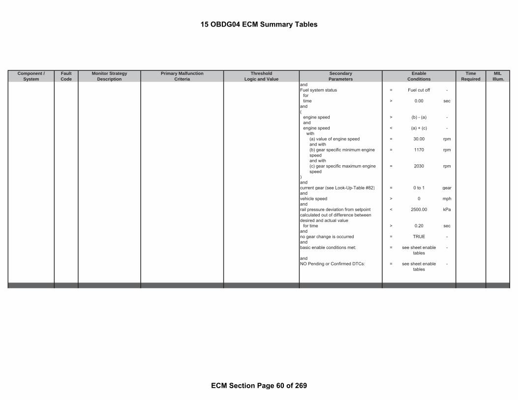
Component / Fault Monitor Strategy Primary Malfunction Secondary Time MILSystem Code Description Criteria Parameters Required Illum.
Threshold EnableLogic and Value Conditions
andFuel system status = Fuel cut off -
fortime > 0.00 sec
and(
engine speed > (b) - (a) -andengine speed < (a) + (c) -
with(a) value of engine speed = 30.00 rpmand with(b) gear specific minimum enginespeed
= 1170 rpm
and with(c) gear specific maximum enginespeed
= 2030 rpm
)andcurrent gear (see Look-Up-Table #82) = 0 to 1 gearandvehicle speed > 0 mphandrail pressure deviation from setpointcalculated out of difference betweendesired and actual value
< 2500.00 kPa
for time > 0.20 secandno gear change is occurred = TRUE -andbasic enable conditions met: = see sheet enable
tables-
andNO Pending or Confirmed DTCs: = see sheet enable
tables-
15 OBDG04 ECM Summary Tables
ECM Section Page 60 of 269

Component / Fault Monitor Strategy Primary Malfunction Secondary Time MILSystem Code Description Criteria Parameters Required Illum.
Threshold EnableLogic and Value Conditions
Cylinder 3 InjectionTiming ReachedFeedback Limit
P02D1 Monitors the correction valuesfor the energizing time of eachcylinder.A correction value for theenergizing time is learned foreach cylinder at three differentrail pressure operating point.
( environmental temperature > -7.04 °C B
Detects a fault when thecorrected energizing timeexceeds the feedback controllimit.
corrected energizing time for the railpressure calibration points and cylinder 1
> (a) - (b) - and
( (with fuel temperature >= -0.04 °C
(a) maximum injection energizing time(see Look-Up-Table #20)
0 to 547.2 μsec and
and with fuel temperature <= 79.96 °C(b) offset of the maximum filteredenergizing time (see Look-Up-Table#22)
0 to 16 μsec )
) and)OR engine coolant temperature > 59.96 °C( andcorrected energizing time for the railpressure calibration points and cylinder 1
< (a) + (b) - battery voltage > 11.00 V
( andwith combustion chamber is not cooled off
(a) minimum injection energizing time(see Look-Up-Table #21)
0 to 137.2 μsec means
and with time since last combustion (see Look-Up-Table #83)
>= 7 to 20 sec
(b) offset of the minimum filteredenergizing time (see Look-Up-Table#23)
0 to 16 μsec and
) and) intake manifold pressure > 75.00 kPafor andrail pressure point (see Look-Up-Table#19)
0 to 80000 kPa intake manifold pressure < 150.00 kPa
andaccelerator pedal position < 0.05 %
fail conditionsexists for
more than 0.5s
monitor runswith 0.01 s
rate wheneverenable
conditions aremet
15 OBDG04 ECM Summary Tables
ECM Section Page 61 of 269

Component / Fault Monitor Strategy Primary Malfunction Secondary Time MILSystem Code Description Criteria Parameters Required Illum.
Threshold EnableLogic and Value Conditions
andFuel system status = Fuel cut off -
fortime > 0.00 sec
and(
engine speed > (b) - (a) -andengine speed < (a) + (c) -
with(a) value of engine speed = 30.00 rpmand with(b) gear specific minimum enginespeed
= 1170 rpm
and with(c) gear specific maximum enginespeed
= 2030 rpm
)andcurrent gear (see Look-Up-Table #82) = 0 to 1 gearandvehicle speed > 0 mphandrail pressure deviation from setpointcalculated out of difference betweendesired and actual value
< 2500.00 kPa
for time > 0.20 secandno gear change is occurred = TRUE -andbasic enable conditions met: = see sheet enable
tables-
andNO Pending or Confirmed DTCs: = see sheet enable
tables-
15 OBDG04 ECM Summary Tables
ECM Section Page 62 of 269

Component / Fault Monitor Strategy Primary Malfunction Secondary Time MILSystem Code Description Criteria Parameters Required Illum.
Threshold EnableLogic and Value Conditions
Cylinder 4 InjectionTiming ReachedFeedback Limit
P02D3 Monitors the correction valuesfor the energizing time of eachcylinder.A correction value for theenergizing time is learned foreach cylinder at three differentrail pressure operating point.
( environmental temperature > -7.04 °C B
Detects a fault when thecorrected energizing timeexceeds the feedback controllimit.
corrected energizing time for the railpressure calibration points and cylinder 1
> (a) - (b) - and
( (with fuel temperature >= -0.04 °C
(a) maximum injection energizing time(see Look-Up-Table #20)
0 to 547.2 μsec and
and with fuel temperature <= 79.96 °C(b) offset of the maximum filteredenergizing time (see Look-Up-Table#22)
0 to 16 μsec )
) and)OR engine coolant temperature > 59.96 °C( andcorrected energizing time for the railpressure calibration points and cylinder 1
< (a) + (b) - battery voltage > 11.00 V
( andwith combustion chamber is not cooled off
(a) minimum injection energizing time(see Look-Up-Table #21)
0 to 137.2 μsec means
and with time since last combustion (see Look-Up-Table #83)
>= 7 to 20 sec
(b) offset of the minimum filteredenergizing time (see Look-Up-Table#23)
0 to 16 μsec and
) and) intake manifold pressure > 75.00 kPafor andrail pressure point (see Look-Up-Table#19)
0 to 80000 kPa intake manifold pressure < 150.00 kPa
andaccelerator pedal position < 0.05 %
fail conditionsexists for
more than 0.5s
monitor runswith 0.01 s
rate wheneverenable
conditions aremet
15 OBDG04 ECM Summary Tables
ECM Section Page 63 of 269

Component / Fault Monitor Strategy Primary Malfunction Secondary Time MILSystem Code Description Criteria Parameters Required Illum.
Threshold EnableLogic and Value Conditions
andFuel system status = Fuel cut off -
fortime > 0.00 sec
and(
engine speed > (b) - (a) -andengine speed < (a) + (c) -
with(a) value of engine speed = 30.00 rpmand with(b) gear specific minimum enginespeed
= 1170 rpm
and with(c) gear specific maximum enginespeed
= 2030 rpm
)andcurrent gear (see Look-Up-Table #82) = 0 to 1 gearandvehicle speed > 0 mphandrail pressure deviation from setpointcalculated out of difference betweendesired and actual value
< 2500.00 kPa
for time > 0.20 secandno gear change is occurred = TRUE -andbasic enable conditions met: = see sheet enable
tables-
andNO Pending or Confirmed DTCs: = see sheet enable
tables-
Intake Air Flow ValveControl Circuit
P02E0 Diagnoses the Throttle Valvelow side driver circuit for circuitfaults.
Voltage low during driver off state(indicates open circuit)
= Open Circuit:200 K impedancebetween ECU pinand load
- battery voltage > 11.00 V Bfail conditionsexists for
1,1smonitor runswith 0.005 st h
15 OBDG04 ECM Summary Tables
ECM Section Page 64 of 269

Component / Fault Monitor Strategy Primary Malfunction Secondary Time MILSystem Code Description Criteria Parameters Required Illum.
Threshold EnableLogic and Value Conditions
fortime > 3.00 sec
andstarter is active cranking = FALSE -
fortime > 3.00 sec
andbasic enable conditions met: = see sheet enable
tables-
andThrottle Valve Actuator Solenoid ControlCircuit
= ACTIVE -
andNO Pending or Confirmed DTCs = see sheet inhibit
tables-
The ECM detects that the commandedstate of the driver and the actual state ofthe control circuit do not match.
battery voltage > 11.00 V
fortime > 3.00 sec
andstarter is active cranking = FALSE -
fortime > 3.00 sec
andbasic enable conditions met: = see sheet enable
tables-
andThrottle Valve Actuator Solenoid ControlCircuit
= ACTIVE -
andOpen Load Diagnosis active = FALSE -NO Pending or Confirmed DTCs = see sheet inhibit
tables-
The ECM detects that the commandedstate of the driver and the actual state ofthe control circuit do not match.
battery voltage > 11.00 V fail conditionsexists for 0,5
s
rate wheneverenable
conditions aremet
fail conditionsexists for 0,5
smonitor runswith 0.005 s
rate wheneverenable
conditions aremet
15 OBDG04 ECM Summary Tables
ECM Section Page 65 of 269

Component / Fault Monitor Strategy Primary Malfunction Secondary Time MILSystem Code Description Criteria Parameters Required Illum.
Threshold EnableLogic and Value Conditions
fortime > 3.00 sec
andstarter is active cranking = FALSE -
fortime > 3.00 sec
andbasic enable conditions met: = see sheet enable
tables-
andThrottle Valve Actuator Solenoid ControlCircuit
= ACTIVE -
andOpen Load Diagnosis active = FALSE -NO Pending or Confirmed DTCs = see sheet inhibit
tables-
Intake Air Flow ValveControl Circuit 1 LowVoltage
P02E2 Diagnoses the Throttle Valvelow side driver circuit for circuitfaults.
Voltage low during driver off state(indicates short-to-ground)
= Short to ground: 0.5
impedancebetween signaland controllerground
- battery voltage > 11.00 V B
fortime > 3.00 sec
andstarter is active cranking = FALSE -
fortime > 3.00 sec
andbasic enable conditions met: = see sheet enable
tables-
andThrottle Valve Actuator Solenoid ControlCircuit
= ACTIVE -
andOpen Load Diagnosis active = FALSE -NO Pending or Confirmed DTCs = see sheet inhibit
tables-
monitor runswith 0.005 s
rate wheneverenable
conditions aremet
fail conditionsexists for 0,5
smonitor runswith 0.005 s
rate wheneverenable
conditions aremet
15 OBDG04 ECM Summary Tables
ECM Section Page 66 of 269

Component / Fault Monitor Strategy Primary Malfunction Secondary Time MILSystem Code Description Criteria Parameters Required Illum.
Threshold EnableLogic and Value Conditions
Intake Air Flow ValveControl Circuit 1 HighVoltage
P02E3 Diagnoses the Throttle Valvelow side driver circuit for circuitfaults.
Voltage high during driver on state(indicates short to power)
= Short to power: ≤ 0.5 Ωimpedancebetween signaland controllerpower
- battery voltage > 11.00 V B
fortime > 3.00 sec
andstarter is active cranking = FALSE -
fortime > 3.00 sec
andbasic enable conditions met: = see sheet enable
tables-
andThrottle Valve Actuator Solenoid ControlCircuit
= ACTIVE -
andOpen Load Diagnosis active = FALSE -NO Pending or Confirmed DTCs = see sheet inhibit
tables-
Throttle ValveActuator (TVA)Position SensorPerformance
P02E7 Detects in range TVA positionerrors by comparing thedifference between desiredand actual TVA position.
throttle valve control deviation calculatedout of difference between desired andactual value
< 10.00 % throttle valve controller bypass is active = FALSE - B
or andthrottle valve control deviation calculatedout of difference between desired andactual value
> -10.00 % throttle valve is driven to a mechanicalstop
= FALSE -
andThrottle Governor is active = TRUE -andThrottle Valve Permanent ControlDeviation
= FALSE -
and
fail conditionsexists for 0,5
smonitor runswith 0.005 s
rate wheneverenable
conditions aremet
fail conditionsexists for 10 smonitor runswith 0.005 s
rate wheneverenable
conditions aremet
15 OBDG04 ECM Summary Tables
ECM Section Page 67 of 269

Component / Fault Monitor Strategy Primary Malfunction Secondary Time MILSystem Code Description Criteria Parameters Required Illum.
Threshold EnableLogic and Value Conditions
throttle valve is detected as frozen = TRUE -means
Engine Coolant Temperature < 198.96 °Candengine speed (see Look-Up-Table #81) > 850 to 1100 rpm
and(Offset learning done on previous drivingcycle
= TRUE -
OROffset learning on going = TRUE -)andbasic enable conditions met = see sheet enable
tables-
andNO Pending or Confirmed DTCs: = see sheet inhibit
tables-
Diesel Intake Air FlowPosition SensorCircuit Low Voltage
P02E8 Detects low voltage readingson the throttle valve positionsensor circuit, indicating anOOR low condition on thethrottle valve position sensorcircuit
measured throttle valve position voltage < 0.41 V ignition on = TRUE - A
same as andthrottle position < -10 % basic enable conditions met = see sheet enable
tables-
andNo Pending or Confirmed DTCs: = see sheet inhibit
tables-
Diesel Intake Air FlowPosition SensorCircuit High Voltage
P02E9 Detects high voltage readingson the throttle valve positionsensor circuit, indicating anOOR high condition on thethrottle valve position sensorcircuit
measured throttle valve position voltage > 4.61 V ignition on = TRUE - A
fail conditionsexists for 5.0
s; testperformed
continuously0.005 s rate
fail conditionsexists for 5.0
s; testperformed
continuously0.005 s rate
15 OBDG04 ECM Summary Tables
ECM Section Page 68 of 269

Component / Fault Monitor Strategy Primary Malfunction Secondary Time MILSystem Code Description Criteria Parameters Required Illum.
Threshold EnableLogic and Value Conditions
same as andthrottle position > 105 % basic enable conditions met = see sheet enable
tables-
andNo Pending or Confirmed DTCs: = see sheet inhibit
tables-
Intake Air Flow ValveControl Motor CurrentPerformance
P02EB Electronic out-put drivercircuitry determines circuitintegrity on the intake air flowvalve.
The ECM detects that the commandedstate of the driver and the actual state ofthe control circuit do not match.
battery voltage > 11.00 V B
fortime > 3.00 sec
andstarter is active cranking = FALSE -
fortime > 3.00 sec
andbasic enable conditions met: = see sheet enable
tables-
andThrottle Valve Actuator Solenoid ControlCircuit
= ACTIVE -
andOpen Load Diagnosis active = FALSE -NO Pending or Confirmed DTCs = see sheet inhibit
tables-
Engine MisfireDetected
P0300 Indicates that the engine hasexperienced more than onecylinder misfiring, detected bya crankshaft angle delay thatis too great, caused by a dropin the engine speed
angular acceleration of the crankshaft(see Look-Up-Table #52)
< -5.75 to -2.52 sec^(2) ( B
and Engine Running (see parameterdefinition)
= TRUE -
number of detected misfires >= 200.00 counts andfor engine speed > 350.00 rpm
fail conditionsexists for 2.0
smonitor runswith 0.005 s
rate wheneverenable
conditions aremet
fail conditionsexists for 0.02
smonitor runswith 0.02 s
rate wheneverenable
conditions aremet
15 OBDG04 ECM Summary Tables
ECM Section Page 69 of 269

Component / Fault Monitor Strategy Primary Malfunction Secondary Time MILSystem Code Description Criteria Parameters Required Illum.
Threshold EnableLogic and Value Conditions
evaluated crankshaft revolutions >= (a) * (b) - andwith engine speed < 1400.00 rpm
(a) number of crankshaft revolutionsper block
= 20.00 counts )
and with and(b) number of test blocks = 45.00 counts |(a) - (b)| < 450.00 rpm
and withmisfires exist on more than one cylinder = TRUE - (a) actual desired idle speed = calculated
parameter-
and with(b) engine speed = measured
parameter-
and(current injection quantity > 4.00 mm^3/r
evandcurrent injection quantity < 180.00 mm^3/r
ev)andengine coolant temperature >= 40.06 °Candvehicle speed <= 1.86 mphandtime since start >= 10.00 secanddeletion of error memory (Mode$4) notexecuted since last check of themonitoring conditions
= TRUE -
andadaptation value for tooth wheel hasbeen learned
= TRUE -
andcurrent change in engine speed <= 450.00 rpmfortime = 0.00 secandcurrent change in injection quantity <= 170.00 mm^3/r
evfor
15 OBDG04 ECM Summary Tables
ECM Section Page 70 of 269

Component / Fault Monitor Strategy Primary Malfunction Secondary Time MILSystem Code Description Criteria Parameters Required Illum.
Threshold EnableLogic and Value Conditions
time = 0.00 secandbasic enable conditions met: = see sheet enable
tables-
andNO Pending or Confirmed DTCs: = see sheet inhibit
tables-
Cylinder 1 MisfireDetected
P0301 Indicates that the engine hasexperienced a single cylindermisfiring, detected by acrankshaft angle delay that istoo great, caused by a drop inthe engine speed
angular acceleration of the crankshaft(see Look-Up-Table #52)
< -5.75 to -2.52 sec^(2) ( B
and Engine Running (see parameterdefinition)
= TRUE -
number of detected misfires >= 200.00 counts andfor engine speed > 350.00 rpmevaluated crankshaft revolutions >= (a) * (b) - andwith engine speed < 1400.00 rpm
(a) number of crankshaft revolutionsper block
= 20.00 counts )
and with and(b) number of test blocks = 45.00 counts |(a) - (b)| < 450.00 rpm
with(a) actual desired idle speed = calculated
parameter-
and with(b) engine speed = measured
parameter-
and(current injection quantity > 4.00 mm^3/r
evandcurrent injection quantity < 180.00 mm^3/r
ev)andengine coolant temperature >= 40.06 °Cand
fail conditionsexists for 0.02s monitor runs
with 0.02 srate whenever
enableconditions are
met
15 OBDG04 ECM Summary Tables
ECM Section Page 71 of 269

Component / Fault Monitor Strategy Primary Malfunction Secondary Time MILSystem Code Description Criteria Parameters Required Illum.
Threshold EnableLogic and Value Conditions
vehicle speed <= 1.86 mphandtime since start >= 10.00 secanddeletion of error memory (Mode$4) notexecuted since last check of themonitoring conditions
= TRUE -
andadaptation value for tooth wheel hasbeen learned
= TRUE -
andcurrent change in engine speed <= 450.00 rpmfortime = 0.00 secandcurrent change in injection quantity <= 170.00 mm^3/r
evfortime = 0.00 secandbasic enable conditions met: = see sheet enable
tables-
andNO Pending or Confirmed DTCs: = see sheet inhibit
tables-
Cylinder 3 MisfireDetected
P0303 Indicates that the engine hasexperienced a single cylindermisfiring, detected by acrankshaft angle delay that istoo great, caused by a drop inthe engine speed
angular acceleration of the crankshaft(see Look-Up-Table #52)
< -5.75 to -2.52 sec^(2) ( B
and Engine Running (see parameterdefinition)
= TRUE -
number of detected misfires >= 200.00 counts andfor engine speed > 350.00 rpmevaluated crankshaft revolutions >= (a) * (b) - andwith engine speed < 1400.00 rpm
fail conditionsexists for 0.02
smonitor runswith 0.02 s
rate wheneverenable
conditions aremet
15 OBDG04 ECM Summary Tables
ECM Section Page 72 of 269

Component / Fault Monitor Strategy Primary Malfunction Secondary Time MILSystem Code Description Criteria Parameters Required Illum.
Threshold EnableLogic and Value Conditions
(a) number of crankshaft revolutionsper block
= 20.00 counts )
and with and(b) number of test blocks = 45.00 counts |(a) - (b)| < 450.00 rpm
with(a) actual desired idle speed = calculated
parameter-
and with(b) engine speed = measured
parameter-
and(current injection quantity > 4.00 mm^3/r
evandcurrent injection quantity < 180.00 mm^3/r
ev)andengine coolant temperature >= 40.06 °Candvehicle speed <= 1.86 mphandtime since start >= 10.00 secanddeletion of error memory (Mode$4) notexecuted since last check of themonitoring conditions
= TRUE -
andadaptation value for tooth wheel hasbeen learned
= TRUE -
andcurrent change in engine speed <= 450.00 rpmfortime = 0.00 secandcurrent change in injection quantity <= 170.00 mm^3/r
evfortime = 0.00 secand
15 OBDG04 ECM Summary Tables
ECM Section Page 73 of 269

Component / Fault Monitor Strategy Primary Malfunction Secondary Time MILSystem Code Description Criteria Parameters Required Illum.
Threshold EnableLogic and Value Conditions
basic enable conditions met: = see sheet enabletables
-
andNO Pending or Confirmed DTCs: = see sheet inhibit
tables-
Cylinder 4 MisfireDetected
P0304 Indicates that the engine hasexperienced a single cylindermisfiring, detected by acrankshaft angle delay that istoo great, caused by a drop inthe engine speed
angular acceleration of the crankshaft(see Look-Up-Table #52)
< -5.75 to -2.52 sec^(2) ( B
and Engine Running (see parameterdefinition)
= TRUE -
number of detected misfires >= 200.00 counts andfor engine speed > 350.00 rpmevaluated crankshaft revolutions >= (a) * (b) - andwith engine speed < 1400.00 rpm
(a) number of crankshaft revolutionsper block
= 20.00 counts )
and with and(b) number of test blocks = 45.00 counts |(a) - (b)| < 450.00 rpm
with(a) actual desired idle speed = calculated
parameter-
and with(b) engine speed = measured
parameter-
and(current injection quantity > 4.00 mm^3/r
evandcurrent injection quantity < 180.00 mm^3/r
ev)andengine coolant temperature >= 40.06 °Candvehicle speed <= 1.86 mphand
fail conditionsexists for 0.02
smonitor runswith 0.02 s
rate wheneverenable
conditions aremet
15 OBDG04 ECM Summary Tables
ECM Section Page 74 of 269

Component / Fault Monitor Strategy Primary Malfunction Secondary Time MILSystem Code Description Criteria Parameters Required Illum.
Threshold EnableLogic and Value Conditions
time since start >= 10.00 secanddeletion of error memory (Mode$4) notexecuted since last check of themonitoring conditions
= TRUE -
andadaptation value for tooth wheel hasbeen learned
= TRUE -
andcurrent change in engine speed <= 450.00 rpmfortime = 0.00 secandcurrent change in injection quantity <= 170.00 mm^3/r
evfortime = 0.00 secandbasic enable conditions met: = see sheet enable
tables-
andNO Pending or Confirmed DTCs: = see sheet inhibit
tables-
Cylinder 2 MisfireDetected
P0302 Indicates that the engine hasexperienced a single cylindermisfiring, detected by acrankshaft angle delay that istoo great, caused by a drop inthe engine speed
angular acceleration of the crankshaft(see Look-Up-Table #52)
< -5.75 to -2.52 sec^(2) ( B
and Engine Running (see parameterdefinition)
= TRUE -
number of detected misfires >= 200.00 counts andfor engine speed > 350.00 rpmevaluated crankshaft revolutions >= (a) * (b) - andwith engine speed < 1400.00 rpm
(a) number of crankshaft revolutionsper block
= 20.00 counts )
and with and
fail conditionsexists for 0.02
msmonitor runswith 0.02 s
rate wheneverenable
conditions aremet
15 OBDG04 ECM Summary Tables
ECM Section Page 75 of 269

Component / Fault Monitor Strategy Primary Malfunction Secondary Time MILSystem Code Description Criteria Parameters Required Illum.
Threshold EnableLogic and Value Conditions
(b) number of test blocks = 45.00 counts |(a) - (b)| < 450.00 rpmwith
(a) actual desired idle speed = calculatedparameter
-
and with(b) engine speed = measured
parameter-
and(current injection quantity > 4.00 mm^3/r
evandcurrent injection quantity < 180.00 mm^3/r
ev)andengine coolant temperature >= 40.06 °Candvehicle speed <= 1.86 mphandtime since start >= 10.00 secanddeletion of error memory (Mode$4) notexecuted since last check of themonitoring conditions
= TRUE -
andadaptation value for tooth wheel hasbeen learned
= TRUE -
andcurrent change in engine speed <= 450.00 rpmfortime = 0.00 secandcurrent change in injection quantity <= 170.00 mm^3/r
evfortime = 0.00 secandbasic enable conditions met: = see sheet enable
tables-
and
15 OBDG04 ECM Summary Tables
ECM Section Page 76 of 269
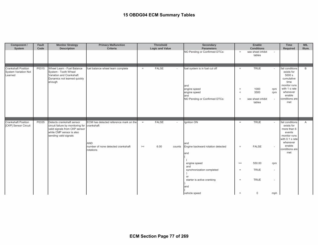
Component / Fault Monitor Strategy Primary Malfunction Secondary Time MILSystem Code Description Criteria Parameters Required Illum.
Threshold EnableLogic and Value Conditions
NO Pending or Confirmed DTCs: = see sheet inhibittables
-
Crankshaft PositionSystem Variation NotLearned
P0315 Wheel Learn - Fuel BalanceSystem - Tooth WheelVariation and CrankshaftDynamics not learned quicklyenough
fuel balance wheel learn complete = FALSE - fuel system is in fuel cut off = TRUE - B
andengine speed > 1000 rpmengine speed < 3500 rpmandNO Pending or Confirmed DTCs: = see sheet inhibit
tables-
Crankshaft Position[CKP] Sensor Circuit
P0335 Detects crankshaft sensorcircuit failure by monitoring forvalid signals from CKP sensorwhile CMP sensor is alsosending valid signals
ECM has detected reference mark on thecrankshaft
= FALSE - Ignition ON = TRUE - A
AND andnumber of none detected crankshaftrotations
>= 6.00 counts Engine backward rotation detected = FALSE -
and(
(engine speed >= 550.00 rpmandsynchronization completed = TRUE -)orstarter is active cranking = TRUE -
)and(vehicle speed = 0 mph
fail conditionsexists for5000 s
cumulativetime
monitor runswith 1 s ratewhenever
enableconditions are
met
fail conditionsexists for
more than 6events
monitor runswith 0.1 s rate
wheneverenable
conditions aremet
15 OBDG04 ECM Summary Tables
ECM Section Page 77 of 269

Component / Fault Monitor Strategy Primary Malfunction Secondary Time MILSystem Code Description Criteria Parameters Required Illum.
Threshold EnableLogic and Value Conditions
orvehicle speed > 16 mph
andengine speed > 200.00 rpm)andbasic enable conditions met: = see sheet enable
tables-
andNO Pending or Confirmed DTCs: = see sheet inhibit
tables-
Crankshaft PositionSensor Performance
P0336 Detects implausible crankshaftsensor operation by detectingincorrect crank sensor signalpatterns.
number of disturbances in crankshaftsignal
>= 3.00 counts Engine Running (see parameterdefinition)
= TRUE - A
crankshaft signal disturbance detectedunder the following conditions:
and
Current tooth time period > 200000.00 μsec ECM has detected reference mark on thecrankshaft
= FALSE -
or andCrankshaft tooth counts betweendetected gaps
> 68.00 counts basic enable conditions met: = see sheet enabletables
-
orIf gap not expected, ratio of currenttooth time to previous tooth time (seeLook-Up-Table #18)
> 1.5 to 2 ratio
orIf gap expected, ratio of current toothtime to previous tooth time (see Look-Up-Table #17)
> 3.38 to 8 ratio
Camshaft Position[CMP] Sensor Circuit
P0340 Detects camshaft sensorcircuit failure by monitoring forvalid signals from CMP sensorwhile CKP sensor is alsosending valid signals
number of crankshaft revolutions duringmissed camshaft signal
>= 2.50 counts NO pending or confirmed DTCs = see sheet inhibittables
- B
and
fail conditionsexists for 0.1
smonitor runs
with 0.1 s ratewhenever
enableconditions are
met
fail conditionsexists for
more than 3events
testperformed
continuously
15 OBDG04 ECM Summary Tables
ECM Section Page 78 of 269

Component / Fault Monitor Strategy Primary Malfunction Secondary Time MILSystem Code Description Criteria Parameters Required Illum.
Threshold EnableLogic and Value Conditions
ECM has detected reference mark on thecrankshaft
= TRUE -
andIgnition ON = TRUE -andengine synchronization operation is notfinished
= TRUE -
andbasic enable conditions met: = see sheet enable
tables-
Camshaft Position[CMP] SensorPerformance
P0341 Detects implausible camshaftsensor operation by detectingincorrect cam sensor patterns
number of camshaft edges > 6.00 counts NO pending or confirmed DTCs = see sheet inhibittables
- B
andECM has detected reference mark on thecrankshaft
= TRUE -
andIgnition ON = TRUE -andengine synchronization operation is notfinished
= TRUE -
andbasic enable conditions met: = see sheet enable
tables-
Glow Plug/HeaterIndicator ControlCircuit Low
P037A Diagnoses the Glow LampCircuit high side driver circuitfor circuit faults.
Voltage low during driver on state(indicates short-to-ground)
= Short to ground:≤ 0.5 Ωimpedancebetween signaland controllerground
- lamp is commanded on = TRUE - B
andbattery voltage > 11.00 V
fortime > 3.00 sec
and
0.01 s rate
fail conditionsexists for
more than 6events
testperformed
continuously0.01 s rate
fail conditionsexists for 3 smonitor runswith 0.01 s
rate wheneverenable
conditions aremet
15 OBDG04 ECM Summary Tables
ECM Section Page 79 of 269

Component / Fault Monitor Strategy Primary Malfunction Secondary Time MILSystem Code Description Criteria Parameters Required Illum.
Threshold EnableLogic and Value Conditions
basic enable conditions met: = see sheet enabletables
-
Glow Plug/HeaterIndicator ControlCircuit High
P037B Diagnoses the Glow LampCircuit high side driver circuitfor circuit faults.
Voltage high during driver off state(indicates short to power )
= Short to power: ≤0.5 Ω impedancebetween signaland controllerpower
- lamp is commanded on = FALSE - B
andbattery voltage > 11.00 V
fortime > 3.00 sec
andbasic enable conditions met: = see sheet enable
tables-
Glow Plug/HeaterIndicator ControlCircuit/Open
P0381 Diagnoses the Glow LampCircuit high side driver circuitfor circuit faults.
Voltage high during driver off state (opencircuit)
= Open Circuit: ≥200 K Ωimpedancebetween ECU pinand load signaland controllerground
- circuit active at low current = TRUE B
andbattery voltage > 11.00 V
fortime > 3.00 sec
andbasic enable conditions met: = see sheet enable
tables-
fail conditionsexists for 1 smonitor runswith 0.01 s
rate wheneverenable
conditions aremet
fail conditionsexists for 0.2
smonitor runswith 0.01 s
rate wheneverenable
conditions aremet
15 OBDG04 ECM Summary Tables
ECM Section Page 80 of 269
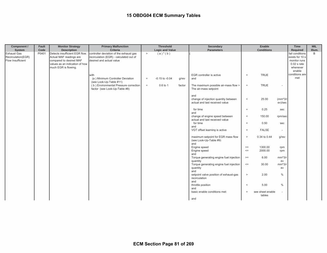
Component / Fault Monitor Strategy Primary Malfunction Secondary Time MILSystem Code Description Criteria Parameters Required Illum.
Threshold EnableLogic and Value Conditions
Exhaust GasRecirculation(EGR)Flow Insufficient
P0401 Detects insufficient EGR flow.Actual MAF readings arecompared to desired MAFvalues as an indication of howmuch EGR is flowing.
controller deviation of the exhaust gasrecirculation (EGR) - calculated out ofdesired and actual value
> ( a ) * ( b ) ( B
with EGR controller is active = TRUE (a ) Minimum Controller Deviation(see Look-Up-Table #11)
= -0.15 to -0.04 g/rev and
( b ) Environmental Pressure correctionfactor (see Look-Up-Table #8)
= 0.6 to 1 factor The maximum possible air-mass flow >The air-mass setpoint
= TRUE -
andchange of injection quantity betweenactual and last received value
< 25.00 (mm^3/rev)/sec
for time = 0.25 secandchange of engine speed betweenactual and last received value
< 150.00 rpm/sec
for time = 0.50 secandVGT offset learning is active = FALSE -
maximum setpoint for EGR mass flow(see Look-Up-Table #9)
> 0.34 to 0.44 g/rev
andEngine speed >= 1300.00 rpmEngine speed <= 2000.00 rpmandTorque generating engine fuel injectionquantity
>= 6.00 mm^3/rev
Torque generating engine fuel injectionquantity
<= 30.00 mm^3/rev
andsetpoint valve position of exhaust-gasrecirculation
> 2.00 %
andthrottle position < 5.00 %andbasic enable conditions met: = see sheet enable
tables-
and
fail conditionsexists for 10 smonitor runs0.02 s ratewhenever
enableconditions are
met
15 OBDG04 ECM Summary Tables
ECM Section Page 81 of 269
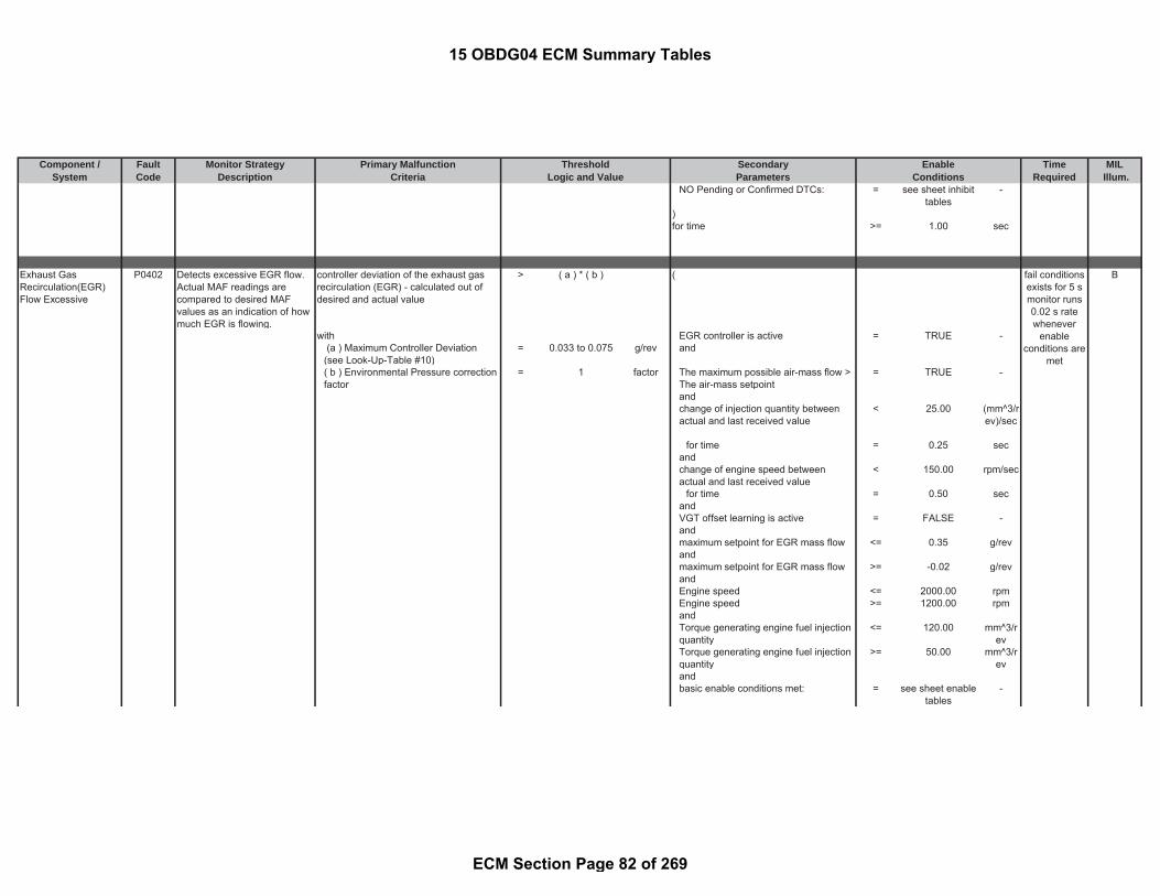
Component / Fault Monitor Strategy Primary Malfunction Secondary Time MILSystem Code Description Criteria Parameters Required Illum.
Threshold EnableLogic and Value Conditions
NO Pending or Confirmed DTCs: = see sheet inhibittables
-
)for time >= 1.00 sec
Exhaust GasRecirculation(EGR)Flow Excessive
P0402 Detects excessive EGR flow.Actual MAF readings arecompared to desired MAFvalues as an indication of howmuch EGR is flowing.
controller deviation of the exhaust gasrecirculation (EGR) - calculated out ofdesired and actual value
> ( a ) * ( b ) ( B
with EGR controller is active = TRUE - (a ) Maximum Controller Deviation(see Look-Up-Table #10)
= 0.033 to 0.075 g/rev and
( b ) Environmental Pressure correctionfactor
= 1 factor The maximum possible air-mass flow >The air-mass setpoint
= TRUE -
andchange of injection quantity betweenactual and last received value
< 25.00 (mm^3/rev)/sec
for time = 0.25 secandchange of engine speed betweenactual and last received value
< 150.00 rpm/sec
for time = 0.50 secandVGT offset learning is active = FALSE -andmaximum setpoint for EGR mass flow <= 0.35 g/revandmaximum setpoint for EGR mass flow >= -0.02 g/revandEngine speed <= 2000.00 rpmEngine speed >= 1200.00 rpmandTorque generating engine fuel injectionquantity
<= 120.00 mm^3/rev
Torque generating engine fuel injectionquantity
>= 50.00 mm^3/rev
andbasic enable conditions met: = see sheet enable
tables-
fail conditionsexists for 5 smonitor runs0.02 s ratewhenever
enableconditions are
met
15 OBDG04 ECM Summary Tables
ECM Section Page 82 of 269

Component / Fault Monitor Strategy Primary Malfunction Secondary Time MILSystem Code Description Criteria Parameters Required Illum.
Threshold EnableLogic and Value Conditions
andNO Pending or Confirmed DTCs: = see sheet inhibit
tables-
)for time >= 0.50 sec
Exhaust GasRecirculation (EGR)Motor Control Circuit
P0403 Diagnoses the EGR Valve lowside driver circuit for circuitfaults.
Voltage low during driver off state(indicates short-to-ground)
= Short to ground: 0.5
impedancebetween signaland controllerground
- EGR Solenoid Control Circuit = ACTIVE - B
andoffset learning for EGR valve iscompleted
= TRUE -
andbattery voltage > 11.00 V
fortime > 3.00 sec
andstarter is active cranking = FALSE -
fortime > 3.00 sec
andbasic enable conditions met: = see sheet enable
tables-
andNO Pending or Confirmed DTCs = see sheet inhibit
tables-
The ECM detects that the commandedstate of the driver and the actual state ofthe control circuit do not match.
EGR Solenoid Control Circuit = ACTIVE -
andoffset learning for EGR valve iscompleted
= TRUE -
andbattery voltage > 11.00 V
fail conditionsexists for 7 smonitor runswith 0.005 s
rate wheneverenable
conditions aremet
fail conditionsexists for 3 smonitor runswith 0.005 s
rate wheneverenable
conditions aremet
15 OBDG04 ECM Summary Tables
ECM Section Page 83 of 269

Component / Fault Monitor Strategy Primary Malfunction Secondary Time MILSystem Code Description Criteria Parameters Required Illum.
Threshold EnableLogic and Value Conditions
fortime > 3.00 sec
andstarter is active cranking = FALSE -
fortime > 3.00 sec
andbasic enable conditions met: = see sheet enable
tables-
andNO Pending or Confirmed DTCs = see sheet inhibit
tables-
Exhaust GasRecirculation(EGR)Position SensorCircuit Low Voltage
P0405 Detects low voltage readingson the EGR position sensorcircuit, indicating an OOR lowcondition on the EGR positionsensor circuit
voltage of EGR position sensor < 0.25 V ignition on = TRUE - B
same as andEGR actuator position < -25 % basic enable conditions met: = see sheet enable
tables-
andNO Pending or Confirmed DTCs: = see sheet inhibit
tables-
Exhaust GasRecirculation(EGR)Position SensorCircuit High Voltage
P0406 Detects high voltage readingson the EGR position sensorcircuit, indicating an OOR highcondition on the EGR positionsensor circuit
voltage of EGR position sensor > 4.80 V ignition on = TRUE - B
same as andEGR actuator position > 127 % basic enable conditions met: = see sheet enable
tables-
andNO Pending or Confirmed DTCs: = see sheet inhibit
tables-
fail conditionsexists for 5 s
testperformed
continuously0.005 s rate
fail conditionsexists for 5 s
testperformed
continuously0.005 s rate
15 OBDG04 ECM Summary Tables
ECM Section Page 84 of 269

Component / Fault Monitor Strategy Primary Malfunction Secondary Time MILSystem Code Description Criteria Parameters Required Illum.
Threshold EnableLogic and Value Conditions
Exhaust GasRecirculation(EGR)Temperature SensorA Circuit Low Voltage
P040C Detects low voltage readingson the EGR coolertemperature circuit, indicatingan OOR low condition on theEGR cooler temperature 2circuit
EGR temperature sensor 2 voltage < 0.14 V ( B
same as time since engine start > 0.00 secEGR sensor 2 temperature > 1000 °C and
engine coolant temperature < 199.96 °Candambient temperature > -60.04 °Candambient pressure > 20.00 kPaand(setpoint valve position of exhaust-gasrecirculation
> -100.00 %
andsetpoint valve position of exhaust-gasrecirculation
< 200.00 %
)andEngine Running (see parameterdefinition)
= TRUE -
and(valve position of EGR cooler bypass > -100.00 %andvalve position of EGR cooler bypass < 200.00 %andbasic enable conditions met: = see sheet enable
tables-
andNO Pending or Confirmed DTCs: = see sheet inhibit
tables-
fail conditionsexists for 5 smonitor runs0.05 s ratewhenever
enableconditions are
met
15 OBDG04 ECM Summary Tables
ECM Section Page 85 of 269

Component / Fault Monitor Strategy Primary Malfunction Secondary Time MILSystem Code Description Criteria Parameters Required Illum.
Threshold EnableLogic and Value Conditions
Exhaust GasRecirculation(EGR)Temperature SensorA Circuit High Voltage
P040D Detects high voltage readingson the EGR temperaturecooler circuit, indicating anOOR high condition on theEGR cooler temperature 2circuit
EGR temperature sensor 2 voltage > 4.98 V ( B
same as (EGR sensor 2 temperature < -45 °C ambient temperature > -10.04 °C
ortime since engine start > 100.00 sec
)andengine coolant temperature > -60.04 °Candambient pressure > 20.00 kPaand(setpoint valve position of exhaust-gasrecirculation
> -100.00 %
andsetpoint valve position of exhaust-gasrecirculation
< 200.00 %
)andEngine Running (see parameterdefinition)
= TRUE -
andcurrent injection quantity > 0.00 mm^3/r
evand(valve position of EGR cooler bypass > -100.00 %andvalve position of EGR cooler bypass < 200.00 %))andbasic enable conditions met: = see sheet enable
tables-
andNO Pending or Confirmed DTCs: = see sheet inhibit
tables-
fail conditionsexists for 5 smonitor runs0.05 s ratewhenever
enableconditions are
met
15 OBDG04 ECM Summary Tables
ECM Section Page 86 of 269

Component / Fault Monitor Strategy Primary Malfunction Secondary Time MILSystem Code Description Criteria Parameters Required Illum.
Threshold EnableLogic and Value Conditions
Exhaust GasRecirculation(EGR)Temperature SensorCorrelation (EGR 1/EGR 2)
P040F Detects biased EGRtemperature sensors bycomparing the two EGR coolertemp sensor after an engineoff soak time
Path 1: minimum engine-off time >= 28800.00 sec B
|(a) - (b)| (see Look-Up-Table #4) > 20 to 3276.7 °C andwith ambient temperature > -7.04 °C
(a) captured EGR sensor 2 temperatureat start
= measuredparameter
- and
and with Engine Running (see parameterdefinition)
= TRUE -
(b) captured EGR sensor 1 temperatureat start
= measuredparameter
- for
or time > 0.10 secandengine post drive/ afterun = FALSE
anddiagnostic performed in current dc = FALSEandbasic enable conditions met: = see sheet enable
tables-
andNO Pending or Confirmed DTCs: = see sheet inhibit
tables-
Exhaust GasRecirculation(EGR)Temperature SensorB Circuit Low Voltage
P041C Detects low voltage readingson the EGR coolertemperature circuit, indicatingan OOR low condition on theEGR cooler temperature 1circuit
voltage of EGR temperature sensor 1 < 0.13 V ( B
same as time since engine start > 0.00 secEGR sensor 1 temperature > 1000 °C and
engine coolant temperature < 199.96 °Candambient temperature > -60.04 °Candambient pressure > 20.00 kPa
fail conditionsexists for 0.1
smonitor runs
with 0.1 s ratewhenever
enableconditions are
met
fail conditionsexists for 5 smonitor runs0.05 s ratewhenever
enableconditions are
met
15 OBDG04 ECM Summary Tables
ECM Section Page 87 of 269
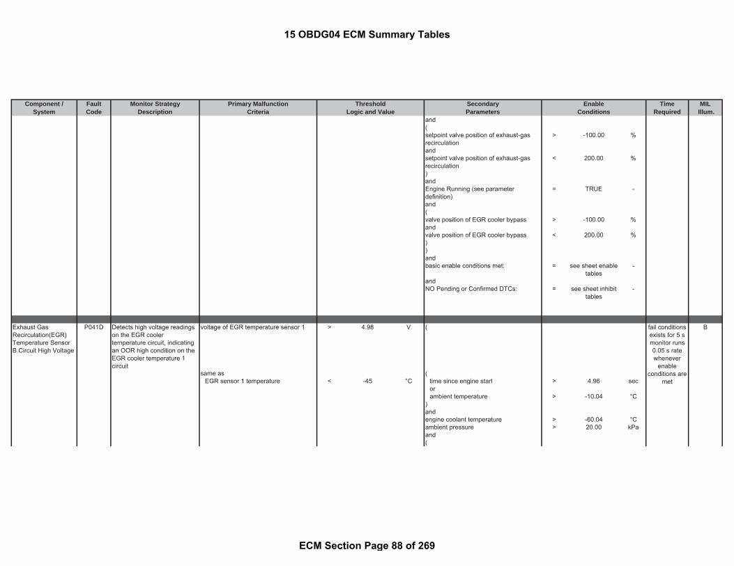
Component / Fault Monitor Strategy Primary Malfunction Secondary Time MILSystem Code Description Criteria Parameters Required Illum.
Threshold EnableLogic and Value Conditions
and(setpoint valve position of exhaust-gasrecirculation
> -100.00 %
andsetpoint valve position of exhaust-gasrecirculation
< 200.00 %
)andEngine Running (see parameterdefinition)
= TRUE -
and(valve position of EGR cooler bypass > -100.00 %andvalve position of EGR cooler bypass < 200.00 %))andbasic enable conditions met: = see sheet enable
tables-
andNO Pending or Confirmed DTCs: = see sheet inhibit
tables-
Exhaust GasRecirculation(EGR)Temperature SensorB Circuit High Voltage
P041D Detects high voltage readingson the EGR coolertemperature circuit, indicatingan OOR high condition on theEGR cooler temperature 1circuit
voltage of EGR temperature sensor 1 > 4.98 V ( B
same as (EGR sensor 1 temperature < -45 °C time since engine start > 4.96 sec
orambient temperature > -10.04 °C
)andengine coolant temperature > -60.04 °Cambient pressure > 20.00 kPaand(
fail conditionsexists for 5 smonitor runs0.05 s ratewhenever
enableconditions are
met
15 OBDG04 ECM Summary Tables
ECM Section Page 88 of 269

Component / Fault Monitor Strategy Primary Malfunction Secondary Time MILSystem Code Description Criteria Parameters Required Illum.
Threshold EnableLogic and Value Conditions
setpoint valve position of exhaust-gasrecirculation
> -100.00 %
andsetpoint valve position of exhaust-gasrecirculation
< 200.00 %
)andEngine Running (see parameterdefinition)
= TRUE -
andcurrent injection quantity > 0.00 mm^3/r
evand(valve position of EGR cooler bypass > -100.00 %andvalve position of EGR cooler bypass < 200.00 %))
fortime > 0.01 sec
andbasic enable conditions met: = see sheet enable
tables-
andNO Pending or Confirmed DTCs: = see sheet inhibit
tables-
NMHC CatalystEfficiency BelowThreshold Bank 1
P0420 Detects insufficient conversionrate in oxidation catalyst.Actual conversion rate iscompared to a conversion ratethreshold as an indication ofhow much HC is converted inthe oxidation catalyst.
Calculated HC conversion rate < 0.25 - Stage 2 Rapid Heat-up Injection Mode
Rapid Heat-up is a catalyst heatingstrategy. Stage 2 refers to stage ofRapid-Heat-Up where both PoI1 andPoI2 are injected which results inexotherm across DOC
= TRUE - B
andmonitor already enabled this drive cycle(i.e. once per trip)
= FALSE -
and(
fail conditionsexists for
more than 0.1seconds
monitor runsonce per
driving cyclewith 0.1 s rate
wheneverenable
conditions aremet
15 OBDG04 ECM Summary Tables
ECM Section Page 89 of 269
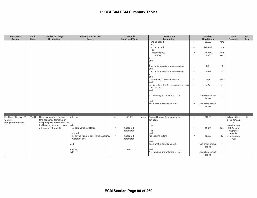
Component / Fault Monitor Strategy Primary Malfunction Secondary Time MILSystem Code Description Criteria Parameters Required Illum.
Threshold EnableLogic and Value Conditions
engine speed > 500.00 rpmandengine speed <= 2850.00 rpm
orengine speed > 2850.00 rpm
for time < 2,00 sec)and(Coolant temperature at engine start > -7.04 °CandCoolant temperature at engine start <= 35.96 °C)andtime with DOC monitor released < 200 secandintegrated modeled combusted fuel massflow into DOC
> 5.00 g
and
NO Pending or Confirmed DTCs: = see sheet inhibittables
-
andbasic enable conditions met: = see sheet enable
tables-
Fuel Level Sensor "A"CircuitRange/Performance
P0461 (a) - (b) >= 149.13 miles Engine Running (see parameterdefinition)
= TRUE - B
with for(a) total vehicle distance = measured
parameter-
time> 60.00 sec
and with and(b) saved value of total vehicle distanceat start of test
= measuredparameter
- fuel volume in tank < 100.00 %
andand basic enable conditions met: see sheet enable
tables-
(c) - (d) < 3.00 L andwith NO Pending or Confirmed DTCs: see sheet inhibit
tables-
Detects an error in the fueltank sensor performance bycomparing the decrease of thefuel level for a certain drivenmileage to a threshold.
fail conditionsexists for 0.02
smonitor runs0.02 s ratewhenever
enableconditions are
met
15 OBDG04 ECM Summary Tables
ECM Section Page 90 of 269

Component / Fault Monitor Strategy Primary Malfunction Secondary Time MILSystem Code Description Criteria Parameters Required Illum.
Threshold EnableLogic and Value Conditions
(c) maximum volume of fuel reached intank during test
= measuredparameter
-
and with(d) minimum volume of fuel reached intank during test
= measuredparameter
-
Fuel Level Sensor 1Circuit Low
P0462 Detects low voltage readingson the fuel level sensor circuit,indicating an OOR lowcondition on the circuit
voltage of fuel level sensor 1 < 0.48 V ignition on = TRUE - B
same as andfuel level > 59.05 L basic enable conditions met: = see sheet enable
tables-
Fuel Level Sensor 1Circuit High
P0463 Detects high voltage readingson the fuel level sensor circuit,indicating an OOR highcondition on the circuit
voltage of fuel level sensor 1 > 2.80 V ignition on = TRUE - B
same as andfuel level < 0.00 L basic enable conditions met: = see sheet enable
tables-
Exhaust GasRecirculation (EGR)Position SensorPerformance
P046C Detects in range EGR valveposition errors by comparingdesired EGR position to actualEGR valve position
controller deviation of EGR valvecalculated out of difference betweendesired and actual value
>= 5.00 % offset learning of EGR actuator active = FALSE - Bfail conditionsexists for 8 smonitor runswith 0.02 s
rate whenever
fail conditionsexists for 8 s
testperformed
continuously0.01 s rate
fail conditionsexists for 8 s
testperformed
continuously0.01 s rate
15 OBDG04 ECM Summary Tables
ECM Section Page 91 of 269

Component / Fault Monitor Strategy Primary Malfunction Secondary Time MILSystem Code Description Criteria Parameters Required Illum.
Threshold EnableLogic and Value Conditions
or andcontroller deviation of EGR valvecalculated out of difference betweendesired and actual value
<= -5.00 % offset learning in the previous drivingcycle was complete
= TRUE -
andEngine is in the normal state = TRUE -andduty cycle of the Intake Air Heater output < 327.67 %
andbattery voltage >= 11.00 VandThe position control is active = FALSE -andEGR Valve Jammed = FALSE -andEGR Valve Jammed = TRUE -andNO Pending or Confirmed DTCs: = see sheet inhibit
tables-
basic enable conditions met: = see sheet enabletables
-
Fan 1 Control Circuit P0480 Diagnoses the Cooling Fanlow side driver circuit for circuitfaults.
Voltage low during driver off state(indicates open circuit)
= Open Circuit:≥200 K Ωimpedancebetween ECU pinand load
- battery voltage > 11.00 V B
for
time > 3.00 secandstarter is active cranking = FALSE -
fortime > 3.00 sec
andignition on = TRUE -andbasic enable conditions met: = see sheet enable
tables-
NO Pending or Confirmed DTCs: = see sheet inhibittables
-
enableconditions are
met
fail conditionsexists for 3 s
testperformed
continuously0.02 s rate
15 OBDG04 ECM Summary Tables
ECM Section Page 92 of 269

Component / Fault Monitor Strategy Primary Malfunction Secondary Time MILSystem Code Description Criteria Parameters Required Illum.
Threshold EnableLogic and Value Conditions
Exhaust GasRecirculation (EGR)Motor Control Circuit 1Low Voltage
P0489 Diagnoses the EGR Valve lowside driver circuit for circuitfaults.
Voltage low during driver off state(indicates short-to-ground)
= Short to ground: 0.5
impedancebetween signaland controllerground
- EGR Solenoid Control Circuit = ACTIVE - B
andbattery voltage > 11.00 V
for
time > 3.00 secandstarter is active cranking = FALSE -
fortime > 3.00 sec
andignition on = TRUE -andbasic enable conditions met: = see sheet enable
tables-
NO Pending or Confirmed DTCs: = see sheet inhibittables
-
Exhaust GasRecirculation (EGR)Motor Control Circuit 1High Voltage
P0490 Diagnoses the EGR Valve lowside driver circuit for circuitfaults.
Voltage high during driver on state(indicates short to power)
= Short to power: ≤ 0.5 Ωimpedancebetween signaland controllerpower
- EGR Solenoid Control Circuit = ACTIVE - B
andbattery voltage > 11.00 V
for
time > 3.00 secandstarter is active cranking = FALSE -
fail conditionsexists for 3 smonitor runswith 0.005 s
rate wheneverenable
conditions aremet
fail conditionsexists for 3 smonitor runswith 0.005 s
rate wheneverenable
conditions aremet
15 OBDG04 ECM Summary Tables
ECM Section Page 93 of 269

Component / Fault Monitor Strategy Primary Malfunction Secondary Time MILSystem Code Description Criteria Parameters Required Illum.
Threshold EnableLogic and Value Conditions
fortime > 3.00 sec
andignition on = TRUE -andbasic enable conditions met: = see sheet enable
tables-
NO Pending or Confirmed DTCs: = see sheet inhibittables
-
Exhaust GasRecirculation (EGR)Control Position NotLearned
P049D Detects adaptation values ofEGR valve are not plausible.Compares the differencebetween the maximum andminimum adaptation values toa threshold.
Path 1: offset learning finished = FALSE - B
the difference between the maximumvalue of the read position (a) and theminimum value of the read position (b)
> 5.00 % and
with ((a) maximum learned offset value forEGR valve
= measuredparameter
- engine coolant temperature >= 69.96 °C
and with and(b) minimum learned offset value forEGR valve
= measuredparameter
- engine coolant temperature <= 127.96 °C
or )Path 2: and( (learned offset value for EGR valve in thepresent driving cycle
> 10.00 % battery voltage >= 11.00 V
or andlearned offset value for EGR valve in thepresent driving cycle
< -10.00 % battery voltage <= 655.34 V
) )andEGR sweep has ended - no movementin EGR valve
= TRUE -
andengine post drive/ afterun = TRUE -and
fail conditionsexists for0.005 s
monitor runswith 0.005 s
rate wheneverenable
conditions aremet
15 OBDG04 ECM Summary Tables
ECM Section Page 94 of 269

Component / Fault Monitor Strategy Primary Malfunction Secondary Time MILSystem Code Description Criteria Parameters Required Illum.
Threshold EnableLogic and Value Conditions
engine was running during last drivingcycle
= TRUE -
andNO Pending or Confirmed DTCs: see sheet inhibit
tables
Detects a jammed EGR valveduring opening or closing thevalve.
Path 1:offset learning active = TRUE
-
EGR valve stuck during opening = TRUE andmeans engine post drive/ afterun = TRUE -
( and( ((a) + (b) >= 20.00 % Path 1:with EGR valve is opening = TRUE -
(a) position of EGR valve = measuredparameter
- or
and with Path 2:(b) learned offset value of EGR valvein the previous driving cycle
= calculatedparameter
- EGR valve is closing = TRUE -
) )and(
(a) - (c) <= 0.01 %with
(a) position of EGR valve = measuredparameter
-
and with(c) position of EGR valve of previousprocess cycle
= calculatedparameter
-
))fortime > 5.00 secorPath 2:EGR valve stuck during closing = TRUEmeans(( 110.00 %
(a) * (b) >
fail conditionsexists for0.005 s
monitor runswith 0.005 s
rate wheneverenable
conditions aremet
15 OBDG04 ECM Summary Tables
ECM Section Page 95 of 269

Component / Fault Monitor Strategy Primary Malfunction Secondary Time MILSystem Code Description Criteria Parameters Required Illum.
Threshold EnableLogic and Value Conditions
with(a) reference position of the EGRvalve in open position
= calculatedparameter
-
and with(b) factor for EGR valve close position = 0.20 factor
)and(
|(c) - (d)| <= 100.00 %with
(c) position of EGR valve = measuredparameter
-
and with(d) position of EGR valve of previousprocess cycle
= calculatedparameter
-
))fortime > 5.00 sec
Idle Speed Too Low P0506 Detects an idle speedgovernor that is unable toachieve the desired idle speedand the idle speed is too low
engine speed < maximum valueof (a) OR (b - (b *c))
engine speed (see Look-Up-Table #81) >= 850 to 1100 rpm B
with and(a) minimum engine speed = 300.00 rpm (and with engine coolant temperature < 125.96 °C(b) minimum idle speed setpoint = calculated
parameter- and
and with engine coolant temperature > -7.04 °C(c) factor for calculation of enginespeed interval
= 24.00 % )
andidle speed controller active = TRUE -andvehicle speed < 1.86 mphandno other torque demanding functionactive
= TRUE -
fail conditionsexists for 15 smonitor runs
with 0.1 s ratewhenever
enableconditions are
met
15 OBDG04 ECM Summary Tables
ECM Section Page 96 of 269

Component / Fault Monitor Strategy Primary Malfunction Secondary Time MILSystem Code Description Criteria Parameters Required Illum.
Threshold EnableLogic and Value Conditions
andsetpoint torque of the speed controller > 0 NMandengine speed > 300.00 rpmandbasic enable conditions met: = see sheet enable
tables-
andNO Pending or Confirmed DTCs: = see sheet inhibit
tables-
Idle Speed Too High P0507 Detects an idle speedgovernor that is unable toachieve the desired idle speedand the idle speed is too high.
engine speed > minimum valueof (a) OR (b + (b* c))
engine speed (see Look-Up-Table #81) >= 850 to 1100 rpm B
with and(a) maximum engine speed = 2500.00 rpm (and with engine coolant temperature < 125.96 °C(b) minimum idle speed setpoint = calculated
parameter- and
and with engine coolant temperature > -7.04 °C(c) factor for calculation of enginespeed interval
= 24.00 % )
andidle speed controller active = TRUE -andvehicle speed < 1.86 mphandno other torque demanding functionactive
= TRUE -
andsetpoint torque of the speed controller > 0 NMandengine speed > 300.00 rpmandbasic enable conditions met: = see sheet enable
tables-
andNO Pending or Confirmed DTCs: = see sheet inhibit
tables-
fail conditionsexists for 15 smonitor runs
with 0.1 s ratewhenever
enableconditions are
met
15 OBDG04 ECM Summary Tables
ECM Section Page 97 of 269

Component / Fault Monitor Strategy Primary Malfunction Secondary Time MILSystem Code Description Criteria Parameters Required Illum.
Threshold EnableLogic and Value Conditions
Exhaust GasTemperature (EGT)Sensor 1 Circuit LowVoltage
P0545 Detects low voltage readingson the EGT 1 circuit, indicatingan OOR low condition on theEGT circuit
voltage of the temperature sensorupstream of oxidation catalyst
< 0.55 V NO Pending or Confirmed DTCs: = see sheet inhibittables
- B
same as fortemperature upstream of oxidationcatalyst
< -50 °C time > 0.00 sec
andignition on = TRUE -andbasic enable conditions met: = see sheet enable
tables-
Exhaust GasTemperature (EGT)Sensor 1 Circuit HighVoltage
P0546 Detects high voltage readingson the EGT 1 circuit, indicatingan OOR high condition on theEGT 1 circuit
voltage of the temperature sensorupstream of oxidation catalyst
> 2.33 V NO Pending or Confirmed DTCs: = see sheet inhibittables
- B
same as fortemperature upstream of oxidationcatalyst
> 1000 °C time > 0.00 sec
andignition on = TRUE -andbasic enable conditions met: = see sheet enable
tables-
fail conditionsexists for 5 smonitor runs0.050 s ratewhenever
enableconditions are
met
fail conditionsexists for 5 smonitor runs0.050 s ratewhenever
enableconditions are
met
15 OBDG04 ECM Summary Tables
ECM Section Page 98 of 269
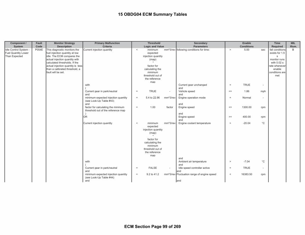
Component / Fault Monitor Strategy Primary Malfunction Secondary Time MILSystem Code Description Criteria Parameters Required Illum.
Threshold EnableLogic and Value Conditions
Idle Control System -Fuel Quantity LowerThan Expected
P054E This diagnostic monitors thefuel injection quantity at lowidle. The ECM compares theactual injection quantity withcalculated thresholds. If theactual injection quantity is lessthan a calibrated threshold, afault will be set.
Current injection quantity < minimumexpected
injection quantity(map)
*factor for
calculating theminimum
threshold out ofthe reference
map
mm^3/rev following conditions for time: > 5.00 sec B
with Current gear unchanged = TRUE -( andCurrent gear in park/neutral = TRUE - Vehicle speed <= 1.86 mphand andminimum expected injection quantity(see Look-Up Table #43)
= 5.4 to 22.96 mm^3/rev Engine operation mode = Normal -
and andfactor for calculating the minimumthreshold out of the reference map
= 1.00 factor Engine speed <= 1300.00 rpm
) andOR Engine speed >= 400.00 rpm
andCurrent injection quantity < minimum
expectedinjection quantity
(map) *
factor forcalculating the
minimumthreshold out ofthe reference
map
mm^3/rev Engine coolant temperature > -20.04 °C
andwith Ambient air temperature > -7.04 °C( andCurrent gear in park/neutral = FALSE - Idle speed controller active = TRUE -and andminimum expected injection quantity(see Look-Up Table #44)
= 9.2 to 41.2 mm^3/rev Fluctuation range of engine speed < 16383.50 rpm
and and
fail conditionsexists for 1.5
smonitor runswith 0.02 s
rate wheneverenable
conditions aremet
15 OBDG04 ECM Summary Tables
ECM Section Page 99 of 269

Component / Fault Monitor Strategy Primary Malfunction Secondary Time MILSystem Code Description Criteria Parameters Required Illum.
Threshold EnableLogic and Value Conditions
factor for calculating the minimumthreshold out of the reference map
= 1.00 factor NO Pending or Confirmed DTCs: = see sheet inhibittables
-
) andbasic enable conditions met: = see sheet enable
tables-
Idle Control System -Fuel Quantity HigherThan Expected
P054F This diagnostic monitors thefuel injection quantity at lowidle. The ECM compares theactual injection quantity withcalculated thresholds. If theactual injection quantity isgreater than a calibratedthreshold, a fault will be set.
Current injection quantity > maximumexpected
injection quantity(map)
*factor for
calculating themaximum
threshold out ofthe reference
map
mm^3/rev following conditions for time: > 5.00 sec B
with Current gear unchanged = TRUE -( andCurrent gear in park/neutral = TRUE - Vehicle speed <= 1.86 mphand andmaximum expected injection quantity(see Look-Up-Table #42)
= 60.2 to 111.8 mm^3/rev Engine operation mode = TRUE -
and andfactor for calculating the maximumthreshold out of the reference map
= 1.00 factor Engine speed <= 1300.00 rpm
) andOR Engine speed >= 400.00 rpm
and
fail conditionsexists for 1.5
smonitor runswith 0.02 s
rate wheneverenable
conditions aremet
15 OBDG04 ECM Summary Tables
ECM Section Page 100 of 269

Component / Fault Monitor Strategy Primary Malfunction Secondary Time MILSystem Code Description Criteria Parameters Required Illum.
Threshold EnableLogic and Value Conditions
Current injection quantity > maximumexpected
injection quantity(map)
*factor for
calculating themaximum
threshold out ofthe reference
map
mm^3/rev Engine coolant temperature > -20.04 °C
with and( Ambient air temperature > -7.04 °CCurrent gear in park/neutral = FALSE - andand Idle speed controller active = TRUE -maximum expected injection quantity(see Look-Up-Table #41)
= 81.2 to 176.8 mm^3/rev and
and Fluctuation range of engine speed < 16383.50 rpmfactor for calculating the maximumthreshold out of the reference map
= 1.00 factor and
) NO Pending or Confirmed DTCs: = see sheet inhibittables
-
andbasic enable conditions met: = see sheet enable
tables-
Cruise Control Multi-Function Input "A"Circuit
P0564 Set illegal range indicatesproblem on status of the cruiseswitch information
Switch state provided by Cruise Controlframe
= ILLEGALRANGE
- ignition on = TRUE - Special C
andbasic enable conditions met = see sheet enable
tables-
andNO Pending or Confirmed DTCs: = see sheet enable
tables-
fail conditionsexists for 2.5
smonitor runswith 0.005 s
rate wheneverenable
conditions aremet
15 OBDG04 ECM Summary Tables
ECM Section Page 101 of 269

Component / Fault Monitor Strategy Primary Malfunction Secondary Time MILSystem Code Description Criteria Parameters Required Illum.
Threshold EnableLogic and Value Conditions
Cruise ControlResume Switch Circuit
P0567 Resume switch state indicatesproblem with the circuit
Resume Switch CAN message in high /active state
= TRUE - ignition on = TRUE - Special C
andinput circuit active = TRUE -andbasic enable conditions met = see sheet enable
tables-
andNO Pending or Confirmed DTCs: = see sheet inhibit
tables-
Cruise Control SetSwitch Circuit
P0568 Set switch state indicatesproblem with the circuit
Set Switch CAN message in high / activestate
= TRUE - ignition on = TRUE - Special C
andinput circuit active = TRUE -andbasic enable conditions met = see sheet enable
tables-
andNO Pending or Confirmed DTCs: = see sheet inhibit
tables-
Cruise Control InputCircuit
P0575 Cruise control CANcommunication monitoring
amount of errors in consecutive frames >= 3.00 counts ignition on = TRUE - Special C
with andnumber of consecutive frames = 10.00 counts input circuit active = TRUE -
andbasic enable conditions met = see sheet enable
tables-
andNO Pending or Confirmed DTCs: = see sheet inhibit
tables-
fail conditionsexists for 90 smonitor runswith 0.005 s
rate wheneverenable
conditions aremet
fail conditionsexists for 90 smonitor runswith 0.005 s
rate wheneverenable
conditions aremet
fail conditionsexists for0.005 s
monitor runswith 0.005 s
rate wheneverenable
conditions aremet
15 OBDG04 ECM Summary Tables
ECM Section Page 102 of 269

Component / Fault Monitor Strategy Primary Malfunction Secondary Time MILSystem Code Description Criteria Parameters Required Illum.
Threshold EnableLogic and Value Conditions
Brake Pedal PositionSensor "A" CircuitRange/Performance
P057B Compare maximum delta ofanalog brake pedal sensorwith a threshold
EWMA filtered test result based on thedifference of |(a) - (b)|
<= 0.40 factor following conditions for time: > 4 sec A
where ((a) maximum analog brake sensor rawvoltage during test
= calculatedparameter
V ignition on = TRUE -
(b) minimum analog brake sensor rawvoltage during test
= calculatedparameter
V and
where starter is active cranking = FALSE -difference of the brake sensor voltagecorresponds to a corrected value of(see Look-Up-Table #13)
= 0 to 1 factor for
time > 3.00 secandbattery voltage > 11.00 Vfortime > 3.00 sec)
andgear has been in Park during this drivingcycle
= TRUE -
full test has not been completed thisdriving cycle
= TRUE -
gear selector currently not in Park = TRUE -vehicle speed >= 4.35 mphaccelerator pedal position 1 < 5.00 %andNo Pending or Confirmed DTCs: = see sheet inhibit
tables-
andbasic enable conditions met: = see sheet enable
tables-
Brake Pedal PositionSensor "A" Circuit Low
P057C Brake pedal position sensorvoltage below a threshold for acalibrated period of timeindicating an OOR low
Brake pedal position sensor voltage < 0.25 V ignition on = TRUE - A
andNo Pending or Confirmed DTCs: = see sheet inhibit
tables-
monitor runs0.02 s ratewhenever
enableconditions are
met
fail conditionsexists for 0.5
smonitor runs0.01 s ratewhenever
enable
15 OBDG04 ECM Summary Tables
ECM Section Page 103 of 269
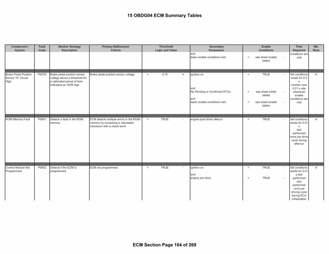
Component / Fault Monitor Strategy Primary Malfunction Secondary Time MILSystem Code Description Criteria Parameters Required Illum.
Threshold EnableLogic and Value Conditions
andbasic enable conditions met: = see sheet enable
tables-
Brake Pedal PositionSensor "A" CircuitHigh
P057D Brake pedal position sensorvoltage above a threshold fora calibrated period of timeindicating an OOR high
Brake pedal position sensor voltage > 4.75 V ignition on = TRUE - A
andNo Pending or Confirmed DTCs: = see sheet inhibit
tables-
andbasic enable conditions met: = see sheet enable
tables-
ROM Memory Fault P0601 Detects a fault in the ROMmemory
ECM detects multiple errors in the ROM-memory by comparing a calculatedchecksum with a check word
= TRUE - engine post drive/ afterun = TRUE - A
Control Module NotProgrammed
P0602 Detects if the ECM isprogrammed.
ECM not programmed = TRUE - ignition on = TRUE - A
andengine pre drive = TRUE -
fail conditionsexists for 0.5
smonitor runs0.01 s ratewhenever
enableconditions are
met
fail conditionsexists for 0.01
stest
performedonce per drivecycle during
afterrun
fail conditionsexists for 0.01
s testperformed
testperformedonce per
driving cycleduring ECUinitialization
conditions aremet
15 OBDG04 ECM Summary Tables
ECM Section Page 104 of 269

Component / Fault Monitor Strategy Primary Malfunction Secondary Time MILSystem Code Description Criteria Parameters Required Illum.
Threshold EnableLogic and Value Conditions
Control ModuleInternal Performance
P0606 Monitors and detects theimproper operation of theECM. This is accomplished bymonitoring the output ofvarious hardware moduleswithin the ECM and bycreating parallel redundantcalculations of critical enginemanagement systemparameters.
Error on starting DC/DC converter of onebank piezo power stage
= TRUE - ignition on = TRUE - A
andDC/DC converter is in startup = TRUE -
Monitors and detects theimproper operation of theECM. This is accomplished bymonitoring the output ofvarious hardware moduleswithin the ECM and bycreating parallel redundantcalculations of critical enginemanagement systemparameters.
DC/DC converter of one bank cannot beswitched off
= TRUE - ignition on = TRUE - fail conditionsexists for 0.1smonitor runswith 0.01 srate wheneverenableconditions aremet
fail conditionsexists for 0.01
smonitor runswith 0.01 s
rate wheneverenable
conditions aremet
15 OBDG04 ECM Summary Tables
ECM Section Page 105 of 269
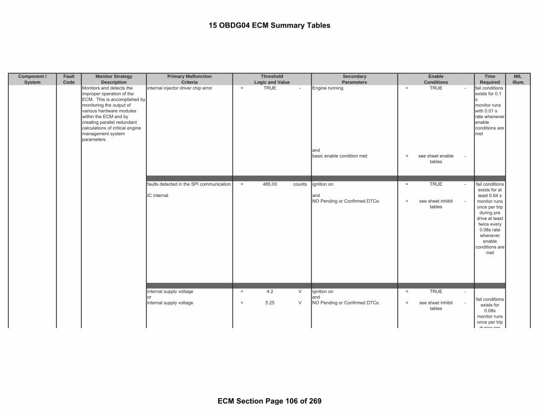
Component / Fault Monitor Strategy Primary Malfunction Secondary Time MILSystem Code Description Criteria Parameters Required Illum.
Threshold EnableLogic and Value Conditions
Monitors and detects theimproper operation of theECM. This is accomplished bymonitoring the output ofvarious hardware moduleswithin the ECM and bycreating parallel redundantcalculations of critical enginemanagement systemparameters.
internal injector driver chip error = TRUE - Engine running = TRUE - fail conditionsexists for 0.1smonitor runswith 0.01 srate wheneverenableconditions aremet
andbasic enable condition met: = see sheet enable
tables-
faults detected in the SPI communication > 485.00 counts ignition on = TRUE -
IC internal andNO Pending or Confirmed DTCs: = see sheet inhibit
tables-
internal supply voltage < 4.2 V ignition on = TRUE -or andinternal supply voltage > 5.25 V NO Pending or Confirmed DTCs: = see sheet inhibit
tables-
fail conditionsexists for atleast 0.64 smonitor runsonce per tripduring pre
drive at leasttwice every0.08s ratewhenever
enableconditions are
met
fail conditionsexists for
0.08smonitor runsonce per tripduring pre
15 OBDG04 ECM Summary Tables
ECM Section Page 106 of 269

Component / Fault Monitor Strategy Primary Malfunction Secondary Time MILSystem Code Description Criteria Parameters Required Illum.
Threshold EnableLogic and Value Conditions
|(a) - (b)| > 72.00 μsec programmed energizing time for fuelinjection has been read back
= TRUE -
with means(a) parallel redundant calculation ofenergizing time for fuel injection
= calculatedparameter
- programmed energizing time for fuelinjection
>= 0 -
and with and(b) parallel redundant calculation ofprogrammed energizing time for fuelinjection
= calculatedparameter
- measured energizing time for fuelinjection has been read back
= TRUE -
meansmeasured energizing time for fuelinjection
>= 0 -
andengine speed > 1200.00 rpmandrail pressure > 20000.00 kPaandengine test active via diagnosis tester = FALSE -and
Path 1: engine speed > 1200.00 rpm( andparallel redundant calculation of anglefor pilot injection 1 quantity
< -37.99 degrees engine test active via diagnosis tester = FALSE
orparallel redundant calculation of anglefor pilot injection 1 quantity
> 44.98 degrees
)or
during predrive at leasttwice every0.08s ratewhenever
enableconditions are
met
fail conditionsexists for atleast 0.05 smonitor runswith 0.01 s
rate wheneverenable
conditions aremet
fail conditionsexists for atleast 0.05 smonitor runswith 0.01 s
rate wheneverenable
conditions aremet
15 OBDG04 ECM Summary Tables
ECM Section Page 107 of 269

Component / Fault Monitor Strategy Primary Malfunction Secondary Time MILSystem Code Description Criteria Parameters Required Illum.
Threshold EnableLogic and Value Conditions
Path 2:(parallel redundant calculation of anglefor main injection quantity
< -37.99 degrees
orparallel redundant calculation of anglefor main injection quantity
> 32.98 degrees
)orPath 3:
(parallel redundant calculation of anglefor post injection quantity 1
< -360.00 degrees
orparallel redundant calculation of anglefor post injection quantity 1
> -67.00 degrees
)orPath 4:
(parallel redundant calculation of anglefor post injection quantity 2
< -183.00 degrees
orparallel redundant calculation of anglefor post injection quantity 2
> 32.98 degrees
)orPath 5:(
parallel redundant calculation of anglefor post injection quantity 3
< -183.00 degrees
orparallel redundant calculation of anglefor post injection quantity 3
> 0.00 degrees
)
( redundant engine speed calculation >= 1200.00 rpmparallel redundant calculation ofenergizing times of the correction valuefor pilot injection quantity (see Look-Up-Table #54)
< -500 to -50 μsec andfail conditionsexists for atleast 0.2 s
monitor runswith 0.04 s
15 OBDG04 ECM Summary Tables
ECM Section Page 108 of 269

Component / Fault Monitor Strategy Primary Malfunction Secondary Time MILSystem Code Description Criteria Parameters Required Illum.
Threshold EnableLogic and Value Conditions
or engine test active via diagnosis tester = FALSE -parallel redundant calculation ofenergizing times of the correction valuefor pilot injection quantity (see Look-Up-Table #53)
> 50 to 500 μsec
)
parallel redundant calculation of postinjection 2 quantity
> 120.00 mm^3 engine test active via diagnosis tester = FALSE -
andchange in injection operation moderequested
= TRUE -
parallel redundant calculation ofaveraged torque creating energizing timeper cylinder (see Look-Up-Table #55)
> 200 to 6000 μsec fuel system is in fuel cut off(see parameter definition line #189)
= TRUE -
and foractivation counter (intervention) of thesurge damper
>= 107.00 counts time > 1.00 sec
andredundant engine speed calculation > 2120.00 rpmandgeneral engine speed demand(see parameter definition line #213)
= FALSE -
andexternal torque demand from stabilityECU via CAN
= FALSE -
andexternal torque demand fromtransmission ECU via CAN
= FALSE -
and((
rate wheneverenable
conditions aremet
fail conditionsexists for atleast 0.4 s
monitor runswith 0.04 s
rate wheneverenable
conditions aremet
fail conditionsexists for atleast 0.8 s
monitor runswith 0.04 s
rate wheneverenable
conditions aremet
15 OBDG04 ECM Summary Tables
ECM Section Page 109 of 269

Component / Fault Monitor Strategy Primary Malfunction Secondary Time MILSystem Code Description Criteria Parameters Required Illum.
Threshold EnableLogic and Value Conditions
cruise control active = FALSE -or(brake pedal status = TRUE -orredundant brake pedal status = TRUE -)
fortime > 0.04 sec
)and(pedal position = 0 %orredundant calculation of pedal position = 0 %for time > 0.02 sec)and(redundant engine speed calculation afterstart detected
> 200.00 rpm
andredundant engine speed calculation atstart
> 1360 rpm
)andengine test active via diagnosis tester = FALSE -
parallel redundant calculation ofaveraged wave correction quantity forpilot injection
>= 7.50 mm^3 redundant engine speed calculation >= 1200.00 rpm
or andparallel redundant calculation ofaveraged wave correction quantity formain injection
>= 7.50 mm^3 engine test is active via diagnosis tester = FALSE -
orparallel redundant calculation ofaveraged wave correction quantity forpost injection 2
>= 7.50 mm^3
or
fail conditionsexists for atleast 0.2 s
monitor runswith 0.04 s
rate wheneverenable
conditions aremet
15 OBDG04 ECM Summary Tables
ECM Section Page 110 of 269
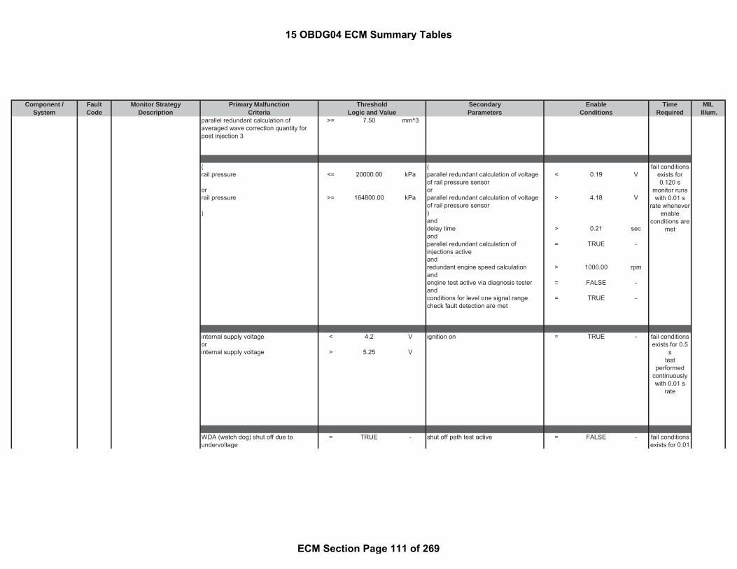
Component / Fault Monitor Strategy Primary Malfunction Secondary Time MILSystem Code Description Criteria Parameters Required Illum.
Threshold EnableLogic and Value Conditions
parallel redundant calculation ofaveraged wave correction quantity forpost injection 3
>= 7.50 mm^3
( (rail pressure <= 20000.00 kPa parallel redundant calculation of voltage
of rail pressure sensor< 0.19 V
or orrail pressure >= 164800.00 kPa parallel redundant calculation of voltage
of rail pressure sensor> 4.18 V
) )anddelay time > 0.21 secandparallel redundant calculation ofinjections active
= TRUE -
andredundant engine speed calculation > 1000.00 rpmandengine test active via diagnosis tester = FALSE -andconditions for level one signal rangecheck fault detection are met
= TRUE -
internal supply voltage < 4.2 V ignition on = TRUE -orinternal supply voltage > 5.25 V
WDA (watch dog) shut off due toundervoltage
= TRUE - shut off path test active = FALSE -
fail conditionsexists for 0.5
stest
performedcontinuouslywith 0.01 s
rate
fail conditionsexists for 0.01
fail conditionsexists for0.120 s
monitor runswith 0.01 s
rate wheneverenable
conditions aremet
15 OBDG04 ECM Summary Tables
ECM Section Page 111 of 269

Component / Fault Monitor Strategy Primary Malfunction Secondary Time MILSystem Code Description Criteria Parameters Required Illum.
Threshold EnableLogic and Value Conditions
means andinternal supply voltage < 4.2 V battery voltage > 8.00 V
fortime > 0.01 sec
andWDA (watch dog) line active = TRUE -
WDA (watch dog) shut off due toovervoltage
= TRUE - shut off path test active = FALSE -
means andinternal supply voltage > 5.25 V WDA (watch dog) line active = TRUE -
WDA (watch dog) shut off due to internalsecurity error
= TRUE - shut off path test active = FALSE -
andWDA (watch dog) line active = TRUE -
smonitor runswith 0.01 s
rate wheneverenable
conditions aremet
fail conditionsexists for 0.01
smonitor runswith 0.01 s
rate wheneverenable
conditions aremet
fail conditionsexists for 0.01
smonitor runswith 0.01 s
rate wheneverenable
conditions aremet
15 OBDG04 ECM Summary Tables
ECM Section Page 112 of 269

Component / Fault Monitor Strategy Primary Malfunction Secondary Time MILSystem Code Description Criteria Parameters Required Illum.
Threshold EnableLogic and Value Conditions
WDA (watch dog) shut off because ofcorrupt question-and-answercommunication
= TRUE - ignition on = TRUE -
andWDA (watch dog) line active = TRUE -andshut off path test active = FALSE -
the actual response time from processoris not equal to the requested response-time
= TRUE - ignition on = TRUE -
andNO Pending or Confirmed DTCs: = see sheet inhibit
tables-
redundant, independent algorithm forplausibility fault of accelerator pedalsignal for safety reasons:
ignition on = TRUE -
Path 1: and|(maximum (a) (b)) - 2 * (maximum (c)(b))|
> 0.29 V engine test active via diagnosis tester = FALSE -
with and(a) voltage accelerator pedal 1 = measured
parameter- Input signal fault present = FALSE -
and with and(b) lower limit for accelerator pedalvoltage
= 0.85 V ADC fault present = FALSE -
fail conditionsexists for 0.01
smonitor runswith 0.01 s
rate wheneverenable
conditions aremet
fail conditionsexists formore than
0.08 smonitor runsat least twiceevery 0.08 s
rate wheneverenable
conditions aremet
fail conditionsexists for 0.29
smonitor runswith 0.04 s
rate wheneverenable
conditions aremet
15 OBDG04 ECM Summary Tables
ECM Section Page 113 of 269

Component / Fault Monitor Strategy Primary Malfunction Secondary Time MILSystem Code Description Criteria Parameters Required Illum.
Threshold EnableLogic and Value Conditions
and with(c) voltage accelerator pedal 2 = measured
parameter-
and(voltage accelerator pedal 1 > 1.54 Vorvoltage accelerator pedal 2 > 1.54 V)orPath 2:|(maximum (a) (b)) - 2 * (maximum (c)(b))|
> 0.41 V
with(a) voltage accelerator pedal 1 = measured
parameter-
and with(b) lower limit for accelerator pedalvoltage
0.85 V
and with(c) voltage accelerator pedal 2 = measured
parameter-
and(voltage accelerator pedal 1 <= 1.54 Vorvoltage accelerator pedal 2 <= 1.54 V)
Error during positive test = TRUE - ignition on = TRUE -processor internal and
NO Pending or Confirmed DTCs: = see sheet inhibittables
-
fail conditionsexists formore than
0.08 smonitor runsat least twiceevery 0.08 s
rate wheneverenable
conditions aremet
15 OBDG04 ECM Summary Tables
ECM Section Page 114 of 269
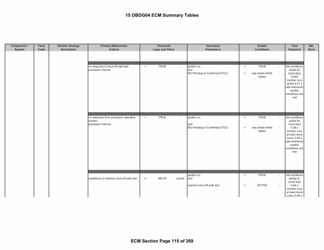
Component / Fault Monitor Strategy Primary Malfunction Secondary Time MILSystem Code Description Criteria Parameters Required Illum.
Threshold EnableLogic and Value Conditions
no response to shut-off path test = TRUE - ignition on = TRUE -processor internal and
NO Pending or Confirmed DTCs: = see sheet inhibittables
-
no response from processor operativesystem
= TRUE - ignition on = TRUE -
processor internal andNO Pending or Confirmed DTCs: = see sheet inhibit
tables-
ignition on = TRUE -repetitions of injection shut-off path test >= 485.00 counts and
injection shut-off path test = ACTIVE -
fail conditionsexists formore than
0.08 smonitor runsat least twiceevery 0.08 s
rate wheneverenable
conditions aremet
fail conditionsexists formore than
0.64 smonitor runsat least twiceevery 0.08 s
fail conditionsexists formore than
0.485monitor runsat the 0.01 s
rate wheneverenable
conditions aremet
15 OBDG04 ECM Summary Tables
ECM Section Page 115 of 269

Component / Fault Monitor Strategy Primary Malfunction Secondary Time MILSystem Code Description Criteria Parameters Required Illum.
Threshold EnableLogic and Value Conditions
prevention of the execution of the shut-off path test
= TRUE - ignition on = TRUE -
andinjection shut-off path test = ACTIVE -
too few bytes received by monitoringmodule from CPU
= TRUE - ignition on = TRUE -
meansbytes received by monitoring modulefrom CPU as response
< 4 Bytes
yrate whenever
enableconditions are
met
fail conditionsexists for 0.08
smonitor runsat least twiceevery 0.08 s
rate wheneverenable
conditions aremet
fail conditionsexists for
more than 0.4s
monitor runsat least twiceevery 0.08 s
rate wheneverenable
conditions aremet
15 OBDG04 ECM Summary Tables
ECM Section Page 116 of 269

Component / Fault Monitor Strategy Primary Malfunction Secondary Time MILSystem Code Description Criteria Parameters Required Illum.
Threshold EnableLogic and Value Conditions
ECM detects interruption in the SPIcommunication
= TRUE - ignition on = TRUE -
processor internal
ECM detects plausibility error of thecommunication between controller andthe monitoring module (2 processors inECU)
= TRUE - ignition on = TRUE -
processor internal
piezo injector actuator internal feedbackvoltage
< 0.00 V main injection = ACTIVE
orpiezo injector actuator internal feedbackvoltage
> 3.30 V
fail conditionsexists formore than
0.08 smonitor runsat least twiceevery 0.08 s
rate wheneverenable
conditions aremet
fail conditionsexists for
more than 0.2s
monitor runsat least twiceevery 0.08 s
rate wheneverenable
conditions aremet
fail conditionsexists for
more than 0.1s
monitor runs
15 OBDG04 ECM Summary Tables
ECM Section Page 117 of 269

Component / Fault Monitor Strategy Primary Malfunction Secondary Time MILSystem Code Description Criteria Parameters Required Illum.
Threshold EnableLogic and Value Conditions
Path 1: injection cut off demand from ECMinternal monitoring
= TRUE
engine speed > 1500.00 rpmorPath 2:engine speed > 1600.00 rpm
security torque limitation request due toimplausible air system control requests
= TRUE - ignition on = TRUE -
security torque limitation request due toimplausible rail pressure request
= TRUE - ignition on = TRUE - fail conditionsexists formore than267 events
testperformed
with 0.01 srate whenever
enableconditions are
met
fail conditionsexists for 0.02
stest
performedcontinuouslywith 0.02 s
fail conditionsexists formore than267 events
testperformed
continuouslywith 0.01 s
15 OBDG04 ECM Summary Tables
ECM Section Page 118 of 269

Component / Fault Monitor Strategy Primary Malfunction Secondary Time MILSystem Code Description Criteria Parameters Required Illum.
Threshold EnableLogic and Value Conditions
security torque limitation request due toimplausible quantity setpoint controlrequests
= TRUE - ignition on = TRUE -
indicated torque > (a) + (b) + (c) +(d)
- Engine Running = TRUE -
with and(a) modeled inner engine torque = calculated
parameter- basic enable conditions met: = see sheet enable
tables-
and with(b) torque tolerance offset = 11.72 %and with(c) torque of engine speed controller = calculated
parameter-
and with(d) torque of surge damper control = calculated
parameter-
voltage of charging switch > 210.00 V ECM is in startup before injections arereleased
= TRUE
orvoltage of charging switch if buffer of abank is not charged completely, or not atall
> 210.00 V
continuouslywith 0.01 s
fail conditionsexists formore than267 events
testperformed
continuouslywith 0.01 s
fail conditionsexists formore than
0.28 smonitor runswith 0.04 s
rate wheneverenable
conditions aremet
fail conditionsexists for
more than 4events
monitor runswith 0.01 s
rate whenever
15 OBDG04 ECM Summary Tables
ECM Section Page 119 of 269

Component / Fault Monitor Strategy Primary Malfunction Secondary Time MILSystem Code Description Criteria Parameters Required Illum.
Threshold EnableLogic and Value Conditions
error at startup of DC/DC converter ofone bank
= TRUE - ignition on = TRUE -
andDC/DC converter is in startup = TRUE -
DC/DC converter cannot be switched off. = TRUE - ignition on = TRUE -
ECM Electronic out-put drivercircuitry determines if shortcircuit faults exist on injectorcharging bank #0.
Path 1: Engine pre drive = TRUE -
Voltage high of injector bank #0 chargingswitch in case of loaded buffer capacitor
> 210.00 V
orPath 2:Voltage high of injector bank #0 chargingswitch in case of not loaded buffercapacitor
> 210.00 V
enableconditions are
met
fail conditionsexists for 0.01
smonitor runswith 0.01 s
rate wheneverenable
conditions aremet
fail conditionsexists formore than
0.04 smonitor runswith 0.01 s
rate wheneverenable
conditions aremet
15 OBDG04 ECM Summary Tables
ECM Section Page 120 of 269

Component / Fault Monitor Strategy Primary Malfunction Secondary Time MILSystem Code Description Criteria Parameters Required Illum.
Threshold EnableLogic and Value Conditions
ECM Electronic out-put drivercircuitry determines if shortcircuit faults exist on injectorcharging bank #1.
Path 1: Engine pre drive = TRUE -
Voltage high of injector bank #1 chargingswitch in case of loaded buffer capacitor
> 210.00 V
orPath 2:Voltage high of injector bank #1charging switch in case of not loadedbuffer capacitor
> 210.00 V
Control ModuleAnalog to DigitalPerformance
P060B Electronic ECM circuitrydetermines if ADC is correctlyconverting signals within thecorrect time periods.
time for calibration of ADC >= 0.30 sec ignition on = TRUE - A
voltage at ADC test voltage input < 4.73 V ignition on = TRUE -orvoltage at ADC test voltage input > 4.83 V
fail conditionsexists for 0.01
stest
performedcontinuously
0.01 s
fail conditionsexists for atleast 0.15 s
testperformed
continuously0.01 s
fail conditionsexists formore than
0.04 smonitor runswith 0.01 s
rate wheneverenable
conditions aremet
15 OBDG04 ECM Summary Tables
ECM Section Page 121 of 269
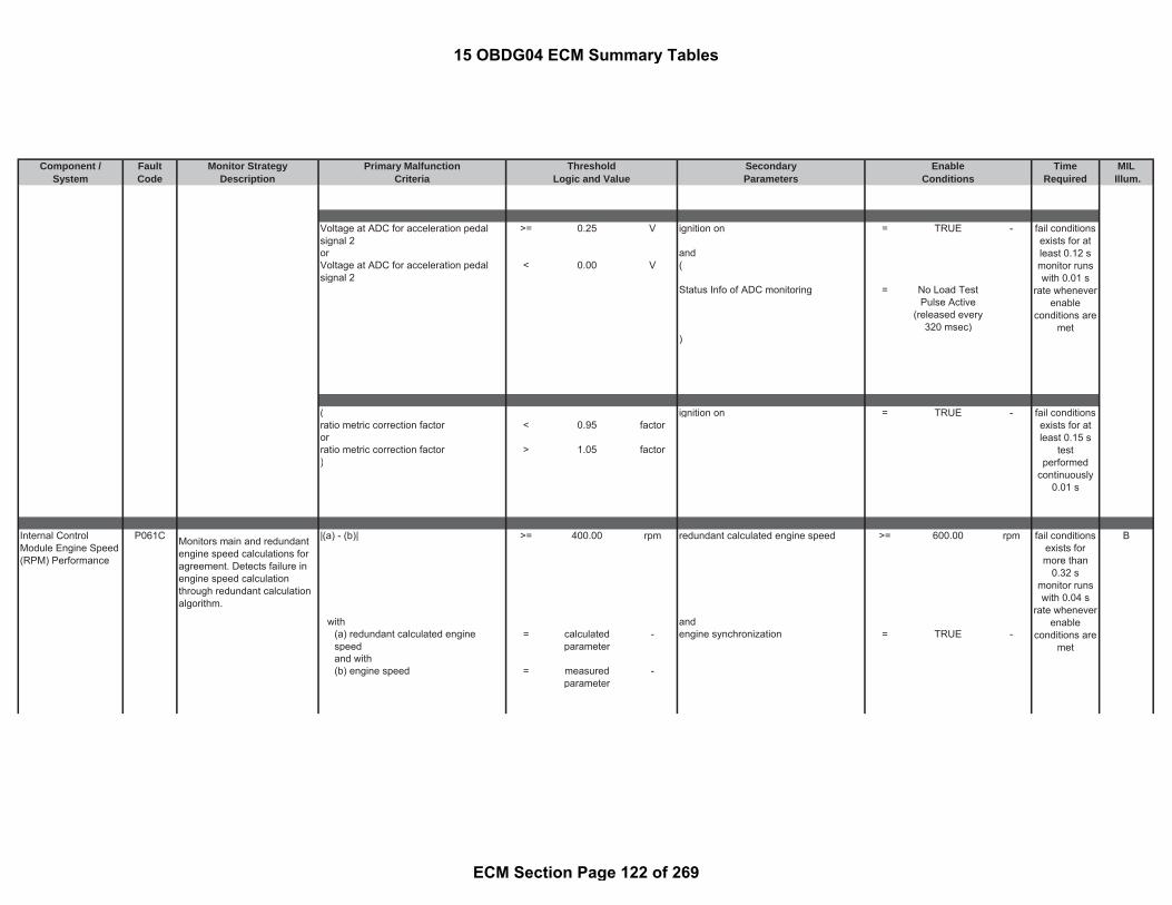
Component / Fault Monitor Strategy Primary Malfunction Secondary Time MILSystem Code Description Criteria Parameters Required Illum.
Threshold EnableLogic and Value Conditions
Voltage at ADC for acceleration pedalsignal 2
>= 0.25 V ignition on = TRUE -
or andVoltage at ADC for acceleration pedalsignal 2
< 0.00 V (
Status Info of ADC monitoring = No Load TestPulse Active
(released every320 msec)
)
( ignition on = TRUE -ratio metric correction factor < 0.95 factororratio metric correction factor > 1.05 factor)
Internal ControlModule Engine Speed(RPM) Performance
P061C Monitors main and redundantengine speed calculations foragreement. Detects failure inengine speed calculationthrough redundant calculationalgorithm.
|(a) - (b)| >= 400.00 rpm redundant calculated engine speed >= 600.00 rpm B
with and(a) redundant calculated enginespeed
= calculatedparameter
- engine synchronization = TRUE -
and with(b) engine speed = measured
parameter-
fail conditionsexists for atleast 0.12 smonitor runswith 0.01 s
rate wheneverenable
conditions aremet
fail conditionsexists for atleast 0.15 s
testperformed
continuously0.01 s
fail conditionsexists formore than
0.32 smonitor runswith 0.04 s
rate wheneverenable
conditions aremet
15 OBDG04 ECM Summary Tables
ECM Section Page 122 of 269
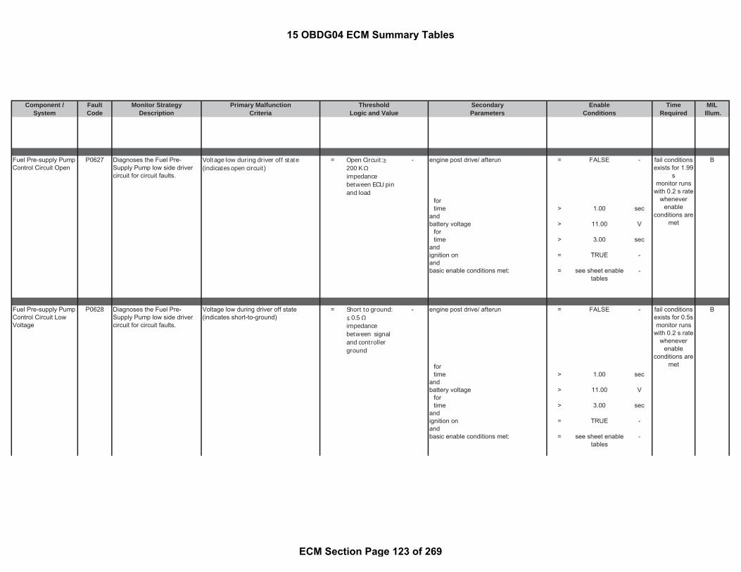
Component / Fault Monitor Strategy Primary Malfunction Secondary Time MILSystem Code Description Criteria Parameters Required Illum.
Threshold EnableLogic and Value Conditions
Fuel Pre-supply PumpControl Circuit Open
P0627 Diagnoses the Fuel Pre-Supply Pump low side drivercircuit for circuit faults.
Voltage low during driver off state(indicates open circuit)
= Open Circuit:200 K impedancebetween ECU pinand load
- engine post drive/ afterun = FALSE - B
fortime > 1.00 sec
andbattery voltage > 11.00 V
fortime > 3.00 sec
andignition on = TRUE -andbasic enable conditions met: = see sheet enable
tables-
Fuel Pre-supply PumpControl Circuit LowVoltage
P0628 Diagnoses the Fuel Pre-Supply Pump low side drivercircuit for circuit faults.
Voltage low during driver off state(indicates short-to-ground)
= Short to ground: 0.5
impedancebetween signaland controllerground
- engine post drive/ afterun = FALSE - B
fortime > 1.00 sec
andbattery voltage > 11.00 V
fortime > 3.00 sec
andignition on = TRUE -andbasic enable conditions met: = see sheet enable
tables-
fail conditionsexists for 0.5smonitor runs
with 0.2 s ratewhenever
enableconditions are
met
fail conditionsexists for 1.99
smonitor runs
with 0.2 s ratewhenever
enableconditions are
met
15 OBDG04 ECM Summary Tables
ECM Section Page 123 of 269

Component / Fault Monitor Strategy Primary Malfunction Secondary Time MILSystem Code Description Criteria Parameters Required Illum.
Threshold EnableLogic and Value Conditions
Fuel Pre-supply PumpControl Circuit HighVoltage
P0629 Diagnoses the Fuel Pre-Supply Pump low side drivercircuit for circuit faults.
Voltage high during driver on state(indicates short to power)
= Short to power: ≤ 0.5 Ωimpedancebetween signaland controllerpower
- engine post drive/ afterun = FALSE - B
fortime > 1.00 sec
andbattery voltage > 11.00 V
fortime > 3.00 sec
andignition on = TRUE -andbasic enable conditions met: = see sheet enable
tables-
Control Module LongTerm MemoryPerformance
P062F Each data block of memory isread for a check sum error andflags if a fault is found.
EEPROM sector reports faults regarding: ignition on = TRUE - A
unable to erase or change wholeEEPROM sector
= TRUE - and
or basic enable conditions met: = see sheet enabletables
-
read order is not successfullyaccomplished for more than amount ofblocks
= 3 counts
oramount of write errors in current block = 3 counts
Sensor ReferenceVoltage "A"Circuit/Open
P0641 Sensor supply voltage 1circuitry determines if faultsrelated to maintaining thesupply voltage level exists.
Reference supply voltage 1 ≤ 4.70 V Ignition on = TRUE - A
fail conditionsexists for 0.27
smonitor runs
with 0.2 s ratewhenever
enableconditions are
met
fail conditionsexists for 0.01
stest
performedcontinuouslyat the 0.01 s
rate
fail conditionsexists for 0.1
stest
15 OBDG04 ECM Summary Tables
ECM Section Page 124 of 269

Component / Fault Monitor Strategy Primary Malfunction Secondary Time MILSystem Code Description Criteria Parameters Required Illum.
Threshold EnableLogic and Value Conditions
or andReference supply voltage 1 ≥ 5.30 V basic enable conditions met: = TRUE -
Sensor ReferenceVoltage "B"Circuit/Open
P0651 Sensor supply voltage 2circuitry determines if faultsrelated to maintaining thesupply voltage level exists.
Reference supply voltage 2 ≤ 4.70 V Ignition on = TRUE - A
or andReference supply voltage 2 ≥ 5.30 V basic enable conditions met: = TRUE -
Sensor ReferenceVoltage "C"Circuit/Open
P0697 Sensor supply voltage 3circuitry determines if faultsrelated to maintaining thesupply voltage level exists.
Reference supply voltage 3 ≤ 4.70 V Ignition on = TRUE - A
or andReference supply voltage 3 ≥ 5.30 V basic enable conditions met: = TRUE -
Internal ControlModule O2 SensorProcessorPerformance Bank 1
P064D A/F sensor O2 signal monitorbased on comparison tointernal ECM circuit
Filtered A/F sensor circuit output withreference to internal ECM calibrationresistor
>= 0.20 V following conditions met for time: >= 0.26 sec B
within time period = 0.10 sec Common conditions:Engine is running = TRUE -
for time > 8.00 secOperation point 1:
fault exists formore than 6sec; monitorruns at 0.1 swhen enable
conditions aremet
performedcontinuously0.01s rate
fail conditionsexists for 0.1
stest
performedcontinuously0.01s rate
fail conditionsexists for 0.1
stest
performedcontinuously0.01s rate
15 OBDG04 ECM Summary Tables
ECM Section Page 125 of 269

Component / Fault Monitor Strategy Primary Malfunction Secondary Time MILSystem Code Description Criteria Parameters Required Illum.
Threshold EnableLogic and Value Conditions
(Injection quantity >= 4.00 mm^3/r
evInjection quantity =< 180.00 mm^3/r
evEngine speed >= 500.00 rpmEngine speed =< 4500.00 rpm)
orOperation point 2:
(Injection quantity >= 60.00 mm^3/r
evInjection quantity =< 180.00 mm^3/r
evEngine speed >= 3000.00 rpmEngine speed =< 4500.00 rpm)
Battery voltage > 11.00 VDPF regeneration is not active = FALSE -
for time > 0.50 secA/F sensor error status bit (seeparameter definition table)
= FALSE -
NO Pending or Confirmed DTCs: = see sheet inhibittables
-
basic enable conditions met: = see sheet enabletables
-
A/F sensor O2 signal monitorbased on comparison tointernal ECM circuit
Filtered A/F sensor circuit output withreference to internal ECM calibrationresistor
=< -0.20 V following conditions met for time: >= 0.26 sec
within time period = 0.10 sec Common conditions:Engine is running = TRUE -
for time > 8.00 secOperation point 1:
(Injection quantity >= 4.00 mm^3/r
evInjection quantity =< 180.00 mm^3/r
ev
fault exists formore than600 sec;
monitor runsat 0.1 s when
enableconditions are
met
15 OBDG04 ECM Summary Tables
ECM Section Page 126 of 269

Component / Fault Monitor Strategy Primary Malfunction Secondary Time MILSystem Code Description Criteria Parameters Required Illum.
Threshold EnableLogic and Value Conditions
Engine speed >= 500.00 rpmEngine speed =< 4500.00 rpm)
orOperation point 2:
(Injection quantity >= 60.00 mm^3/r
evInjection quantity =< 180.00 mm^3/r
evEngine speed >= 3000.00 rpmEngine speed =< 4500.00 rpm)
Battery voltage > 11.00 VDPF regeneration is not active = FALSE -
for time > 0.50 secA/F sensor error status bit (seeparameter definition table)
= FALSE -
NO Pending or Confirmed DTCs: = see sheet inhibittables
-
basic enable conditions met: = see sheet enabletables
-
A/F sensor resistancecomparison to internal ECMcalibration resistance
Filtered difference between Internalresistance raw value and internalresistance reference value
>= 0.20 V following conditions met for time: >= 0.26 sec
within time = 0.10 sec Common conditions:Engine is running = TRUE -
for time > 8.00 secOperation point 1:
(Injection quantity >= 4.00 mm^3/r
evInjection quantity =< 180.00 mm^3/r
evEngine speed >= 500.00 rpmEngine speed =< 4500.00 rpm)
orOperation point 2:
(
fault exists formore than600 sec;
monitor runsat 0.1 s when
enableconditions are
met
15 OBDG04 ECM Summary Tables
ECM Section Page 127 of 269

Component / Fault Monitor Strategy Primary Malfunction Secondary Time MILSystem Code Description Criteria Parameters Required Illum.
Threshold EnableLogic and Value Conditions
Injection quantity >= 60.00 mm^3/rev
Injection quantity =< 180.00 mm^3/rev
Engine speed >= 3000.00 rpmEngine speed =< 4500.00 rpm)
Battery voltage > 11.00 VDPF regeneration is not active = FALSE -
for time > 0.50 secA/F sensor error status bit (seeparameter definition table)
= FALSE -
NO Pending or Confirmed DTCs: = see sheet inhibittables
-
basic enable conditions met: = see sheet enabletables
-
A/F sensor resistancecomparison to internal ECMcalibration resistance
Filtered difference between Internalresistance raw value and internalresistance reference value
=< -0.20 V following conditions met for time: >= 0.26 sec
within time = 0.10 sec Common conditions:Engine is running = TRUE -
for time > 8.00 secOperation point 1:
(Injection quantity >= 4.00 mm^3/r
evInjection quantity =< 180.00 mm^3/r
evEngine speed >= 500.00 rpmEngine speed =< 4500.00 rpm)
orOperation point 2:
(Injection quantity >= 60.00 mm^3/r
evInjection quantity =< 180.00 mm^3/r
evEngine speed >= 3000.00 rpmEngine speed =< 4500.00 rpm
fault exists formore than600 sec;
monitor runsat 0.1 s when
enableconditions are
met
15 OBDG04 ECM Summary Tables
ECM Section Page 128 of 269

Component / Fault Monitor Strategy Primary Malfunction Secondary Time MILSystem Code Description Criteria Parameters Required Illum.
Threshold EnableLogic and Value Conditions
)Battery voltage > 11.00 VDPF regeneration is not active = FALSE -
for time > 0.50 secA/F sensor error status bit (seeparameter definition table)
= FALSE -
NO Pending or Confirmed DTCs: = see sheet inhibittables
-
basic enable conditions met: = see sheet enabletables
-
A/F sensor internal ECM SPIcontrol monitoring
Initialization register value of SPI chip isdifferent from the value written into SPIchip in previous cycle
= TRUE - Ignition on = TRUE -
NO Pending or Confirmed DTCs: = see sheet inhibittables
-
basic enable conditions met: = see sheet enabletables
-
Malfunction IndicatorLamp (MIL) ControlCircuit
P0650 Diagnoses the MalfunctionIndicator Lamp (MIL) low sidedriver circuit for circuit faults.
Voltage low during driver off state(indicates open circuit)
= Open Circuit:≥200 K Ωimpedancebetween ECU pinand load
- circuit active at low current = TRUE - A (no MIL)
andignition on = TRUE -andECU Initialization tasks in progress = FALSE -
fortime > 0.10 sec
andECU Shutdown tasks in progress = FALSE -
fortime > 1.00 sec
andBattery voltage > 10.50 V
fortime > 3.00 sec
fault exists formore than 0.1sec; monitorruns at 0.1 swhen enable
conditions aremet
fail conditionsexists for 2 smonitor runswith 0.01 s
rate wheneverenable
conditions aremet
15 OBDG04 ECM Summary Tables
ECM Section Page 129 of 269

Component / Fault Monitor Strategy Primary Malfunction Secondary Time MILSystem Code Description Criteria Parameters Required Illum.
Threshold EnableLogic and Value Conditions
andbasic enable conditions met: = see sheet enable
tables-
Fan 1 Control CircuitLow
P0691 Diagnoses the Cooling Fanlow side driver circuit for circuitfaults.
Voltage low during driver off state(indicates short-to-ground)
= Short to ground:≤ 0.5 Ωimpedancebetween signaland controllerground
- battery voltage > 11.00 V B
fortime > 3.00 sec
andstarter is active cranking = FALSE
fortime > 3.00 sec
andignition on = TRUE -andbasic enable conditions met: = see sheet enable
tables-
andNO Pending or Confirmed DTCs: = see sheet inhibit
tables-
Fan 1 Control CircuitHigh
P0692 Diagnoses the Cooling Fanlow side driver circuit for circuitfaults.
Voltage high during driver on state(indicates short to power)
= Short to power: ≤ 0.5 Ωimpedancebetween signaland controllerpower
- battery voltage > 11.00 V B
fortime > 3.00 sec
andstarter is active cranking = FALSE
fortime > 3.00 sec
fail conditionsexists for 3 s
testperformed
continuously0.02 s rate
fail conditionsexists for 1 s
testperformed
continuously0.02 s rate
15 OBDG04 ECM Summary Tables
ECM Section Page 130 of 269

Component / Fault Monitor Strategy Primary Malfunction Secondary Time MILSystem Code Description Criteria Parameters Required Illum.
Threshold EnableLogic and Value Conditions
andignition on = TRUE -andbasic enable conditions met: = see sheet enable
tables-
andNO Pending or Confirmed DTCs: = see sheet inhibit
tables-
Chassis ControlModule 1 RequestedMIL Illumination
P26C8 Monitors Serial DataCommunication for requestfrom Fuel Pump ControlModule to illuminate the MIL.
serial data communication from the FuelPump Control Module indicates the FuelPump Control Module has requested aMIL
= TRUE - ignition on = TRUE - B (No MIL)
Fuel Pump Control Modulecontrols the active grilleshutters on the vehicle
for
time > 3.00 secandnew message is received via CAN = TRUE -andbasic enable conditions met: = see sheet enable
tables-
andNO Pending or Confirmed DTCs: = see sheet inhibit
tables-
Engine Oil PressureControl Circuit/Open
P06DA Detects an open circuitcondition of the oil pumppressure selection switchcontrol circuit
The ECM detects that the commandedstate of the driver and the actual state ofthe control circuit do not match
= Open circuit:≥ 200 kΩimpedancebetween ECU pinand load
- ignition is on or running = TRUE - C
andNO Pending or Confirmed DTCs: = see sheet inhibit
tables-
andbasic enable conditions are met: = see sheet enable
tables-
fail conditionsexists for 1 smonitor runsonce per tripwith 0.25 s
rate wheneverenable
conditions aremet
fail conditionsexists for 5 s
testperformed
continuously0.02 s
15 OBDG04 ECM Summary Tables
ECM Section Page 131 of 269

Component / Fault Monitor Strategy Primary Malfunction Secondary Time MILSystem Code Description Criteria Parameters Required Illum.
Threshold EnableLogic and Value Conditions
Engine Oil PressureControl Circuit Low
P06DB Detects a short-to-groundcircuit condition of the oil pumppressure selection switchcontrol circuit
The ECM detects that the commandedstate of the driver and the actual state ofthe control circuit do not match
= Short-to-ground: ≤ 0.5 Ωimpedancebetween signaland controllerground
- ignition is on or running = TRUE - C
andNO Pending or Confirmed DTCs: = see sheet inhibit
tables-
andbasic enable conditions are met: = see sheet enable
tables-
Engine Oil PressureControl Circuit High
P06DC Detects a short-to-batterycircuit condition of the oil pumppressure selection switchcontrol circuit
The ECM detects that the commandedstate of the driver and the actual state ofthe control circuit do not match
= Short-to-power:≤ 0.5 Ωimpedancebetween signaland controllerpower
- ignition is on or running = TRUE - C
andNO Pending or Confirmed DTCs: = see sheet inhibit
tables-
andbasic enable conditions are met: = see sheet enable
tables-
Transmission ControlModule (TCM)Requested MILIllumination
P0700 Monitors Serial DataCommunication for requestfrom TCM to illuminate theMIL.
serial data communication from the TCMindicates the TCM has requested a MIL
= TRUE - ignition on = TRUE - B (No MIL)
fortime > 3.00 sec
fail conditionsexists for 5 s
testperformed
continuously0.02 s
fail conditionsexists for 1 smonitor runsonce per tripwith 0.25 s
rate whenever
fail conditionsexists for 5 s
testperformed
continuously0.02 s
15 OBDG04 ECM Summary Tables
ECM Section Page 132 of 269

Component / Fault Monitor Strategy Primary Malfunction Secondary Time MILSystem Code Description Criteria Parameters Required Illum.
Threshold EnableLogic and Value Conditions
andnew message is received via CAN = TRUE -andbasic enable conditions met: = see sheet enable
tables-
andNO Pending or Confirmed DTCs: = see sheet inhibit
tables-
Brake Switch "B"Circuit
P0703 Rolling counter and protectionvalue evaluation of messagereceived from Body ControlModule
number of messages with validationerrors
>= 3.00 counts ignition on = TRUE - C
in the last number of messages (slidingwindow) received from body controlmodule
= 10.00 counts for time >= 3.00 sec
andbasic enable conditions met: = see sheet enable
tables-
andNO Pending or Confirmed DTCs: = see sheet inhibit
tables-
Park/Neutral Position(PNP) Switch CircuitHigh Voltage
P0851 Detects high voltage conditionon the PNP circuit bycomparing the ECM sensedinput to the broadcasted statefrom the TCM over GMLANserial data
ECM (on-board control unit) sensedposition based on PNP switch inputs toECM indicates park or neutral and theGMLAN message from the TCMdisagrees
= TRUE - ( B
battery voltage >= 11.00 Vandbattery voltage <= 655.34 V)andengine speed >= 800.00 rpmandvehicle speed >= 14.92 mphand
enableconditions are
met
fail conditionsexists for0.015 s
testperformed
continuously0.005 s rate
fail conditionsexist for more
than 3000events
monitor runswith 0.01 s
rate wheneverenable
conditions aremet
15 OBDG04 ECM Summary Tables
ECM Section Page 133 of 269
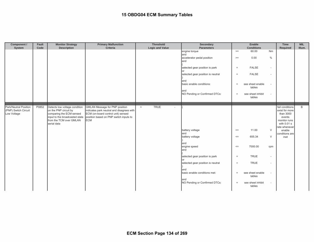
Component / Fault Monitor Strategy Primary Malfunction Secondary Time MILSystem Code Description Criteria Parameters Required Illum.
Threshold EnableLogic and Value Conditions
engine torque >= 60.00 Nmandaccelerator pedal position >= 0.00 %and(selected gear position is park = FALSE -orselected gear position is neutral = FALSE -)andbasic enable conditions: = see sheet enable
tables-
andNO Pending or Confirmed DTCs: = see sheet inhibit
tables-
Park/Neutral Position(PNP) Switch CircuitLow Voltage
P0852 Detects low voltage conditionon the PNP circuit bycomparing the ECM sensedinput to the broadcasted statefrom the TCM over GMLANserial data
GMLAN Message for PNP positionindicates park neutral and disagrees withECM (on-board control unit) sensedposition based on PNP switch inputs toECM
= TRUE - ( B
battery voltage >= 11.00 Vandbattery voltage <= 655.34 V)andengine speed <= 7000.00 rpmand(selected gear position is park = TRUE -orselected gear position is neutral = TRUE -)andbasic enable conditions met: = see sheet enable
tables-
andNO Pending or Confirmed DTCs: = see sheet inhibit
tables-
fail conditionsexist for more
than 3000events
monitor runswith 0.01 s
rate wheneverenable
conditions aremet
15 OBDG04 ECM Summary Tables
ECM Section Page 134 of 269

Component / Fault Monitor Strategy Primary Malfunction Secondary Time MILSystem Code Description Criteria Parameters Required Illum.
Threshold EnableLogic and Value Conditions
Traction Control InputSignal
P0856 Detects a failure when acertain number of TractionControl System torque requestmessages within a definedmessage group checksum orrolling count values areincorrect
number of messages with validationerrors
>= 8.00 counts ignition on = TRUE - Special C
in the last number of messages (slidingwindow) received from traction controlsystem
= 10.00 counts for time >= 3.00 sec
andbasic enable conditions met: = see sheet enable
tables-
andNO Pending or Confirmed DTCs: = see sheet inhibit
tables-
Reductant Pump HighControl Circuit LowVoltage
P1043 Diagnoses the RuductantPump Motor high side drivercircuit for circuit faults.
Voltage low during driver on state(indicates short to ground)
= Short to ground: ≤ 0.5 Ωimpedancebetween signaland controllerground
- ignition on = TRUE - B
andECU Initialization tasks in progress = FALSE -
fortime > 0.10 sec
andBattery voltage > 10.50 V
fortime > 3.00 sec
andbasic enable conditions met: = see sheet enable
tables-
ANDNO Pending or Confirmed DTCs = see sheet inhibit
tables-
testperformed
continuously0.01 s rate
fail conditionsexists for 3 smonitor runswith 0.010 s
rate wheneverenable
conditions aremet
15 OBDG04 ECM Summary Tables
ECM Section Page 135 of 269

Component / Fault Monitor Strategy Primary Malfunction Secondary Time MILSystem Code Description Criteria Parameters Required Illum.
Threshold EnableLogic and Value Conditions
Reductant Pump HighControl Circuit HighVoltage
P1044 Diagnoses the RuductantPump Motor high side drivercircuit for circuit faults.
Voltage high during driver off state(indicates short to power )
= Short to power: ≤0.5 Ω impedancebetween signaland controllerpower
- ignition on = TRUE - B
andECU Initialization tasks in progress = FALSE -
fortime > 0.10 sec
andBattery voltage > 10.50 V
fortime > 3.00 sec
andbasic enable conditions met: = see sheet enable
tables-
ANDNO Pending or Confirmed DTCs = see sheet inhibit
tables-
Reductant PurgeValve High ControlCircuit High Voltage
P1046 Diagnoses the ReductantPurge Valve high side drivercircuit for circuit faults.
Voltage high during driver off state(indicates short to power )
= Short to power: ≤0.5 Ω impedancebetween signaland controllerpower
- ignition on = TRUE - B
andECU Initialization tasks in progress = FALSE -
fortime > 0.10 sec
andBattery voltage > 10.50 V
fortime > 3.00 sec
andbasic enable conditions met: = see sheet enable
tables-
AND
fail conditionsexists for 3 smonitor runswith 0.010 s
rate wheneverenable
conditions aremet
fail conditionsexists for 3 smonitor runswith 0.010 s
rate wheneverenable
conditions aremet
15 OBDG04 ECM Summary Tables
ECM Section Page 136 of 269
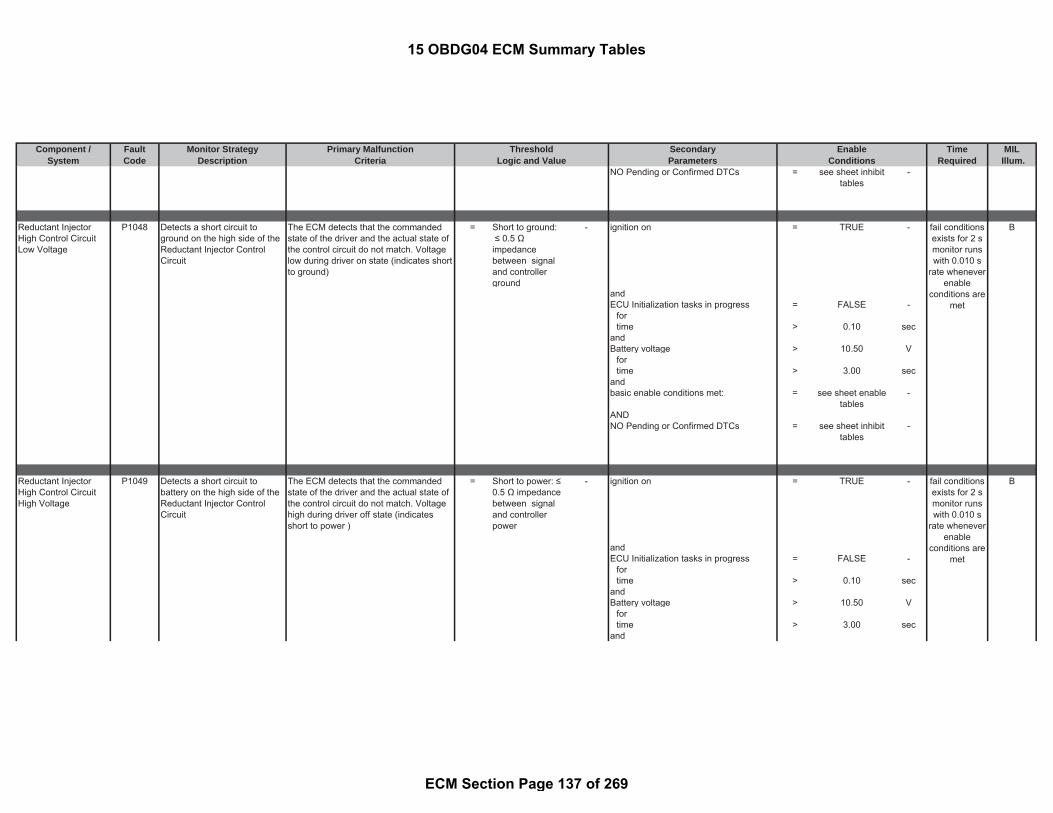
Component / Fault Monitor Strategy Primary Malfunction Secondary Time MILSystem Code Description Criteria Parameters Required Illum.
Threshold EnableLogic and Value Conditions
NO Pending or Confirmed DTCs = see sheet inhibittables
-
Reductant InjectorHigh Control CircuitLow Voltage
P1048 Detects a short circuit toground on the high side of theReductant Injector ControlCircuit
The ECM detects that the commandedstate of the driver and the actual state ofthe control circuit do not match. Voltagelow during driver on state (indicates shortto ground)
= Short to ground: ≤ 0.5 Ωimpedancebetween signaland controllerground
- ignition on = TRUE - B
andECU Initialization tasks in progress = FALSE -
fortime > 0.10 sec
andBattery voltage > 10.50 V
fortime > 3.00 sec
andbasic enable conditions met: = see sheet enable
tables-
ANDNO Pending or Confirmed DTCs = see sheet inhibit
tables-
Reductant InjectorHigh Control CircuitHigh Voltage
P1049 Detects a short circuit tobattery on the high side of theReductant Injector ControlCircuit
The ECM detects that the commandedstate of the driver and the actual state ofthe control circuit do not match. Voltagehigh during driver off state (indicatesshort to power )
= Short to power: ≤0.5 Ω impedancebetween signaland controllerpower
- ignition on = TRUE - B
andECU Initialization tasks in progress = FALSE -
fortime > 0.10 sec
andBattery voltage > 10.50 V
fortime > 3.00 sec
and
fail conditionsexists for 2 smonitor runswith 0.010 s
rate wheneverenable
conditions aremet
fail conditionsexists for 2 smonitor runswith 0.010 s
rate wheneverenable
conditions aremet
15 OBDG04 ECM Summary Tables
ECM Section Page 137 of 269

Component / Fault Monitor Strategy Primary Malfunction Secondary Time MILSystem Code Description Criteria Parameters Required Illum.
Threshold EnableLogic and Value Conditions
basic enable conditions met: = see sheet enabletables
-
ANDNO Pending or Confirmed DTCs = see sheet inhibit
tables-
Fuel Rail PressurePerformance
P1089 Measured rail pressure ischecked against desired railpressure to detect high railpressure conditions in fuel cut-off
rail pressure deviation from setpointcalculated as the absolute value ofdifference between desired and actualvalue
> 2500.00 kPa rail pressure control commanded duringinjection timing correction learning phase
= TRUE - B
andNO Pending or Confirmed DTCs limitingrail pressure set point
= see sheet inhibittables
-
for time > 2.00 secandbasic enable conditions met: = see sheet enable
tables-
Charge Air CoolerTemperature SensorPerformance
P10CF Detects a biased charge aircooler temperature sensordownstream or charge aircooler temperature sensorupstream by comparing therespective values at startup.
Path 1: minimum engine-off time >= 28800.00 sec B
andengine-off time is valid = TRUE
|(a) - (b)| (see Look-Up-Table #3) > 25 to 999 °C andwith ambient temperature > -60.04 °C
(a) captured charge air coolerdownstream temperature at start
= measuredparameter
- and
and with engine speed (see Look-Up-Table #81) > 850 to 1100 rpm
(b) captured charge air cooler upstreamtemperature at start
= measuredparameter
- for
time > 0.01 sec
fail conditionsexists for 720
crankrevolutions
monitor runswith 0.02 s
rate wheneverenable
conditions aremet
fail conditionsexists for 0.1
smonitor runsonce per trip
with 0.1 s ratewhenever
enableconditions are
met
15 OBDG04 ECM Summary Tables
ECM Section Page 138 of 269

Component / Fault Monitor Strategy Primary Malfunction Secondary Time MILSystem Code Description Criteria Parameters Required Illum.
Threshold EnableLogic and Value Conditions
andengine post drive/ afterun = FALSE -anddiagnostic performed in current dc = FALSE -andbasic enable conditions met: = see sheet enable
tables-
andNO Pending or Confirmed DTCs: = see sheet inhibit
tables-
Reductant InjectorTemperature -Exhaust GasTemperature 2Correlation
P10D0 |(a) - (b)| (see Look-Up-Table #80) > 30 to 3276.7 °C ignition on = TRUE - B
with and(a) dosing valve coil temperature = calculated
parameter°C state of selective catalytic reduction
system= STANDBY or NO
PRESSURECONTROL
-
and with and(b) oxidation catalyst downstreamtemperature
= measuredparameter
°C active heating phase for dosing valve = FALSE -
andvalve already activated within this drivingcycle
= FALSE -
andbattery voltage > 11.00 Vandambient temperature >= -60.04 °Candengine run time < 3.00 secandengine off time > 28800.00 secandurea pump motor output duty cycle = 0.00 %andMax [(a), (b)] - Min [(a), (b)] <= 15.00 K
where(a) ambient temperature = measured
parameter-
Detects an implausible SCRdosing valve coil temperatureby comparing the temperaturewith a reference temperature
fail conditionsexists for 0.1
smonitor with
0.1 s ratewhenever
enableconditions are
met
15 OBDG04 ECM Summary Tables
ECM Section Page 139 of 269

Component / Fault Monitor Strategy Primary Malfunction Secondary Time MILSystem Code Description Criteria Parameters Required Illum.
Threshold EnableLogic and Value Conditions
(b) oxidation catalyst downstreamtemperature
= measuredparameter
-
andurea dosing valve output duty cycle > 3.00 %andcoil current measurement is valid (e.g. nodosing valve errors present)
= TRUE -
andbasic enable conditions met: = see sheet enable
tables-
andNO Pending or Confirmed DTCs: = see sheet inhibit
tables-
O2 SensorPerformance - SignalHigh During ModerateLoad Sensor 1
P11A6 A/Fsensor signal monitoring inpart load mode, whichmonitors a deviation of the rawA/F sensor signal andcalculated sensor signal
difference between measured A/F sensorconcentration and filtered calculated A/Fconcentration -> refer to Column 1 in thetable (see Look-Up-Table #51)
> 0.04 to 0.07 - following conditions met for Integrated airmass:
> 80 g B
Note: Calculated A/F concentration iscalculated as a function of InjectionQuantity and Air Mass per cylinder(which is calculated on MAF sensorand EGR)
Engine speed ->refer to the Column 1in the table (see Look-Up-Table #47)
< 2700 to 4500 rpm
Injection quantity -> refer to the Column1 in the table (see Look-Up-Table #49)
> -1 to 16 mm^3/rev
Injection quantity -> refer to the Column1 in the table (see Look-Up-Table #48)
< 0.4 to 44 mm^3/rev
Air mass per cylinder ->refer to theColumn 1 in the table (see Look-Up-Table #46)
> 0.09 to 0.25 g/rev
Air mass per cylinder ->refer to theColumn 1 in the table (see Look-Up-Table #45)
< 0.253 to 0.45 g/.rev
DPF regeneration not active = TRUE -Post injection is not active (postinjection only active during cold startcatalyst heating or DPF regeneration)
= TRUE -
fail conditionsexists for 0.1
smonitor runswith 0.02 s
rate wheneverenable
conditions aremet
15 OBDG04 ECM Summary Tables
ECM Section Page 140 of 269

Component / Fault Monitor Strategy Primary Malfunction Secondary Time MILSystem Code Description Criteria Parameters Required Illum.
Threshold EnableLogic and Value Conditions
Temperature of A/F sensor (based onsensor internal resistance)
=< 805.96 °C
Temperature of A/F sensor (based onsensor internal resistance)
>= 823.96 °C
Absolute change in actual calculatedO2 concentration
< 0.02 -
for time >= 1.50 secFuel volume in fuel tank >= 0.00 LBattery voltage >= 11.00 VDecel Fuel Cut-Off (DFCO) = FALSE -NO Pending or Confirmed DTCs: = see sheet inhibit
tables-
basic enable conditions met: = see sheet enabletables
-
O2 SensorPerformance - SignalLow During ModerateLoad Bank 1 Sensor 1
P11A9 A/Fsensor signal monitoring inpart load mode, whichmonitors a deviation of the rawA/F sensor signal andcalculated sensor signal
difference between filtered calculatedA/F concentration and measured A/Fsensor concentration -> refer to Column1 in the table (see Look-Up-Table #50)
> 0.06 to 0.07 - following conditions met for Integrated airmass:
> 80 g B
Note: Calculated A/F concentration iscalculated as a function of InjectionQuantity and Air Mass per cylinder(which is calculated on MAF sensorand EGR)
Engine speed refer to the column 1(see Look-Up-Table #47)
< 2700 to 4500 rpm
Injection quantity -> refer to the Column1 in the table (see Look-Up-Table #49)
> -1 to 16 mm^3/rev
Injection quantity -> refer to the Column1 in the table (see Look-Up-Table #48)
< 0.4 to 44 mm^3/rev
Air mass per cylinder ->refer to theColumn 1 in the table (see Look-Up-Table #46)
> 0.09 to 0.25 g/rev
Air mass per cylinder ->refer to theColumn 1 in the table (see Look-Up-Table #45)
< 0.253 to 0.45 g/.rev
DPF regeneration not active = TRUE -Post injection is not active (postinjection only active during cold startcatalyst heating or DPF regeneration)
= TRUE -
fail conditionsexists for 0.1
smonitor runswith 0.02 s
rate wheneverenable
conditions aremet
15 OBDG04 ECM Summary Tables
ECM Section Page 141 of 269

Component / Fault Monitor Strategy Primary Malfunction Secondary Time MILSystem Code Description Criteria Parameters Required Illum.
Threshold EnableLogic and Value Conditions
Temperature of A/F sensor (based onsensor internal resistance)
>= 805.96 °C
Temperature of A/F sensor (based onsensor internal resistance)
<= 823.96 °C
Absolute change in actual calculatedO2 concentration
< 0.02 -
for time >= 1.50 secFuel volume in fuel tank >= 0.00 LBattery voltage >= 11.00 VDecel Fuel Cut-Off (DFCO) = FALSE -NO Pending or Confirmed DTCs: = see sheet inhibit
tables-
basic enable conditions met: = see sheet enabletables
-
NOx SensorPerformance - SignalHigh Bank 1 Sensor 1
P11CB Detects a high deviation of themeasured NOx sensorconcentration from themodeled NOx concentration
EWMA filtered delta high upstream NOxmonitor
< 0.00 factor Duration for averaging upstream NOxsensor signal and NOx model
>= 6.00 sec A
Threshold for high upstream NOxrationality check
= (a) * (b) * ( c ) *(d) * (e)
(a) Base threshold for high upstreamNOx rationality check (see Look-Up-Table #74)
= 0.410034 to1.400024
factor (
(b) correction factor dependent onNOx model
= 1 factor Status of NOx signal of upstream NOxsensor (please see the definition)
= TRUE -
(c) correction factor dependent onengine coolant temperature andtransmission gear
= 1 factor Normal Mode (Particulate FilterRegeneration not active)
= TRUE -
(d ) correction factor dependent onambient pressure (see Look-Up-Table#86)
= 1.0 to 1.4 factor for time 30.00 sec
(e) correction factor dependent onrelative humidity
= 1 factor ambient pressure >= 74.80 kPa
ambient pressure <= 106.00 kPaambient temperature >= -30.04 °Cambient temperature <= 79.96 °C(filtered modeled NOx concentrationpercent positive deviation
<= 0.120117 factor
fault exists formore than 1
event; monitorruns at 0.1 sonce per trip
15 OBDG04 ECM Summary Tables
ECM Section Page 142 of 269

Component / Fault Monitor Strategy Primary Malfunction Secondary Time MILSystem Code Description Criteria Parameters Required Illum.
Threshold EnableLogic and Value Conditions
filtered modeled NOx concentrationpercent positive deviation
>= 0.120117 factor
for time >= 2.00 sec)
for time > 2.00 sectime since start > 0.00 secengine coolant temperature >= 59.96 °Cengine coolant temperature <= 125.96 °CExhaust gas temperature range atUpstream NOx sensor (see Look-Up-Table #76)
>0 0 to 1 factor
Vehicle speed >= 12.43 mphVehicle speed <= 37.29 mph
Enable range for the plausibility checkof Upstream NOx sensor (see Look-Up-Table #70)
≠0 0 to 1 factor
for time > 1.00 secfiltered modeled NOx-concentrationupstream of the SCR
>= 110.00 ppm
filtered modeled NOx-concentrationupstream of the SCR
<= 600.00 ppm
for time > 0.10 sec
)Diagnostic has not completed this drivingcycle
= FALSE -
NO Pending or Confirmed DTCs: = see sheet inhibittables
-
basic enable conditions met: = see sheet enabletables
-
EWMA fast initialization mode:filter coefficient for fast initialization = 0.32 factornumber of high upstream NOx monitormeasurements for current driving cycleof fast initialization mode
>= 1.00 counts
number of high upstream NOx monitormeasurements for fast initializationmode
>= 2.00 counts
15 OBDG04 ECM Summary Tables
ECM Section Page 143 of 269

Component / Fault Monitor Strategy Primary Malfunction Secondary Time MILSystem Code Description Criteria Parameters Required Illum.
Threshold EnableLogic and Value Conditions
EWMA Rapid Response mode:EWMA filtered delta high upstreamNOx monitor
> 0.31 factor
(a) - (b) < 0.00 factor(a) threshold of high upstream NOxmonitor
= calculatedparameter
-
(b) measured value of high upstreamNOx monitor
= calculatedparameter
-
filter coefficient for Rapid Responsemode
= 0.38 factor
number of high upstream NOx monitormeasurements for current driving cycleof Rapid Response mode
>= 1.00
Total number of high upstream NOxmonitor measurements for RapidResponse mode
>= 6.00 counts
EWMA stabilized mode:filter coefficient for stabilized mode = 0.22 factornumber of high upstream NOx monitormeasurements for stabilized mode
= 1 counts
NOx SensorPerformance - SignalLow Bank 1 Sensor 1
P11CC Detects a low deviation of themeasured NOx sensorconcentration from themodeled NOx concentration
EWMA filtered delta low upstream NOxmonitor
< 0.00 factor Duration for averaging upstream NOxsensor signal and NOx model
>= 6.00 sec A
Threshold for low upstream NOxrationality check
= (a) * (b) * ( c ) *(d) * (e)
factor Status of NOx signal of upstream NOxsensor (please see the definition)
= TRUE -
(a) Base threshold for high upstreamNOx rationality check (see Look-Up-Table #75)
= -0.670044 to -0.52002
factor Normal Mode (Particulate FilterRegeneration not active)
= TRUE -
(b) correction factor dependent on NOxmodel
= 1 factor for time 30.00 sec
(c ) correction factor dependent onengine coolant temperature andtransmission gear
= 1 factor ambient pressure >= 74.80 kPa
fault exists formore than 1
event; monitorruns at 0.1 sonce per trip
15 OBDG04 ECM Summary Tables
ECM Section Page 144 of 269

Component / Fault Monitor Strategy Primary Malfunction Secondary Time MILSystem Code Description Criteria Parameters Required Illum.
Threshold EnableLogic and Value Conditions
(d ) correction factor dependent onambient pressure (see Look-Up-Table#87)
= 0.62 to 1.0 factor ambient pressure <= 106.00 kPa
(e) correction factor dependent onrelative humidity (see Look-Up-Table#69)
= 1.00 factor ambient temperature >= -30.04 °C
ambient temperature <= 79.96 °C((filtered modeled NOx concentrationpercent positive deviation
<= 0.120117 factor
filtered modeled NOx concentrationpercent negative deviation
>= 0.120117 factor
)for time >= 2.00 sec
for time > 2.00 sectime since start > 0.00 secCoolant engine down streamtemperature
>= 59.96 °C
Coolant engine down streamtemperature
<= 125.96 °C
Exhaust gas temperature range atUpstream NOx sensor (see Look-Up-Table #76)
>0 0 to 1 factor
Vehicle speed >= 12.43 mphVehicle speed <= 37.29 mph
for time > 1.00 secEnable range for the plausibility checkof Upstream NOx sensor (see Look-Up-Table #70)
≠0 0 to 1 factor
for time > 1.00 secfiltered modeled NOx-concentrationupstream of the SCR
>= 65.00 ppm
filtered modeled NOx-concentrationupstream of the SCR
<= 600.00 ppm
for time > 0.50 secDiagnostic has not completed this drivingcycle
= FALSE -
NO Pending or Confirmed DTCs: = see sheet inhibittables
-
basic enable conditions met: = see sheet enabletables
-
15 OBDG04 ECM Summary Tables
ECM Section Page 145 of 269

Component / Fault Monitor Strategy Primary Malfunction Secondary Time MILSystem Code Description Criteria Parameters Required Illum.
Threshold EnableLogic and Value Conditions
EWMA fast initialization mode:filter coefficient for fast initialization = 0.32 factornumber of low upstream NOx monitormeasurements for current driving cycleof fast initialization mode
>= 1.00 counts
number of low upstream NOx monitormeasurements for fast initializationmode
>= 2.00 counts
EWMA Rapid Response mode:EWMA filtered delta low upstream NOxmonitor
> 0.21 factor
(a) - (b) < 0.00 factor(a) measured value of low upstreamNOx monitor
= calculatedparameter
-
(b) threshold of low upstream NOxmonitor
= calculatedparameter
-
filter coefficient for Rapid Responsemode
= 0.38 factor
number of low upstream NOx monitormeasurements for current driving cycleof Rapid Response mode
>= 1.00
Total number of low upstream NOxmonitor measurements for RapidResponse mode
>= 6.00 counts
EWMA stabilized mode:filter coefficient for stabilized mode = 0.22 factornumber of low upstream NOx monitormeasurements for stabilized mode
= 1 counts
NOx Sensor OffsetLearning at Min Limit -Bank 1 Sensor 1
P11D3 Detects NOx offset value minof the upstream NoX Sensor
average NOx offset value < -90.00 ppm ( B
NOx sensor signal averaged over time = 1.00 sec battery voltage >= 11.00 V
andbattery voltage <= 655.34 Vand
fault exists formore than 2
DFCO events;monitor runs
at 0.02 swhen enableconditions are
met
15 OBDG04 ECM Summary Tables
ECM Section Page 146 of 269

Component / Fault Monitor Strategy Primary Malfunction Secondary Time MILSystem Code Description Criteria Parameters Required Illum.
Threshold EnableLogic and Value Conditions
Oxidation Catalyst upstreamtemperature
>= 99.96 °C
andOxidation Catalyst upstreamtemperature
<= 599.96 °C
andEngine running = TRUE -
for time > 20.00 secandUpstream NOx sensor dewpointachieved (please see the definition)
= TRUE -
)for time > 160 sec
following conditions for time: = 1.00 secEGR valve position >= 0.00 %EGR valve position <= 100.00 %NOx sensor measured lambda > 0.00 -
for time >= 0.50 secDFCO (Decel Fuel Cut-Off) active = TRUE -NOx sensor 1 ready status (seeparameter definition)
= TRUE -
Valid NOx signal from CAN is received(no NOx sensor communicationfailures)
= TRUE -
Engine Running (see parameterdefinition)
= TRUE -
for time > 20.00 secengine speed >= 1000.00 rpmengine speed <= 3500.00 rpmintegrated air mass flow (see Look-Up-Table #30)
> 100 to 500 g
NOx Sensor OffsetLearning at Max Limit -Bank 1 Sensor 1
P11D4 Detects NOx Offset value max.of the upstream NoX Sensor
average NOx offset value > 50.00 ppm ( B
NOx sensor signal averaged over time = 1.00 sec battery voltage >= 11.00 V
andbattery voltage <= 655.34 Vand
fault exists formore than 2
DFCO events;monitor runs
at 0.02 swhen enableconditions are
met
15 OBDG04 ECM Summary Tables
ECM Section Page 147 of 269

Component / Fault Monitor Strategy Primary Malfunction Secondary Time MILSystem Code Description Criteria Parameters Required Illum.
Threshold EnableLogic and Value Conditions
Oxidation Catalyst upstreamtemperature
>= 99.96 °C
andOxidation Catalyst upstreamtemperature
<= 599.96 °C
andEngine running = TRUE -
for time > 20.00 secandUpstream NOx sensor dewpointachieved (please see the definition)
= TRUE -
)for time > 160 sec
following conditions for time: = 1.00 secEGR valve position >= 0.00 %EGR valve position <= 100.00 %NOx sensor measured lambda > 0.00 -
for time >= 0.50 secDFCO (Decel Fuel Cut-Off) active = TRUE -NOx sensor 1 ready status (seeparameter definition)
= TRUE -
Valid NOx signal from CAN is received(no NOx sensor communicationfailures)
= TRUE -
Engine Running (see parameterdefinition)
= TRUE -
for time > 20.00 secengine speed >= 1000.00 rpmengine speed <= 3500.00 rpmintegrated air mass flow (see Look-Up-Table #30)
> 100 to 500 g
NOx SensorPerformance -Sensing ElementStatus Signal Bank 1Sensor 2
P11D7 During the NOx sensor self-diagnostic test, the number ofaborted self-diagnostics ismonitor. If the self-diagnosticis aborted, by NOx sensorindication, a calibrated numberof times the fault is set
status NOx-self-diagnosis = 2(NOx selfdiagnosisaborted)
- General Conditions required beforeShutdown:
B
for number of counts >= 1.00 counts minimum engine run time >= 10.00 sec
fault exists 3times per
driving-cycle;monitor run at
0.1 s rateduring ECM
afterrun
15 OBDG04 ECM Summary Tables
ECM Section Page 148 of 269

Component / Fault Monitor Strategy Primary Malfunction Secondary Time MILSystem Code Description Criteria Parameters Required Illum.
Threshold EnableLogic and Value Conditions
NOx sensor signal is valid (e.g. NoCAN error of NOx CAN messages)
= TRUE -
measured downstream NOx < 200.00 ppmtemperature upstream of the SCRcatalyst
>= 49.96 °C
temperature upstream of the SCRcatalyst
<= 499.96 °C
DPF regeneration active = FALSE -engine speed >= 0.00 rpmengine speed <= 1000.00 rpmbattery voltage >= 11.00 Vbattery voltage <= 655.34 VNO Pending or Confirmed DTCs: = see sheet inhibit
tables-
NOx sensor heater status = TRUE -means
NOx sensor has sent via CAN thatheater temperature setpoint hasbeen reached (i.e. dewpointachieved and no heater faults)
= TRUE -
Afterrun Conditions:NO Pending or Confirmed DTCs: = see sheet inhibit
tables-
ECM operating in Afterrun (please seethe definition)
= TRUE -
vehicle speed = 0measured downstream NOx <= 200.00 ppmDPF regeneration active = FALSE -engine speed >= 0.00 rpmengine speed <= 1000.00 rpmNOx sensor signal is valid (e.g. NoCAN error of NOx CAN messages)
= TRUE -
maximum duration in afterrun <= 150 secnumber of self-diagnostic attempts >= 4.00 countsstatus sensor reaction in afterrun
(sensor is reheated as necessary priorto start of afterrun test execution)
< 50.00 sec
means
15 OBDG04 ECM Summary Tables
ECM Section Page 149 of 269
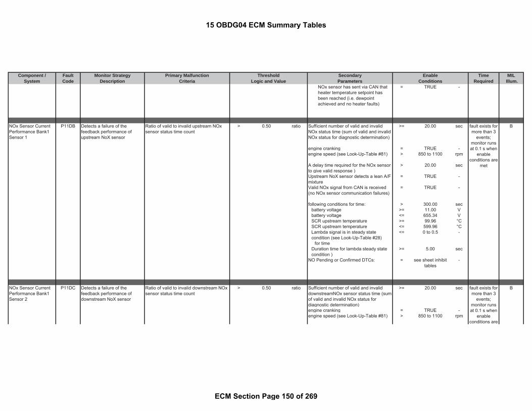
Component / Fault Monitor Strategy Primary Malfunction Secondary Time MILSystem Code Description Criteria Parameters Required Illum.
Threshold EnableLogic and Value Conditions
NOx sensor has sent via CAN thatheater temperature setpoint hasbeen reached (i.e. dewpointachieved and no heater faults)
= TRUE -
NOx Sensor CurrentPerformance Bank1Sensor 1
P11DB Detects a failure of thefeedback performance ofupstream NoX sensor
Ratio of valid to invalid upstream NOxsensor status time count
> 0.50 ratio Sufficient number of valid and invalidNOx status time (sum of valid and invalidNOx status for diagnostic determination)
>= 20.00 sec B
engine cranking = TRUE -engine speed (see Look-Up-Table #81) > 850 to 1100 rpm
A delay time required for the NOx sensorto give valid response )
> 20.00 sec
Upstream NoX sensor detects a lean A/Fmixture
= TRUE -
Valid NOx signal from CAN is received(no NOx sensor communication failures)
= TRUE -
following conditions for time: > 300.00 secbattery voltage >= 11.00 Vbattery voltage <= 655.34 VSCR upstream temperature >= 99.96 °CSCR upstream temperature <= 599.96 °CLambda signal is in steady statecondition (see Look-Up-Table #28)
<= 0 to 0.5 -
for timeDuration time for lambda steady statecondition )
>= 5.00 sec
NO Pending or Confirmed DTCs: = see sheet inhibittables
-
NOx Sensor CurrentPerformance Bank1Sensor 2
P11DC Detects a failure of thefeedback performance ofdownstream NoX sensor
Ratio of valid to invalid downstream NOxsensor status time count
> 0.50 ratio Sufficient number of valid and invaliddownstreamNOx sensor status time (sumof valid and invalid NOx status fordiagnostic determination)
>= 20.00 sec B
engine cranking = TRUE -engine speed (see Look-Up-Table #81) > 850 to 1100 rpm
fault exists formore than 3
events;monitor runsat 0.1 s when
enableconditions are
met
fault exists formore than 3
events;monitor runsat 0.1 s when
enableconditions are
15 OBDG04 ECM Summary Tables
ECM Section Page 150 of 269

Component / Fault Monitor Strategy Primary Malfunction Secondary Time MILSystem Code Description Criteria Parameters Required Illum.
Threshold EnableLogic and Value Conditions
A delay time required for the NOx sensorto give valid response )
> 20.00 sec
Downstream NoX sensor detects a leanA/F mixture
= TRUE -
Valid NOx signal from CAN is received(no NOx sensor communication failures)
= TRUE -
following conditions for time: > 300.00 secbattery voltage >= 11.00 Vbattery voltage <= 655.34 VSCR upstream temperature >= 99.96 °CSCR upstream temperature <= 599.96 °CDownstream Lambda signal is in steadystate condition (see Look-Up-Table#27)
<= 0 to 0.5 -
for timeDuration time for lambda steady statecondition )
>= 5.00 sec
NO Pending or Confirmed DTCs: = see sheet inhibittables
-
Intake Air Flow ValveControl CircuitShorted
P122C Electronic out-put drivercircuitry determines circuitintegrity on the intake air flowvalve.
The ECM detects that the commandedstate of the driver and the actual state ofthe control circuit do not match.
battery voltage > 11.00 V B
fortime > 3.00 sec
andstarter is active cranking = FALSE -
fortime > 3.00 sec
andbasic enable conditions met: = see sheet enable
tables-
andThrottle Valve Actuator Solenoid ControlCircuit
= ACTIVE -
andOpen Load Diagnosis active = FALSE -NO Pending or Confirmed DTCs = see sheet inhibit
tables-
met
fail conditionsexists for 0.5
smonitor runswith 0.005 s
rate wheneverenable
conditions aremet
15 OBDG04 ECM Summary Tables
ECM Section Page 151 of 269
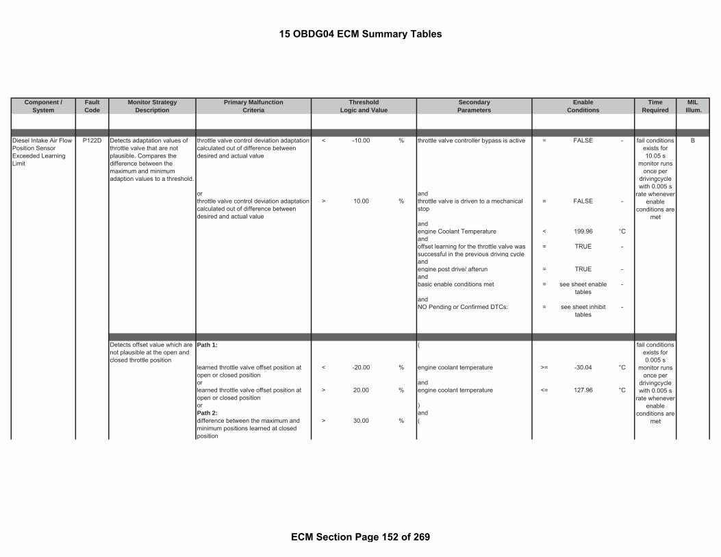
Component / Fault Monitor Strategy Primary Malfunction Secondary Time MILSystem Code Description Criteria Parameters Required Illum.
Threshold EnableLogic and Value Conditions
Diesel Intake Air FlowPosition SensorExceeded LearningLimit
P122D Detects adaptation values ofthrottle valve that are notplausible. Compares thedifference between themaximum and minimumadaption values to a threshold.
throttle valve control deviation adaptationcalculated out of difference betweendesired and actual value
< -10.00 % throttle valve controller bypass is active = FALSE - B
or andthrottle valve control deviation adaptationcalculated out of difference betweendesired and actual value
> 10.00 % throttle valve is driven to a mechanicalstop
= FALSE -
andengine Coolant Temperature < 199.96 °Candoffset learning for the throttle valve wassuccessful in the previous driving cycle
= TRUE -
andengine post drive/ afterun = TRUE -andbasic enable conditions met = see sheet enable
tables-
andNO Pending or Confirmed DTCs: = see sheet inhibit
tables-
Detects offset value which arenot plausible at the open andclosed throttle position
Path 1: (
learned throttle valve offset position atopen or closed position
< -20.00 % engine coolant temperature >= -30.04 °C
or andlearned throttle valve offset position atopen or closed position
> 20.00 % engine coolant temperature <= 127.96 °C
or )Path 2: anddifference between the maximum andminimum positions learned at closedposition
> 30.00 % (
fail conditionsexists for10.05 s
monitor runsonce per
drivingcyclewith 0.005 s
rate wheneverenable
conditions aremet
fail conditionsexists for0.005 s
monitor runsonce per
drivingcyclewith 0.005 s
rate wheneverenable
conditions aremet
15 OBDG04 ECM Summary Tables
ECM Section Page 152 of 269

Component / Fault Monitor Strategy Primary Malfunction Secondary Time MILSystem Code Description Criteria Parameters Required Illum.
Threshold EnableLogic and Value Conditions
or battery voltage >= 11.00 VPath 3:difference between the maximum andminimum positions learned at openposition
> 30.00 % and
battery voltage <= 655.34 V)andThrottle Valve is not frozen
consisting of:(temperature downstream charge aircooler
>= 6.06 °C
orEngine coolant temperature >= 6.06 °C
fortime > 10.00 sec
)andengine speed = 0 rpmandengine post drive/ afterun = TRUE -andNO Pending or Confirmed DTCs: see sheet inhibit
tables-
andbasic enable conditions met see sheet enable
tables-
Intake Air Flow ValveControl Circuit 2 LowVoltage
P122E Diagnoses the Throttle Valvehigh side driver circuit forcircuit faults.
Voltage low during driver on state(indicates short to ground)
= Short to ground: ≤ 0.5 Ωimpedancebetween signaland controllerground
- battery voltage > 11.00 V B
fortime > 3.00 sec
andstarter is active cranking = FALSE -
fortime > 3.00 sec
fail conditionsexists for 0,5
smonitor runswith 0.005 s
rate wheneverenable
conditions aremet
15 OBDG04 ECM Summary Tables
ECM Section Page 153 of 269

Component / Fault Monitor Strategy Primary Malfunction Secondary Time MILSystem Code Description Criteria Parameters Required Illum.
Threshold EnableLogic and Value Conditions
andbasic enable conditions met: = see sheet enable
tables-
andThrottle Valve Actuator Solenoid ControlCircuit
= ACTIVE -
andOpen Load Diagnosis active = FALSE -NO Pending or Confirmed DTCs = see sheet inhibit
tables-
Intake Air Flow ValveControl Circuit 2 HighVoltage
P122F Diagnoses the Throttle Valvehigh side driver circuit forcircuit faults.
Voltage high during driver off state(indicates short to power )
= Short to power: ≤0.5 Ω impedancebetween signaland controllerpower
- battery voltage > 11.00 V B
fortime > 3.00 sec
andstarter is active cranking = FALSE -
fortime > 3.00 sec
andbasic enable conditions met: = see sheet enable
tables-
andThrottle Valve Actuator Solenoid ControlCircuit
= ACTIVE -
andOpen Load Diagnosis active = FALSE -NO Pending or Confirmed DTCs = see sheet inhibit
tables-
fail conditionsexists for 0,5
smonitor runswith 0.005 s
rate wheneverenable
conditions aremet
15 OBDG04 ECM Summary Tables
ECM Section Page 154 of 269

Component / Fault Monitor Strategy Primary Malfunction Secondary Time MILSystem Code Description Criteria Parameters Required Illum.
Threshold EnableLogic and Value Conditions
Injector 1 ControlCircuit Shorted
P1248 Diagnoses the Injector Cylinder#1 high side driver circuit forcircuit faults.
Voltage low during driver on state(indicates short to ground)
= Short to ground: ≤ 0.5 Ωimpedancebetween signaland controllerground
- Engine Running (see parameterdefinition)
= TRUE - A
Injector 2 ControlCircuit Shorted
P1249 Diagnoses the Injector Cylinder#4 high side driver circuit forcircuit faults.
Voltage low during driver on state(indicates short to ground)
= Short to ground: ≤ 0.5 Ωimpedancebetween signaland controllerground
- Engine Running (see parameterdefinition)
= TRUE - A
Injector 3 ControlCircuit Shorted
P124A Diagnoses the Injector Cylinder#2 high side driver circuit forcircuit faults.
Voltage low during driver on state(indicates short to ground)
= Short to ground: ≤ 0.5 Ωimpedancebetween signaland controllerground
- Engine Running (see parameterdefinition)
= TRUE - A
fail conditionsexists formore than
0.04 smonitor runswith 0.01 s
rate wheneverenable
conditions aremet
fail conditionsexists formore than
0.04 smonitor runswith 0.01 s
rate wheneverenable
conditions aremet
fail conditionsexists formore than
0.04 smonitor runswith 0.01 s
rate wheneverenable
conditions aremet
15 OBDG04 ECM Summary Tables
ECM Section Page 155 of 269
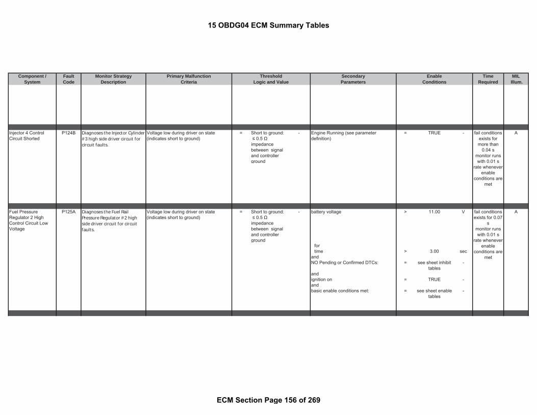
Component / Fault Monitor Strategy Primary Malfunction Secondary Time MILSystem Code Description Criteria Parameters Required Illum.
Threshold EnableLogic and Value Conditions
Injector 4 ControlCircuit Shorted
P124B Diagnoses the Injector Cylinder#3 high side driver circuit forcircuit faults.
Voltage low during driver on state(indicates short to ground)
= Short to ground: ≤ 0.5 Ωimpedancebetween signaland controllerground
- Engine Running (see parameterdefinition)
= TRUE - A
Fuel PressureRegulator 2 HighControl Circuit LowVoltage
P125A Diagnoses the Fuel RailPressure Regulator #2 highside driver circuit for circuitfaults.
Voltage low during driver on state(indicates short to ground)
= Short to ground: ≤ 0.5 Ωimpedancebetween signaland controllerground
- battery voltage > 11.00 V A
fortime > 3.00 sec
andNO Pending or Confirmed DTCs: = see sheet inhibit
tables-
andignition on = TRUE -andbasic enable conditions met: = see sheet enable
tables-
fail conditionsexists formore than
0.04 smonitor runswith 0.01 s
rate wheneverenable
conditions aremet
fail conditionsexists for 0.07
smonitor runswith 0.01 s
rate wheneverenable
conditions aremet
15 OBDG04 ECM Summary Tables
ECM Section Page 156 of 269

Component / Fault Monitor Strategy Primary Malfunction Secondary Time MILSystem Code Description Criteria Parameters Required Illum.
Threshold EnableLogic and Value Conditions
Fuel PressureRegulator 2 HighControl Circuit HighVoltage
P125B Diagnoses the Fuel RailPressure Regulator #2 highside driver circuit for circuitfaults.
Voltage high during driver off state(indicates short to power )
= Short to power: ≤0.5 Ω impedancebetween signaland controllerpower
- ( B
engine speed = 0 rpmorengine post drive/ afterun = TRUE -)and -NO Pending or Confirmed DTCs: = see sheet inhibit
tables-
fortime > 6.00 sec
andbasic enable conditions met: = see sheet enable
tables-
Fuel Rail PressurePerformance
P128E Actual rail pressure iscompared to fixed absolutevalue to detect low or high railpressure conditions.
rail pressure (see Look-Up-Table #62) < 0 to 15000 kPa ( A
state machine rail pressure controltransitioning pressure control valve mode
= TRUE -
orstate machine rail pressure controltransitioning to coupled pressure controlmode (rail pressure is controlled bymetering unit and pressure control valve)
= TRUE -
orstate machine rail pressure control equaltransitioning to metering unit pressurecontrol mode
= TRUE -
)andbasic enable conditions met: = see sheet enable
tables-
and
fail conditionsexists for 0.1
smonitor runswith 0.1s rate
wheneverenable
conditions aremet
fail conditionsexists for 2 smonitor runswith 0.02 s
rate wheneverenable
conditions aremet
15 OBDG04 ECM Summary Tables
ECM Section Page 157 of 269

Component / Fault Monitor Strategy Primary Malfunction Secondary Time MILSystem Code Description Criteria Parameters Required Illum.
Threshold EnableLogic and Value Conditions
NO Pending or Confirmed DTCs: = see sheet inhibittables
-
rail pressure (see Look-Up-Table #67) < 0 to 15000 kPa (state machine rail pressure control equalto pressure control valve
= TRUE -
orstate machine rail pressure control equalcoupled pressure control (rail pressure iscontrolled by metering unit and pressurecontrol valve)
= TRUE -
)andbasic enable conditions met: = see sheet enable
tables-
andNO Pending or Confirmed DTCs: = see sheet inhibit
tables
rail pressure (see Look-Up-Table #65) < 0 to 15000 kPa state machine rail pressure control equalto metering unit control mode
= TRUE -
andbasic enable conditions met: = see sheet enable
tables-
andNO Pending or Confirmed DTCs: = see sheet inhibit
tables-
rail pressure > 175000.00 kPa (state machine rail pressure controltransitioning pressure control valve mode
= TRUE -
or
fail conditionsexists for 1.01
s. monitorruns with 0.02
s rate
15 OBDG04 ECM Summary Tables
ECM Section Page 158 of 269

Component / Fault Monitor Strategy Primary Malfunction Secondary Time MILSystem Code Description Criteria Parameters Required Illum.
Threshold EnableLogic and Value Conditions
state machine rail pressure controltransitioning to coupled pressure controlmode (rail pressure is controlled bymetering unit and pressure control valve)
= TRUE -
orstate machine rail pressure control equaltransitioning to metering unit pressurecontrol mode
= TRUE -
)andbasic enable conditions met: = see sheet enable
tables-
andNO Pending or Confirmed DTCs: = see sheet inhibit
tables-
rail pressure > 175000.00 kPa (state machine rail pressure control equalto pressure control valve
= TRUE -
orstate machine rail pressure control equalcoupled pressure control (rail pressure iscontrolled by metering unit and pressurecontrol valve)
= TRUE -
)andbasic enable conditions met: = see sheet enable
tables-
andNO Pending or Confirmed DTCs: = see sheet inhibit
tables-
rail pressure > 175000.00 kPa state machine rail pressure control equalto metering unit control mode
= TRUE -
andbasic enable conditions met: = see sheet enable
tables-
and
wheneverenable
conditions aremet
15 OBDG04 ECM Summary Tables
ECM Section Page 159 of 269

Component / Fault Monitor Strategy Primary Malfunction Secondary Time MILSystem Code Description Criteria Parameters Required Illum.
Threshold EnableLogic and Value Conditions
NO Pending or Confirmed DTCs: = see sheet inhibittables
-
Intake ManifoldRunner ActuatorFeedback SignalCircuit Low
P12B0 Variable Swirl Valve positionfeedback signal (PWM) lowindicating and out of range lowfailure
variable swirl valve position sensor dutycycle
<= 5.00 % basic enable conditions met: = see sheet enabletables
- B
Intake ManifoldRunner ActuatorFeedback SignalCircuit High
P12B1 Variable Swirl Valve positionfeedback signal (PWM) lowindicating and out of range lowfailure
variable swirl valve position sensor dutycycle
>= 95.00 %
P1400 Path 1: BPilot Injection 1 is prohibited due toexceeding the allowed number ofinjections (see general description fordetails)
= TRUE - engine operating mode = exhaust / SCRheat-up
state bitmask
which means: or Cold Start Injection Monitoring = ENABLED -
andengine operating mode state transition = FALSE -
Path 2: and= TRUE - engine coolant temperature > -10.00 °C
andengine coolant temperature < 96.00 °C
or
Path 3:= TRUE -
fail conditionsexists for
more than 3 smonitor runs
0.1 s ratewhenever
enableconditions are
met
Cold Start EmissionReduction ControlSystem
Detects problems resulting inimproper delivery of fuel forcatalyst light off andaftertreatment systempreparation
fail conditionsexists for 20
revstest
performedcontinuously0.01 s rate
Pilot Injection 1 is prohibited due tocollision (overlap) with Main Injection andPilot Injection 2 (see general description
Injector circuit or activation errors(setpoint deviation) occurred when theinjector was being energized for Pilot
15 OBDG04 ECM Summary Tables
ECM Section Page 160 of 269
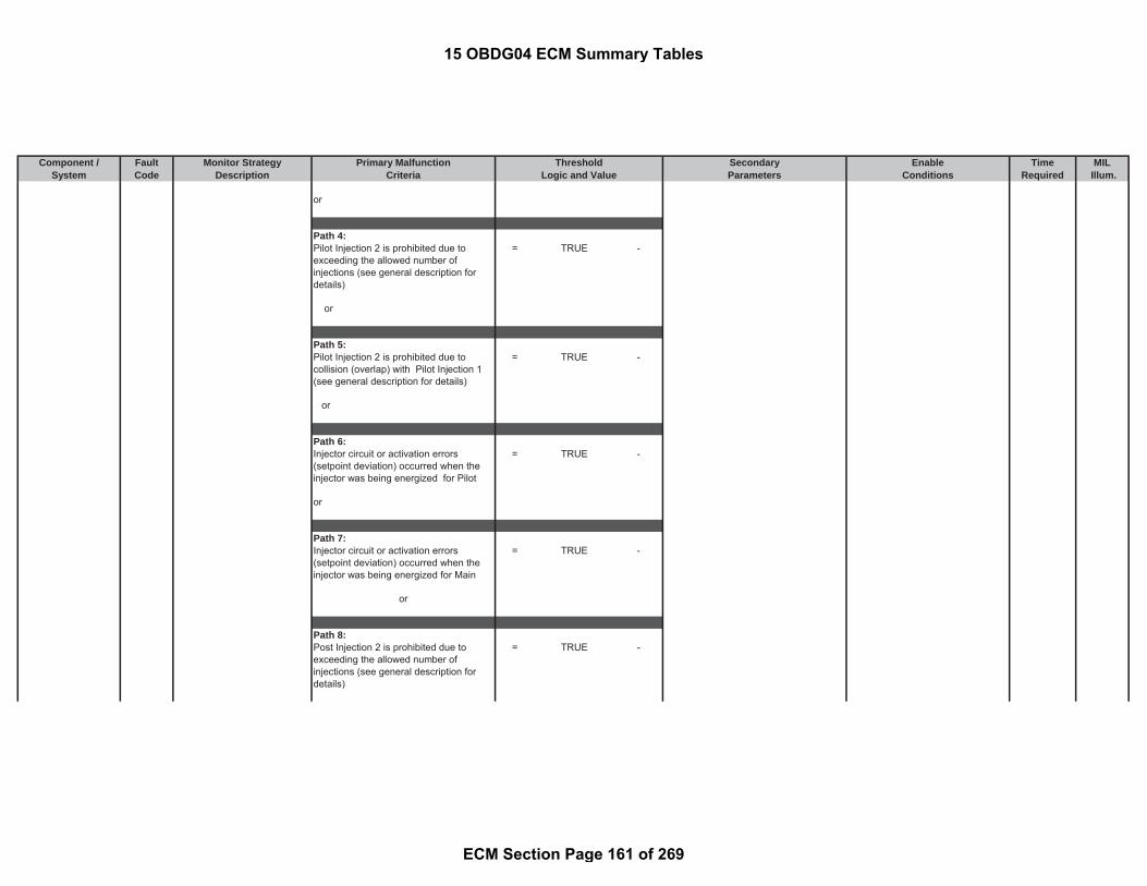
Component / Fault Monitor Strategy Primary Malfunction Secondary Time MILSystem Code Description Criteria Parameters Required Illum.
Threshold EnableLogic and Value Conditions
or
Path 4:Pilot Injection 2 is prohibited due toexceeding the allowed number ofinjections (see general description fordetails)
= TRUE -
or
Path 5:= TRUE -
or
Path 6:= TRUE -
or
Path 7:= TRUE -
or
Path 8:Post Injection 2 is prohibited due toexceeding the allowed number ofinjections (see general description fordetails)
= TRUE -
Pilot Injection 2 is prohibited due tocollision (overlap) with Pilot Injection 1(see general description for details)
Injector circuit or activation errors(setpoint deviation) occurred when theinjector was being energized for Pilot
Injector circuit or activation errors(setpoint deviation) occurred when theinjector was being energized for Main
15 OBDG04 ECM Summary Tables
ECM Section Page 161 of 269
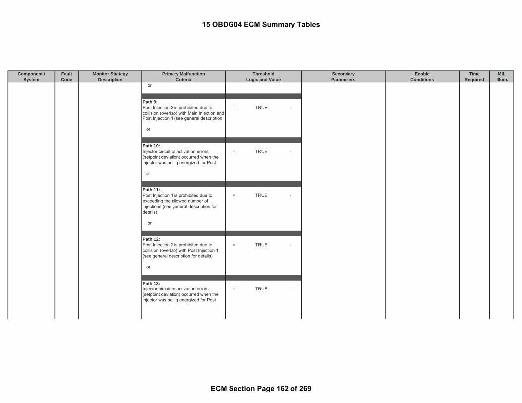
Component / Fault Monitor Strategy Primary Malfunction Secondary Time MILSystem Code Description Criteria Parameters Required Illum.
Threshold EnableLogic and Value Conditions
or
Path 9:= TRUE -
or
Path 10:= TRUE -
or
Path 11:Post Injection 1 is prohibited due toexceeding the allowed number ofinjections (see general description fordetails)
= TRUE -
or
Path 12:= TRUE -
or
Path 13:= TRUE -Injector circuit or activation errors
(setpoint deviation) occurred when theinjector was being energized for Post
Post Injection 2 is prohibited due tocollision (overlap) with Main Injection andPost Injection 1 (see general description
Injector circuit or activation errors(setpoint deviation) occurred when theinjector was being energized for Post
Post Injection 2 is prohibited due tocollision (overlap) with Post Injection 1(see general description for details)
15 OBDG04 ECM Summary Tables
ECM Section Page 162 of 269
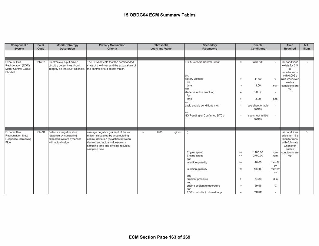
Component / Fault Monitor Strategy Primary Malfunction Secondary Time MILSystem Code Description Criteria Parameters Required Illum.
Threshold EnableLogic and Value Conditions
Exhaust GasRecirculation (EGR)Motor Control CircuitShorted
P1407 Electronic out-put drivercircuitry determines circuitintegrity on the EGR solenoid.
The ECM detects that the commandedstate of the driver and the actual state ofthe control circuit do not match.
EGR Solenoid Control Circuit = ACTIVE - B
andbattery voltage > 11.00 V
fortime > 3.00 sec
andstarter is active cranking = FALSE -
fortime > 3.00 sec
andbasic enable conditions met: = see sheet enable
tables-
andNO Pending or Confirmed DTCs = see sheet inhibit
tables-
Exhaust GasRecirculation SlowResponse-IncreasingFlow
P140B Detects a negative slowresponse by comparingexpected system dynamicswith actual value
average negative gradient of the airmass - calculated by accumulatingcontrol deviation (deviation betweendesired and actual value) over asampling time and dividing result bysampling time
> 0.05 g/rev ( B
Engine speed >= 1400.00 rpmEngine speed <= 2700.00 rpmandinjection quantity >= 40.00 mm^3/r
evinjection quantity <= 130.00 mm^3/r
evandambient pressure > 74.80 kPaandengine coolant temperature > 69.96 °CandEGR control is in closed loop = TRUE -
fail conditionsexists for 3,5
smonitor runswith 0.005 s
rate wheneverenable
conditions aremet
fail conditionsexists for 15 smonitor runswith 0.1s rate
wheneverenable
conditions aremet
15 OBDG04 ECM Summary Tables
ECM Section Page 163 of 269

Component / Fault Monitor Strategy Primary Malfunction Secondary Time MILSystem Code Description Criteria Parameters Required Illum.
Threshold EnableLogic and Value Conditions
for time > 1.50 secandEGR control is active = TRUE -
for time > 0.00 secandexhaust gas system regeneration mode = FALSE -
for time > 5.00 secandEngine is running = TRUE -
for time > 0.00 secandActuator position EGR Valve > 1.00 %Actuator position EGR Valve < 51.00 %andEngine speed >= 1500.00 rpmEngine speed <= 2600.00 rpmandinjection quantity >= 52.00 mm^3/r
evinjection quantity <= 100.00 mm^3/r
evanddesired delta air mass flow > -0.50 g/secdesired delta air mass flow < -0.03 g/secanddifference of the air mass < 0 g/revandNO Pending or Confirmed DTCs: = see sheet inhibit
tables-
)for time > 0.10 secandbasic enable conditions met: = see sheet enable
tables-
15 OBDG04 ECM Summary Tables
ECM Section Page 164 of 269

Component / Fault Monitor Strategy Primary Malfunction Secondary Time MILSystem Code Description Criteria Parameters Required Illum.
Threshold EnableLogic and Value Conditions
Exhaust GasRecirculation SlowResponse-DecreasingFlow
P140C Detects a positive slowresponse by comparingexpected system dynamicswith actual value
average positive gradient of the air mass -calculated by accumulating controldeviation (deviation between desired andactual value) over a sampling time anddividing result by sampling time
>= 0.04 g/rev ( B
Engine speed >= 1400.00 rpmEngine speed <= 2700.00 rpmandinjection quantity >= 40.00 mm^3/r
evinjection quantity <= 130.00 mm^3/r
evandambient pressure > 74.80 kPaandengine coolant temperature > 69.96 °CandEGR control is in closed loop = TRUE -for time > 1.50 secandEGR control is active = TRUE -for time > 0.00 secandexhaust gas system regeneration mode = FALSE -
for time > 5.00 secandEngine is running = TRUE -for time > 0.00 secandActuator position EGR Valve > 0.00 %Actuator position EGR Valve < 40.00 %andEngine speed >= 1500.00 rpmEngine speed <= 2600.00 rpmandinjection quantity >= 60.00 mm^3/r
evinjection quantity <= 120.00 mm^3/r
evanddesired delta air mass flow > 0.03 g/sec
fail conditionsexists for 15 smonitor runswith 0.1s rate
wheneverenable
conditions aremet
15 OBDG04 ECM Summary Tables
ECM Section Page 165 of 269

Component / Fault Monitor Strategy Primary Malfunction Secondary Time MILSystem Code Description Criteria Parameters Required Illum.
Threshold EnableLogic and Value Conditions
desired delta air mass flow < 0.70 g/secanddifference of the air mass > 0 g/revandNO Pending or Confirmed DTCs: = see sheet inhibit
tables-
)for time > 0.45 secandbasic enable conditions met: = see sheet enable
tables-
Exhaust GasRecirculation (EGR)Motor Control Circuit 2Low Voltage
P140D Diagnoses the EGR Valvehigh side driver circuit forcircuit faults.
Voltage low during driver on state(indicates short to ground)
= Short to ground: ≤ 0.5 Ωimpedancebetween signaland controllerground
- EGR Solenoid Control Circuit = ACTIVE - B
andbattery voltage > 11.00 V
fortime > 3.00 sec
andstarter is active cranking = FALSE -
fortime > 3.00 sec
andbasic enable conditions met: = see sheet enable
tables-
andNO Pending or Confirmed DTCs = see sheet inhibit
tables-
Exhaust GasRecirculation (EGR)Motor Control Circuit 2High Voltage
P140E Diagnoses the EGR Valvehigh side driver circuit forcircuit faults.
Voltage high during driver off state(indicates short to power )
= Short to power: ≤0.5 Ω impedancebetween signaland controllerpower
- EGR Solenoid Control Circuit = ACTIVE - B
fail conditionsexists for 3 smonitor runswith 0.005 s
rate wheneverenable
conditions aremet
fail conditionsexists for 3 smonitor runswith 0.005 s
rate wheneverenable
15 OBDG04 ECM Summary Tables
ECM Section Page 166 of 269
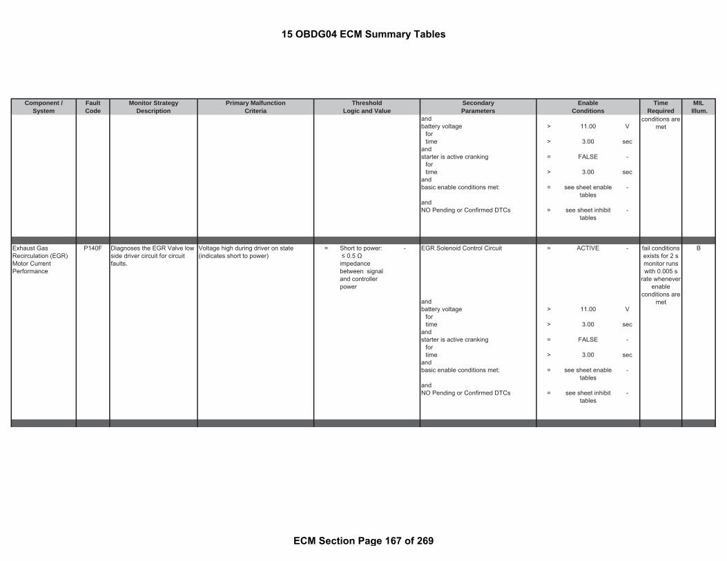
Component / Fault Monitor Strategy Primary Malfunction Secondary Time MILSystem Code Description Criteria Parameters Required Illum.
Threshold EnableLogic and Value Conditions
andbattery voltage > 11.00 V
fortime > 3.00 sec
andstarter is active cranking = FALSE -
fortime > 3.00 sec
andbasic enable conditions met: = see sheet enable
tables-
andNO Pending or Confirmed DTCs = see sheet inhibit
tables-
Exhaust GasRecirculation (EGR)Motor CurrentPerformance
P140F Diagnoses the EGR Valve lowside driver circuit for circuitfaults.
Voltage high during driver on state(indicates short to power)
= Short to power: ≤ 0.5 Ωimpedancebetween signaland controllerpower
- EGR Solenoid Control Circuit = ACTIVE - B
andbattery voltage > 11.00 V
fortime > 3.00 sec
andstarter is active cranking = FALSE -
fortime > 3.00 sec
andbasic enable conditions met: = see sheet enable
tables-
andNO Pending or Confirmed DTCs = see sheet inhibit
tables-
conditions aremet
fail conditionsexists for 2 smonitor runswith 0.005 s
rate wheneverenable
conditions aremet
15 OBDG04 ECM Summary Tables
ECM Section Page 167 of 269

Component / Fault Monitor Strategy Primary Malfunction Secondary Time MILSystem Code Description Criteria Parameters Required Illum.
Threshold EnableLogic and Value Conditions
Closed Loop DieselParticulate Filter(DPF) RegenerationControl At Limit -Stage 2 TemperatureToo Low
P144E Detects insufficient exhausttemperature or controldeviation during DPFregeneration. Temperaturereadings are compared todesired temperature values asan indication of an insufficientexhaust gas temperature.
commanded control value of the outercontrol loop of the temperature controller
>= 0.57 - controller deviation status is activedepending on engine operation point outof (see Look-Up-Table #24)
= 0 to 1 - A
and fordeviation from the temperature setpointfor outer control loop
> maximum of (a)or (b+(c-d))
°C time >= 12.50 sec
( andwith active operation mode of the outer
control loop= TRUE -
(a) limitation of the temperaturethreshold
= 70.00 °C means
and with ((b) temperature threshold value formaximum deviation
= 70 °C temperature upstream of the oxidationcatalyst
> 229.96 °C
and with and(c) desired temperature value of outercontrol loop of the exhaust gastemperature control
= calculatedparameter
- (
and with temperature downstream of theoxidation catalyst
> 219.96 °C
(d) temperature setpoint value ofouter control loop of the exhaust gastemperature control
= calculatedparameter
- and
) (temperature downstream of theoxidation catalyst
< 679.96 °C
andparticulate filter temperature foractivated post injection
< 679.96 °C
)andenvironmental pressure >= 74.80 kPaenvironmental temperature >= -20.04 °Cengine coolant temperature >= 49.96 °Cengine coolant temperature <= 125.96 °C
fail conditionsexists for 60 smonitor runs
with 0.1 s ratewhenever
enableconditions are
met
15 OBDG04 ECM Summary Tables
ECM Section Page 168 of 269

Component / Fault Monitor Strategy Primary Malfunction Secondary Time MILSystem Code Description Criteria Parameters Required Illum.
Threshold EnableLogic and Value Conditions
service DPF regeneration commanded(idle regen only commanded through GMtool)
= FALSE -
vehicle speed >= 9.37 mphvehicle speed <= 124.30 mphaccelerator pedal position > 3.00 %
for time > 3.00 secexhaust gas mass flow < 910.27 g/sec
for time >= 21474836.47 secandstable temperature conditions = TRUE -
means(temperature upstream of particulatefilter
> 500.00 °C
for time > 0.00 sec)
andbasic enable condition met: = see sheet enable
tables-
andNO Pending or Confirmed DTCs: = see sheet inhibit
tables-
Closed Loop DieselParticulate Filter(DPF) RegenerationControl At Limit -Stage 2 TemperatureToo High
P144F Detects insufficient exhausttemperature or controldeviation during DPFregeneration. Temperaturereadings are compared todesired temperature values asan indication of an excessiveexhaust gas temperature.
commanded control value of the outercontrol loop of the temperature controller
<= 0.10 - controller deviation status is activedepending on engine operation point outof (see Look-Up-Table #25)
= 0 to 1 - A
and fordeviation from the temperature setpointfor outer control loop
< minimum of (a)and (b-(c-d))
°C time >= 12.50 sec
( andwith active operation mode of the outer
control loop= TRUE -
fail conditionsexists for 60 smonitor runs
with 0.1 s ratewhenever
enableconditions are
met
15 OBDG04 ECM Summary Tables
ECM Section Page 169 of 269

Component / Fault Monitor Strategy Primary Malfunction Secondary Time MILSystem Code Description Criteria Parameters Required Illum.
Threshold EnableLogic and Value Conditions
(a) limitation of the temperaturethreshold
= -70.00 K means
and with ((b) temperature threshold value forminimum deviation
= -70 K temperature upstream of the oxidationcatalyst
> 229.96 °C
and with and(c) desired temperature value of outercontrol loop of the exhaust gastemperature control
= calculatedparameter
- (
and with temperature downstream of theoxidation catalyst
> 219.96 °C
(d) temperature setpoint value ofouter control loop of the exhaust gastemperature control
= calculatedparameter
- and
) (temperature downstream of theoxidation catalyst
< 679.96 °C
andparticulate filter temperature foractivated post injection
< 679.96 °C
)andenvironmental pressure >= 74.80 kPaenvironmental temperature >= -20.04 °Cengine coolant temperature >= 49.96 °Cengine coolant temperature <= 125.96 °Cservice DPF regeneration commanded(idle regen only commanded through GMtool)
= FALSE -
vehicle speed >= 9.37 mphvehicle speed <= 124.30 mphaccelerator pedal position > 3.00 %
for time > 3.00 secexhaust gas mass flow < 910.27 g/sec
for time >= 21474836.47 secandstable temperature conditions = TRUE -
means(temperature upstream of particulatefilter
> 500.00 °C
for time > 0.00 sec)
15 OBDG04 ECM Summary Tables
ECM Section Page 170 of 269

Component / Fault Monitor Strategy Primary Malfunction Secondary Time MILSystem Code Description Criteria Parameters Required Illum.
Threshold EnableLogic and Value Conditions
andbasic enable condition met: = see sheet enable
tables-
andNO Pending or Confirmed DTCs: = see sheet inhibit
tables-
Particulate MatterSensor SignalMessage CounterIncorrect
P1472 PM Sensor Control Unit(SCU) CAN communication:SCU signal data length isincorrect
SCU diagnostic signal data length isincorrect
= TRUE - Battery voltage (ECM) >= 11.00 V B
Ignition on = TRUE -for time > 1.20 sec
Particulate MatterSensor CompensationValue Missing/NotReceived
P147F Range check of sensorsensitivity calibration factor(detected failures: calibrationfactor manipulated, wrong ornot transmitted)
Path 1: Ignition on = TRUE - B
Sensitivity Factor adjustment value sentfrom the sensor control unit (SCU) in theengine ECM has been transmitted
= TRUE - SCU is in the state "ready" = TRUE -
Sensor sensitivity calibration factor < 0.75 factor meansOR Battery voltage (ECM) >= 11.00 VSensor sensitivity calibration factor > 1.25 factor
OR
Path 2:
fault exists formore than 1.4sec; monitorruns at 0.1 swhen enable
conditions aremet
fault exists formore than 0.1sec; monitorruns at 0.1 sonce per trip
15 OBDG04 ECM Summary Tables
ECM Section Page 171 of 269

Component / Fault Monitor Strategy Primary Malfunction Secondary Time MILSystem Code Description Criteria Parameters Required Illum.
Threshold EnableLogic and Value Conditions
Sensitivity Factor adjustment value sentfrom the sensor control unit (SCU) in theengine ECM has been transmitted
= FALSE -
Time after SCU "ready" until sensorsensitivity calibration factor transmitted
>= 2.00 sec
TCM Engine SpeedRequest SignalMessage CounterIncorrect
P150C Detects implausible enginespeed request informationreceived from the TCM
Path 1: ignition on = TRUE - A
( andnumber of messages with rolling count /protection value errors detected
>= 7.00 counts basic enable conditions met: = see sheet enabletables
-
with andnumber of consecutive frames = 10.00 counts NO Pending or Confirmed DTCs: = see sheet inhibit
tables-
)or
Path 2:(internal calculated checksum value fortransmission is not equal the receivedvalue
= TRUE -
andnumber of fault results > 5.00 counts)or
Path 3:time since last frame with valid protectionvalue was received from transmission
> 0.08 sec
Cruise Control SwitchData Integrity
P155A Set invalid data indicatedproblem on status of the cruiseswitch information
Switch state provided by Cruise Controlframe
= DATA INVALID - ignition on = TRUE - Special C
fail conditionsexists for 0.01
stest
performedcontinuously
0.01 s
fail conditionsexists for0.005 s
15 OBDG04 ECM Summary Tables
ECM Section Page 172 of 269

Component / Fault Monitor Strategy Primary Malfunction Secondary Time MILSystem Code Description Criteria Parameters Required Illum.
Threshold EnableLogic and Value Conditions
andinput circuit active = TRUE -
means:(Bus off or error passive on CAN = FALSE -andThe rolling counter and protectionvalue validation is enabled for thisCAN frame
= TRUE -
andFrame enabled. The EMC isauthorized to read the frame
= TRUE -
andProtection value error = FALSE -)
andbasic enable conditions met = see sheet enable
tables-
andNO Pending or Confirmed DTCs: = see sheet inhibit
tables-
Particulate FilterEfficiency BelowThreshold Bank 1
P2002 Monitoring of particulate filterefficiency using particulatesensor (PM sensor)
Path1: Particulate sensor is in the"measurement" state when failure occurs
= TRUE - B
measured and filtered interdigitalelectrode(IDE) current
> 12.00 uA which means
measured and filtered interdigitalelectrode(IDE) current
< 41.00 uA Sensor regeneration complete = TRUE -
when < andintegrated reciprocal of the predictedtrigger time
= 1.00 - PM sensor dewpoint achieved (pleasesee the definition)
= TRUE -
DPF regeneration not active TRUE -or Calculated soot particles mass based on
sensor flow resistance>= 0.00 g
Calculated soot particles mass based onsensor flow resistance
<= 300.00 g
Path2: (measured interdigital electrode(IDE)current
>= 41.00 uA Exhaust gas velocity at particulatesensor position
>= 0.00 m/sec
monitor runswith 0.005 s
rate wheneverenable
conditions aremet
fault exists formore than 1
event; monitorruns at 0.1 swhen enable
conditions aremet once per
trip
15 OBDG04 ECM Summary Tables
ECM Section Page 173 of 269

Component / Fault Monitor Strategy Primary Malfunction Secondary Time MILSystem Code Description Criteria Parameters Required Illum.
Threshold EnableLogic and Value Conditions
Exhaust gas velocity at particulatesensor position
<= 50.00 m/sec
then forIntegrated reciprocal of the predictedtrigger time
<= 1.00 - time >= 5.00 sec
when )waiting time for particulate sensorregeneration has elapsed
= 60.00 sec (
Exhaust gas pressure >= 75.00 kPaExhaust gas pressure <= 135.00 kPa
Note: Two sensor regenerationperformed following Path 2 test toconfirm sensor not electrically shorted(see general description for flowchartprocess for Path 2)
for
time >= 10.00 sec)(Exhaust gas temperature >= 64.96 °CExhaust gas temperature <= 399.96 °C
fortime >= 5.00 sec
)(Engine running = TRUE -(NOx sensor downstream concentration < 200.00 ppmtemperature of particulate matter sensor < 249.96 °C
)andNOx sensor downstream concentration < 1500.00 ppm
Intake ManifoldRunner ControlCircuit/Open Bank 1
P2008 Variable Swirl Valve actuatoropen circuit
Voltage low during driver off state(indicates open circuit)
= Open Circuit:200 K impedancebetween ECU pinand load
- basic enable conditions met: = see sheet enabletables
- Bfail conditionsexists for
more than 3 smonitor runs
0.1 s ratewhenever
enabledi i
15 OBDG04 ECM Summary Tables
ECM Section Page 174 of 269

Component / Fault Monitor Strategy Primary Malfunction Secondary Time MILSystem Code Description Criteria Parameters Required Illum.
Threshold EnableLogic and Value Conditions
Intake ManifoldRunner Control CircuitLow Bank 1
P2009 Variable Swirl valve actuatorshort circuit to ground
Voltage low during driver off state(indicates short-to-ground)
= Short to ground: 0.5
impedancebetween signaland controllerground
- basic enable conditions met: = see sheet enabletables
- B
Intake ManifoldRunner Control CircuitHigh Bank 1
P2010 Variable Swirl valve actuatorshort circuit to battery
Voltage high during driver on state(indicates short to power)
= Short to power: ≤ 0.5 Ωimpedancebetween signaland controllerpower
- basic enable conditions met: = see sheet enabletables
- B
conditions aremet
fail conditionsexists for
more than 3 smonitor runs
0.1 s ratewhenever
enableconditions are
met
fail conditionsexists for
more than 3 smonitor runs
0.1 s ratewhenever
enableconditions are
met
15 OBDG04 ECM Summary Tables
ECM Section Page 175 of 269

Component / Fault Monitor Strategy Primary Malfunction Secondary Time MILSystem Code Description Criteria Parameters Required Illum.
Threshold EnableLogic and Value Conditions
Intake ManifoldRunner PerformanceBank 1
P200A Monitors the commandedvariable swirl valve positionversus actual measured PWMposition for a negativedeviation
difference of the commanded variableswirl valve position from the actualmeasured variable swirl valve position
< -10.00 % basic enable conditions met: = see sheet enabletables
- B
NO Pending or Confirmed DTCs = see sheet inhibittables
-
Monitors the commandedvariable swirl valve positionversus actual measured PWMposition for a positive deviation
difference of the commanded variableswirl valve position from the actualmeasured variable swirl valve position
> 10 % basic enable conditions met: = see sheet enabletables
-
NO Pending or Confirmed DTCs = see sheet inhibittables
-
fail conditionsexists for
more than 5 smonitor runs
0.1 s ratewhenever
enableconditions are
met
fail conditionsexists for
more than 5 smonitor runs
0.1 s ratewhenever
enableconditions are
met
15 OBDG04 ECM Summary Tables
ECM Section Page 176 of 269

Component / Fault Monitor Strategy Primary Malfunction Secondary Time MILSystem Code Description Criteria Parameters Required Illum.
Threshold EnableLogic and Value Conditions
Monitors the commandedvariable swirl valve positionresponse time, in the afterrun,from an intrusivelycommanded closed to openposition
time required for variable swirl valve toreached open position
> 2.00 sec engine off time >= 5.00 sec
where battery voltage >= 11.00 Vvariable swirl valve open position < 33.20 % battery voltage <= 655.34 V
basic enable conditions met: = see sheet enabletables
-
NO Pending or Confirmed DTCs = see sheet inhibittables
-
Monitors the commandedvariable swirl valve positionresponse time, in the afterrun,from an intrusivelycommanded open to closedposition
time required for variable swirl valve toreached closed position
> 2.00 sec engine off time >= 5.00 sec
where battery voltage >= 11.00 Vvariable swirl valve open position > 80.80 % battery voltage <= 655.34 V
basic enable conditions met: = see sheet enabletables
-
NO Pending or Confirmed DTCs = see sheet inhibittables
-
fail conditionsexists for
more than 2 smonitor runs
0.1 s ratewhenever
enableconditions are
met
fail conditionsexists for
more than 2 smonitor runs
0.1 s ratewhenever
enableconditions are
met
15 OBDG04 ECM Summary Tables
ECM Section Page 177 of 269

Component / Fault Monitor Strategy Primary Malfunction Secondary Time MILSystem Code Description Criteria Parameters Required Illum.
Threshold EnableLogic and Value Conditions
Monitors the commandedvariable swirl valve positionresponse time, in the afterrun,from an intrusivelycommanded value (11%)which checks the linkageintegrity of the variable swirlvalve
variable swirl valve position < 75.00 % engine off time >= 5.00 sec
or battery voltage >= 11.00 Vvariable swirl valve position > 88.00 % battery voltage <= 655.34 V
basic enable conditions met: = see sheet enabletables
-
NO Pending or Confirmed DTCs = see sheet inhibittables
-
Exhaust GasTemperature (EGT)Sensor 2 Circuit LowVoltage
P2032 Detects low voltage readingson the EGT 2 circuit, indicatingan OOR low condition on theEGT 2 circuit
temperature sensor voltage downstreamof oxidation catalyst
< 0.55 V ignition on = TRUE - A
same as andtemperature downstream of oxidationcatalyst
< - 50 °C basic enable conditions met: = see sheet enabletables
-
fail conditionsexists for
more than 1 smonitor runs
0.1 s ratewhenever
enableconditions are
met
fail conditionsexists for 5 smonitor runs0.050 s ratewhenever
enableconditions are
met
15 OBDG04 ECM Summary Tables
ECM Section Page 178 of 269

Component / Fault Monitor Strategy Primary Malfunction Secondary Time MILSystem Code Description Criteria Parameters Required Illum.
Threshold EnableLogic and Value Conditions
Exhaust GasTemperature (EGT)Sensor 2 Circuit HighVoltage
P2033 Detects high voltage readingson the EGT 2 circuit, indicatingan OOR high condition on theEGT 2 circuit
temperature sensor voltage downstreamof oxidation catalyst
> 2.33 V ignition on = TRUE - A
same as andtemperature downstream of oxidationcatalyst
> 1000 °C basic enable conditions met: = see sheet enabletables
-
Reductant LevelSensor
P203B Reductant level plausibilitycheck error from CAN
CAN message "Reductant LevelPlausibility Check Error" from reductanttank level evaluation module
= TRUE - ignition on = TRUE - B
which means and( basic enable conditions met: = see sheet enable
tables-
( measured tank level sensor 2 voltageafter 1.5 ms since a test impulse wasapplied )
= ( 0.0 to 1.7 ) V and
( measured tank level sensor 1 voltageafter 1.5 ms since a test impulse wasapplied )
= ( 1.71 to 3.56 ) V NO Pending or Confirmed DTCs: = see sheet inhibittables
-
)or
(( measured tank level sensor 3 voltageafter 1.5 ms since a test impulse wasapplied )
= ( 0.0 to 1.7 ) V
( measured tank level sensor 1 voltageafter 1.5 ms since a test impulse wasapplied )
= ( 1.71 to 3.56 ) V
)or
(
fail conditionsexists for 5 smonitor runs0.050 s ratewhenever
enableconditions are
met
fail conditionsexists for 5 s
testperformed
continuously 1s rate
wheneverenable
conditions aremet
15 OBDG04 ECM Summary Tables
ECM Section Page 179 of 269

Component / Fault Monitor Strategy Primary Malfunction Secondary Time MILSystem Code Description Criteria Parameters Required Illum.
Threshold EnableLogic and Value Conditions
( measured tank level sensor 3 voltageafter 1.5 ms since a test impulse wasapplied )
= ( 0.0 to 1.7 ) V
( measured tank level sensor 2 voltageafter 1.5 ms since a test impulse wasapplied )
= ( 1.71 to 3.56 ) V
)
Reductant LevelSensor 1 Circuit Low
P203C CAN message: Discrete levelsensor level 1 short to grounderror
Reductant Tank Level 1 Error Status = 1 - ignition on = TRUE - B
( tank level sensor 1 voltage directlymeasured after a test impulse wasapplied )
< ( 0.17 ) V battery voltage > 8 V
basic enable conditions met: = see sheet enabletables
-
Reductant LevelSensor 1 Circuit High
P203D Path 1: A
CAN message: Discrete levelsensor 1 open load error
Reductant Tank Level 1 Error Status = 3 - ignition on = TRUE -
( measured tank level sensor 1 voltageafter 1.5 ms since a test impulse wasapplied )
> ( 3.56 ) V battery voltage > 8 V
( measured tank level sensor 1 voltageafter 1.5 ms since a test impulse wasapplied )
< ( 4.74 ) V basic enable conditions met: = see sheet enabletables
-
fail conditionsexists for
more than 3sec.
monitor runswith 0.01 s
rate wheneverenable
conditions aremet
fail conditionsexists for
more than 3sec
monitor runswith 1 s ratewhenever
enableconditions are
met
15 OBDG04 ECM Summary Tables
ECM Section Page 180 of 269

Component / Fault Monitor Strategy Primary Malfunction Secondary Time MILSystem Code Description Criteria Parameters Required Illum.
Threshold EnableLogic and Value Conditions
Path 2:CAN message: Discrete levelsensor 1 short to battery error
Reductant Tank Level 1 Error Status = 2 - ignition on = TRUE -
( measured tank level sensor 1 voltageafter 1.5 ms since a test impulse wasapplied )
> ( 4.74 ) V battery voltage > 8 V
basic enable conditions met: = see sheet enabletables
-
Reductant InjectorControl Circuit
P2047 Detects an open circuit or anovertemperature condition inthe Reductant Injector ControlCircuit
The ECM detects that the commandedstate of the driver and the actual state ofthe control circuit do not match. Voltagelow during driver off state (indicates opencircuit)
= Open Circuit:200 K impedancebetween ECU pinand load
- ignition on = TRUE - B
andECU Initialization tasks in progress = FALSE -
fortime > 0.10 sec
andBattery voltage > 10.50 V
fortime > 3.00 sec
andbasic enable conditions met: = see sheet enable
tables-
ANDNO Pending or Confirmed DTCs = see sheet inhibit
tables-
fail conditionsexists for
more than 3sec
monitor runswith 1 s ratewhenever
enableconditions are
met
fail conditionsexists for 5 smonitor runswith 0.010 s
rate wheneverenable
conditions aremet
15 OBDG04 ECM Summary Tables
ECM Section Page 181 of 269
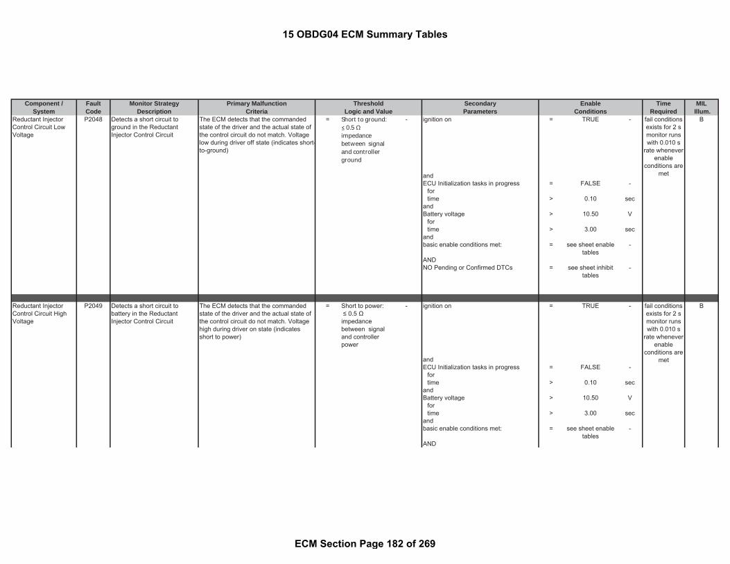
Component / Fault Monitor Strategy Primary Malfunction Secondary Time MILSystem Code Description Criteria Parameters Required Illum.
Threshold EnableLogic and Value Conditions
Reductant InjectorControl Circuit LowVoltage
P2048 Detects a short circuit toground in the ReductantInjector Control Circuit
The ECM detects that the commandedstate of the driver and the actual state ofthe control circuit do not match. Voltagelow during driver off state (indicates short-to-ground)
= Short to ground: 0.5
impedancebetween signaland controllerground
- ignition on = TRUE - B
andECU Initialization tasks in progress = FALSE -
fortime > 0.10 sec
andBattery voltage > 10.50 V
fortime > 3.00 sec
andbasic enable conditions met: = see sheet enable
tables-
ANDNO Pending or Confirmed DTCs = see sheet inhibit
tables-
Reductant InjectorControl Circuit HighVoltage
P2049 Detects a short circuit tobattery in the ReductantInjector Control Circuit
The ECM detects that the commandedstate of the driver and the actual state ofthe control circuit do not match. Voltagehigh during driver on state (indicatesshort to power)
= Short to power: ≤ 0.5 Ωimpedancebetween signaland controllerpower
- ignition on = TRUE - B
andECU Initialization tasks in progress = FALSE -
fortime > 0.10 sec
andBattery voltage > 10.50 V
fortime > 3.00 sec
andbasic enable conditions met: = see sheet enable
tables-
AND
fail conditionsexists for 2 smonitor runswith 0.010 s
rate wheneverenable
conditions aremet
fail conditionsexists for 2 smonitor runswith 0.010 s
rate wheneverenable
conditions aremet
15 OBDG04 ECM Summary Tables
ECM Section Page 182 of 269

Component / Fault Monitor Strategy Primary Malfunction Secondary Time MILSystem Code Description Criteria Parameters Required Illum.
Threshold EnableLogic and Value Conditions
NO Pending or Confirmed DTCs = see sheet inhibittables
-
Reductant PressureSensor CircuitRange/Performance
P204B Unfiltered reductant pressureis compared to a thresholdwhile the SCR system is in NoPressure Control state
Pressure sensor signal change duringNo Pressure Control state
> 50.00 kPa Reductant filling state in the pressure line <= 0.00 % B
andstatus of SCR control state (please seethe definition)
= No PressureControl
-
andState of the defrosting check of pressureline (please see the definition)
= TRUE -
andambient pressure > 0.00 kPaandambient temperature > -6.64 °CandNO Pending or Confirmed DTCs: = see sheet inhibit
tables -
andbasic enable conditions met: = see sheet enable
tables-
Reductant PressureSensor Circuit Low
P204C Measured reductant pumppressure sensor signal lowvoltage
Reductant pump pressure sensor signal < 0.41 V ignition on = TRUE - A
same as: NO Pending or Confirmed DTCs: = see sheetinhibit tables
-
reductant pump pressure < 0 kPa basic enable conditions met: = see sheet enabletables
-
fail conditionsexists for
more than 0.6sec
monitor runswith 0.01 s
rate wheneverenable
conditions aremet
fail conditionsexists formore than0.050 s.
monitor runswith 0.01 s
rate wheneverenable
conditions aremet
15 OBDG04 ECM Summary Tables
ECM Section Page 183 of 269

Component / Fault Monitor Strategy Primary Malfunction Secondary Time MILSystem Code Description Criteria Parameters Required Illum.
Threshold EnableLogic and Value Conditions
Reductant PressureSensor Circuit High
P204D Measured reductant pumppressure sensor signal highvoltage
Reductant pump pressure sensor signal > 4.80 V ignition on = TRUE - B
same as: NO Pending or Confirmed DTCs: = see sheetinhibit tables
-
reductant pump pressure > 800.00 kPa basic enable conditions met: = see sheet enabletables
-
Reductant SystemPerformance Bank 1
P204F Unsuccessful reductantpressure build up
Reductant Pump Module Pressure <= 375.00 kPa status of SCR control sub state (pleasesee the definition)
= PRESSUREBUILDUP
- A
ANDstatus byte in substatePRESSUREBUILDUP
= RUNNING
ANDReductant Defrost check(please see the definition)
= 1.00 -
ANDambient pressure > 0.00 kPaANDambient temperature > -30.04 °CANDnumber of pressure build-up attempts inpressure buildup and ventilation states
>= 20 counts
ANDDwell time in Pressure Build up substate >= 15.00 sec
ANDDwell time in ventilation substate >= 0.30 secANDUrea heater release reason ≠ COMPONENT
PROTECTION-
AND
fail conditionsexists for
more than 5sec.
monitor runswith 0.01 s
rate wheneverenable
conditions aremet
fail conditionsexists for 1
eventmonitor runs
with 0.1 s ratewhenever
enableconditions are
met
15 OBDG04 ECM Summary Tables
ECM Section Page 184 of 269

Component / Fault Monitor Strategy Primary Malfunction Secondary Time MILSystem Code Description Criteria Parameters Required Illum.
Threshold EnableLogic and Value Conditions
NO Pending or Confirmed DTCs: = see sheet inhibittables
-
ANDbasic enable conditions met: = see sheet enable
tables-
Reductant TankTemperature SensorPerformance
P205B Path 1: B
The temperature differencebetween reductant tanktemperature and diesel fueltemperature are compared toan upper threshold aftersufficient engine-off duration
(a) - (b) > 35.06 °C ignition on = TRUE -
where status of SCR control state (please seethe definition)
= No Pressurecontrol
-
(a) Reductant tank temperature = measuredparameter
- Engine off Time > 28800.00 sec
(b) fuel temperature = measuredparameter
- time since start > 600.00 sec
Max [(a), (b), (c)] - Min [(a), (b), (c)] <= 14.96 °Cwhere(a) Oxidation Catalyst upstreamtemperature
= measuredparameter
-
(b) Oxidation Catalyst downstreamtemperature
= measuredparameter
-
(c ) Particulate filter downstreamtemperature
= measuredparameter
-
NO Pending or Confirmed DTCs: = see sheet inhibittables
-
basic enable conditions met: = see sheet enabletables
-
\Path 2:OR ignition on = TRUE -
fail conditionsexists for
fail conditionsexists for
more than 0.5sec
monitor runswith 0.01 s
rate wheneverenable
conditions aremet
15 OBDG04 ECM Summary Tables
ECM Section Page 185 of 269

Component / Fault Monitor Strategy Primary Malfunction Secondary Time MILSystem Code Description Criteria Parameters Required Illum.
Threshold EnableLogic and Value Conditions
The temperature differencebetween reductant tanktemperature and diesel fueltemperature are compared toa lower threshold aftersufficient engine-off duration
(a) - (b) < -35.04 °C status of SCR control state (please seethe definition)
= No Pressurecontrol
-
where Engine off Time > 28800.00 sec(a) Reductant tank temperature = measured
parameter- time since start > 600.00 sec
(b) fuel temperature = measuredparameter
- Max [(a), (b), (c)] - Min [(a), (b), (c)] <= 14.96 °C
where(a) Oxidation Catalyst upstreamtemperature
= measuredparameter
-
(b) Oxidation Catalyst downstreamtemperature
= measuredparameter
-
(c ) Particulate filter downstreamtemperature
= measuredparameter
-
NO Pending or Confirmed DTCs: = see sheet inhibittables
-
basic enable conditions met: = see sheet enabletables
-
Reductant TankTemperature SensorCircuit Low
P205C Detects an out of range lowreading of the Reductant TankTemperature Sensor via CANMessage
Raw value of the CAN message for theReductant Tank Temperature
< 1.00 hex basic enable conditions met: = see sheet enabletables
- A
Corresponds to a temperature of <= -55.0 °C andCorresponds to a resistance of >= 1200 kOhm No rolling count or protection value
errors. (sliding window errors) in the CANframe
= TRUE -
Corresponds to a voltage of >= 5.0 V
more than0.5 sec
monitor runswith 0.01 s
rate wheneverenable
conditions aremet
fault exists formore than 6sec; monitorruns at 1 swhenever
enableconditions are
met
15 OBDG04 ECM Summary Tables
ECM Section Page 186 of 269

Component / Fault Monitor Strategy Primary Malfunction Secondary Time MILSystem Code Description Criteria Parameters Required Illum.
Threshold EnableLogic and Value Conditions
Reductant TankTemperature SensorCircuit High
P205D Detects an out of range highreading of the Reductant TankTemperature Sensor via CANMessage or an invalid(initialization) value of theReductant Tank TemperatureCAN message
Raw value of the CAN message for theReductant Tank Temperature
> 1022.00 dec basic enable conditions met: = see sheet enabletables
- B
Corresponds to a temperature of >= 160.0 °C andCorresponds to a resistance of <= 0.153 kOhm No rolling count or protection value
errors. (sliding window errors) in the CANframe
= TRUE -
Corresponds to a voltage of <= 0.270 V
Raw value of the CAN message for theReductant Tank Temperature
= 0x3FF1023
hexdec
Exhaust TemperatureSensor 1 Performance
P2080 Detects a fault in the exhausttemperature sensor 1performance by comparing theheat quantity on the sensorposition to a threshold.
integrated heat quantity of exhaust gastemperature sensor 1
< (a) / (b) * (c) / (d)* (e) * (f)
- exhaust gas system regeneration mode = FALSE B
or forintegrated heat quantity of exhaust gastemperature sensor 1
> (a) / (b) * (c) / (d)* (e) * (g)
- time > 120.00 sec
with and(a) exhaust gas mass flow = calculated
parameter- time since start > 120.00 sec
and with and(b) factor 3.60 g/sec (and with exhaust-gas temperature sensor 1 > -20.04 °C(c) heat capacity = 1200.00 J/Kg/°C andand with exhaust-gas temperature sensor 1 < 499.96 °C(d) factor = 1000 kW/°C )and with and(e) correction factor for heat flowquantity depending on exhaust gasmass flow for temperature sensor 1
= 1.00 factor change in exhaust-gas temperaturesensor 1
< 20.00 °C
for
fault exists formore than 6sec; monitorruns at 1 swhenever
enableconditions are
met
fail conditionsexists for 3smonitor runs
with 0.1 s ratewhenever
enableconditions are
met
15 OBDG04 ECM Summary Tables
ECM Section Page 187 of 269

Component / Fault Monitor Strategy Primary Malfunction Secondary Time MILSystem Code Description Criteria Parameters Required Illum.
Threshold EnableLogic and Value Conditions
and with time = 10.00 sec(f) minimum permissible temperaturedeviation for exhaust gas temperaturesensor 1
= -120.00 °C and
and with engine operation point suitable fordiagnostic
=255 255 -
(g) maximum permissible temperaturedeviation for exhaust gas temperaturesensor 1
= 100.00 °C for
time >= 0.05 secandchange in modeled exhaust-gastemperature sensor 1
> 20.00 °C
and(heat quantity for exhaust gastemperature sensor 1
> 20.00 kJ
andheat quantity for exhaust gastemperature sensor 1
< 40.00 kJ
)andengine has been in normal mode for time >= 120.00 sec
orengine has been in exhaust warm-upmode for time
>= 120.00 sec
andbasic enable conditions met: = see sheet enable
tables-
andNO Pending or Confirmed DTCs: = see sheet inhibit
tables-
Exhaust TemperatureSensor 2 Performance
P2084 Detects a fault in the exhausttemperature sensor 2performance by comparing theheat quantity on the sensorposition to a threshold.
integrated heat quantity of exhaust gastemperature sensor 2
< (a) / (b) * (c) / (d)* (e) * (f)
exhaust gas system regeneration mode = FALSE B
or for
fail conditionsexists for 3smonitor runs
with 0.1 s ratewhenever
enableconditions are
15 OBDG04 ECM Summary Tables
ECM Section Page 188 of 269

Component / Fault Monitor Strategy Primary Malfunction Secondary Time MILSystem Code Description Criteria Parameters Required Illum.
Threshold EnableLogic and Value Conditions
integrated heat quantity of exhaust gastemperature sensor 2
> (a) / (b) * (c) / (d)* (e) * (g)
time > 240.00 sec
with and(a) exhaust gas mass flow = calculated
parameter- time since start > 120.00 sec
and with and(b) factor = 3.60 g/sec (and with exhaust-gas temperature sensor 2 > -20.04 °C(c) heat capacity = 1200.00 J/Kg/°C andand with exhaust-gas temperature sensor 2 < 499.96 °C(d) factor = 1000 kW/°C )and with and(e) correction factor for heat flowquantity depending on exhaust gasmass flow for temperature sensor 2
= 1.00 factor change in exhaust-gas temperaturesensor 2
< 30.00 °C
forand with time = 10.00 sec(f) minimum permissible temperaturedeviation for exhaust gas temperaturesensor 2
= -140.00 K and
and with engine operation point suitable fordiagnostic
= 255 -
(g) maximum permissible temperaturedeviation for exhaust gas temperaturesensor 2
= 100.00 K for
time >= 0.05 secandchange in modeled exhaust-gastemperature sensor 2
> 20.00 °C
and(heat quantity for exhaust gastemperature sensor 2
> 20.00 kJ
andheat quantity for exhaust gastemperature sensor 2
< 40.00 kJ
)andengine has been in normal mode for time >= 120.00 sec
orengine has been in exhaust warm-upmode for time
>= 120.00 sec
met
15 OBDG04 ECM Summary Tables
ECM Section Page 189 of 269

Component / Fault Monitor Strategy Primary Malfunction Secondary Time MILSystem Code Description Criteria Parameters Required Illum.
Threshold EnableLogic and Value Conditions
andbasic enable conditions met: = see sheet enable
tables-
andNO Pending or Confirmed DTCs: = see sheet inhibit
tables-
Exhaust TemperatureSensor 3 Performance
P242B Detects a fault in the exhausttemperature sensor 3performance by comparing theheat quantity on the sensorposition to a threshold.
integrated heat quantity of exhaust gastemperature sensor 3
< (a) / (b) * (c) / (d)* (e) * (f)
exhaust gas system regeneration mode = FALSE B
or forintegrated heat quantity of exhaust gastemperature sensor 3
> (a) / (b) * (c) / (d)* (e) * (g)
time > 240.00 sec
with and(a) exhaust gas mass flow = calculated
parameter- time since start > 120.00 sec
and with and(b) factor = 3.60 g/sec (and with exhaust-gas temperature sensor 3 > -20.04 °C(c) heat capacity = 1200.00 J/Kg/°C andand with exhaust-gas temperature sensor 3 < 499.96 °C(d) factor = 1000 kW/°C )and with and(e) correction factor for heat flowquantity depending on exhaust gasmass flow for temperature sensor 3
= 1.00 factor change in exhaust-gas temperaturesensor 3
< 30.00 °C
forand with time = 10.00 sec(f) minimum permissible temperaturedeviation for exhaust gas temperaturesensor 3
= -120.00 K and
and with engine operation point suitable fordiagnostic
= 255 -
(g) maximum permissible temperaturedeviation for exhaust gas temperaturesensor 3
= 100.00 K for
time >= 0.05 secand
fail conditionsexists for 3smonitor runs
with 0.1 s ratewhenever
enableconditions are
met
15 OBDG04 ECM Summary Tables
ECM Section Page 190 of 269

Component / Fault Monitor Strategy Primary Malfunction Secondary Time MILSystem Code Description Criteria Parameters Required Illum.
Threshold EnableLogic and Value Conditions
change in modeled exhaust-gastemperature sensor 3
> 15.00 °C
and(heat quantity for exhaust gastemperature sensor 3
> 20.00 kJ
andheat quantity for exhaust gastemperature sensor 3
< 40.00 kJ
)andengine has been in normal mode for time >= 120.00 sec
orengine has been in exhaust warm-upmode for time
>= 120.00 sec
andbasic enable conditions met: = see sheet enable
tables-
andNO Pending or Confirmed DTCs: = see sheet inhibit
tables-
Reductant PumpControl Circuit
P208A Diagnoses the ReductantPump Motor low side drivercircuit for circuit faults.
Voltage low during driver off state(indicates short-to-ground)
The ECM detects that the commandedstate of the driver and the actual state ofthe control circuit do not match.
= Short to ground: 0.5
impedancebetween signaland controllerground
- ignition on = TRUE - A
andECU Initialization tasks in progress = FALSE -
fortime > 0.10 sec
andBattery voltage > 10.50 V
fortime > 3.00 sec
andbasic enable conditions met: = see sheet enable
tables-
fail conditionsexists for 6.2
smonitor runswith 0.10 s
rate wheneverenable
conditions aremet
15 OBDG04 ECM Summary Tables
ECM Section Page 191 of 269

Component / Fault Monitor Strategy Primary Malfunction Secondary Time MILSystem Code Description Criteria Parameters Required Illum.
Threshold EnableLogic and Value Conditions
ANDNO Pending or Confirmed DTCs = see sheet inhibit
tables-
Reductant PumpPerformance
P208B The ECM detects that thecommanded state of theReductant Pump driver andthe actual state of the controlcircuit do not match.
timer for functional acknowledgement ofthe reductant pump motor
> 4 sec ( B
timer for functional acknowledgement ofthe reductant pump motor
<= 6 sec Reductant Pump Warm-up status = FALSE -
where the Warm-up state is defined as:
(No Pressure control state (please seethe definition)
= TRUE -
SCR Engine State (please see thedefinition)
= ON -
((Remaining defrosting time of thetank
> 0 sec
Remaining defrosting time of thetank
<= 120 sec
)ORReductant Defrost check (pleasesee the definition)
= TRUE -
)))(ambient temperature > -100.00 deg C)basic enable conditions met: = see sheet enable
tables-
fault exists formore than 0.3
s;monitor runs
at 0.1 swhenever
enableconditions are
met
15 OBDG04 ECM Summary Tables
ECM Section Page 192 of 269
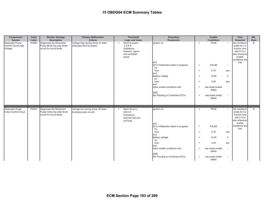
Component / Fault Monitor Strategy Primary Malfunction Secondary Time MILSystem Code Description Criteria Parameters Required Illum.
Threshold EnableLogic and Value Conditions
Reductant PumpControl Circuit HighVoltage
P208D Diagnoses the ReductantPump Motor low side drivercircuit for circuit faults.
Voltage high during driver on state(indicates short to power)
= Short to power: ≤ 0.5 Ωimpedancebetween signaland controllerpower
- ignition on = TRUE - B
andECU Initialization tasks in progress = FALSE -
fortime > 0.10 sec
andBattery voltage > 10.50 V
fortime > 3.00 sec
andbasic enable conditions met: = see sheet enable
tables-
ANDNO Pending or Confirmed DTCs = see sheet inhibit
tables-
Reductant PurgeValve Control Circuit
P20A0 Diagnoses the ReductantPurge Valve low side drivercircuit for circuit faults.
Voltage low during driver off state(indicates open circuit)
= Open Circuit:200 K impedancebetween ECU pinand load
- ignition on = TRUE - A
andECU Initialization tasks in progress = FALSE -
fortime > 0.10 sec
andBattery voltage > 10.50 V
fortime > 3.00 sec
andbasic enable conditions met: = see sheet enable
tables-
ANDNO Pending or Confirmed DTCs = see sheet inhibit
tables-
fail conditionsexists for 3 smonitor runswith 0.10 s
rate wheneverenable
conditions aremet
fail conditionsexists for 3 smonitor runswith 0.10 s
rate wheneverenable
conditions aremet
15 OBDG04 ECM Summary Tables
ECM Section Page 193 of 269

Component / Fault Monitor Strategy Primary Malfunction Secondary Time MILSystem Code Description Criteria Parameters Required Illum.
Threshold EnableLogic and Value Conditions
Reverting ValvePerformance
P20A1 This diagnostic checks thereverting valve performanceduring operation by detecting alack of reduction of thereductant pressure
Difference between reductant pumppressure at beginning and end ofpressure reduction phase
< 0.00 kPa ( A
Reductant Dosing System state pressurereduction
= TRUE -
Reductant Dosing System pump relativepressure to initiate test
>= 350.00 kPa
)AND((Time attempting to reduce dosingpressure
>= 20.00 sec
ANDReductant Dosing System pump relativepressure after attempting to reducepressure
> 100.00 kPa
)ORReductant Dosing System pumprelative pressure after attempting toreduce pressure
<= 100.00 kPa
)(ambient pressure > 0.00 kPaambient temperature > -40.04 °C)NO Pending or Confirmed DTCs = see sheet inhibit
tables-
basic enable conditions met: = see sheet enabletables
-
fault exists formore than 1
event monitorruns with 0.1
s ratewhenever
enableconditions are
met
15 OBDG04 ECM Summary Tables
ECM Section Page 194 of 269

Component / Fault Monitor Strategy Primary Malfunction Secondary Time MILSystem Code Description Criteria Parameters Required Illum.
Threshold EnableLogic and Value Conditions
Reductant PurgeValve Control CircuitLow Voltage
P20A2 Diagnoses the ReductantPurge Valve low side drivercircuit for circuit faults.
Voltage low during driver off state(indicates short-to-ground)
= Short to ground: 0.5
impedancebetween signaland controllerground
- ignition on = TRUE - B
andECU Initialization tasks in progress = FALSE -
fortime > 0.10 sec
andBattery voltage > 10.50 V
fortime > 3.00 sec
andbasic enable conditions met: = see sheet enable
tables-
ANDNO Pending or Confirmed DTCs = see sheet inhibit
tables-
Reductant PurgeValve Control CircuitHigh Voltage
P20A3 Diagnoses the ReductantPurge Valve low side drivercircuit for circuit faults.
Voltage high during driver on state(indicates short to power)
= Short to power: ≤ 0.5 Ωimpedancebetween signaland controllerpower
- ignition on = TRUE - B
andECU Initialization tasks in progress = FALSE -
fortime > 0.10 sec
andBattery voltage > 10.50 V
fortime > 3.00 sec
andbasic enable conditions met: = see sheet enable
tables-
AND
fail conditionsexists for 2 smonitor runswith 0.01 secrate whenever
enableconditions are
met
fail conditionsexists for 3 smonitor runswith 0.01 secrate whenever
enableconditions are
met
15 OBDG04 ECM Summary Tables
ECM Section Page 195 of 269

Component / Fault Monitor Strategy Primary Malfunction Secondary Time MILSystem Code Description Criteria Parameters Required Illum.
Threshold EnableLogic and Value Conditions
NO Pending or Confirmed DTCs = see sheet inhibittables
-
Exhaust GasTemperature (EGT)Sensors 1-2 notplausible
P20E2 Detects biased exhausttemperature sensors bycomparing the upstream anddownstream oxidation catalysttemperature sensors after acalibrated engine off soak time
Path 1: minimum engine-off time >= 28800.00 sec B
|(a) - (b)| (see Look-Up-Table #31) > 20 to 3276.7 °C andwith ambient temperature > -50.04 °C
(a) captured oxidation catalystdownstream temperature at start
= measuredparameter
- and
and with Engine Running (see parameterdefinition)
= TRUE -
(b) captured oxidation catalystupstream temperature at start asreference temperature
= measuredparameter
- for
time > 0.10 secandengine post drive/ afterun = FALSE -anddiagnostic performed in current dc = FALSE -andbasic enable conditions met: = see sheet enable
tables-
andNO Pending or Confirmed DTCs: = see sheet inhibit
tables-
Exhaust GasTemperature Sensor2/3 Correlation Bank 1
P20E4 Detects biased exhausttemperature sensors bycomparing the upstream anddownstream particulate filtertemperature sensors after acalibrated engine off soak time
Path 1: minimum engine-off time >= 28800.00 sec B
fail conditionsexists for0.050 s
monitor runswith 0.050 s
rate wheneverenable
conditions aremet
fail conditionsexists for0.050 s
monitor runswith 0.050 s
rate wheneverenable
15 OBDG04 ECM Summary Tables
ECM Section Page 196 of 269

Component / Fault Monitor Strategy Primary Malfunction Secondary Time MILSystem Code Description Criteria Parameters Required Illum.
Threshold EnableLogic and Value Conditions
|(a) - (b)| (see Look-Up-Table #32) > 20 to 3276.7 °C andwith ambient temperature > -50.04 °C
(a) captured particle filter downstreamtemperature at start
= measuredparameter
- and
and with Engine Running (see parameterdefinition)
= TRUE -
(b) captured particle filter upstreamtemperature at start as referencetemperature
= measuredparameter
- for
time > 0.10 secandengine post drive/ afterun = FALSE -anddiagnostic performed in current dc = FALSE -andbasic enable conditions met: = see sheet enable
tables-
andNO Pending or Confirmed DTCs: = see sheet inhibit
tables-
Reductant PressureToo Low
P20E8 Compare Reductant tankpressure with lower thresholdsunder metering control
Reductant Pump Module Pressure < 420.00 kPa B
status of SCR control sub state (pleasesee the definition)
= Metering control -
ANDstatus byte in substate METERINGCONTROL
= Running
ANDDwell time in Metering control substate > 2.00 secANDambient pressure > 0.00 kPaANDambient temperature > -30.04 °CANDNO Pending or Confirmed DTCs: = see sheet inhibit
tables-
AND
conditions aremet
fail conditionsexists formore than
60.0 smonitor runs
with 0.1 s ratewhenever
enableconditions are
met
15 OBDG04 ECM Summary Tables
ECM Section Page 197 of 269

Component / Fault Monitor Strategy Primary Malfunction Secondary Time MILSystem Code Description Criteria Parameters Required Illum.
Threshold EnableLogic and Value Conditions
basic enable conditions met: = see sheet enabletables
-
Reductant PressureToo High
P20E9 Path 1: B
Compare Reductant tankpressure with upper thresholdunder metering control
Reductant Pump Module Pressure > 650.00 kPa status of SCR control sub state (pleasesee the definition)
= Metering control -
ANDstatus byte in substate METERINGCONTROL
= Running -
ANDDwell time in Metering control substate > 2.00 secANDambient pressure > 0.00 kPaANDambient temperature > -30.04 °CANDNO Pending or Confirmed DTCs: = see sheet inhibit
tables-
ANDbasic enable conditions met: = see sheet enable
tables-
Path 2:OrReductant tank pressure high Unfiltered Reductant Pump Module
Pressure>= 795.00 kPa ambient pressure > 0.00 kPa
ANDambient temperature > -30.04 °CANDbasic enable conditions met: = see sheet enable
tables-
fail conditionsexists for
more than 10s
monitor runswith 0.1 s rate
wheneverenable
conditions aremet
fail conditionsexists for
more than 1 smonitor runs
with 0.1 s ratewhenever
enableconditions are
met
15 OBDG04 ECM Summary Tables
ECM Section Page 198 of 269

Component / Fault Monitor Strategy Primary Malfunction Secondary Time MILSystem Code Description Criteria Parameters Required Illum.
Threshold EnableLogic and Value Conditions
SCR NOx CatalystEfficiency BelowThreshold Bank 1
P20EE Compare EWMA filtered NOxconversion efficiency of SCRcatalyst with a threshold value
EWMA filtered delta SCR catalystefficiency of (a) - (b)
< 0.00 factor NO Pending or Confirmed DTCs: = see sheetinhibit tables
- A
where for time > 10.00 sec(a) measured SCR catalyst efficiency = measured
parameterfactor and
(b) offset-corrected modeled SCRcatalyst efficiency (please see thegeneral description for details) (seeLook-Up-Table #68)
= -0.273 to -0.17 factor Status of NOx signal of upstream NOxsensor (please see the definition)
= Active -
for time > 120.00 secStatus of NOx signal of downstream NOxsensor (please see the definition)
= Active -
for time > 120.00 sec
(Release of dosing strategy (please seethe definition)
= TRUE -
for time >= (a) + (b) sec(a) Turn on delay time 1 of statusmetering strategy
= 180.00 sec
(b) Turn on delay time 2 of statusmetering strategy
= 20.00 sec
)and(Status for disabling SCR Efficiencymonitoring following an SCR Adaptationcompletion (please see the definition)
= FALSE -
for time > (a) + (b) sec(a) Debounce time after pre controlleddosing over
= 0.50 sec
(b) delay time the status of disablingSCR Efficiency monitoring
= 220.00 sec
orintegrated upstream NOx >= 1.50 g)
(
fail conditionsexists for
more than 1event
monitor runswith 0.01 s
rate wheneverenable
conditions aremet
15 OBDG04 ECM Summary Tables
ECM Section Page 199 of 269

Component / Fault Monitor Strategy Primary Malfunction Secondary Time MILSystem Code Description Criteria Parameters Required Illum.
Threshold EnableLogic and Value Conditions
Status of pre controlled dosing (pleasesee the definition)
= FALSE -
for time > (a) + (b)(a) Debounce time after pre controlleddosing off
= 0.50 sec
(b) Delay time after pre controlleddosing off
= 220.00 sec
orintegrated upstream NOx >= 1.50 g)and(Decrease of Reductant load level (pleasesee the definition)
= FALSE -
for time > 300.00 sec)and(Average slow filtered NOx mass flowupstream SCR
<= 0.09 g/sec
for time > 0.50 secMonitor disable time based on averageNOx mass flow and the time (see Look-Up-Table #79)
> 0 to 60 sec
)andfor time with > 12.00 sec
((SCR temperature gradient (see Look-Up-Table #77)
< 1.36 to 3.96 °C
SCR temperature gradient (see Look-Up-Table #78)
> -4.04 to -2.04 °C
filtered SCR catalyst temperature <= 350.06 °Cfiltered SCR catalyst temperature >= 215.06 °C)normalized HC load in SCR catalyst > 4.00 factorambient pressure >= 75.00 kPaambient temperature >= -11.04 °CDPF Regeneration in progress = FALSE -integrated upstream NOx during SCRadaptation plausibility check active
>= 2.00 g
15 OBDG04 ECM Summary Tables
ECM Section Page 200 of 269

Component / Fault Monitor Strategy Primary Malfunction Secondary Time MILSystem Code Description Criteria Parameters Required Illum.
Threshold EnableLogic and Value Conditions
Status of the SCR adaptationplausibility check active (please see thedefinition)
= FALSE -
for time > 120.00 sec)
SCR NOx Catalyst Efficiency BelowThreshold Bank 1 was performed for thecurrent driving cycle
= FALSE -
(engine speed >= -16384.00 rpmengine speed <= 16383.50 rpm
for time > 0.00 sec)SCR estimated current Reductant load(see Look-Up-Table #72)
>= 0.196 to 1.394 g
SCR estimated current Reductant load(see Look-Up-Table #71)
<= 0.23 to 1.64 g
(Status of the SCR adaptation plausibilitycheck active (please see the definition)
= FALSE -
withfor time > 120.00 sec
)Integrated NOx mass upstream SCR(see Look-Up-Table #73)
> 0.65 to 5.5 g
for time > 0.00 sec
Average SCR Temperature <= 350.06 °CAverage SCR Temperature >= 220.06 °CFiltered and delayed upstream NOx rawemission
<= 800.00 ppm
Filtered and delayed upstream NOx rawemission
>= 40.00 ppm
Filtered and delayed NOx raw emissionmass flow upstream of SCR
<= 0.08 g/sec
Filtered and delayed NOx raw emissionmass flow upstream of SCR
>= 0.00 g/sec
Filtered exhaust gas mass flow <= 63.88 g/secFiltered exhaust gas mass flow >= 10.00 g/secMAP for valid engine operation points forSCR efficiency monitoring
= 1 factor
for time > 1.20 sec
15 OBDG04 ECM Summary Tables
ECM Section Page 201 of 269

Component / Fault Monitor Strategy Primary Malfunction Secondary Time MILSystem Code Description Criteria Parameters Required Illum.
Threshold EnableLogic and Value Conditions
Inverse calculated accelerator pedalvalue
> 5.00 %
for time > 0.00 secbasic enable conditions met: = see sheet enable
tables-
EWMA fast initialization mode:filter coefficient for fast initialization = 0.40 factornumber of SCR NOx efficiencymeasurements for current driving cycleof code clear mode
>= 1.00 counts
Total number of SCR NOx efficiencymeasurements for Code clear mode
>= 2.00 counts
EWMA Rapid Response mode:EWMA filtered delta SCR catalystefficiency
> 0.20 factor
(a) - (b) < 0.00 factor(a) measured SCR catalyst efficiency = measured
parameter-
(b) offset-corrected modeled SCRcatalyst efficiency (please see thegeneral description for details)
= calculatedparameter
-
offset-corrected modeled SCR catalystefficiency (please see the generaldescription for details)
> 0.00 factor
filter coefficient for Rapid Responsemode
= 0.36 factor
number of SCR NOx efficiencymeasurements for current driving cycleof Rapid Response mode
>= 1.00 counts
Total number of SCR NOx efficiencymeasurements for Rapid Responsemode
>= 6.00 counts
EWMA filtered value too small in FastInit. And Rapid Response modes:
EWMA filtered delta SCR catalystefficiency of (a) - (b)
< 0.00 factor
(a) measured SCR catalyst efficiency = measuredparameter
-
15 OBDG04 ECM Summary Tables
ECM Section Page 202 of 269

Component / Fault Monitor Strategy Primary Malfunction Secondary Time MILSystem Code Description Criteria Parameters Required Illum.
Threshold EnableLogic and Value Conditions
(b) offset-corrected modeled SCRcatalyst efficiency (please see thegeneral description for details)
= calculatedparameter
-
EWMA stabilized mode:filter coefficient for stabilized mode = 0.16 factornumber of SCR efficiencymeasurements for stabilized mode
= 1 counts
Accelerator PedalPosition (APP) Sensor1 Circuit Low Voltage
P2122 Detects low voltage readingson the APP circuit, indicatingan OOR low condition on theAPP 1 circuit
voltage of acceleration pedal sensor 1 <= 0.74 V ignition on = TRUE - A
same as andacceleration pedal position <= -6.6 % basic enable conditions met: = see sheet enable
tables-
andNO Pending or Confirmed DTCs: = see sheet inhibit
tables-
Accelerator PedalPosition (APP) Sensor1 Circuit High Voltage
P2123 Detects high voltage readingson the APP circuit, indicatingan OOR high condition on theAPP 1 circuit
voltage of acceleration pedal sensor 1 >= 4.78 V ignition on = TRUE - A
same as andacceleration pedal position >= 125.6 % basic enable conditions met: = see sheet enable
tables-
andNO Pending or Confirmed DTCs: = see sheet inhibit
tables-
fail conditionsexists for 0.20
smonitor runswith 0.01 s
rate wheneverenable
conditions aremet
fail conditionsexists for 0.20
smonitor runswith 0.01 s
rate wheneverenable
conditions aremet
15 OBDG04 ECM Summary Tables
ECM Section Page 203 of 269
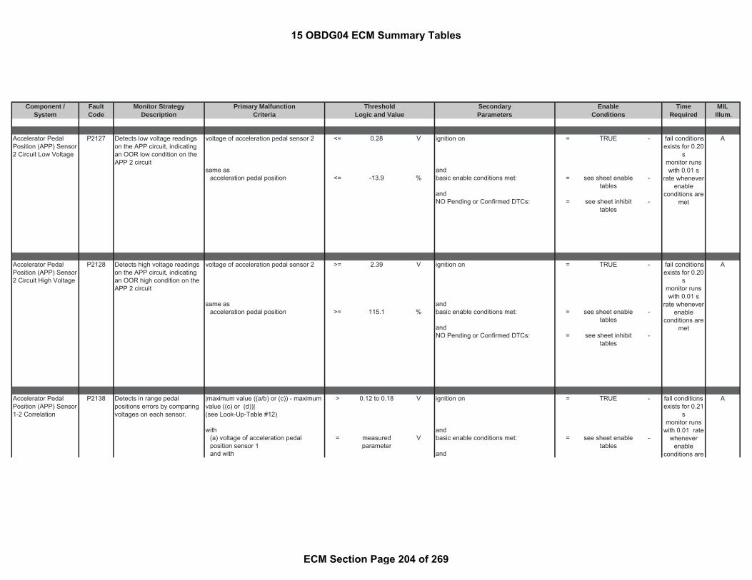
Component / Fault Monitor Strategy Primary Malfunction Secondary Time MILSystem Code Description Criteria Parameters Required Illum.
Threshold EnableLogic and Value Conditions
Accelerator PedalPosition (APP) Sensor2 Circuit Low Voltage
P2127 Detects low voltage readingson the APP circuit, indicatingan OOR low condition on theAPP 2 circuit
voltage of acceleration pedal sensor 2 <= 0.28 V ignition on = TRUE - A
same as andacceleration pedal position <= -13.9 % basic enable conditions met: = see sheet enable
tables-
andNO Pending or Confirmed DTCs: = see sheet inhibit
tables-
Accelerator PedalPosition (APP) Sensor2 Circuit High Voltage
P2128 Detects high voltage readingson the APP circuit, indicatingan OOR high condition on theAPP 2 circuit
voltage of acceleration pedal sensor 2 >= 2.39 V ignition on = TRUE - A
same as andacceleration pedal position >= 115.1 % basic enable conditions met: = see sheet enable
tables-
andNO Pending or Confirmed DTCs: = see sheet inhibit
tables-
Accelerator PedalPosition (APP) Sensor1-2 Correlation
P2138 Detects in range pedalpositions errors by comparingvoltages on each sensor.
|maximum value ((a/b) or (c)) - maximumvalue ((c) or (d))|(see Look-Up-Table #12)
> 0.12 to 0.18 V ignition on = TRUE - A
with and(a) voltage of acceleration pedalposition sensor 1
= measuredparameter
V basic enable conditions met: = see sheet enabletables
-
and with and
fail conditionsexists for 0.20
smonitor runswith 0.01 s
rate wheneverenable
conditions aremet
fail conditionsexists for 0.20
smonitor runswith 0.01 s
rate wheneverenable
conditions aremet
fail conditionsexists for 0.21
smonitor runs
with 0.01 ratewhenever
enableconditions are
15 OBDG04 ECM Summary Tables
ECM Section Page 204 of 269

Component / Fault Monitor Strategy Primary Malfunction Secondary Time MILSystem Code Description Criteria Parameters Required Illum.
Threshold EnableLogic and Value Conditions
(b) factor between sensor raw values = 2.00 - NO Pending or Confirmed DTCs: = see sheet inhibittables
-
and with(c) minimum voltage = 0.45 Vand with(d) redundant voltage of accelerationpedal (from pedal position sensor 2)
= calculatedparameter
-
Injector PositiveVoltage Control CircuitGroup 1
P2146 ECM Electronic out-put drivercircuitry determines if faults(open/short/no load) exist oninjector charging bank #1.
Voltage high during driver off state(indicates short to power, short toground, or open circuit)
= Short to power: ≤0.5 Ω impedancebetween signaland controllerpower
Open Circuit: ≥200 K Ωimpedancebetween ECU pinand load signaland controllerground
Short to ground: ≤ 0.5 Ωimpedancebetween signaland controllerground
- Engine Running (see parameterdefinition)
= TRUE - A
andfuel system status = no fuel cut off -
met
fail conditionsexists formore than
0.04 smonitor runswith 0.01 s
rate wheneverenable
conditions aremet
15 OBDG04 ECM Summary Tables
ECM Section Page 205 of 269

Component / Fault Monitor Strategy Primary Malfunction Secondary Time MILSystem Code Description Criteria Parameters Required Illum.
Threshold EnableLogic and Value Conditions
Injector PositiveVoltage Control CircuitGroup 2
P2149 ECM Electronic out-put drivercircuitry determines if faults(open/short/no load) exist oninjector charging bank #2.
Voltage high during driver off state(indicates short to power, short toground, or open circuit)
= Short to power: ≤0.5 Ω impedancebetween signaland controllerpower
Open Circuit: ≥200 K Ωimpedancebetween ECU pinand load signaland controllerground
Short to ground: ≤ 0.5 Ωimpedancebetween signaland controllerground
- Engine Running (see parameterdefinition)
= TRUE - A
andfuel system status = no fuel cut off -
Reductant tank heatershort circuit
P214F a >= b = TRUE - ignition switch on = TRUE - B
with and(a) maximum conductance of the ureatank heater
= measuredparameter
1/Ohm urea tank heater powerstage on = TRUE -
and with and(b) maximum tolerance threshold of theconductance for the urea tank heater
= 0.62 1/Ohm battery voltage >= 11.00 V
andbattery voltage <= 655.34 V
fail conditionsexists formore than
0.04 smonitor runswith 0.01 s
rate wheneverenable
conditions aremet
Detects a tank heater shortcircuit by detecting highconductance in the heater
fail conditionsexists for0.001 s
monitor runsonce per tripwith 0.001 s
rate wheneverenable
conditions aremet
15 OBDG04 ECM Summary Tables
ECM Section Page 206 of 269

Component / Fault Monitor Strategy Primary Malfunction Secondary Time MILSystem Code Description Criteria Parameters Required Illum.
Threshold EnableLogic and Value Conditions
andengine off time >= 12.00 secandurea tank temperature <= 41.96 °Cand(
conductance of the urea tank heater issteady or falling
= TRUE -
fortime > 20.00 sec
orheater activation time >= 50.00 sec)
andbasic enable conditions met: = see sheet enable
tables-
andNO Pending or Confirmed DTCs: = see sheet inhibit
tables-
Intake Air TempSensor (IAT) 1 / 2Correlation
P2199 Detects biased HumidityTemperature Sensor or MAFIntake Air Temperature Sensorby comparing the measuredtemperatures at start.
Path 1: minimum engine-off time >= 28800.00 sec B
andengine off time is valid = TRUE -
|(a) - (b)| (see Look-Up-Table #2) > 20 to 999 °C andwhere ambient air temperature > -60.04 °C(a) captured intake air temperature atstart
= measuredparameter
- and
and ignition on (see parameter definition) = TRUE -(b) captured humidity temperature atstart
= measuredparameter
- for
time > 0.01 secandengine post drive/ afterun = FALSE -anddiagnostic performed in current drivecycle
= FALSE -
fail conditionsexists for 0.1
smonitor runsonce per trip
with 0.1 s ratewhenever
enableconditions are
met
15 OBDG04 ECM Summary Tables
ECM Section Page 207 of 269

Component / Fault Monitor Strategy Primary Malfunction Secondary Time MILSystem Code Description Criteria Parameters Required Illum.
Threshold EnableLogic and Value Conditions
andbasic enable conditions met: = see sheet enable
tables-
andNO Pending or Confirmed DTCs: = see sheet inhibit
tables-
Reductant LevelSensor 2 Circuit Low
P21AA CAN message: Discrete levelsensor level 2 short to grounderror
Reductant Tank Level 2 Error Status = 1 - ignition on = TRUE - B
( tank level sensor 2 voltage directlymeasured after a test impulse wasapplied )
< ( 0.17 ) V battery voltage > 8 V
basic enable conditions met: = see sheet enabletables
-
Reductant LevelSensor 2 Circuit High
P21AB Path 1: A
CAN message: Discrete levelsensor 2 open load error
Reductant Tank Level 2 Error Status = 3 - ignition on = TRUE -
( measured tank level sensor 2 voltageafter 1.5 ms since a test impulse wasapplied )
> ( 3.56 ) V battery voltage > 8 V
( measured tank level sensor 2 voltageafter 1.5 ms since a test impulse wasapplied )
< ( 4.74 ) V basic enable conditions met: = see sheet enabletables
-
Path 2:
fail conditionsexists for
more than 3sec.
monitor runswith 0.01 s
rate wheneverenable
conditions aremet
fail conditionsexists for
more than 3sec
monitor runswith 1 s ratewhenever
enableconditions are
met
fail conditions
15 OBDG04 ECM Summary Tables
ECM Section Page 208 of 269

Component / Fault Monitor Strategy Primary Malfunction Secondary Time MILSystem Code Description Criteria Parameters Required Illum.
Threshold EnableLogic and Value Conditions
CAN message: Discrete levelsensor 2 short to battery error
Reductant Tank Level 2 Error Status = 2 - ignition on = TRUE -
( measured tank level sensor 2 voltageafter 1.5 ms since a test impulse wasapplied )
> ( 4.74 ) V battery voltage > 8 V
basic enable conditions met: = see sheet enabletables
-
Reductant LevelSensor 3 Circuit Low
P21AF CAN message: Discrete levelsensor level 3 short to grounderror
Reductant Tank Level 3 Error Status = 1 - ignition on = TRUE - B
( tank level sensor 3 voltage directlymeasured after a test impulse wasapplied )
< ( 0.17 ) V battery voltage > 8 V
basic enable conditions met: = see sheet enabletables
-
Reductant LevelSensor 3 Circuit High
P21B0 Path 1: A
CAN message: Discrete levelsensor 3 open load error
Reductant Tank Level 3 Error Status = 3 - ignition on = TRUE -
( measured tank level sensor 3 voltageafter 1.5 ms since a test impulse wasapplied )
> ( 3.56 ) V battery voltage > 8 V
( measured tank level sensor 3 voltageafter 1.5 ms since a test impulse wasapplied )
< ( 4.74 ) V basic enable conditions met: = see sheet enabletables
-
exists formore than 3
secmonitor runswith 1 s ratewhenever
enableconditions are
met
fail conditionsexists for
more than 3sec.
monitor runswith 0.01 s
rate wheneverenable
conditions aremet
fail conditionsexists for
more than 3sec
monitor runswith 1 s ratewhenever
enableconditions are
met
15 OBDG04 ECM Summary Tables
ECM Section Page 209 of 269

Component / Fault Monitor Strategy Primary Malfunction Secondary Time MILSystem Code Description Criteria Parameters Required Illum.
Threshold EnableLogic and Value Conditions
Path 2:CAN message: Discrete levelsensor 3 short to battery error
Reductant Tank Level 3 Error Status = 2 - ignition on = TRUE -
( measured tank level sensor 3 voltageafter 1.5 ms since a test impulse wasapplied )
> ( 4.74 ) V battery voltage > 8 V
basic enable conditions met: = see sheet enabletables
-
Reductant tank heateropen circuit
P21DD a <= b = TRUE - ignition switch on = TRUE - B
with and(a) maximum conductance of the ureatank heater
= measuredparameter
1/Ohm urea tank heater powerstage on = TRUE -
and with and(b) minimum tolerance threshold of theconductance for the urea tank heater
= 0.27 1/Ohm battery voltage >= 11.00 V
andbattery voltage <= 655.34 Vandengine off time >= 300.00 secandurea tank temperature <= 41.96 °Cand(
conductance of the urea tank heater issteady or falling
= TRUE -
fortime > 400.00 sec
orheater activation time >= 50.00 sec
fail conditionsexists for
more than 3sec
monitor runswith 1 s ratewhenever
enableconditions are
met
Detects a tank heater opencircuit by detecting lowconductance in the heater
fail conditionsexists for0.001 s
monitor runsonce per tripwith 0.001 s
rate wheneverenable
conditions aremet
15 OBDG04 ECM Summary Tables
ECM Section Page 210 of 269

Component / Fault Monitor Strategy Primary Malfunction Secondary Time MILSystem Code Description Criteria Parameters Required Illum.
Threshold EnableLogic and Value Conditions
)andbasic enable conditions met: = see sheet enable
tables-
andNO Pending or Confirmed DTCs: = see sheet inhibit
tables-
NOx Sensor CircuitBank 1 Sensor 1
P2200 Detects a failure when opencircuit status message fromNOx sensor is receivedcontinuously for a time period
Open circuit NOx signal error = TRUE - following conditions for time > 10.00 sec A
battery voltage >= 11.00 Vbattery voltage <= 655.34 VSCR upstream temperature >= 99.96 °CSCR upstream temperature <= 599.96 °CEngine Running = TRUE -
for time >= 20.00 secCan Bus Initialized ( CAN Bus is Active)
= TRUE -
consisting of:ignition on = TRUE -
for time >= 3 secbattery voltage > 9.8 Vbattery voltage < 655.34 V
Upstream NOx sensor dewpointachieved (please see the definition)
= TRUE -
NO Pending or Confirmed DTCs: = see sheet inhibittables
-
basic enable conditions met: = see sheet enabletables
-
Detects a failure when shortcircuit status message fromNOx sensor is receivedcontinuously for a time period
Short Circuit NOx signal error = TRUE - following conditions for time > 10.00 sec
battery voltage >= 11.00 Vbattery voltage <= 655.34 V
fail conditionsexists for
more than 13sec.
monitor runswith 0.01 s
rate wheneverenable
conditions aremet
fail conditionsexists for
more than 13sec.
monitor runswith 0.01 s
rate whenever
15 OBDG04 ECM Summary Tables
ECM Section Page 211 of 269

Component / Fault Monitor Strategy Primary Malfunction Secondary Time MILSystem Code Description Criteria Parameters Required Illum.
Threshold EnableLogic and Value Conditions
SCR upstream temperature >= 99.96 °CSCR upstream temperature <= 599.96 °CStatus of Start stop condition. ( QuickKey Cycle Delay ) ( 20 sec )
= TRUE -
Engine Running = TRUE -for time >= 20.00 sec
Can Bus Initialized ( CAN Bus is Active)
= TRUE -
consisting of:ignition on = TRUE -
for time >= 3 secbattery voltage > 9.8 Vbattery voltage < 655.34 V
Upstream NOx sensor dewpointachieved (please see the definition)
= TRUE -
NO Pending or Confirmed DTCs: = see sheet inhibittables
-
basic enable conditions met: = see sheet enabletables
-
N0x Sensor CircuitHigh Bank 1 Sensor 1
P2203 Detects an out of range highfault of the upstream NoXSensor
NOx sensor signal (raw informationreceived via CAN from NOx sensor)
> 2400.00 ppm NOx sensor 1 ready status (seeparameter definition)
= TRUE - B
Valid NOx signal from CAN is received(no NOx sensor communication failures)
= TRUE -
Engine Running (see parameterdefinition)
= TRUE -
for time > 20.00 secN0x Sensor CircuitLow Bank 1 Sensor 1
P2202 Detects an out of range lowfault of the upstream NoXSensor
NOx sensor signal (raw informationreceived via CAN from NOx sensor)
< -90.00 ppm and
Injection Quantity > 4.00 mm^3/rev
orUpstream NOx sensor dewpointachieved (please see the definition)
= TRUE -
for time > 300.00 sec
enableconditions are
met
fault exists formore than 10sec; monitorruns at 0.1 swhen enable
conditions aremet
15 OBDG04 ECM Summary Tables
ECM Section Page 212 of 269
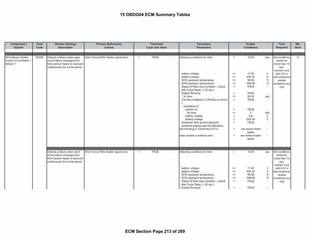
Component / Fault Monitor Strategy Primary Malfunction Secondary Time MILSystem Code Description Criteria Parameters Required Illum.
Threshold EnableLogic and Value Conditions
NOx Sensor HeaterControl Circuit Bank 1Sensor 1
P2205 Detects a failure when opencircuit status message fromNOx sensor heater is receivedcontinuously for a time period
Open Circuit NOx Heater signal error = TRUE - following conditions for time > 10.00 sec A
battery voltage >= 11.00 Vbattery voltage <= 655.34 VSCR upstream temperature >= 99.96 °CSCR upstream temperature <= 599.96 °CStatus of Start stop condition. ( QuickKey Cycle Delay ) ( 20 sec )
= TRUE -
Engine Running = TRUE -for time >= 20.00 sec
Can Bus Initialized ( CAN Bus is Active)
= TRUE -
consisting of:ignition on = TRUE -
for time >= 3 secbattery voltage > 9.8 Vbattery voltage < 655.34 V
Upstream NOx sensor dewpointachieved (please see the definition)
= TRUE -
NO Pending or Confirmed DTCs: = see sheet inhibittables
-
basic enable conditions met: = see sheet enabletables
-
Detects a failure when shortcircuit status message fromNOx sensor heater is receivedcontinuously for a time period
Short Circuit NOx heater signal error = TRUE - following conditions for time > 10.00 sec
battery voltage >= 11.00 Vbattery voltage <= 655.34 VSCR upstream temperature >= 99.96 °CSCR upstream temperature <= 599.96 °CStatus of Start stop condition. ( QuickKey Cycle Delay ) ( 20 sec )
= TRUE -
Engine Running = TRUE -
fail conditionsexists for
more than 13sec.
monitor runswith 0.01 s
rate wheneverenable
conditions aremet
fail conditionsexists for
more than 13sec.
monitor runswith 0.01 s
rate wheneverenable
conditions aremet
15 OBDG04 ECM Summary Tables
ECM Section Page 213 of 269

Component / Fault Monitor Strategy Primary Malfunction Secondary Time MILSystem Code Description Criteria Parameters Required Illum.
Threshold EnableLogic and Value Conditions
for time >= 20.00 secCan Bus Initialized ( CAN Bus is Active)
= TRUE -
consisting of:ignition on = TRUE -
for time >= 3 secbattery voltage > 9.8 Vbattery voltage < 655.34 V
Upstream NOx sensor dewpointachieved (please see the definition)
= TRUE -
NO Pending or Confirmed DTCs: = see sheet inhibittables
-
basic enable conditions met: = see sheet enabletables
-
NOx HeaterPerformance Bank 1Sensor 1
P2209 Monitoring of the upstreamNOx sensor signal readiness
Upstream NOx sensor heatertemperature has reached setpoint
= FALSE - ( B
battery voltage >= 1.00 Vandbattery voltage <= 655.34 VandOxidation Catalyst upstreamtemperature
>= 99.96 °C
andOxidation Catalyst upstreamtemperature
<= 599.96 °C
andEngine running = TRUE -
for time > 20.00 secandUpstream NOx sensor dewpointachieved (please see the definition)
= TRUE -
)for time > 160 sec
andbasic enable conditions met: = see sheet enable
tables-
No Pending or Confirmed DTC = see sheet inhibittables
-
fault exists formore than 1event when
dewpoint endis reached;
monitor runsat 0.02 s
when enableconditions are
met
15 OBDG04 ECM Summary Tables
ECM Section Page 214 of 269

Component / Fault Monitor Strategy Primary Malfunction Secondary Time MILSystem Code Description Criteria Parameters Required Illum.
Threshold EnableLogic and Value Conditions
Reductant pressureline heater open circuit
P221C a <= b = TRUE - ignition switch on = TRUE - B
with and(a) conductance of the urea pressureline heater
= measuredparameter
1/Ohm urea pressure line heater powerstage on = TRUE -
and with and(b) minimum tolerance threshold of theconductance for the urea pressure lineheater
= 0.35 1/Ohm battery voltage >= 11.00 V
andbattery voltage <= 655.34 Vandengine off time >= 300.00 secandheater activation time >= 11.50 secandbasic enable conditions met: = see sheet enable
tables-
andNO Pending or Confirmed DTCs: = see sheet inhibit
tables-
Reductant pressureline heater short circuit
P221D a >= b = TRUE - ignition switch on = TRUE - B
with and(a) conductance of the urea pressureline heater
= measuredparameter
1/Ohm urea pressure line heater powerstage on = TRUE -
and with and(b) maximum tolerance threshold of theconductance for the urea pressure lineheater
= 0.78 1/Ohm battery voltage >= 11.00 V
andbattery voltage <= 655.34 Vandengine off time >= 300.00 secandheater activation time >= 11.50 secand
Detects a pressure line heateropen circuit by detecting lowconductance in the heater
fail conditionsexists for 3 smonitor runs
with 0.1 s ratewhenever
enableconditions are
met
Detects a pressure line heatershort circuit by detecting highconductance in the heater
fail conditionsexists for 3 smonitor runs
with 0.1 s ratewhenever
enableconditions are
met
15 OBDG04 ECM Summary Tables
ECM Section Page 215 of 269

Component / Fault Monitor Strategy Primary Malfunction Secondary Time MILSystem Code Description Criteria Parameters Required Illum.
Threshold EnableLogic and Value Conditions
basic enable conditions met: = see sheet enabletables
-
andNO Pending or Confirmed DTCs: = see sheet inhibit
tables-
Reductant supplymodule heater opencircuit
P221E a <= b = TRUE - ignition switch on = TRUE - B
with and(a) maximum conductance of thesupply module heater
= measuredparameter
1/Ohm supply module heater powerstage on = TRUE -
and with and(b) minimum tolerance threshold of theconductance for the supply moduleheater
= 0.14 1/Ohm battery voltage >= 11.00 V
andbattery voltage <= 655.34 Vandengine off time >= 300.00 secand(
conductance of the urea supply moduleheater is steady or falling
= TRUE -
fortime > 50.00 sec
orheater activation time >= 50.00 sec
)andbasic enable conditions met: = see sheet enable
tables-
andNO Pending or Confirmed DTCs: = see sheet inhibit
tables-
Reductant supplymodule heater shortcircuit
P221F a >= b = TRUE - ignition switch on = TRUE - B
with and
Detects a supply moduleheater open circuit bydetecting low conductance inthe heater
fail conditionsexists for0.001 s
monitor runsonce per tripwith 0.001 s
rate wheneverenable
conditions aremet
Detects a supply moduleheater short circuit bydetecting high conductance inthe heater
fail conditionsexists for0.001 s
monitor runs
15 OBDG04 ECM Summary Tables
ECM Section Page 216 of 269

Component / Fault Monitor Strategy Primary Malfunction Secondary Time MILSystem Code Description Criteria Parameters Required Illum.
Threshold EnableLogic and Value Conditions
(a) maximum conductance of thesupply module heater
= measuredparameter
1/Ohm supply module heater powerstage on = TRUE -
and with and(b) maximum tolerance threshold of theconductance for the supply moduleheater
= 0.46 1/Ohm battery voltage >= 11.00 V
andbattery voltage <= 655.34 Vandengine off time >= 300.00 secand(
conductance of the urea supply moduleheater is steady or falling
= TRUE -
fortime > 50.00 sec
orheater activation time >= 50.00 sec
)andbasic enable conditions met: = see sheet enable
tables-
andNO Pending or Confirmed DTCs: = see sheet inhibit
tables-
Barometric PressureSensor "A" Circuit Low
P2228 Detects low voltage readingson the ECM internal BAROcircuit, indicating an OOR lowcondition on the BARO circuit.
voltage of barometric pressure sensor <= 1.97 V ignition on = TRUE - B
same as andambient pressure <= 50.00 kPa NO Pending or Confirmed DTCs: = see sheet inhibit
tables-
andbasic enable conditions met: = see sheet enable
tables-
once per tripwith 0.001 s
rate wheneverenable
conditions aremet
fail conditionsexists for 1.5
smonitor runs
0.1 s ratewhenever
enableconditions are
met
15 OBDG04 ECM Summary Tables
ECM Section Page 217 of 269
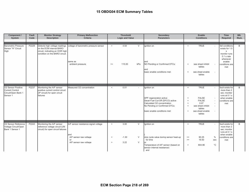
Component / Fault Monitor Strategy Primary Malfunction Secondary Time MILSystem Code Description Criteria Parameters Required Illum.
Threshold EnableLogic and Value Conditions
Barometric PressureSensor "A" CircuitHigh
P2229 Detects high voltage readingson the ECM internal BAROcircuit, indicating an OOR highcondition on the BARO circuit.
voltage of barometric pressure sensor > 4.54 V ignition on = TRUE - B
same as andambient pressure >= 115.00 kPa NO Pending or Confirmed DTCs: = see sheet inhibit
tables-
andbasic enable conditions met: = see sheet enable
tables-
O2 Sensor PositiveCurrent ControlCircuit/Open Bank 1Sensor 1
P2237 Monitoring the A/F sensorpositive current control circuit(IP circuit) for open circuitfailures
Measured O2 concentration < 0.01 - Ignition on = TRUE - B
DPF regeneration active = FALSE -Decel Fuel Cut-Off (DFCO) active = FALSE -Calculated O2 concentration > 0.07 -No Pending or Confirmed DTCs: = see sheet inhibit
tables-
basic enable conditions met: = see sheet enabletables
-
O2 Sensor ReferenceVoltage Circuit/OpenBank 1 Sensor 1
P2243 Monitoring the A/F sensorreference voltage circuit (UNcircuit) for open circuit failures
A/F sensor resistance signal voltage > 3.00 V Ignition on = TRUE - B
and (A/F sensor raw voltage < -1.30 V duty cycle value during sensor heat-up >= 90.25 %or for time >= 19.50 secA/F sensor raw voltage > 3.22 V or
Temperature of A/F sensor (based onsensor internal resistance)
> 804.96 °C
and
fail conditionsexists for 1.5
smonitor runs
0.1 s ratewhenever
enableconditions are
met
fault exists formore than 2sec; monitorruns at 0.1 swhen enable
conditions aremet
fault exists formore than 2sec; monitorruns at 0.1 swhen enable
conditions aremet
15 OBDG04 ECM Summary Tables
ECM Section Page 218 of 269

Component / Fault Monitor Strategy Primary Malfunction Secondary Time MILSystem Code Description Criteria Parameters Required Illum.
Threshold EnableLogic and Value Conditions
Status bit for valid A/F sensor innerResistance (see parameter definitiontable)
= TRUE -
)Decel Fuel Cut-Off Active (DFCO) = FALSE -Battery voltage > 11.00 VA/F sensor error status bit (seeparameter definition table)
= FALSE -
No permanent heater control deviationerror present (P0053)
= TRUE
andStatus bit indicates if the ramp up for theA/F sensor heater is released [True =heater ramp up is released, False =heater ramp up is deactivated]
= TRUE
for time > 37.00 secorA/F sensor temperature > 805.96 °CA/F sensor temperature < 823.96 °CNo Pending or Confirmed DTCs: = see sheet inhibit
tables-
basic enable conditions met: = see sheet enabletables
-
O2 Sensor NegativeCurrent ControlCircuit/Open Bank 1Sensor 1
P2251 Monitoring the A/F sensornegative current control circuit(VM circuit) for open circuitfailures
A/F sensor resistance signal voltage > 3.00 V Ignition on = TRUE - B
and (A/F sensor raw voltage > -0.20 V duty cycle value during sensor heat-up >= 90.25 %or for time >= 19.50 secA/F sensor raw voltage < 0.20 V or
Temperature of A/F sensor (based onsensor internal resistance)
> 804.96 °C
andStatus bit for valid A/F sensor innerResistance (see parameter definitiontable)
= TRUE -
)Decel Fuel Cut-Off Active (DFCO) = FALSE -Battery voltage > 11.00 V
fault exists formore than 2sec; monitorruns at 0.1 swhen enable
conditions aremet
15 OBDG04 ECM Summary Tables
ECM Section Page 219 of 269

Component / Fault Monitor Strategy Primary Malfunction Secondary Time MILSystem Code Description Criteria Parameters Required Illum.
Threshold EnableLogic and Value Conditions
A/F sensor error status bit (seeparameter definition table)
= FALSE -
No permanent heater control deviationerror present (P0053)
= TRUE
andStatus bit indicates if the ramp up for theA/F sensor heater is released [True =heater ramp up is released, False =heater ramp up is deactivated]
= TRUE
for time > 37.00 secorA/F sensor temperature > 805.96 °CA/F sensor temperature < 823.96 °CNo Pending or Confirmed DTCs: = see sheet inhibit
tables-
basic enable conditions met: = see sheet enabletables
-
Turbo Boost SystemPerformance
P2263 Detects if the Turbocharger isseverely over or underboosting based on controldeviation
Path 1: following conditions for time: > 0.50 sec A
control deviation of the boost pressurecalculated out of difference betweendesired and actual value
> (g) * (h) - ( = FALSE -
with VNT turbo charger offset adaptationactive
= FALSE -
(g) the upper limit (see Look-Up-Table#60)
= 35.0 to 85.0 kPa and
(h) correction factor (see Look-Up-Table #85)
= 0.85 to 1.0 factor turbo charger (VNT) wiping is active = FALSE -
andabsolute filtered gradient of boostpressure setpoint, PCR_pDesVal ,calculated over a time dT constitutesthe third condition for detecting thesteady state
< 5.00 kPa
andinjection Quantity >= 120.00 mm^3/r
ev
fail conditionsexists for 15 s
testperformed
continuously0.01 s rate
15 OBDG04 ECM Summary Tables
ECM Section Page 220 of 269

Component / Fault Monitor Strategy Primary Malfunction Secondary Time MILSystem Code Description Criteria Parameters Required Illum.
Threshold EnableLogic and Value Conditions
injection Quantity <= 170.00 mm^3/rev
andengine Speed >= 2250.00 rpmengine Speed <= 4000.00 rpmandparticulate filter regeneration = FALSE -andNO Pending or Confirmed DTCs: see sheet inhibit
tables-
)andbasic enable conditions met: = see sheet enable
tables
Path 2: following conditions for time: > 0.50 seccontrol deviation of the boost pressurecalculated out of difference betweendesired and actual value
< (i) * (j) - (
with VNT turbo charger offset adaptationactive
= FALSE -
(i) the upper limit (see Look-Up-Table#59)
= -55.0 to -25.0 kPa and
(j) correction factor (see Look-Up-Table #84)
= 1.00 to 1.25 factor turbo charger (VNT) wiping is active = FALSE -
andabsolute filtered gradient of boostpressure setpoint, PCR_pDesVal ,calculated over a time dT constitutesthe third condition for detecting thesteady state
< 7.50 kPa
andinjection Quantity >= 120.00 mm^3/r
evinjection Quantity <= 170.00 mm^3/r
evandengine Speed >= 2250.00 rpmengine Speed <= 4000.00 rpmand
particulate filter regeneration = FALSE -
fail conditionsexists for 15 s
testperformed
continuously0.01 s rate
15 OBDG04 ECM Summary Tables
ECM Section Page 221 of 269
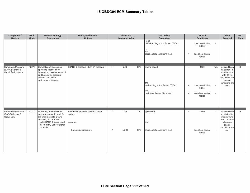
Component / Fault Monitor Strategy Primary Malfunction Secondary Time MILSystem Code Description Criteria Parameters Required Illum.
Threshold EnableLogic and Value Conditions
andNO Pending or Confirmed DTCs: see sheet inhibit
tables-
)andbasic enable conditions met: = see sheet enable
tables
Barometric Pressure(BARO) Sensor 2Circuit Performance
P227B Correlation at low engineoperating speeds of thebarometric pressure sensor 1and barometric pressuresensor 2 for sensorperformance failures
| BARO 2 pressure - BARO1 pressure | > 7.50 kPa engine speed < 1500 rpm B
andNo Pending or Confirmed DTCs: = see sheet inhibit
tables-
andbasic enable conditions met: = see sheet enable
tables-
Barometric Pressure(BARO) Sensor 2Circuit Low
P227C Monitoring the barometricpressure sensor 2 circuit forthe short circuit to groundindicating an OOR low
barometric pressure sensor 2 circuitvoltage
< 1.96 V Ignition on = TRUE - B
Note: BARO 2 signal usedfor Humidity Sensor signalcorrection
same as and
barometric pressure 2 < 50.00 kPa basic enable conditions met: = see sheet enabletables
-
fail conditionsexists for 7 smonitor runswith 0.01 s
rate wheneverenable
conditions aremet
fail conditionsexists for 5 smonitor runs
with 0.1 s ratewhenever
enableconditions are
met
15 OBDG04 ECM Summary Tables
ECM Section Page 222 of 269

Component / Fault Monitor Strategy Primary Malfunction Secondary Time MILSystem Code Description Criteria Parameters Required Illum.
Threshold EnableLogic and Value Conditions
Barometric Pressure(BARO) Sensor 2Circuit High
P227D Monitoring the barometricpressure sensor 2 circuit forshort circuit to battery andopen circuit indicating an OORhigh
barometric pressure sensor 2 circuitvoltage
> 4.50 V Ignition on = TRUE -- B
Note: BARO 2 signal usedfor Humidity Sensor signalcorrection
same as and
barometric pressure 2 > 115.00 kPa basic enable conditions met: = see sheet enabletables
-
Fuel PressureRegulator 2 ControlCircuit
P2294 Diagnoses the Fuel PressureRegulator 2 low side drivercircuit for circuit faults.
Voltage low during driver off state(indicates open circuit)
= Open Circuit: ≥200 K Ωimpedancebetween ECU pinand load signaland controllerground
- ignition on = TRUE - A
andBattery voltage > 10.50 V
fortime > 3.00 sec
andbasic enable conditions met: = see sheet enable
tables-
andNO Pending or Confirmed DTCs = see sheet inhibit
tables-
fail conditionsexists for 5 smonitor runs
with 0.1 s ratewhenever
enableconditions are
met
fail conditionsexists for 0.28
smonitor runswith 0.01 s
rate wheneverenable
conditions aremet
15 OBDG04 ECM Summary Tables
ECM Section Page 223 of 269

Component / Fault Monitor Strategy Primary Malfunction Secondary Time MILSystem Code Description Criteria Parameters Required Illum.
Threshold EnableLogic and Value Conditions
Electronic power stage circuitrydetermines over temperature on the fuelpressure regulator 2 control circuit.
ignition on = TRUE -
andBattery voltage > 10.50 V
fortime > 3.00 sec
andbasic enable conditions met: = see sheet enable
tables-
andNO Pending or Confirmed DTCs = see sheet inhibit
tables-
Fuel PressureRegulator 2 ControlCircuit Low Voltage
P2295 Diagnoses the Fuel PressureRegulator 2 low side drivercircuit for circuit faults.
Voltage low during driver off state(indicates short-to-ground)
= Short to ground: 0.5
impedancebetween signaland controllerground
- ignition on = TRUE - A
andBattery voltage > 10.50 V
fortime > 3.00 sec
andbasic enable conditions met: = see sheet enable
tables-
andNO Pending or Confirmed DTCs = see sheet inhibit
tables-
Fuel PressureRegulator 2 ControlCircuit High Voltage
P2296 Diagnoses the Fuel PressureRegulator 2 low side drivercircuit for circuit faults.
Voltage high during driver on state(indicates short to power)
= Short to power: ≤ 0.5 Ωimpedancebetween signaland controllerpower
- ignition on = TRUE - A
fail conditionsexists for 0.28
smonitor runswith 0.01 s
rate wheneverenable
conditions aremet
fail conditionsexists for 0.05
smonitor runswith 0.01 s
rate wheneverenable
conditions aremet
fail conditionsexists for 0.28
smonitor runswith 0.01 s
rate wheneverenable
15 OBDG04 ECM Summary Tables
ECM Section Page 224 of 269

Component / Fault Monitor Strategy Primary Malfunction Secondary Time MILSystem Code Description Criteria Parameters Required Illum.
Threshold EnableLogic and Value Conditions
andBattery voltage > 10.50 V
fortime > 3.00 sec
andbasic enable conditions met: = see sheet enable
tables-
andNO Pending or Confirmed DTCs = see sheet inhibit
tables-
O2 Sensor Out ofRange DuringDeceleration Bank 1Sensor 1
P2297 A/Fsensor signal monitoring inDFCO, which monitors adeviation of the raw A/Fsensor signal and calculatedsensor signal.
difference between filtered calculatedA/F concentration and measured A/Fsensor concentration -> refer to Column2 in the table (see Look-Up-Table #50)
> 0.06 to 0.07 - following conditions met for Integrated airmass:
> 80 g B
Note: Calculated A/F concentration iscalculated as a function of InjectionQuantity and Air Mass per cylinder(which is calculated on MAF sensorand EGR)
Engine speed ->refer to the Column 2in the table (see Look-Up-Table #47)
< 2700 to 4500 rpm
Injection quantity -> refer to the Column2 in the table (see Look-Up-Table #49)
> -1.0 to 16 mm^3/rev
Injection quantity -> refer to the Column2 in the table (see Look-Up-Table #48)
< 0.4 to 44 mm^3/rev
Air mass per cylinder ->refer to theColumn 12in the table (see Look-Up-Table #46)
> 0.09 to 0.25 g/rev
Air mass per cylinder ->refer to theColumn 2 in the table (see Look-Up-Table #45)
< 0.25 to 0.45 g/rev
DPF regeneration not active = TRUE -Post injection is not active (postinjection only active during cold startcatalyst heating or DPF regeneration)
= TRUE -
Temperature of A/F sensor (based onsensor internal resistance)
=< 805.96 °C
Temperature of A/F sensor (based onsensor internal resistance)
>= 823.96 °C
fail conditionsexists for 0.1
smonitor runswith 0.02 s
rate wheneverenable
conditions aremet
conditions aremet
15 OBDG04 ECM Summary Tables
ECM Section Page 225 of 269

Component / Fault Monitor Strategy Primary Malfunction Secondary Time MILSystem Code Description Criteria Parameters Required Illum.
Threshold EnableLogic and Value Conditions
Absolute change in actual calculatedO2 concentration
< 0.02 -
for time >= 1.50 secFuel volume in fuel tank >= 0.00 lBattery voltage >= 11.00 VDecel Fuel Cut-Off (DFCO) = TRUE -NO Pending or Confirmed DTCs: = see sheet inhibit
tables-
basic enable conditions met: = see sheet enabletables
-
A/Fsensor signal monitoring inDFCO, which monitors adeviation of the raw A/Fsensor signal and calculatedsensor signal.
difference between measured A/F sensorconcentration and filtered calculated A/Fconcentration -> refer to Column 2 in thetable (see Look-Up-Table #51)
> 0.04 to 0.07 - following conditions met for Integrated airmass:
> 80 g
Note: Calculated A/F concentration iscalculated as a function of InjectionQuantity and Air Mass per cylinder(which is calculated on MAF sensorand EGR)
Engine speed ->refer to the Column 2in the table (see Look-Up-Table #47)
< 2700 to 4500 rpm
Injection quantity -> refer to the Column2 in the table (see Look-Up-Table #49)
> -1.0 to 16 mm^3/rev
Injection quantity -> refer to the Column2 in the table (see Look-Up-Table #48)
< 0.4 to 44 mm^3/rev
Air mass per cylinder ->refer to theColumn 12in the table (see Look-Up-Table #46)
> 0.09 to 0.25 g/rev
Air mass per cylinder ->refer to theColumn 2 in the table (see Look-Up-Table #45)
< 0.25 to 0.45 g/rev
DPF regeneration not active = TRUE -Post injection is not active (postinjection only active during cold startcatalyst heating or DPF regeneration)
= TRUE -
Temperature of A/F sensor (based onsensor internal resistance)
=< 805.96 °C
Temperature of A/F sensor (based onsensor internal resistance)
>= 823.96 °C
fail conditionsexists for 0.1
smonitor runswith 0.02 s
rate wheneverenable
conditions aremet
15 OBDG04 ECM Summary Tables
ECM Section Page 226 of 269

Component / Fault Monitor Strategy Primary Malfunction Secondary Time MILSystem Code Description Criteria Parameters Required Illum.
Threshold EnableLogic and Value Conditions
Absolute change in actual calculatedO2 concentration
< 0.02 -
for time >= 1.50 secFuel volume in fuel tank >= 0.00 lBattery voltage >= 11.00 VDecel Fuel Cut-Off (DFCO) = TRUE -NO Pending or Confirmed DTCs: = see sheet inhibit
tables-
basic enable conditions met: = see sheet enabletables
-
NOx Sensor CircuitBank 1 Sensor 2
P229E Detects a failure when opencircuit status message fromdownstream NOx sensor isreceived continuously for atime period
Open circuit downstream NOx signalerror
= TRUE - following conditions for time > 10.00 sec A
battery voltage >= 11.00 Vbattery voltage <= 655.34 VSCR downstream temperature >= 99.96 °CSCR downstream temperature <= 599.96 °CEngine Running = TRUE -
for time >= 20.00 secCan Bus Initialized ( CAN Bus is Active)
= TRUE -
consisting of:ignition on = TRUE -
for time >= 3 secbattery voltage > 9.8 Vbattery voltage < 655.34 V
Downstream NOx sensor dewpointachieved (please see the definition)
= TRUE -
no pending or confirmed faults = see sheet inhibittables
-
basic enable conditions met: = see sheet enabletables
-
Downstream NOx sensor shortcircuit error via the CANmessage
Short circuit NOx signal error ofdownstream NOx sensor via CANmessage
= TRUE - following conditions for time > 10.00 sec
fail conditionsexists for
more than 13s
monitor runswith 0.1 s rate
wheneverenable
conditions aremet
fail conditionsexists for
more than 13
15 OBDG04 ECM Summary Tables
ECM Section Page 227 of 269
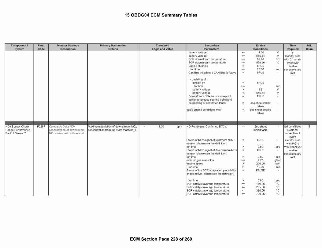
Component / Fault Monitor Strategy Primary Malfunction Secondary Time MILSystem Code Description Criteria Parameters Required Illum.
Threshold EnableLogic and Value Conditions
battery voltage >= 11.00 Vbattery voltage <= 655.34 VSCR downstream temperature >= 99.96 °CSCR downstream temperature <= 599.96 °CEngine Running = TRUE -
for time >= 20.00 secCan Bus Initialized ( CAN Bus is Active)
= TRUE -
consisting of:ignition on = TRUE -
for time >= 3 secbattery voltage > 9.8 Vbattery voltage < 655.34 V
Downstream NOx sensor dewpointachieved (please see the definition)
= TRUE -
no pending or confirmed faults = see sheet inhibittables
-
basic enable conditions met: = see sheet enabletables
-
NOx Sensor CircuitRange/PerformanceBank 1 Sensor 2
P229F Compares Delta NOxconcentration of downstreamNOx sensor with a threshold
Maximum deviation of downstream NOxconcentration from the state machine_5
< 3.00 ppm NO Pending or Confirmed DTCs: = See sheetinhibit table
- B
Status of NOx signal of upstream NOxsensor (please see the definition)
= TRUE -
for time > 0.00 secStatus of NOx signal of downstream NOxsensor (please see the definition)
= TRUE -
for time > 0.00 secexhaust gas mass flow >= 2.78 g/secengine speed > 200.00 rpm
for time > 10.00 secStatus of the SCR adaptation plausibilitycheck active (please see the definition)
= FALSE -
for time > 0.00 secSCR catalyst average temperature >= 180.06 °CSCR catalyst average temperature <= 285.06 °CSCR catalyst average temperature >= 380.06 °CSCR catalyst average temperature <= 700.06 °C
smonitor runs
with 0.1 s ratewhenever
enableconditions are
met
fail conditionsexists for
more than 1event
monitor runswith 0.01s
rate wheneverenable
conditions aremet
15 OBDG04 ECM Summary Tables
ECM Section Page 228 of 269

Component / Fault Monitor Strategy Primary Malfunction Secondary Time MILSystem Code Description Criteria Parameters Required Illum.
Threshold EnableLogic and Value Conditions
(State machine_0 : starting state andwaiting for low upstream NOx massflow / concentration
(Filtered upstream NOx mass flow < 0.03 g/secFiltered NOx concentration < 260.00 ppmExhaust mass flow message < 40.28 g/sec
for time < 2.00 sec)
State machine_1 : low upstream NOxmass flow /concentration reached
(Old State machine_0 : starting stateand waiting for low upstream NOx massflow / concentration
= TRUE -
for time >= 2.00 secFiltered upstream NOx mass flow < 0.03 g/secFiltered NOx concentration < 260.00 ppmExhaust mass flow message < 40.28 g/seccaptured minimum downstream NOxconcentration in State machine_1
= Measuredparameter
ppm
)State machine_2 : start Upstream NOxpeak
(Old State machine_1 : low upstreamNOx mass flow /concentration reached
= TRUE -
(Filtered upstream NOx mass flow > 0.03 g/secorFiltered NOx concentration > 260.00 ppmorExhaust mass flow message > 40.28 g/sec)
for time < 1.50 sec))
State machine_3 : Upstream NOx peakdetection
15 OBDG04 ECM Summary Tables
ECM Section Page 229 of 269

Component / Fault Monitor Strategy Primary Malfunction Secondary Time MILSystem Code Description Criteria Parameters Required Illum.
Threshold EnableLogic and Value Conditions
(Old State machine_2 : start UpstreamNOx peak
= TRUE -
for time >= 1.50 secFiltered upstream NOx mass flow >= 0.04 g/secFiltered NOx concentration >= 360.00 ppmExhaust mass flow message >= 61.12 g/sec
for time > 1.20 sec)
State machine_4 : delay fordownstream NOx peak evaluation
(Old State machine_3 : Upstream NOxpeak detection
= TRUE -
for time >= 1.20 secAbsolute deviation of downstream NOxconcentration: | (a) - (b) |
= Measuredparameter
ppm
and with(a) Filtered downstream NOxconcentration
= Measuredparameter
ppm
(b) captured minimum downstreamNOx concentration in Statemachine_1
= Measuredparameter
ppm
for time > 50 sec)
State machine_5 : end of downstreamNOx peak and evaluation
(Old State machine_4 : delay fordownstream NOx peak evaluation
= TRUE -
for time >= 50 secMaximum deviation of downstreamNOx concentration among differentstates of state machine
= 3.00 ppm
Average upstream NOx mass flow instate machine_3 and _4
>= 0.04 g/sec
Average upstream NOx concentrationin state machine_3 and _4
>= 320.00 ppm
NO Pending or Confirmed DTCs: = see sheet inhibittables
-
))
15 OBDG04 ECM Summary Tables
ECM Section Page 230 of 269

Component / Fault Monitor Strategy Primary Malfunction Secondary Time MILSystem Code Description Criteria Parameters Required Illum.
Threshold EnableLogic and Value Conditions
basic enable conditions met: = see sheet enabletables
-
NOx Sensor CircuitHigh Bank 1 Sensor 2
P22A1 Detects an out of range highfault of the downstream NoXSensor
Downstream NOx sensor signal (rawinformation received via CAN from NOxsensor)
> 2400.00 ppm Downstream NOx sensor ready status(see parameter definition)
= TRUE - B
Valid NOx signal from CAN is received(no NOx sensor communication failures)
= TRUE -
NOx Sensor CircuitLow Bank 1 Sensor 2
P22A0 Detects an out of range lowfault of the downstream NoXSensor
Downstream NOx sensor signal (rawinformation received via CAN from NOxsensor)
< -90.00 ppm Engine Running (see parameterdefinition)
= TRUE -
for time > 20.00 secandInjection Quantity > 4.00 mm^3/r
evorDownstream NOx sensor dewpointachieved (please see the definition)
= TRUE -
for time > 300.00 sec
NOx Heater ControlCircuit Bank 1 Sensor2
P22A3 Downstream NOx sensorheater open circuit error viathe CAN message
Open circuit heater error of downstreamNOx sensor via CAN message
= TRUE - following conditions for time > 10.00 sec A
battery voltage >= 11.00 Vbattery voltage <= 655.34 VSCR downstream temperature >= 99.96 °CSCR downstream temperature <= 599.96 °CEngine Running = TRUE -
for time >= 20.00 secCan Bus Initialized ( CAN Bus is Active)
= TRUE -
consisting of:ignition on = TRUE -
for time >= 3 secbattery voltage > 9.8 Vbattery voltage < 655.34 V
fault exists formore than 10sec; monitorruns at 0.1 swhen enable
conditions aremet
fail conditionsexists for
more than 13s
monitor runswith 0.1 s rate
wheneverenable
conditions aremet
15 OBDG04 ECM Summary Tables
ECM Section Page 231 of 269

Component / Fault Monitor Strategy Primary Malfunction Secondary Time MILSystem Code Description Criteria Parameters Required Illum.
Threshold EnableLogic and Value Conditions
Downstream NOx sensor dewpointachieved (please see the definition)
= TRUE -
no pending or confirmed faults = see sheet inhibittables
-
basic enable conditions met: = see sheet enabletables
-
Downstream NOx sensorheater short circuit error viathe CAN message
Short circuit heater error of downstreamNOx sensor via CAN message
= TRUE - following conditions for time > 10.00 sec
battery voltage >= 11.00 Vbattery voltage <= 655.34 VSCR downstream temperature >= 99.96 °CSCR downstream temperature <= 599.96 °CEngine Running = TRUE -
for time >= 20.00 secCan Bus Initialized ( CAN Bus is Active)
= TRUE -
consisting of:ignition on = TRUE -
for time >= 3 secbattery voltage > 9.8 Vbattery voltage < 655.34 V
Downstream NOx sensor dewpointachieved (please see the definition)
= TRUE -
no pending or confirmed faults = see sheet inhibittables
-
basic enable conditions met: = see sheet enabletables
-
NOx HeaterPerformance Bank 1Sensor 2
P22A7 Monitoring of the downstreamNoX sensor signal readiness
Downstream NOx sensor heatertemperature has reached setpoint
= FALSE - ( B
battery voltage >= 11.00 Vandbattery voltage <= 655.34 VandSCR downstream temperature >= 99.96 °Cand
fail conditionsexists for
more than 13s
monitor runswith 0.1 s rate
wheneverenable
conditions aremet
fault exists formore than 1event when
dewpoint endis reached;
monitor runsat 0.02 s
when enableconditions are
15 OBDG04 ECM Summary Tables
ECM Section Page 232 of 269

Component / Fault Monitor Strategy Primary Malfunction Secondary Time MILSystem Code Description Criteria Parameters Required Illum.
Threshold EnableLogic and Value Conditions
SCR downstream temperature <= 599.96 °CandEngine running = TRUE -
for time > 20.00 secandDownstream NOx Sensor dewpointachieved (please see the definition)
= TRUE -
)for time > 150 sec
andbasic enable conditions met: = see sheet enable
tables-
No Pending or Confirmed DTCs = see sheet inhibittables
-
NOx SensorPerformance - SlowResponse High to LowBank 1 Sensor 1
P22FA Compare sensor responsetime with a threshold or ifsensor signal does not reach60% of initial vale within athreshold time
Upstream NOx response time between30% and 60% of the initial value
> 1.80 sec engine speed >= 1320.00 rpm B
or Combusted injection quantity >= 60.00 mm^3/rev
Upstream NOx concentration > 60% NOxconcentration of
initial value
- Combusted injection quantity <= (a) + 20 mm^3/rev
for time >= 4.00 sec (a) initial injection quantity for upstreamNOx sensor dynamic response
= measuredparameter
-
(b) upper injection quantity limit forupstream NOx sensor dynamicresponse
= 36.00 mm^3/rev
Combusted injection quantity >= (a) - 20 mm^3/rev
(a) initial injection quantity for upstreamNOx sensor dynamic response
= measuredparameter
-
(b) lower injection quantity limit forupstream NOx sensor dynamicresponse
= 36.00 mm^3/rev
for time > 1.20 secUpstream NOx concentration >= 80.00 ppm
fault exists formore than 2
events;monitor runs
at 0.02 swhen enable
conditions aremet
met
15 OBDG04 ECM Summary Tables
ECM Section Page 233 of 269

Component / Fault Monitor Strategy Primary Malfunction Secondary Time MILSystem Code Description Criteria Parameters Required Illum.
Threshold EnableLogic and Value Conditions
Operating condition change from fuelingto DFCOCombusted injection quantity <= 0.00 mm^3/r
evfor time >= 1.60 sec
basic enable conditions met: = see sheet enabletables
-
NOx SensorPerformance -Sensing ElementBank 1 Sensor 2
P22FE NOx sensor self-diagnosis,which occurs within the NOxsensor and reported to theECM , which runs in the ECMafterrun, and measures thesensor drift by comparing to areference point.
average stored NOx sensor self-diagnostic result
> 150.00 % General Conditions required beforeShutdown:
B
average stored NOx sensor self-diagnostic result
< 50.00 % minimum engine run time >= 10.00 sec
NOx sensor signal is valid (e.g. NoCAN error of NOx CAN messages)
= TRUE -
measured downstream NOx < 200.00 ppmtemperature upstream of the SCRcatalyst
>= 49.96 °C
temperature upstream of the SCRcatalyst
<= 499.96 °C
DPF regeneration active = FALSE -engine speed >= 0.00 rpmengine speed <= 1000.00 rpmbattery voltage >= 11.00 Vbattery voltage <= 655.34 VNO Pending or Confirmed DTCs: = see sheet inhibit
tables-
NOx sensor heater status = TRUE -means
NOx sensor has sent via CAN thatheater temperature setpoint hasbeen reached (i.e. dewpointachieved and no heater faults)
= TRUE -
Afterrun Conditions:
fault exists 3times per
driving-cycle;monitor run at
0.1 s rateduring ECM
afterrun
15 OBDG04 ECM Summary Tables
ECM Section Page 234 of 269

Component / Fault Monitor Strategy Primary Malfunction Secondary Time MILSystem Code Description Criteria Parameters Required Illum.
Threshold EnableLogic and Value Conditions
NO Pending or Confirmed DTCs: = see sheet inhibittables
-
ECM operating in Afterrun (please seethe definition)
= TRUE -
vehicle speed = 0measured downstream NOx <= 200.00 ppmDPF regeneration active = FALSE -engine speed >= 0.00 rpmengine speed <= 1000.00 rpmNOx sensor signal is valid (e.g. NoCAN error of NOx CAN messages)
= TRUE -
maximum duration in afterrun <= 150 secnumber of self-diagnostic attempts >= 4.00 countsstatus sensor reaction in afterrun
(sensor is reheated as necessary priorto start of afterrun test execution)
< 50.00 sec
meansNOx sensor has sent via CAN thatheater temperature setpoint hasbeen reached (i.e. dewpointachieved and no heater faults)
= TRUE -
Exhaust GasTemperature Too HighBank 1
P2428 Detects excessive exhaust gastemperatures in order toprotect the diesel particulatefilter
One of the following five conditions: = TRUE - Basic enable conditions met: = see sheet enabletables
- A
with and(a) oxidation catalyst upstreamtemperature
> 799.96 °C NO Pending or Confirmed DTCs: = see sheet inhibittables
-
or(b) oxidation catalyst downstreamtemperature
> 899.96 °C
or(c) particulate filter downstreamtemperature
> 799.96 °C
or
fail conditionsexists for 6 s
testperformed
continuously0.1 s rate
15 OBDG04 ECM Summary Tables
ECM Section Page 235 of 269

Component / Fault Monitor Strategy Primary Malfunction Secondary Time MILSystem Code Description Criteria Parameters Required Illum.
Threshold EnableLogic and Value Conditions
(d) difference between oxidationcatalyst downstream temperature andthe oxidation catalyst upstreamtemperature
> 600.00 °C
or(e) difference between particulate filterdownstream temperature and oxidationcatalyst downstream temperature
> 400.00 °C
Exhaust GasTemperature (EGT)Sensor 3 SensorCircuit Low Voltage
P242C Detects low voltage readingson the EGT 3 circuit, indicatingan OOR low condition on theEGT 3
particulate filter downstream temperaturesensor voltage
< 0.55 V ignition on = TRUE - A
same as andparticulate filter downstreamtemperature
< -50.04 °C basic enable conditions met: = see sheet enabletables
-
Exhaust GasTemperature (EGT)Sensor 3 Circuit HighVoltage
P242D Detects high voltage readingson the EGT 3 circuit, indicatingan OOR high condition on theEGT 3
particulate filter downstream temperaturesensor voltage
> 2.33 V ignition on = TRUE - A
same as andparticulate filter downstreamtemperature
> 999.6 °C basic enable conditions met: = see sheet enabletables
-
fail conditionsexists for 0.05
smonitor runs0.05 s ratewhenever
enableconditions are
met
fail conditionsexists for 0.05
smonitor runs0.05 s ratewhenever
enableconditions are
met
15 OBDG04 ECM Summary Tables
ECM Section Page 236 of 269

Component / Fault Monitor Strategy Primary Malfunction Secondary Time MILSystem Code Description Criteria Parameters Required Illum.
Threshold EnableLogic and Value Conditions
Diesel ParticulateFilter DifferentialPressure SensorPerformance
P2453 Checks for range faults of theDPF differential pressuresensor.
Absolute differential pressure of particlefilter
> 3.20 kPa Engine control unit in after-run state = TRUE - B
andNO Pending or Confirmed DTCs = see sheet inhibit
tables-
andbasic enable conditions met see sheet enable
tables-
Comparison of change inexhaust gas volume to theresulting change in themeasured differential pressuresensor reading
( Exhaust gas volume flow >= 40.00 m^3/h
Exhaust gas volume flow change > 100.00 m^3/h/sec and
and Exhaust gas volume flow <= 60.00 m^3/hPressure difference change (see Look-Up-Table #26)
< 0.5 to 1.5 kPa/sec and
) (Engine Speed >= 600.00 rpm)
fortime > 5.00 sec
andNO Pending or Confirmed DTCs = see sheet inhibit
tables-
basic enable conditions met = see sheet enabletables
-
fail conditionsexists for
0,2smonitor runswith 0.001 s
rate wheneverenable
conditions aremet
fail conditionsexists for 3smonitor runswith 0.001 s
rate wheneverenable
conditions aremet
15 OBDG04 ECM Summary Tables
ECM Section Page 237 of 269
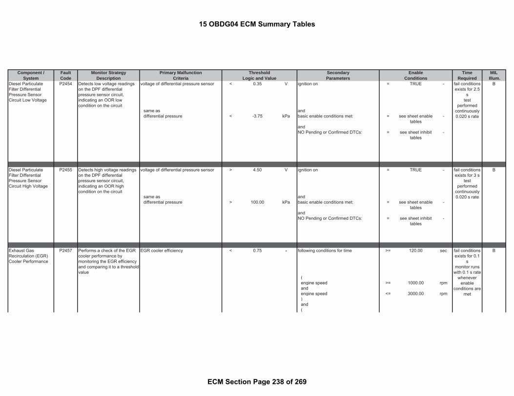
Component / Fault Monitor Strategy Primary Malfunction Secondary Time MILSystem Code Description Criteria Parameters Required Illum.
Threshold EnableLogic and Value Conditions
Diesel ParticulateFilter DifferentialPressure SensorCircuit Low Voltage
P2454 Detects low voltage readingson the DPF differentialpressure sensor circuit,indicating an OOR lowcondition on the circuit
voltage of differential pressure sensor < 0.35 V ignition on = TRUE - B
same as anddifferential pressure < -3.75 kPa basic enable conditions met: = see sheet enable
tables-
andNO Pending or Confirmed DTCs: = see sheet inhibit
tables-
Diesel ParticulateFilter DifferentialPressure SensorCircuit High Voltage
P2455 Detects high voltage readingson the DPF differentialpressure sensor circuit,indicating an OOR highcondition on the circuit
voltage of differential pressure sensor > 4.50 V ignition on = TRUE - B
same as anddifferential pressure > 100.00 kPa basic enable conditions met: = see sheet enable
tables-
andNO Pending or Confirmed DTCs: = see sheet inhibit
tables-
Exhaust GasRecirculation (EGR)Cooler Performance
P2457 Performs a check of the EGRcooler performance bymonitoring the EGR efficiencyand comparing it to a thresholdvalue
EGR cooler efficiency < 0.75 - following conditions for time >= 120.00 sec B
(engine speed >= 1000.00 rpmandengine speed <= 3000.00 rpm)and(
fail conditionsexists for 0.1
smonitor runs
with 0.1 s ratewhenever
enableconditions are
met
fail conditionsexists for 2.5
stest
performedcontinuously0.020 s rate
fail conditionsexists for 3 s
testperformed
continuously0.020 s rate
15 OBDG04 ECM Summary Tables
ECM Section Page 238 of 269

Component / Fault Monitor Strategy Primary Malfunction Secondary Time MILSystem Code Description Criteria Parameters Required Illum.
Threshold EnableLogic and Value Conditions
injection quantity >= 9.88 mm^3/rev
andinjection quantity <= 120.00 mm^3/r
ev)and(recirculated exhaust-gas mass flowdownstream of the EGR cooler
>= 6.94 g/sec
andrecirculated exhaust-gas mass flowdownstream of the EGR cooler
<= 27.78 g/sec
)andEGR controller is active = TRUE -and((a) - (b) >= 60.00 K
with(a) filtered temperature upstream ofEGR-coolerand with(b) engine temperature
)and((a) - (b) <= 3276.70 °C
with(a) filtered temperature upstream ofEGR-cooler
= measuredparameter
-
and with(b) engine temperature = measured
parameter-
)andengine coolant temperature >= 69.96 °Candengine coolant temperature <= 125.96 °Cand(actual valve position of exhaust-gasrecirculation
>= 5 %
15 OBDG04 ECM Summary Tables
ECM Section Page 239 of 269

Component / Fault Monitor Strategy Primary Malfunction Secondary Time MILSystem Code Description Criteria Parameters Required Illum.
Threshold EnableLogic and Value Conditions
andactual valve position of exhaust-gasrecirculation
<= 100.00 %
)and(control value provided for EGR coolingbypass
>= -400.00 %
andcontrol value provided for EGR coolingbypass
<= 5.00 %
fortime > 10.00 sec
)andambient pressure >= 74.80 kPaand(ambient temperature >= -7.04 °Candambient temperature <= 3003.56 °C)andDPF regeneration not active = TRUE -anddiagnostic performed in current DriveCycle
= FALSE -
andNO Pending or Confirmed DTCs: = see sheet inhibit
tables-
)andbasic enable conditions met: = see sheet enable
tables-
Diesel ParticulateFilter RegenerationFrequency
P2459 Detects a DPF that isregeneration too frequently bycomparing a threshold to asoot model.
soot mass in the particulate filter(measured used for determining DPFregeneration trigger)
> ((a) - (b)) + ((c) *(d))
g particulate filter regeneration - transitionfalse to true
= TRUE - B
with and
fail conditionsexists for
more than 1event
monitor runs
15 OBDG04 ECM Summary Tables
ECM Section Page 240 of 269

Component / Fault Monitor Strategy Primary Malfunction Secondary Time MILSystem Code Description Criteria Parameters Required Illum.
Threshold EnableLogic and Value Conditions
(a) engine out soot mass flow in theexhaust-gas (function of vehicle speedonly)
= measuredparameter
- last particulate filter regenerationsuccessful
= TRUE -
and with or(b) soot mass at the end of previousDPF regeneration
= calculatedparameter
- particulate filter regeneration must havebeen completed
= TRUE -
and with and(c) factor for calculation of a soot massvalue offset depending on thesimulated maximal base soot mass(see Look-Up-Table #61)
= 0 to 1040 g basic enable conditions met: = see sheet enabletables
-
and with and(d) factor for determination of correctionfactor for ash in the particulate filter
= 1 factor NO Pending or Confirmed DTCs: = see sheet inhibittables
-
EGR Cooler BypassControl Circuit/OpenBank 1
P245A Monitoring the EGR coolerbypass control circuit for opencircuit failures andovertemperature circuit failures
Voltage low during driver off state(indicates open circuit)
= Open Circuit: ≥200 K Ωimpedancebetween ECU pinand load signaland controllerground
- ignition on = TRUE - B
andbasic enable conditions met: = see sheet enable
tables-
andNO Pending or Confirmed DTCs: = see sheet inhibit
tables-
0.1 s ratewhenever
enableconditions are
met
fail conditionsexists for 3 smonitor runswith 0.02 s
rate wheneverenable
conditions aremet
15 OBDG04 ECM Summary Tables
ECM Section Page 241 of 269
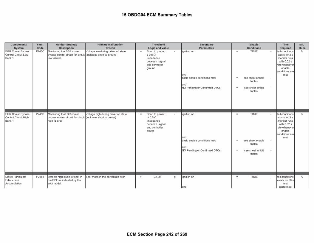
Component / Fault Monitor Strategy Primary Malfunction Secondary Time MILSystem Code Description Criteria Parameters Required Illum.
Threshold EnableLogic and Value Conditions
EGR Cooler BypassControl Circuit LowBank 1
P245C Monitoring the EGR coolerbypass control circuit for circuitlow failures
Voltage low during driver off state(indicates short-to-ground)
= Short to ground:≤ 0.5 Ωimpedancebetween signaland controllerground
- ignition on = TRUE - B
andbasic enable conditions met: = see sheet enable
tables-
andNO Pending or Confirmed DTCs: = see sheet inhibit
tables-
EGR Cooler BypassControl Circuit HighBank 1
P245D Monitoring theEGR coolerbypass control circuit for circuithigh failures
Voltage high during driver on state(indicates short to power)
= Short to power: ≤ 0.5 Ωimpedancebetween signaland controllerpower
- ignition on = TRUE - B
andbasic enable conditions met: = see sheet enable
tables-
andNO Pending or Confirmed DTCs: = see sheet inhibit
tables-
Diesel ParticulateFilter - SootAccumulation
P2463 Detects high levels of soot inthe DPF as indicated by thesoot model
Soot mass in the particulate filter > 32.00 g ignition on = TRUE - A
and
fail conditionsexists for 3 smonitor runswith 0.02 s
rate wheneverenable
conditions aremet
fail conditionsexists for 3 smonitor runswith 0.02 s
rate wheneverenable
conditions aremet
fail conditionsexists for 30 s
testperformed
15 OBDG04 ECM Summary Tables
ECM Section Page 242 of 269
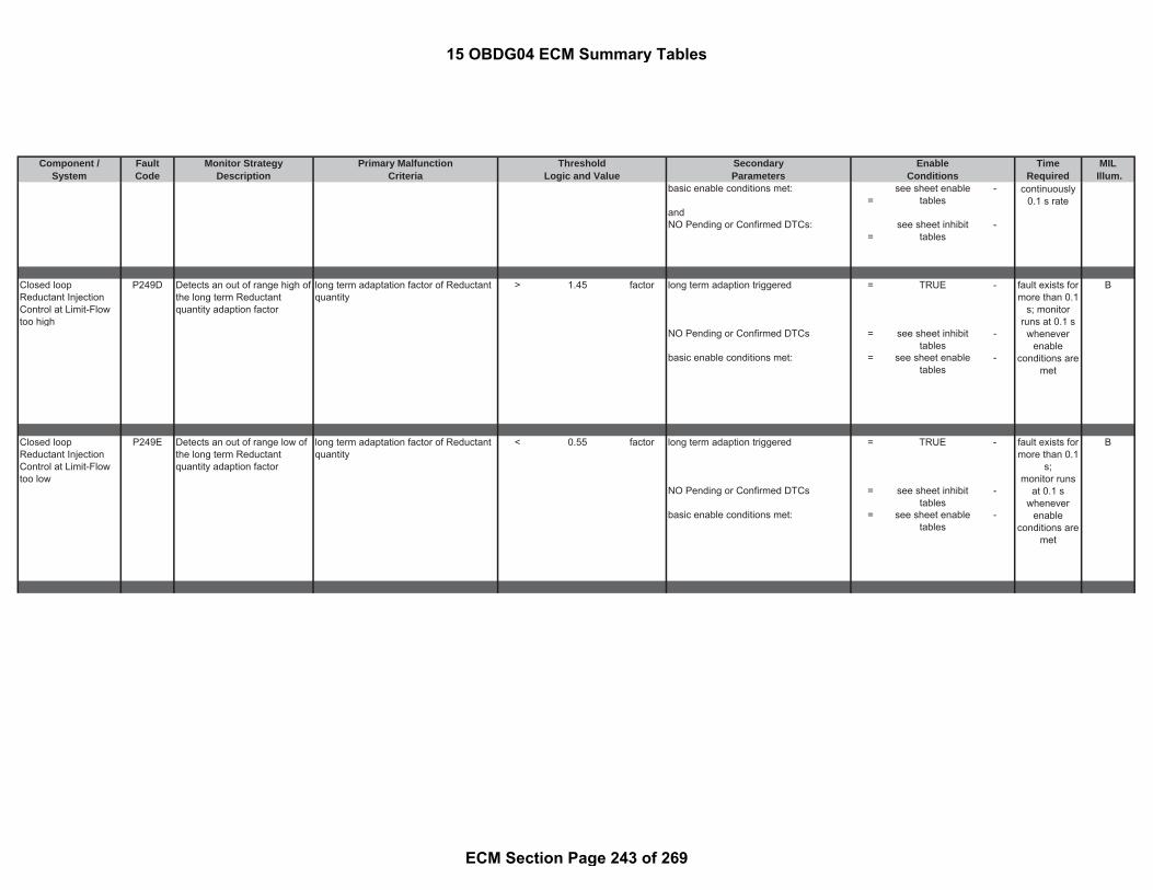
Component / Fault Monitor Strategy Primary Malfunction Secondary Time MILSystem Code Description Criteria Parameters Required Illum.
Threshold EnableLogic and Value Conditions
basic enable conditions met:=
see sheet enabletables
-
andNO Pending or Confirmed DTCs:
=see sheet inhibit
tables-
Closed loopReductant InjectionControl at Limit-Flowtoo high
P249D Detects an out of range high ofthe long term Reductantquantity adaption factor
long term adaptation factor of Reductantquantity
> 1.45 factor long term adaption triggered = TRUE - B
NO Pending or Confirmed DTCs = see sheet inhibittables
-
basic enable conditions met: = see sheet enabletables
-
Closed loopReductant InjectionControl at Limit-Flowtoo low
P249E Detects an out of range low ofthe long term Reductantquantity adaption factor
long term adaptation factor of Reductantquantity
< 0.55 factor long term adaption triggered = TRUE - B
NO Pending or Confirmed DTCs = see sheet inhibittables
-
basic enable conditions met: = see sheet enabletables
-
continuously0.1 s rate
fault exists formore than 0.1
s; monitorruns at 0.1 s
wheneverenable
conditions aremet
fault exists formore than 0.1
s;monitor runs
at 0.1 swhenever
enableconditions are
met
15 OBDG04 ECM Summary Tables
ECM Section Page 243 of 269
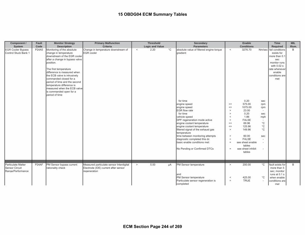
Component / Fault Monitor Strategy Primary Malfunction Secondary Time MILSystem Code Description Criteria Parameters Required Illum.
Threshold EnableLogic and Value Conditions
EGR Cooler BypassControl Stuck Bank 1
P24A5 Monitoring of the absolutechange in temperaturedownstream of the EGR coolerafter a change in bypass valveposition.
The first temperaturedifference is measured whenthe ECB valve is intrusivelycommanded closed for aperiod of time and the secondtemperature difference ismeasured when the ECB valveis commanded open for aperiod of time
Change in temperature downstream ofEGR cooler
< 2.20 °C absolute value of filtered engine torquegradient
< 3276.70 Nm/sec B
for time 0.20 secengine speed >= 575.00 rpmengine speed <= 1075.00 rpmEGR flow rate > 23.00 -
for time > 0.20 secvehicle speed < 1.86 mphDPF regeneration mode active = FALSE -engine coolant temperature >= 69.96 °Cengine coolant temperature <= 125.96 °Cfiltered signal of the exhaust gastemperature
> 149.96 °C
time between monitoring attempts > 60.00 secdiagnostic completed this dc = FALSE -basic enable conditions met: = see sheet enable
tables-
No Pending or Confirmed DTCs = see sheet inhibittables
-
Particulate MatterSensor CircuitRange/Performance
P24AF PM Sensor bypass currentrationality check
Measured particulate sensor InterdigitalElectrode (IDE) current after sensorregeneration
> 5.00 μA PM Sensor temperature > 200.00 °C B
andPM Sensor temperature < 425.00 °CParticulate sensor regeneration iscompleted
= TRUE -
fail conditionsexists for
more than 0.1sec
monitor runswith 0.02 s
rate wheneverenable
conditions aremet
fault exists formore than 5sec; monitorruns at 0.1 swhen enable
conditions aremet
15 OBDG04 ECM Summary Tables
ECM Section Page 244 of 269

Component / Fault Monitor Strategy Primary Malfunction Secondary Time MILSystem Code Description Criteria Parameters Required Illum.
Threshold EnableLogic and Value Conditions
Battery voltage (ECM) >= 11.00 VIDE supply voltage >= 41.55 VandIDE supply voltage <= 49,72 VIgnition on = TRUE -
for time > 3.00 sec
Particulate MatterSensor Heater ControlCircuitRange/Performance
P24B4 The PM sensor protection tubemonitor uses the cooling effectof exhaust gas flow insideprotection tube duringprotection heating, to ensurethe exhaust gas is reachingthe sensor. If the change inheater voltage is less than athreshold a fault is set
(detected failures: protectiontube plugged or manipulated,or sensor removed fromexhaust stream)
accumulated change in heater voltage < 100.00 % Accumulated change in exhaust gasvelocity
> 30.00 m/sec B
with (accumulated change in heater voltage = ((a) / (b)) * (100) - Absolute, filtered and temperature
compensated exhaust gas acceleration> 0.65 m/sec^
2
where and (a) change in the heater voltage = measured
parameter- Absolute, filtered and temperature
compensated exhaust gas acceleration< 6.51 m/sec^
2
and with )(b) minimum change in the heatervoltage
= 1.10 V for time > 0.90 sec
Diagnosis by the local unit is released = TRUE -means
(PM sensor temperature > 190.00 °CandPM sensor temperature < 210.00 °C)
fault exists formore than 0.1sec; monitorruns at 0.1 sonce per trip
15 OBDG04 ECM Summary Tables
ECM Section Page 245 of 269

Component / Fault Monitor Strategy Primary Malfunction Secondary Time MILSystem Code Description Criteria Parameters Required Illum.
Threshold EnableLogic and Value Conditions
Time has elapsed since diagnosis bythe local unit is released
>= 15.00 sec
Protection heating is active = TRUE -meansPM sensor heater target temperature = 200 degCPM sensor dewpoint achieved (pleasesee the definition)
= FALSE -
Initialization values have beentransferred (i.e. CAN communication withECM established)
= TRUE -
Sensor temperature at engine start > -10.04 °CandSensor temperature at engine start < 249.96 °CExhaust gas temperature > -10.04 °CandExhaust gas temperature < 179.96 °CPM sensor temperature start temperature > -10.04 °C
andPM sensor temperature start temperature < 99.96 °C
Battery voltage (ECM) >= 11.00 V
Particulate MatterSensor HeaterResistance
P24B7 Rationality check of heaterresistance (heater aged),executed once after Power-upof the powertrain main relay
A functional error of the heater selfdiagnosis of the particulate sensor isdetected in the sensor control unit
= TRUE - Functional heater self diagnosis is tested = TRUE - B
means meansElectric heater resistance based ontemperature as measured bytemperature meander (see Look-Up-Table #33)
> 2.93 to 4.13 Ohm (
or Battery voltage (ECM) >= 11.00 VElectric heater resistance based ontemperature as measured bytemperature meander (see Look-Up-Table #34)
< 1.09 to 1.81 Ohm PM sensor temperature >= -30.00 °C
andPM sensor temperature <= 150.00 °C(a) - (b) < 150.00 °C
fault exists formore than 0.1sec; monitorruns at 0.1 swhen enable
conditions aremet
15 OBDG04 ECM Summary Tables
ECM Section Page 246 of 269

Component / Fault Monitor Strategy Primary Malfunction Secondary Time MILSystem Code Description Criteria Parameters Required Illum.
Threshold EnableLogic and Value Conditions
with(a) maximum PM sensor temperature = calculated
parameter-
and with(b) minimum PM sensor temperature = calculated
parameter-
)
Debouncing time for the functional heaterself diagnosis
> 0.00 sec
ECM/PCM PowerInput Signal
P2505 Detects an interrupted supplyvoltage of the engine off timecircuit (permanent batteryvoltage supply line to ECM)
permanent supply voltage is interruptedvia open circuit
= TRUE - ignition on = TRUE - B
andbasic enable conditions met: = see sheet enable
tables-
ECM Power RelayCircuit Performance
P2510 Detects stuck power relay thatis not responding to ECMcommands to power down or arelay that is opening too earlyin power down. Stuck on isdetermined by timer valueslonger than possible if relayopened at end of after run.
counter value out of EEPROM for openthe main relay
> 2.00 counts ignition on = TRUE - B
andengine pre drive = TRUE -
fail conditionsexists for
more than 1event
monitor runsonce per
driving cyclewith 0.01 s
rate wheneverenable
conditions aremet
fail conditionsexists for 0.02
smonitor runs
once perdriving cycle
duringpredrive with0.02 s ratewhenever
enable
15 OBDG04 ECM Summary Tables
ECM Section Page 247 of 269
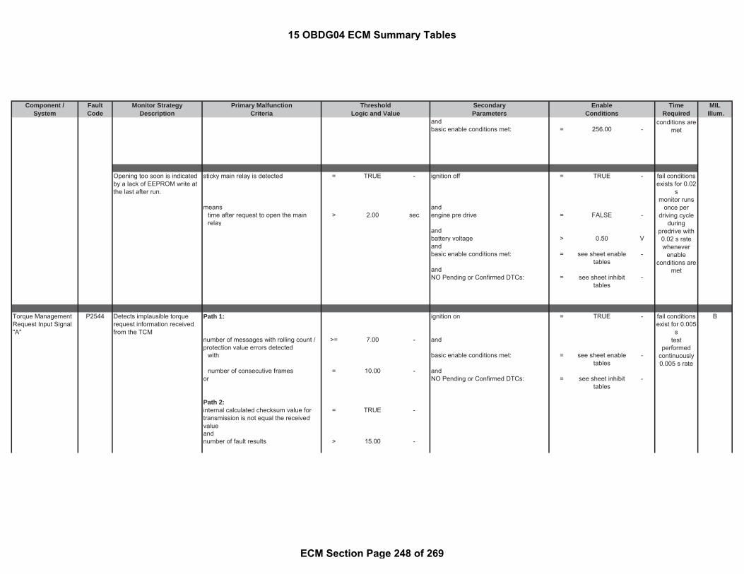
Component / Fault Monitor Strategy Primary Malfunction Secondary Time MILSystem Code Description Criteria Parameters Required Illum.
Threshold EnableLogic and Value Conditions
andbasic enable conditions met: = 256.00 -
Opening too soon is indicatedby a lack of EEPROM write atthe last after run.
sticky main relay is detected = TRUE - ignition off = TRUE -
means andtime after request to open the mainrelay
> 2.00 sec engine pre drive = FALSE -
andbattery voltage > 0.50 Vandbasic enable conditions met: = see sheet enable
tables-
andNO Pending or Confirmed DTCs: = see sheet inhibit
tables-
Torque ManagementRequest Input Signal"A"
P2544 Detects implausible torquerequest information receivedfrom the TCM
Path 1: ignition on = TRUE - B
number of messages with rolling count /protection value errors detected
>= 7.00 - and
with basic enable conditions met: = see sheet enabletables
-
number of consecutive frames = 10.00 - andor NO Pending or Confirmed DTCs: = see sheet inhibit
tables-
Path 2:internal calculated checksum value fortransmission is not equal the receivedvalue
= TRUE -
andnumber of fault results > 15.00 -
fail conditionsexist for 0.005
stest
performedcontinuously0.005 s rate
conditions aremet
fail conditionsexists for 0.02
smonitor runs
once perdriving cycle
duringpredrive with0.02 s ratewhenever
enableconditions are
met
15 OBDG04 ECM Summary Tables
ECM Section Page 248 of 269
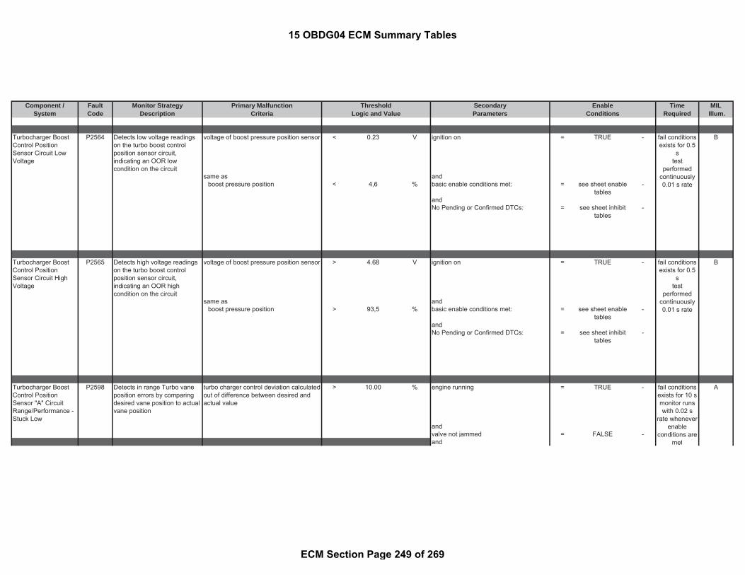
Component / Fault Monitor Strategy Primary Malfunction Secondary Time MILSystem Code Description Criteria Parameters Required Illum.
Threshold EnableLogic and Value Conditions
Turbocharger BoostControl PositionSensor Circuit LowVoltage
P2564 Detects low voltage readingson the turbo boost controlposition sensor circuit,indicating an OOR lowcondition on the circuit
voltage of boost pressure position sensor < 0.23 V ignition on = TRUE - B
same as andboost pressure position < 4,6 % basic enable conditions met: = see sheet enable
tables-
andNo Pending or Confirmed DTCs: = see sheet inhibit
tables-
Turbocharger BoostControl PositionSensor Circuit HighVoltage
P2565 Detects high voltage readingson the turbo boost controlposition sensor circuit,indicating an OOR highcondition on the circuit
voltage of boost pressure position sensor > 4.68 V ignition on = TRUE - B
same as andboost pressure position > 93,5 % basic enable conditions met: = see sheet enable
tables-
andNo Pending or Confirmed DTCs: = see sheet inhibit
tables-
Turbocharger BoostControl PositionSensor "A" CircuitRange/Performance -Stuck Low
P2598 Detects in range Turbo vaneposition errors by comparingdesired vane position to actualvane position
turbo charger control deviation calculatedout of difference between desired andactual value
> 10.00 % engine running = TRUE - A
andvalve not jammed = FALSE -and
fail conditionsexists for 0.5
stest
performedcontinuously0.01 s rate
fail conditionsexists for 0.5
stest
performedcontinuously0.01 s rate
fail conditionsexists for 10 smonitor runswith 0.02 s
rate wheneverenable
conditions aremet
15 OBDG04 ECM Summary Tables
ECM Section Page 249 of 269
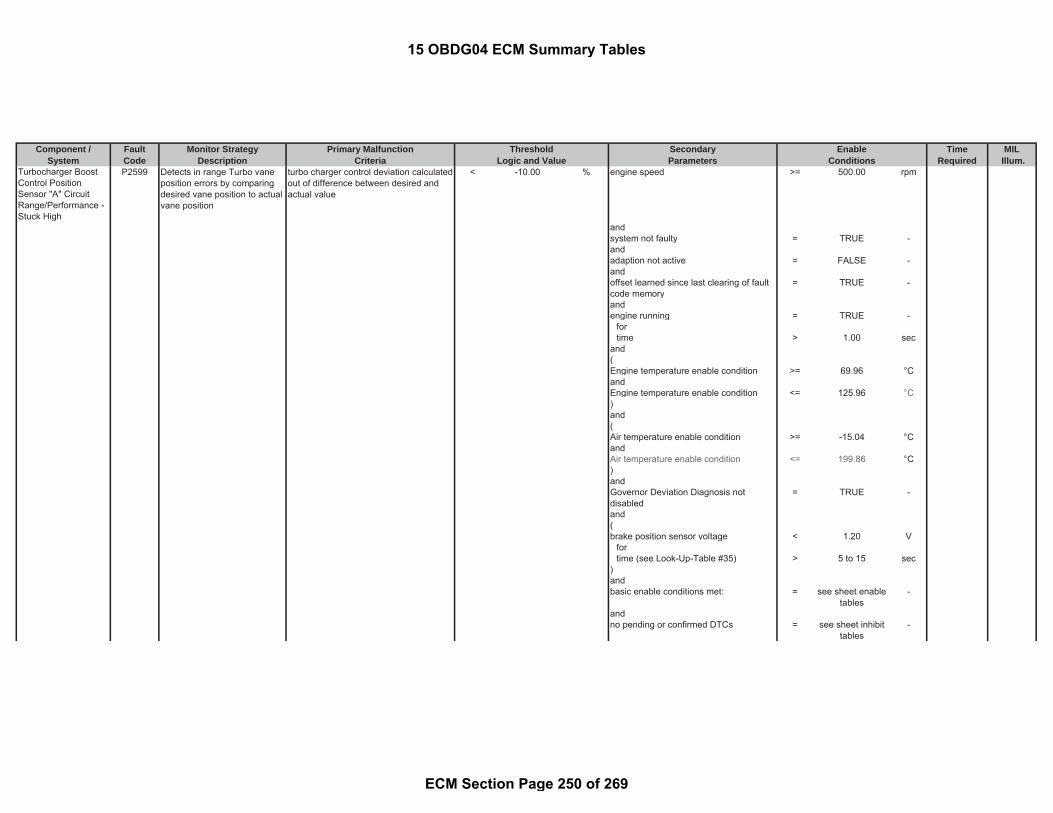
Component / Fault Monitor Strategy Primary Malfunction Secondary Time MILSystem Code Description Criteria Parameters Required Illum.
Threshold EnableLogic and Value Conditions
Turbocharger BoostControl PositionSensor "A" CircuitRange/Performance -Stuck High
P2599 Detects in range Turbo vaneposition errors by comparingdesired vane position to actualvane position
turbo charger control deviation calculatedout of difference between desired andactual value
< -10.00 % engine speed >= 500.00 rpm
andsystem not faulty = TRUE -andadaption not active = FALSE -andoffset learned since last clearing of faultcode memory
= TRUE -
andengine running = TRUE -
fortime > 1.00 sec
and(Engine temperature enable condition >= 69.96 °CandEngine temperature enable condition <= 125.96 °C)and(Air temperature enable condition >= -15.04 °CandAir temperature enable condition <= 199.86 °C)andGovernor Deviation Diagnosis notdisabled
= TRUE -
and(brake position sensor voltage < 1.20 V
fortime (see Look-Up-Table #35) > 5 to 15 sec
)andbasic enable conditions met: = see sheet enable
tables-
andno pending or confirmed DTCs = see sheet inhibit
tables-
15 OBDG04 ECM Summary Tables
ECM Section Page 250 of 269

Component / Fault Monitor Strategy Primary Malfunction Secondary Time MILSystem Code Description Criteria Parameters Required Illum.
Threshold EnableLogic and Value Conditions
Unmetered Fuel -Forced EngineShutdown
P25BD Detects engine overspeed inthe event that there is an errorin the ECM or engine damagehas occurred which is resultingin the engine speed increasingbeyond desired control limits.Upon failure detection, theengine will be shutdown byclosing the diesel intake airvalve and disabling the fuelinjectors
current engine speed > 5400.00 rpm ignition on = TRUE - A
andbasic enable conditions met: = see sheet enable
tables-
andNO Pending or Confirmed DTCs: = see sheet inhibit
tables-
Control Module PowerOff TimerPerformance
P262B Detects a failure in the engineoff timer if during the after runthe internal SW timer and theEOT do not correlate. Afailure is detected when therespective timers are startedafter a calibration time thenboth are stopped, if thedifference between thecalculated times exceeds acalibrated threshold a fault isset.
Path 1: time since engine post drive/ afterun < 20.00 sec B
acquired engine off time < (a) * (b) - andor engine post drive/ afterun = TRUE -Path 2: andacquired engine off time > (c) * (b) - basic enable conditions met: = see sheet enable
tables-
(
fail conditionsexists for .01
s testperformed
continuously
fail conditionsexists for 0.01
smonitor runs
once perdriving cyclewith 0.01 s
rate wheneverenable
conditions aremet
15 OBDG04 ECM Summary Tables
ECM Section Page 251 of 269

Component / Fault Monitor Strategy Primary Malfunction Secondary Time MILSystem Code Description Criteria Parameters Required Illum.
Threshold EnableLogic and Value Conditions
where(a) lower tolerance factor = 0.94 factorand(b) evaluation time period = 20.00 secand(b) upper tolerance factor = 1.06 factor
)
MIL Control CircuitLow
P263A Diagnoses the MalfunctionIndicator Lamp (MIL) low sidedriver circuit for circuit faults.
Voltage low during driver off state(indicates short-to-ground)
= Short to ground:≤ 0.5 Ωimpedancebetween signaland controllerground
- circuit active at low current = TRUE - A (no MIL)
andignition on = TRUE -andECU Initialization tasks in progress = FALSE -
fortime > 0.10 sec
andECU Shutdown tasks in progress = FALSE -
fortime > 1.00 sec
andBattery voltage > 10.50 V
fortime > 3.00 sec
andbasic enable conditions met: see sheet enable
tables-
MIL Control CircuitHigh
P263B Diagnoses the MalfunctionIndicator Lamp (MIL) low sidedriver circuit for circuit faults.
Voltage high during driver on state(indicates short to power)
= Short to power: ≤ 0.5 Ωimpedancebetween signaland controllerpower
- lamp is commanded off A (no MIL)
and
fail conditionsexists for 3 smonitor runswith 0.01 s
rate wheneverenable
conditions aremet
fail conditionsexists for 2 smonitor runswith 0.01 s
rate wheneverenable
conditions aremet
15 OBDG04 ECM Summary Tables
ECM Section Page 252 of 269

Component / Fault Monitor Strategy Primary Malfunction Secondary Time MILSystem Code Description Criteria Parameters Required Illum.
Threshold EnableLogic and Value Conditions
ignition on = TRUEandECU Initialization tasks in progress = FALSE
fortime > 0.10 sec
andECU Shutdown tasks in progress = FALSE
fortime > 1.00 sec
andBattery voltage > 10.50 V
fortime > 3.00 sec
andbasic enable conditions met: = see sheet enable
tables-
Fuel Supply HeaterControl Circuit/Open
P2687 Diagnoses the Fuel FilterHeater low side driver circuitfor open circuit faults.
Voltage low during driver off state(indicates open circuit)
= Open Circuit:200 K impedancebetween ECU pinand load
- engine post drive/ afterun = FALSE B
fortime > 1.00 sec
andbattery voltage > 11.00 V
fortime > 3.00 sec
andengine speed (see Look-Up-Table #81) > 850 to 1100 rpm
fortime > 0.10 sec
andbasic enable conditions met: = see sheet enable
tables-
fail conditionsexists for 2 smonitor runs
with 0.2 s ratewhenever
enableconditions are
met
15 OBDG04 ECM Summary Tables
ECM Section Page 253 of 269

Component / Fault Monitor Strategy Primary Malfunction Secondary Time MILSystem Code Description Criteria Parameters Required Illum.
Threshold EnableLogic and Value Conditions
Fuel Supply HeaterControl Circuit Low
P2688 Diagnoses the Fuel FilterHeater low side driver circuitfor short circuit to groundfaults.
Voltage low during driver off state(indicates short-to-ground)
= Short to ground: 0.5
impedancebetween signaland controllerground
- engine post drive/ afterun = FALSE - B
fortime > 1.00 sec
andbattery voltage > 11.00 V
fortime > 3.00 sec
andengine speed (see Look-Up-Table #81) > 850 to 1100 rpm
fortime > 0.10 sec
andbasic enable conditions met: = see sheet enable
tables-
Fuel Supply HeaterControl Circuit High
P2689 Diagnoses the Fuel FilterHeater low side driver circuitfor short circuit to batteryfaults.
Voltage high during driver on state(indicates short to power)
= Short to power: ≤ 0.5 Ωimpedancebetween signaland controllerpower
- engine post drive/ afterun = FALSE - B
fortime > 1.00 sec
andbattery voltage > 11.00 V
fortime > 3.00 sec
andengine speed (see Look-Up-Table #81) > 850 to 1100 rpm
fortime > 0.10 sec
and
fail conditionsexists for 2 smonitor runs
with 0.2 s ratewhenever
enableconditions are
met
fail conditionsexists for 2 smonitor runs
with 0.2 s ratewhenever
enableconditions are
met
15 OBDG04 ECM Summary Tables
ECM Section Page 254 of 269

Component / Fault Monitor Strategy Primary Malfunction Secondary Time MILSystem Code Description Criteria Parameters Required Illum.
Threshold EnableLogic and Value Conditions
basic enable conditions met: = see sheet enabletables
-
Cylinder 1 InjectorData Incompatible
P268C Detects a unprogrammedInjector Calibration Data (IQA)in ECM
Path 1: engine pre drive = TRUE - B
the checksum of the injector adjustmentcode value is plausible
= FALSE - and
basic enable conditions met: = see sheet enabletables
-
Cylinder 3 InjectorData Incompatible
P268E Detects a unprogrammedInjector Calibration Data (IQA)in ECM
Path 1: engine pre drive = TRUE - B
the checksum of the injector adjustmentcode value is plausible
= FALSE - and
basic enable conditions met: = see sheet enabletables
-
Cylinder 4 InjectorData Incompatible
P268F Detects a unprogrammedInjector Calibration Data (IQA)in ECM
Path 1: engine pre drive = TRUE - B
the checksum of the injector adjustmentcode value is plausible
= FALSE - and
fail conditionsexist for 1 smonitor runs
once perdriving cycle
duringpredrive with
1 s rate
fail conditionsexist for 1 smonitor runs
once perdriving cycle
duringpredrive with
1 s rate
fail conditionsexist for 1 smonitor runs
once perdriving cycle
15 OBDG04 ECM Summary Tables
ECM Section Page 255 of 269

Component / Fault Monitor Strategy Primary Malfunction Secondary Time MILSystem Code Description Criteria Parameters Required Illum.
Threshold EnableLogic and Value Conditions
basic enable conditions met: = see sheet enabletables
-
Cylinder 2 InjectorData Incompatible
P268D Detects a unprogrammedInjector Calibration Data (IQA)in ECM
Path 1: engine pre drive = TRUE - B
the checksum of the injector adjustmentcode value is plausible
= FALSE - and
basic enable conditions met: = see sheet enabletables
-
O2 Sensor CircuitRange/PerformanceBank 1 Sensor 1
P2A00 Monitoring the measured A/Fsensor voltage for higher thanexpected values, indicating anOOR high failure
filtered A/F sensor voltage >= 4.70 V modeled exhaust-gas pressure < 250.00 kPa B
The calibration scheduler has requesteda calibration sequence during signalacquisition
=TRUE -
A/F sensor temperature (based onsensor internal resistance) >= 804.96 °C
andStatus bit for valid A/F sensor innerResistance (see parameter definitiontable)
=TRUE -
and
duringpredrive with
1 s rate
fail conditionsexist for 1 smonitor runs
once perdriving cycle
duringpredrive with
1 s rate
fault exists formore than 2sec; monitorruns at 0.1 swhen enable
conditions aremet
15 OBDG04 ECM Summary Tables
ECM Section Page 256 of 269

Component / Fault Monitor Strategy Primary Malfunction Secondary Time MILSystem Code Description Criteria Parameters Required Illum.
Threshold EnableLogic and Value Conditions
A/F sensor error status bit (seeparameter definition table) = FALSE -
andTemperature of lambda sensor < 823.96 °Cand °CTemperature of lambda sensor > 805.96 °C
basic enable conditions met: = see sheet enabletables
-
NO Pending or Confirmed DTCs: = see sheet inhibittables
-
Reductant DeliveryPerformance monitor
P2BAA Compared EWMA filteredpressure drop with thethreshold
EWMA filtered pressure drop < 365.00 kPa A
Modeled SCR catalyst temperature >= 199.96 °CModeled SCR catalyst temperature <= 399.96 °CTemperature gradient of SCR >= -40.00 °C/secTemperature gradient of SCR <= 40.00 °C/sec
for time > 0.20 secExhaust mass flow > 0.56 g/secExhaust mass flow <= 13.89 g/sec( a) - ( b ) > -0.30 g
( a ) Desired NH3 load level = calculatedparameter
-
( b ) estimated NH3 load level = calculatedparameter
-
Estimated NH3 load level < 3.00 gStatus of the SCR adaptation plausibilitycheck active (please see the definition)
= FALSE -
DPF Regen not active = TRUE -Reductant dosing off request = FALSE -SCR control sub state (please see thedefinition)
= COSCR_METERINGCONTROL
Dosed reductant amount of currentdriving cycle
>= 7.00 g
Dosed reductant amount of currentdriving cycle
<= 100.00 g
Dwell time in Metering control substate <= 42949672.95 secamplitude of SCR pressure signal >= 0.00 kPaamplitude of SCR pressure signal <= 100.00 kPa
fault exists formore than 1
event; monitorruns at 0.1 s
15 OBDG04 ECM Summary Tables
ECM Section Page 257 of 269

Component / Fault Monitor Strategy Primary Malfunction Secondary Time MILSystem Code Description Criteria Parameters Required Illum.
Threshold EnableLogic and Value Conditions
State of Reductant injection valveComponent Protection (please seedefinition)
= FALSE -
vehicle speed < 4.38 mphfor time > 4.00 sec
NO Pending or Confirmed DTCs = see sheetinhibit tables
-
basic enable conditions met: = see sheet enabletables
-
EWMA fast initialization mode:EWMA filter coefficient for FastInitialization mode
= 0.28 factor
Maximum number of pressure drop perdriving cycle in Fast Initialization mode
>= 3.00 counts
Total number of pressure drop for FastInitialization mode
= 4.00 counts
EWMA Rapid Response mode:Pressure difference: (a) - (b) > -12.00 kPa(a) measured pressure drop = measured
parameter-
(b) EWMA filtered pressure drop = calculatedparameter
-
EWMA filter coefficient for Responseto Step Change mode
= 0.20 factor
Maximum number of pressure drop perdriving cycle in Response to StepChange mode
>= 3.00 count
Total number of pressure dropmeasurement for Response to StepChange mode
8.00 count
EWMA stabilized mode:EWMA filter coefficient for stabilizedmode
= 0.20 factor
Total number of pressure drop forstabilized mode
= 1.00 counts
15 OBDG04 ECM Summary Tables
ECM Section Page 258 of 269
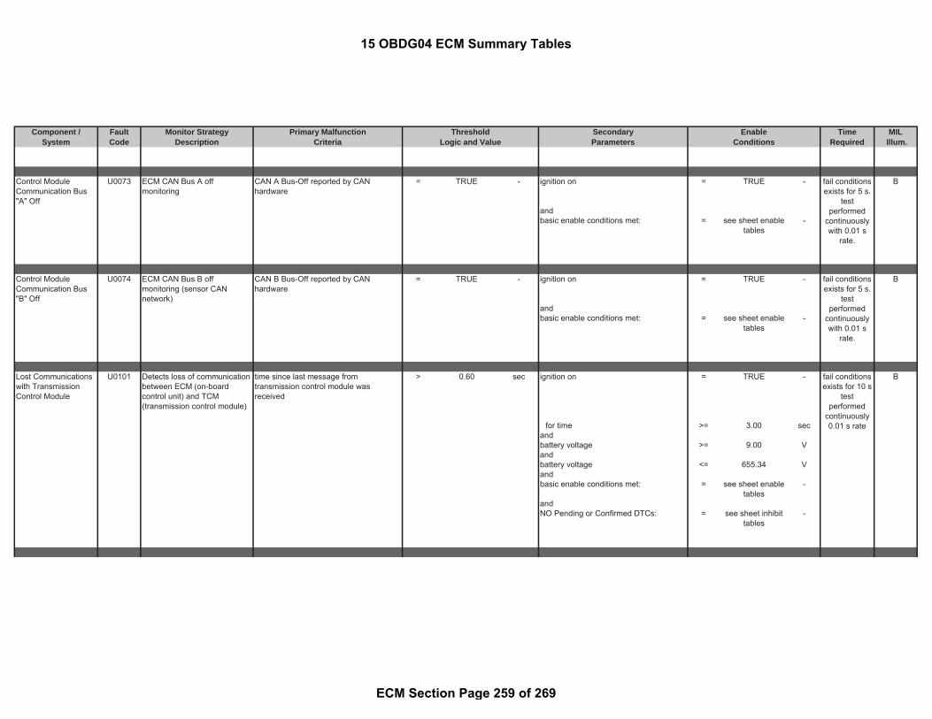
Component / Fault Monitor Strategy Primary Malfunction Secondary Time MILSystem Code Description Criteria Parameters Required Illum.
Threshold EnableLogic and Value Conditions
Control ModuleCommunication Bus"A" Off
U0073 ECM CAN Bus A offmonitoring
CAN A Bus-Off reported by CANhardware
= TRUE - ignition on = TRUE - B
andbasic enable conditions met: = see sheet enable
tables-
Control ModuleCommunication Bus"B" Off
U0074 ECM CAN Bus B offmonitoring (sensor CANnetwork)
CAN B Bus-Off reported by CANhardware
= TRUE - ignition on = TRUE - B
andbasic enable conditions met: = see sheet enable
tables-
Lost Communicationswith TransmissionControl Module
U0101 Detects loss of communicationbetween ECM (on-boardcontrol unit) and TCM(transmission control module)
time since last message fromtransmission control module wasreceived
> 0.60 sec ignition on = TRUE - B
for time >= 3.00 secandbattery voltage >= 9.00 Vandbattery voltage <= 655.34 Vandbasic enable conditions met: = see sheet enable
tables-
andNO Pending or Confirmed DTCs: = see sheet inhibit
tables-
fail conditionsexists for 5 s.
testperformed
continuouslywith 0.01 s
rate.
fail conditionsexists for 5 s.
testperformed
continuouslywith 0.01 s
rate.
fail conditionsexists for 10 s
testperformed
continuously0.01 s rate
15 OBDG04 ECM Summary Tables
ECM Section Page 259 of 269

Component / Fault Monitor Strategy Primary Malfunction Secondary Time MILSystem Code Description Criteria Parameters Required Illum.
Threshold EnableLogic and Value Conditions
Lost Communicationswith Glow PlugControl Module
U0106 Detects loss of communicationbetween ECM (on-boardcontrol unit) and GPCM (GlowPlug Control Module)
time since last message from glow plugcontrol module was received
> 0.25 sec ignition on = TRUE - B
for time >= 3.00 secandbattery voltage >= 9.00 Vandbattery voltage <= 655.34 Vandbasic enable conditions met: = see sheet enable
tables-
andNO Pending or Confirmed DTCs: = see sheet inhibit
tables-
Lost CommunicationWith Chassis ControlModule "A"
U012A Detects loss of communicationbetween ECM (on-boardcontrol unit) and Fuel PumpControl Module
time since last message from fuel pumpcontrol module was received
> 0.50 sec ignition on = TRUE - B
for time >= 3.00 secandbattery voltage >= 9.00 Vandbattery voltage <= 655.34 Vandbasic enable conditions met: = see sheet enable
tables-
andNO Pending or Confirmed DTCs: = see sheet inhibit
tables-
Lost Communicationwith ReductantControl Module
U010E CAN frame not received aftera calibrated number of times
Counts up when message frame is notreceived in the time out interval
> 40.00 counts CAN Bus is Active = TRUE - A
fail conditionsexists for 10 s
testperformed
continuously0.02 s rate
fail conditionsexists for 10 s
testperformed
continuously0.1 s rate
fail conditionsexists for
more than 5
15 OBDG04 ECM Summary Tables
ECM Section Page 260 of 269

Component / Fault Monitor Strategy Primary Malfunction Secondary Time MILSystem Code Description Criteria Parameters Required Illum.
Threshold EnableLogic and Value Conditions
Can Bus Initialized ( CAN Bus is Active )
consisting of:ignition = TRUE -
fortime > 5.00 sec
battery voltage < 655.34 Vbattery voltage > 9.00 V
CAN frame rolling counter andprotection value verificationusing a sliding windowevaluation
DLS1 Sliding Window error counter >= 8.00 counts CAN Bus is Active = TRUE -
Check of level sensor within a number of message frames = 9.00 counts Can Bus Initialized ( CAN Bus is Active )
consisting of:ignition = TRUE -
fortime > 5.00 sec
battery voltage < 655.34 Vbattery voltage > 9.00 V
CAN frame rolling counter andprotection value verificationusing a sliding windowevaluation
DLS2 Sliding Window error counter >= 8.00 counts CAN Bus is Active = TRUE -
Check of temperature sensor within a number of message frames = 9.00 counts Can Bus Initialized ( CAN Bus is Active )
consisting of:ignition = TRUE -
fortime > 5.00 sec
battery voltage < 655.34 Vbattery voltage > 9.00 V
monitor runswith 1 s rate
monitor runswith 1 s rate
secmonitor runs
with 0.1 s rate
15 OBDG04 ECM Summary Tables
ECM Section Page 261 of 269
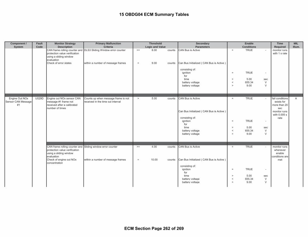
Component / Fault Monitor Strategy Primary Malfunction Secondary Time MILSystem Code Description Criteria Parameters Required Illum.
Threshold EnableLogic and Value Conditions
CAN frame rolling counter andprotection value verificationusing a sliding windowevaluation
DLS3 Sliding Window error counter >= 8.00 counts CAN Bus is Active = TRUE -
Check of error states within a number of message frames = 9.00 counts Can Bus Initialized ( CAN Bus is Active )
consisting of:ignition = TRUE -
fortime > 5.00 sec
battery voltage < 655.34 Vbattery voltage > 9.00 V
Engine Out NOxSensor CAN Message
#1
U029D Engine out NOx sensor CANmessage #1 frame notreceived after a calibratednumber of times
Counts up when message frame is notreceived in the time out interval
> 5.00 counts CAN Bus is Active = TRUE - A
Can Bus Initialized ( CAN Bus is Active )
consisting of:ignition = TRUE -
fortime > 5.00 sec
battery voltage < 655.34 Vbattery voltage > 9.00 V
CAN frame rolling counter andprotection value verificationusing a sliding windowevaluation
Sliding window error counter >= 4.00 counts CAN Bus is Active = TRUE -
Check of engine out NOxconcentration
within a number of message frames = 10.00 counts Can Bus Initialized ( CAN Bus is Active )
consisting of:ignition = TRUE -
fortime > 5.00 sec
battery voltage < 655.34 Vbattery voltage > 9.00 V
fail conditionsexists for
more than 20sec
monitor runswith 0.005 s
rate
monitor runswhenever
enableconditions are
met
monitor runswith 1 s rate
15 OBDG04 ECM Summary Tables
ECM Section Page 262 of 269

Component / Fault Monitor Strategy Primary Malfunction Secondary Time MILSystem Code Description Criteria Parameters Required Illum.
Threshold EnableLogic and Value Conditions
CAN frame rolling counter andprotection value verificationusing a sliding windowevaluation
Sliding window error counter >= 4.00 counts CAN Bus is Active = TRUE -
Check of engine out NOxsensor status
within a number of message frames = 10.00 counts Can Bus Initialized ( CAN Bus is Active )
consisting of:ignition = TRUE -
fortime > 5.00 sec
battery voltage < 655.34 Vbattery voltage > 9.00 V
Engine Out NOxSensor CAN Message
#2
Engine out NOx sensor CANmessage #2 frame notreceived after a calibratednumber of times
Counts up when message frame is notreceived in the time out interval
> 5.00 counts CAN Bus is Active = TRUE -
Can Bus Initialized ( CAN Bus is Active )
consisting of:ignition = TRUE -
fortime > 5.00 sec
battery voltage < 655.34 Vbattery voltage > 9.00 V
CAN frame rolling counter andprotection value verificationusing a sliding windowevaluation
Sliding window error counter >= 4.00 counts CAN Bus is Active = TRUE -
Check of engine out NOxsensor error status
within a number of message frames = 10.00 counts Can Bus Initialized ( CAN Bus is Active )
consisting of:ignition = TRUE -
fortime > 5.00 sec
battery voltage < 655.34 V
monitor runswhenever
enableconditions are
met
fail conditionsexists for
more than 20sec
monitor runswith 0.005 s
rate
monitor runswhenever
enableconditions are
met
15 OBDG04 ECM Summary Tables
ECM Section Page 263 of 269

Component / Fault Monitor Strategy Primary Malfunction Secondary Time MILSystem Code Description Criteria Parameters Required Illum.
Threshold EnableLogic and Value Conditions
battery voltage > 9.00 V
Engine Out NOxSensor CAN Message
#3
Engine out NOx sensor CANmessage #3 frame notreceived after a calibratednumber of times
Counts up when message frame is notreceived in the time out interval
> 5.00 counts CAN Bus is Active = TRUE -
Can Bus Initialized ( CAN Bus is Active )
consisting of:ignition = TRUE -
fortime > 5.00 sec
battery voltage < 655.34 Vbattery voltage > 9.00 V
CAN frame rolling counter andprotection value verificationusing a sliding windowevaluation
Sliding window error counter >= 8.00 counts CAN Bus is Active = TRUE -
Check of engine out NOxsensor oxygen concentration
within a number of message frames = 9.00 counts Can Bus Initialized ( CAN Bus is Active )
consisting of:ignition = TRUE -
fortime > 5.00 sec
battery voltage < 655.34 Vbattery voltage > 9.00 V
Engine Out NOxSensor CAN Message
#4
Engine out NOx sensor CANmessage #4 frame notreceived after a calibratednumber of times
Counts up when message frame is notreceived in the time out interval
> 25.00 counts CAN Bus is Active = TRUE -
Can Bus Initialized ( CAN Bus is Active )
consisting of:ignition = TRUE -
for
fail conditionsexists for
more than 20sec
monitor runswith 0.005 s
rate
monitor runswhenever
enableconditions are
met
fail conditionsexists for
more than 20sec
monitor runswith 0.02 s
rate
15 OBDG04 ECM Summary Tables
ECM Section Page 264 of 269

Component / Fault Monitor Strategy Primary Malfunction Secondary Time MILSystem Code Description Criteria Parameters Required Illum.
Threshold EnableLogic and Value Conditions
time > 5.00 secbattery voltage < 655.34 Vbattery voltage > 9.00 V
CAN frame rolling counter andprotection value verificationusing a sliding windowevaluation
Sliding window error counter >= 8.00 counts CAN Bus is Active = TRUE -
Check of engine out NOxsensor heater resistance
within a number of message frames = 9.00 counts Can Bus Initialized ( CAN Bus is Active )
consisting of:ignition = TRUE -
fortime > 5.00 sec
battery voltage < 655.34 Vbattery voltage > 9.00 V
Engine Out NOxSensor CAN Message
#5
Engine out NOx sensor CANmessage #5 frame notreceived after a calibratednumber of times
Counts up when message frame is notreceived in the time out interval
> 12.00 counts CAN Bus is Active = TRUE -
Can Bus Initialized ( CAN Bus is Active )
consisting of:ignition = TRUE -
fortime > 5.00 sec
battery voltage < 655.34 Vbattery voltage > 9.00 V
Post Catalyst NOxSensor CAN Message
#1
U029E Post catalyst NOx sensor CANmessage #1 frame notreceived after a calibratednumber of times
Counts up when message frame is notreceived in the time out interval
> 5.00 counts CAN Bus is Active = TRUE - A
Can Bus Initialized ( CAN Bus is Active )
consisting of:
fail conditionsexists for
more than 20sec
monitor runswith 0.1 s rate
fail conditionsexists for
more than 21sec
monitor runswith 0.005 s
rate
monitor runswhenever
enableconditions are
met
15 OBDG04 ECM Summary Tables
ECM Section Page 265 of 269

Component / Fault Monitor Strategy Primary Malfunction Secondary Time MILSystem Code Description Criteria Parameters Required Illum.
Threshold EnableLogic and Value Conditions
ignition = TRUE -fortime > 5.00 sec
battery voltage < 655.34 Vbattery voltage > 9.00 V
CAN frame rolling counter andprotection value verificationusing a sliding windowevaluation
Sliding window error counter >= 4.00 counts CAN Bus is Active = TRUE -
Check of post catalyst NOxconcentration
within a number of message frames = 10.00 counts Can Bus Initialized ( CAN Bus is Active )
consisting of:ignition = TRUE -
fortime > 5.00 sec
battery voltage < 655.34 Vbattery voltage > 9.00 V
CAN frame rolling counter andprotection value verificationusing a sliding windowevaluation
Sliding window error counter >= 4.00 counts CAN Bus is Active = TRUE -
Check of post catalyst NOxsensor status
within a number of message frames = 10.00 counts Can Bus Initialized ( CAN Bus is Active )
consisting of:ignition = TRUE -
fortime > 5.00 sec
battery voltage < 5.00 secbattery voltage > 655.34 V
9.00 V
Post Catalyst NOxSensor CAN Message
#2
Post catalyst NOx sensor CANmessage #2 frame notreceived after a calibratednumber of times
Counts up when message frame is notreceived in the time out interval
> 5.00 counts CAN Bus is Active = TRUE -
monitor runswhenever
enableconditions are
met
monitor runswhenever
enableconditions are
met
fail conditionsexists for
more than 21sec
15 OBDG04 ECM Summary Tables
ECM Section Page 266 of 269

Component / Fault Monitor Strategy Primary Malfunction Secondary Time MILSystem Code Description Criteria Parameters Required Illum.
Threshold EnableLogic and Value Conditions
Can Bus Initialized ( CAN Bus is Active )
consisting of:ignition = TRUE -
fortime > 5.00 sec
battery voltage < 655.34 Vbattery voltage > 9.00 V
CAN frame rolling counter andprotection value verificationusing a sliding windowevaluation
Sliding window error counter >= 4.00 counts CAN Bus is Active = TRUE -
Check of post catalyst NOxsensor error status
within a number of message frames = 10.00 counts Can Bus Initialized ( CAN Bus is Active )
consisting of:ignition = TRUE -
fortime > 5.00 sec
battery voltage < 655.34 Vbattery voltage > 9.00 V
Post Catalyst NOxSensor CAN Message
#3
Post catalyst NOx sensor CANmessage #3 frame notreceived after a calibratednumber of times
Counts up when message frame is notreceived in the time out interval
> 5.00 counts CAN Bus is Active = TRUE -
Can Bus Initialized ( CAN Bus is Active )
consisting of:ignition = TRUE -
fortime > 5.00 sec
battery voltage < 655.34 Vbattery voltage > 9.00 V
monitor runswith 0.005 s
rate
monitor runswhenever
enableconditions are
met
fail conditionsexists for
more than 21sec
monitor runswith 0.005 s
rate
15 OBDG04 ECM Summary Tables
ECM Section Page 267 of 269

Component / Fault Monitor Strategy Primary Malfunction Secondary Time MILSystem Code Description Criteria Parameters Required Illum.
Threshold EnableLogic and Value Conditions
CAN frame rolling counter andprotection value verificationusing a sliding windowevaluation
Sliding window error counter >= 8.00 counts CAN Bus is Active = TRUE -
Check of post catalyst NOxsensor oxygen concentration
within a number of message frames = 10.00 counts Can Bus Initialized ( CAN Bus is Active )
consisting of:ignition = TRUE -
fortime > 5.00 sec
battery voltage < 655.34 Vbattery voltage > 9.00 V
Post Catalyst NOxSensor CAN Message
#4
Post catalyst NOx sensor CANmessage #4 frame notreceived after a calibratednumber of times
Counts up when message frame is notreceived in the time out interval
> 25.00 counts CAN Bus is Active = TRUE -
Can Bus Initialized ( CAN Bus is Active )
consisting of:ignition = TRUE -
fortime > 5.00 sec
battery voltage < 655.34 Vbattery voltage > 9.00 V
CAN frame rolling counter andprotection value verificationusing a sliding windowevaluation
Sliding window error counter >= 8.00 counts CAN Bus is Active = TRUE -
Check of post catalyst NOxsensor heater resistance
within a number of message frames = 9.00 counts Can Bus Initialized ( CAN Bus is Active )
consisting of:ignition = TRUE -
fortime > 5.00 sec
battery voltage < 655.34 Vbattery voltage > 9.00 V
monitor runswhenever
enableconditions are
met
monitor runswhenever
enableconditions are
met
fail conditionsexists for
more than 21sec
monitor runswith 0.02 s
rate
15 OBDG04 ECM Summary Tables
ECM Section Page 268 of 269

Component / Fault Monitor Strategy Primary Malfunction Secondary Time MILSystem Code Description Criteria Parameters Required Illum.
Threshold EnableLogic and Value Conditions
Post Catalyst NOxSensor CAN Message
#5
Post catalyst NOx sensor CANmessage #5 frame notreceived after a calibratednumber of times
Counts up when message frame is notreceived in the time out interval
> 12.00 counts CAN Bus is Active = TRUE -
Can Bus Initialized ( CAN Bus is Active )
consisting of:ignition = TRUE -
fortime > 5.00 sec
battery voltage < 655.34 Vbattery voltage > 9.00 V
Lost CommunicationWith PM Sensor
U02A3 PM Sensor Control Unit(SCU) CAN communication:SCU signal not received; SCUdetects missing CAN-communication or SCU ready-signal not received
SCU sensor signal timeout (no messagereceived)
= TRUE - Battery voltage (ECM) >= 11.00 V B
OR Ignition on = TRUE -SCU detects missing CAN-communication (i.e. no signal received bySCU but SCU still sends a signal)
= TRUE - for time > 1.20 sec
fail conditionsexists for
more than 21sec
monitor runswith 0.1 s rate
fault exists formore than 1.4sec; monitorruns at 0.1 swhen enable
conditions aremet
15 OBDG04 ECM Summary Tables
ECM Section Page 269 of 269

Component / Fault Monitor Strategy Primary Malfunction Secondary Time MILSystem Code Description Criteria Parameters Required Illum.
Particulate MatterSensor Circuit
P24AE Range check on IDE-supplyvoltage for higher and lowerthreshold (short to ground,short to battery plus) andrange check on IDE-supplyvoltage for higher threshold(IDE+ short to battery plus)
Path 1: Ignition on = TRUE - B
IDE supply voltage is on = TRUE - for time 3.00 secand Battery voltage (ECM) >= 11.00 V
IDE supply voltage >= 49.72 V Battery voltage (ECM) <= 6553.40 Vor Battery voltage (SCU) > 9.00 VIDE supply voltage <= 41.55 V
or
Path 2:(IDE supply voltage is on = FALSE -andIDE supply voltage >= 2.00 V)
or
Path 3:IDE supply voltage is on = TRUE -andADC voltage for IDE current (SCUinternal value)
< 0.3 V
or
Path 4:ADC voltage for IDE current (SCUinternal value)
>= 4.70 V
fault exists formore than 0.1sec; monitorruns at 0.1 swhen enable
conditions aremet
Threshold EnableLogic and Value Conditions
15 OBDG04 PM Sensor Summary Tables
PM Sensor Section Page 1 of 8

Component / Fault Monitor Strategy Primary Malfunction Secondary Time MILSystem Code Description Criteria Parameters Required Illum.
Threshold EnableLogic and Value Conditions
Comparison IDE-current athigh temperature (whensensor regeneration occurs)with threshold(detected failures: open circuitIDE+, short to ground IDE-,open circuit IDE-, IDEremoved)
Measured IDE-current @ 785°C sensortemperature
< 2.00 μA Functional IDE self diagnosis is tested = TRUE -
OR meansMeasured IDE current change (whentemperature changed from highertemperature to lower temperature)
< 0.094 μA (
PM Sensor temperature (for absolutecurrent threshold)
> 770.00 °C
andPM Sensor temperature (for absolutecurrent threshold)
< 800.00 °C
Battery voltage (ECM) >= 11.00 V)
Sensor regeneration is active = TRUE -withPM Sensor temperature (for change intemperature)
> 770.00 °C
andPM Sensor temperature (for change intemperature)
< 800.00 °C
PM Sensor temperature (for change intemperature)
> 580.00 °C
andPM Sensor temperature (for change intemperature)
< 670.00 °C
Particulate MatterSensor Circuit High
P24B1 Negative Interdigtal Electrode(IDE) electric fault whensupply voltage is off (Rangecheck high)
measured ADC (analog to digitalconverter) voltage for IDE current (SCUinternal value)
>= 4.10 V Particulate sensor is in the "standby"state
= TRUE - B
for time >= 2.00 sec meansParticulate sensor is not in the"measure" or "regeneration" state
= TRUE -
Battery voltage (ECM) >= 11.00 V
fault exists formore than 5sec; monitorruns at 0.1 swhen enable
conditions aremet
fault exists formore than 2sec; monitorruns at 0.1 swhen enable
conditions aremet
15 OBDG04 PM Sensor Summary Tables
PM Sensor Section Page 2 of 8

Component / Fault Monitor Strategy Primary Malfunction Secondary Time MILSystem Code Description Criteria Parameters Required Illum.
Threshold EnableLogic and Value Conditions
Battery voltage (ECM) <= 6553.40 VSupply voltage is off = TRUE -Ignition on = TRUE -
for time > 3.00 sec
Range check high when IDE-supply voltage is on during PM-measurement.
Note: A sucessive sensorregeneration is needed tocheck whether the current hasbeen caused by soot on theIDE.
measured ADC (analog to digitalconverter) voltage for IDE current (SCUinternal value)
>= 4.10 V Particulate sensor is in the"measurement" state when failure occurs
= TRUE -
for time >= 2.00 sec Particulate sensor plausibility check isterminated
= TRUE -
meansOne sucessful sensor-Regeneration iscompleted
= TRUE -
Battery voltage (ECM) >= 11.00 VSupply voltage is on = TRUE -Ignition on = TRUE -
for time > 3.00 sec
Particulate MatterSensor Heater ControlCircuit/Open
P24B3 Heater voltage check in thestate "heater on" (as detectedby μC-in-port)
Electrical error of the heater selfdiagnosis of the particulate sensor isdetected in the state "heater on"
= TRUE - Battery voltage (ECM) >= 11.00 V B
means Heater on = TRUE -Heater voltage (detected by μC-digital-in-port )
< 3.00 V with
Heater duty cycle > 0.00 %Ignition on = TRUE -
for time > 3.00 sec
fault exists formore than 2sec; monitorruns at 0.1 swhen enable
conditions aremet
fault exists formore than 2sec; monitorruns at 0.1 swhen enable
conditions aremet
15 OBDG04 PM Sensor Summary Tables
PM Sensor Section Page 3 of 8

Component / Fault Monitor Strategy Primary Malfunction Secondary Time MILSystem Code Description Criteria Parameters Required Illum.
Threshold EnableLogic and Value Conditions
Particulate MatterSensor Heater ControlCircuit High
P24B6 PM Sensor heater voltage (asdetected by μC-in-port) andheater current check in thestate "heater off"
Electrical error of the heater selfdiagnosis of the particulate sensor isdetected in the state "heater off"
= TRUE - Battery voltage (ECM) >= 11.00 V B
means Heater off = TRUE -( withHeater voltage (detected by μC-digital-in-port )
> 7.00 V Heater duty cycle <= 0.00 %
OR Ignition on = TRUE -Heater current > 0.20 A for time > 3.00 sec
Particulate MatterSensor TemperatureCircuit
P24C6 Range check of meandertemperature raw signal:comparison voltage ofmeander temperature signalwith maximum and minimumthreshold
Voltage of PM sensor temperature signal > 3.00 V Ignition on = TRUE - B
or for time > 3.00 secVoltage of PM sensor temperature signal < 0.30 V Battery voltage (ECM) >= 11.00 V
or Exhaust gas temperature >= -40.04 °CTemperature as measured by PM sensortemeprature
> 920.00 °C and
Exhaust gas temperature <= 799.96 °C
Particulate MatterSensor TemperatureCircuitRange/Performance
P24C7 The PM Sensor temperaturesensor is monitored fortemeprature deviationscompared to a modeledexhaust temperature.
difference of the measured PM sensortemperature and the modeled exhaustgas temperature (see Look-Up-Table #2)
> 69.96 to 194.96 °C Sensor in a measurement phase = TRUE - B
or with
fault exists formore than 5sec; monitorruns at 0.1 swhen enable
conditions aremet
fault exists formore than 2sec; monitorruns at 0.1 swhen enable
conditions aremet
fault exists formore than 2sec; monitorruns at 0.1 swhen enable
conditions aremet
15 OBDG04 PM Sensor Summary Tables
PM Sensor Section Page 4 of 8

Component / Fault Monitor Strategy Primary Malfunction Secondary Time MILSystem Code Description Criteria Parameters Required Illum.
Threshold EnableLogic and Value Conditions
difference of the measured PM sensortemperature and the modeled exhaustgas temperature (see Look-Up-Table #1)
< -155.04 to -30.04 °C Time after the end of sensorregeneration
> 180 sec
vehicle speed >= 15.54 mphandvehicle speed <= 155.38 mphBarometric pressure > 75.00 kPaEngine running (please see thedefinition)
= TRUE -
exhaust model temperature at PM sensor > -40.04 °C
andexhaust model temperature at PM sensor < 399.96 °C
(|(a) - (b)| <= 29.96 °C
for time since stationary modeledtemperature in the driving mode isdetected
>= 90 sec
with(a) exhaust gas temperature model = calculated
parameter-
and with(b) frozen exhaust gas modeltemperature value at beginning ofenable conidition release
= calculatedparameter
-
)
Plausibility check of PMsensor temperature valueupon start-up after a calibratedsoaking time:
stuck high check (temperaturecross check of PMtemperature with 3 referencesensors after cold start)
difference of the measured PM sensortemperature at start and the averagevalue of the reference exhaust gastemperature sensors
> 45.46 °C PM sensor start temperature available = TRUE - fault exists formore than 0.1sec; monitorruns at 0.1 sonce per trip
15 OBDG04 PM Sensor Summary Tables
PM Sensor Section Page 5 of 8

Component / Fault Monitor Strategy Primary Malfunction Secondary Time MILSystem Code Description Criteria Parameters Required Illum.
Threshold EnableLogic and Value Conditions
where reference temperatures means(a) DOC upstream temperature = measured
parameter- Raw value of start temperature of
particulate sensor>= -40.00 °C
(b) DOC downstream temperature = measuredparameter
- Particulate sensor can be reached viaCAN
= TRUE -
(c) SCR upstream temperature = measuredparameter
- Barometric pressure > 75.00 kPa
Cold start detection = TRUE -means
(Engine ECU shut-off time is reportedas valid (see P2505 or P2610 fordetails on ECU / Engine-Off Time
= TRUE -
Shut-off time of the particulate sensorcontrol unit
> 21600 sec
)Temperature range check of thereference sensors is set
= TRUE -
means(Temperature before Oxi-Catalyst >= -40.04 °CandTemperature before Oxi-Catalyst <= 79.96 °CTemperature before particulate filter >= -40.04 °CandTemperature before particulate filter <= 79.96 °CTemperature before SCR-Catalyst >= -40.04 °CandTemperature before SCR-Catalyst <= 79.96 °C)
Particulate MatterSensor SupplyVoltage Circuit Low
P24D0 PM Sensor Sensor ControlUnit (SCU) battery supplyplausibility check whichcompares the difference involtages as measured by ECMand SCU with threshold
Path 1: Ignition on = TRUE - B
Battery voltage (ECM) > 15.00 V for time > 3.00 sec
fault exists formore than 1.5sec; monitorruns at 0.1 swhen enable
conditions aremet
15 OBDG04 PM Sensor Summary Tables
PM Sensor Section Page 6 of 8

Component / Fault Monitor Strategy Primary Malfunction Secondary Time MILSystem Code Description Criteria Parameters Required Illum.
Threshold EnableLogic and Value Conditions
and Initialization values have beentransferred (i.e. CAN communication withECM established)
= TRUE -
difference of SCU voltage and ECMmeasured voltage
> 1.10 V Sensor is in the state "ready" = TRUE -
or meansdifference of ECM measured voltageand SCU voltage
> 3.00 V Battery voltage (ECM) >= 11.00 V
Battery voltage (ECM) <= 6553.40 Vor
Path 2:Battery voltage (ECM) < 11.70 Vand
difference of SCU voltage and ECMmeasured voltage
> 3.00 V
ordifference of ECM measured voltageand SCU voltage
> 1.90 V
or
Path 3:Battery voltage (ECM) >= 11.70 VandBattery voltage (ECM) <= 15.00 Vand
difference of SCU voltage and ECMmeasured voltage
> 2.10 V
ordifference of ECM measured voltageand SCU voltage
> 2.60 V
15 OBDG04 PM Sensor Summary Tables
PM Sensor Section Page 7 of 8
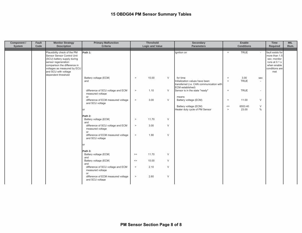
Component / Fault Monitor Strategy Primary Malfunction Secondary Time MILSystem Code Description Criteria Parameters Required Illum.
Threshold EnableLogic and Value Conditions
Plausibility check of the PMSensor Sensor Control Unit(SCU) battery supply duringsensor regeneration:comparison the difference involtages as measured by ECUand SCU with voltagedependent threshold
Path 1: Ignition on = TRUE -
Battery voltage (ECM) > 15.00 V for time = 3.00 secand Initialization values have been
transferred (i.e. CAN communication withECM established)
= TRUE -
difference of SCU voltage and ECMmeasured voltage
> 1.10 V Sensor is in the state "ready" = TRUE -
or meansdifference of ECM measured voltageand SCU voltage
> 3.00 V Battery voltage (ECM) = 11.00 V
Battery voltage (ECM) <= 6553.40 Vor Heater duty cycle of PM Sensor > 23.00 %
Path 2:Battery voltage (ECM) > 11.70 Vand
difference of SCU voltage and ECMmeasured voltage
> 3.00 V
ordifference of ECM measured voltageand SCU voltage
> 1.90 V
or
Path 3:Battery voltage (ECM) >= 11.70 VandBattery voltage (ECM) <= 15.00 Vand
difference of SCU voltage and ECMmeasured voltage
> 2.10 V
ordifference of ECM measured voltageand SCU voltage
> 2.60 V
fault exists formore than 1.5sec; monitorruns at 0.1 swhen enable
conditions aremet
15 OBDG04 PM Sensor Summary Tables
PM Sensor Section Page 8 of 8

Component / State or Status Description of State or StatusSystem Sub-Grouping found in 15OBDG05
ECM Operating States Engine Pre-Drive processor operating normally = TRUE -ignition on = FALSE -processor powerup boot initialization = complete -
orkey off bookkeeping cleanup = complete -( accessory, post-wake-up, pre-sleep)
Engine Running ignition on = TRUE -(see Look-Up table #81) engine speed >= 200.00 rpm
engine speed was at start > 850 rpm
Engine Post-Drive/ Afterun processor operating normally = TRUE -also includes ignition on = FALSE -
"engine stopping" key off bookkeeping cleanup = in process -during engine spin down
Engine Operating Modes Exhaust Operating Mode Normal Mode
Particulate Filter Regeneration Mode
Particulate Filter Regen Service Mode
Defined by:Enable
Conditions
15 OBDG04 ECM Parameter Definition Tables
ECM Parameter Definition Tables Page 1 of 67

Component / State or Status Description of State or StatusSystem Sub-Grouping found in 15OBDG05
Defined by:Enable
Conditions
Exhaust Gas Recirculation (EGR) Exhaust Gas Recirculation (EGR) EGR controller is active
Control is enabled continuously with exceptionsfor failures detectedEGR controller is active
OverrunLong IdleTransmission Gear ShiftCold Startextreme temperature or pressureCritical Regeneration Modes
Overrun
Gear Shifting
Overlong Idle
permanent control deviation
Demand of the drift compensation
System error
Error exhaust gas recirculation valve
Error throttle valve
Engine Brake Status
Atmospheric pressure too low
Battery voltage too low
15 OBDG04 ECM Parameter Definition Tables
ECM Parameter Definition Tables Page 2 of 67

Component / State or Status Description of State or StatusSystem Sub-Grouping found in 15OBDG05
Defined by:Enable
ConditionsSwitch-off coordinator
Environmental temperature too low
Environmental temperature too high
Engine temperature too low
Engine temperature too high
Cold start
Injection quantity too large
Operating-mode coordinator
Rich Idle
External control intervention
Rich Idle Regen
Environmental Temperature too low inRegeneration
EGR Stroking
EGR controller is active in Overrun(warm exhaust system)
EGR controller is active in Overrun(Cold exhaust system)
AFS Faults
Request via SCR monitoring (NOxsensor plausibility check)
15 OBDG04 ECM Parameter Definition Tables
ECM Parameter Definition Tables Page 3 of 67

Component / State or Status Description of State or StatusSystem Sub-Grouping found in 15OBDG05
Defined by:Enable
ConditionsAtmospheric Pressure too low inRegeneration
Engine Temperature too low inRegeneration
Engine Temperature too high inRegeneration
Engine Position Management Engine Position Sync Complete synchronization completedconsisting of:
crankshaft sensor pulses receivedcamshaft sensor pulse received
and aligned properlyor sync via crank only invoked
then crankshaft rotations >= 4.00 counts
Fuel System Fuel System is in Fuel Shut Off engine running = TRUE -also known as required actual engine torque < 1.00 Nm
Decel Fuel Shut Off or Over-Run
Status of Diesel Fuel Refill Detection ((Filtered total fuel volume available > (a) + (b) -
with(a) Amount of fuel volume change thatindicates a refueling event occurred
= 25.26 %
and
15 OBDG04 ECM Parameter Definition Tables
ECM Parameter Definition Tables Page 4 of 67
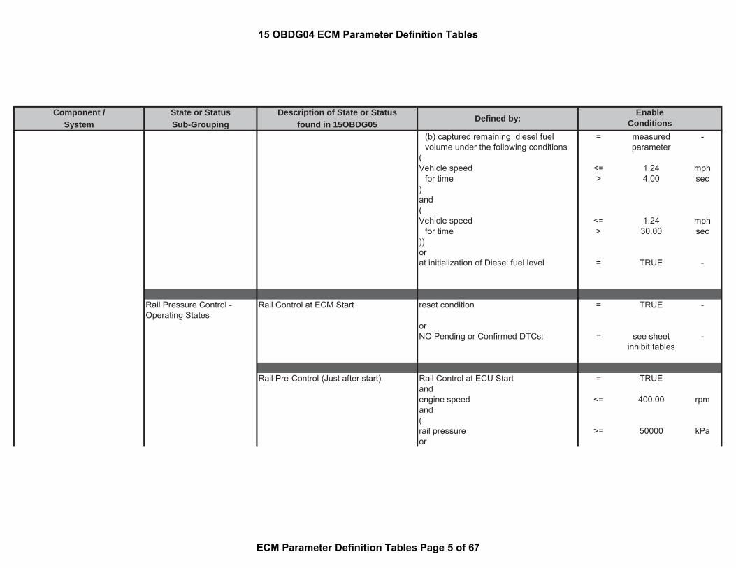
Component / State or Status Description of State or StatusSystem Sub-Grouping found in 15OBDG05
Defined by:Enable
Conditions(b) captured remaining diesel fuelvolume under the following conditions
= measuredparameter
-
(Vehicle speed <= 1.24 mph
for time > 4.00 sec)and(Vehicle speed <= 1.24 mph
for time > 30.00 sec))orat initialization of Diesel fuel level = TRUE -
Rail Pressure Control -Operating States
Rail Control at ECM Start reset condition = TRUE -
orNO Pending or Confirmed DTCs: = see sheet
inhibit tables-
Rail Pre-Control (Just after start) Rail Control at ECU Start = TRUEandengine speed <= 400.00 rpmand(rail pressure >= 50000 kPaor
15 OBDG04 ECM Parameter Definition Tables
ECM Parameter Definition Tables Page 5 of 67

Component / State or Status Description of State or StatusSystem Sub-Grouping found in 15OBDG05
Defined by:Enable
Conditions(a) - (b) < 1000 kPa
and with(a)Fuel Rail Pressure Setpoint = measured
parameter-
and(b)Maximum Rail Pressure for last10ms
= measuredparameter
-
)
Rail Control - PCV Closed Loop ControlOnly
(
Rail Pressure Precontrol (Just after start) = TRUE -
PCV = Pressure Control Valve andNumber of Crankshaft revolutions sinceentering Rail Pressure Precontrol
>= 10.00 revs
)or(state machine rail pressure controltransitioning pressure control valve mode
= TRUE -
andsetpoint volume flow of the metering unitout of rail pressure control (see Look-Up-Table #7)
> 20000 to 33080 mm3/sec
)or
15 OBDG04 ECM Parameter Definition Tables
ECM Parameter Definition Tables Page 6 of 67

Component / State or Status Description of State or StatusSystem Sub-Grouping found in 15OBDG05
Defined by:Enable
Conditions(Fuel system pressure and high pressurepump outlet
< 0.00 kPa
andengine status = RUNNING -)
Rail Control - Metering Unit Closed LoopControl
state machine rail pressure control equaltransitioning to metering unit pressurecontrol mode
= TRUE -
andController for PCV not wound-up (largecorrective control)
= TRUE -
Rail Control - Metering Unit + PCVClosed Loop Control
state machine rail pressure controltransitioning to coupled pressure controlmode (rail pressure is controlled bymetering unit and pressure control valve)
= TRUE -
and(a) + (b) (see Look-Up-Table #8) < 9 to 26 mm^3/re
vand with(a)Torque Generating fuel injectionquantity
= calculatedparameter
-
and
15 OBDG04 ECM Parameter Definition Tables
ECM Parameter Definition Tables Page 7 of 67

Component / State or Status Description of State or StatusSystem Sub-Grouping found in 15OBDG05
Defined by:Enable
Conditions(b)Non-Torque generating fuel injectionquantity
= calculatedparameter
-
Switchover Between Metering Unit + PCVClosed Loop Control to Metering UnitClosed Loop Control only
(
state machine rail pressure control equalto pressure control valve
= TRUE -
orstate machine rail pressure controltransitioning pressure control valve mode
= TRUE -
)and(a) + (b) < (c) + (d) -
(a)Torque Generating fuel injectionquantity
= calculatedparameter
-
(b)Non-Torque generating fuel injectionquantity
= calculatedparameter
-
(c) (see Look-Up-Table #8) = 9 to 26 mm^3/rev
(d) = 2.00 mm^3/rev
andNO Pending or Confirmed DTCs: = see sheet
inhibit tables-
15 OBDG04 ECM Parameter Definition Tables
ECM Parameter Definition Tables Page 8 of 67

Component / State or Status Description of State or StatusSystem Sub-Grouping found in 15OBDG05
Defined by:Enable
Conditionsor(state machine rail pressure control equalto metering unit control mode
= TRUE -
orstate machine rail pressure control equaltransitioning to metering unit pressurecontrol mode
= TRUE -
)andNO Pending or Confirmed DTCs: = see sheet
inhibit tables-
(Fuel system pressure and high pressurepump outlet
< 0.00 kPa
andengine status = RUNNING -))andNO Pending or Confirmed DTCs: = see sheet
inhibit tables-
)
Switchover between PCV or MeteringUnit closed loop control to Metering Unit+ PCV Closed Loop Control
(
15 OBDG04 ECM Parameter Definition Tables
ECM Parameter Definition Tables Page 9 of 67

Component / State or Status Description of State or StatusSystem Sub-Grouping found in 15OBDG05
Defined by:Enable
Conditionsstate machine rail pressure control equalto pressure control valve
= TRUE -
orstate machine rail pressure control equalcoupled pressure control (rail pressure iscontrolled by metering unit and pressurecontrol valve)
= TRUE -
orstate machine rail pressure controltransitioning pressure control valve mode
= TRUE -
orstate machine rail pressure control equaltransitioning to metering unit pressurecontrol mode
= TRUE -
)and((exhaust gas system regeneration mode != REGEN -
)andNO Pending or Confirmed DTCs: = see sheet
inhibit tables-
15 OBDG04 ECM Parameter Definition Tables
ECM Parameter Definition Tables Page 10 of 67

Component / State or Status Description of State or StatusSystem Sub-Grouping found in 15OBDG05
Defined by:Enable
ConditionsSwitchover Between Metering Unit + PCVClosed Loop Control to PCV Closed LoopControl only
(
state machine rail pressure controlequals coupled pressure control (railpressure is controlled by metering unitand pressure control valve)
= TRUE -
orstate machine rail pressure controltransitioning to coupled pressure controlmode (rail pressure is controlled bymetering unit and pressure control valve)
= TRUE -
)and(a) + (b) (see Look-Up-Table #8) < 9 to 26 mm^3/re
vwith(a)Torque Generating fuel injectionquantity
= calculatedparameter
-
and(b)Non-Torque generating fuel injectionquantity
= calculatedparameter
-
Idle Speed Control Idle Speed Controller Active no overrides for:"normal" low idle speed governor Gear-Shift Harmonization
Intrusive Diagnosis Action
15 OBDG04 ECM Parameter Definition Tables
ECM Parameter Definition Tables Page 11 of 67

Component / State or Status Description of State or StatusSystem Sub-Grouping found in 15OBDG05
Defined by:Enable
Conditions
A/F Sensor A/F sensor error status bit A/F SPI communication error A/F SPI communication error = TRUE -A/F Sensor heater powerstage error HO2S Heater Control Circuit Bank 1
Sensor 1 Circuit High= TRUE -
orHO2S Heater Control Circuit Bank 1Sensor 1 Circuit Low
= TRUE -
orHO2S Heater Control Circuit Bank 1Sensor 1 Circuit
= TRUE -
A/F sensor short circuit to battery ofsensor lines or A/F sensor short circuit toground of sensor lines error detected
A/F sensor short circuit to battery ofsensor lines
= TRUE -
orA/F sensor short circuit to ground ofsensor lines
= TRUE -
Open load detected at sensor lines UN(A/F sensor nernst cell) or VG (A/Fsensor virtual ground)
A/F Sensor Reference VoltageCircuit/Open Bank 1 Sensor 1
= TRUE -
orA/F Sensor Negative Current ControlCircuit/Open Bank 1 Sensor 1
= TRUE -
A/F sensor signal range check error A/F sensor Circuit Range/PerformanceBank 1 Sensor 1
= TRUE -
15 OBDG04 ECM Parameter Definition Tables
ECM Parameter Definition Tables Page 12 of 67

Component / State or Status Description of State or StatusSystem Sub-Grouping found in 15OBDG05
Defined by:Enable
ConditionsA/F signal calibration error A/F sensor calibration resistor circuit
output high= TRUE -
orA/F sensor calibration resistor circuitoutput low
= TRUE -
A/F sensor calibration error of resistancesignal
A/F sensor calibration resistance max = TRUE -
orA/F sensor calibration resistance min = TRUE -
A/F sensor heater control deviation error A/F sensor Heater Resistance Bank1Sensor 1 high
= TRUE -
orA/f sensor Heater Resistance Bank1Sensor 1 low
= TRUE -
A/F sensor open load at input pumpcurrent line
A/F Sensor Positive Current ControlCircuit/Open Bank 1 Sensor 1
= TRUE -
A/F sensor plausibility error at differentengine conditions
A/F Sensor Performance - Signal Highduring Deceleration Bank 1 Sensor 1
= TRUE -
orO2 Sensor Performance - Signal lowduring Deceleration Bank 1 Sensor 1
= TRUE -
orO2 Sensor Performance - Signal Highduring Moderate Load Sensor 1
= TRUE -
orA/F Sensor Performance - Signal Lowduring Moderate Load Bank 1 Sensor 1
= TRUE -
A/F sensor dynamic error A/F Sensor Circuit Slow Response Bank1 Sensor 1
= TRUE -
15 OBDG04 ECM Parameter Definition Tables
ECM Parameter Definition Tables Page 13 of 67

Component / State or Status Description of State or StatusSystem Sub-Grouping found in 15OBDG05
Defined by:Enable
Conditions
Status bit for valid A/Fsensor inner Resistance
Status bit for valid A/F sensor innerResistance
No Permanent wire errors are present(Short circuit to battery, short circuit toground and open load)
= TRUE -
No permanent Resistance calibrationvalue error
= TRUE -
No Errors in CJ125 SPI communicationand no low battery voltage detected byCJ125
= TRUE -
Dewpoint Detection A/F Sensor Dewpoint Reached Integrated heat quantity (see Look-Up-Table #1)
>= 130 to 600 kJ
andNO Pending or Confirmed DTCs: (relatedto A/F sensor heater circuit or A/F sensorcircuit used for sensor internal resistancecalculation)
= see sheetinhibit tables
-
Upstream NOx Sensor Status of NOx signal of upstream NOxsensor
15 OBDG04 ECM Parameter Definition Tables
ECM Parameter Definition Tables Page 14 of 67

Component / State or Status Description of State or StatusSystem Sub-Grouping found in 15OBDG05
Defined by:Enable
Conditions(following condition met for time: > 30.00 sec
(Integrated heat quantity (see Look-Up-Table #1)
>= 130 to 600 kJ
NOx status signal received via CANmessage (Please see the definition)
= TRUE -
for time > 1 seccalculated lambda value based on airmass flow and injection quantity
> 0.90 -
for time > 2 secengine speed > 200.00 rpmfor time > 20.00 secNO Pending or Confirmed DTCs: = see sheet
inhibit tables-
))
Upstream NOx sensor dewpoint achieved Integrated heat quantity (see Look-Up-Table #1)
>= 130 to 600 kJ
Downstream NOx Sensor Status of NOx signal of downstream NOxsensor
(following condition met for time: > 30.00 sec
(
15 OBDG04 ECM Parameter Definition Tables
ECM Parameter Definition Tables Page 15 of 67

Component / State or Status Description of State or StatusSystem Sub-Grouping found in 15OBDG05
Defined by:Enable
ConditionsIntegrated heat quantity (see Look-Up-Table #3)
>= 310 to 1460 kJ
NOx status signal received via CANmessage (Please see the definition)
= TRUE -
for time > 1 seccalculated lambda value based on airmass flow and injection quantity
> 0.90 -
for time > 2 secengine speed > 200.00 rpmfor time > 20.00 secNO Pending or Confirmed DTCs: = see sheet
inhibit tables-
))
Downstream NOx sensor dewpointachieved
Integrated heat quantity (see Look-Up-Table #3)
>= 310 to 1460 kJ
Enabling Downstream NOx sensor heaterdiagnosis
(SCR Catalyst downstream temperature >= 99.96 °C
SCR Catalyst downstream temperature <= 599.96 °C
battery voltage >= 11.00 V
15 OBDG04 ECM Parameter Definition Tables
ECM Parameter Definition Tables Page 16 of 67

Component / State or Status Description of State or StatusSystem Sub-Grouping found in 15OBDG05
Defined by:Enable
Conditionsbattery voltage <= 655.34 V
andIntegrated heat quantity (see Look-Up-Table #3)
>= 310 to 1460 kJ
for time > 30.00 sec)and
for time > 0.5 secNO Pending or Confirmed DTCs: = see sheet
inhibit tables-
PM Sensor PM sensor dewpoint achieved Integrated heat quantity (see Look-Up-Table #3)
>= 310 to 1460 kJ
Regeneration of the DieselParticulate Filter
Status thermal regeneration active
Reduced particle mass flow in simulationby thermal regeneration(a) * (b) * ( c) > 0 -
with(a) Correction factor for thermal sootburn-out dependent on lambda andoxygen mass flow (see Look-Up-Table#5)
= 0 to 1.619995 factor
15 OBDG04 ECM Parameter Definition Tables
ECM Parameter Definition Tables Page 17 of 67

Component / State or Status Description of State or StatusSystem Sub-Grouping found in 15OBDG05
Defined by:Enable
Conditions(b) Effect of temperature onregenerated particle mass (see Look-Up-Table #6)
= 0 to 0.949951 -
( c) Basis value of produced soot massflow dependent on actual soot mass(see Look-Up-Table #4)
= 0.013 to 0.054 g/sec
Release of dosing of the dosing strategy
status of SCR control state (please seethe definition)
= MeteringControl
-
Reductant dosing is released = TRUE -Deactivation of dosing to execute theNOx Offset test (Please see thedefinition)
= FALSE -
since start for time >= 0.00 secgradient of exhaust gas temperature <= -100 °C/sec
since start for time >= 42949672.95 secAverage temperature inside the SCRcatalyst:
> 159.96 °C
SCR catalyst wall temperature > 3003.56 °CVehicle speed >= 203.648228713
487mph
engine speed > 550.00 rpmNO Pending or Confirmed DTCs: = see sheet
inhibit tables-
SCR System NOx Control SystemReductant Dosing StrategyActive State
15 OBDG04 ECM Parameter Definition Tables
ECM Parameter Definition Tables Page 18 of 67

Component / State or Status Description of State or StatusSystem Sub-Grouping found in 15OBDG05
Defined by:Enable
Conditionsignition = on -
State of Reductant Pressure ControlSystem: Standby
Dwell time in the state of standby < 2.10 sec
NO Pending or Confirmed DTCs: = see sheetinhibit tables
-
State of Reductant Pressure ControlSystem: No Pressure control
Old SCR control state (please see thedefinition)
= Stand by -
ignition = on -Dwell time in the state of standby >= 2.10 secDwell time in the state of no pressurecontrol
< 2.00 sec
NO Pending or Confirmed DTCs: = see sheetinhibit tables
-
State of Reductant Pressure ControlSystem: Pressure control
Old SCR control state (please see thedefinition)
= NO PressureControl
-
ignition = on -engine speed > 600.00 rpmDwell time in the state of no pressurecontrol
>= 2.00 sec
exhaust gas temperature Upstream SCR >= 179.96 °C
(Reductant Defrost check (please see thedefinition)
= TRUE -
NOx Control SystemReductant Dosing PressureControl System States
15 OBDG04 ECM Parameter Definition Tables
ECM Parameter Definition Tables Page 19 of 67

Component / State or Status Description of State or StatusSystem Sub-Grouping found in 15OBDG05
Defined by:Enable
ConditionsorThe component protection release of theheater control (please see the definition)
= TRUE -
orPreliminary release of the heater controlfor themain state machine (please see thedefinition)
= TRUE -
)NO Pending or Confirmed DTCs: = see sheet
inhibit tables-
State of Reductant Pressure ControlSystem: Refilling Reductant in pressureline (substate of Pressure control)
SCR control state (please see thedefinition)
= PressureControl
-
(Reductant filling state in the pressure line < 70.00 %
andReductant Pump Module Pressure < 95.00 kPa)Set-point duty cycle for Reductant dosingvalve
= 100.00 %
Set-point duty cycle for the ReductantPump pressure Motor actuator
= 60.00 %
15 OBDG04 ECM Parameter Definition Tables
ECM Parameter Definition Tables Page 20 of 67

Component / State or Status Description of State or StatusSystem Sub-Grouping found in 15OBDG05
Defined by:Enable
ConditionsNO Pending or Confirmed DTCs: = see sheet
inhibit tables-
State of Reductant Pressure ControlSystem: Pressure build up (substate ofPressure control)
SCR control state (please see thedefinition)
= PressureControl
-
(Reductant filling state in the pressure line >= 70.00 %
orReductant Pump Module Pressure >= 95.00 kPafor time > 0.50 sec)
Reductant Pump Module Pressure < 375.00 kPaSet-point duty cycle for Reductant dosingvalve
= 0% %
Set-point duty cycle for the ReductantPump pressure Motor actuator
= 40.00 %
NO Pending or Confirmed DTCs: = see sheetinhibit tables
-
State of Reductant Pressure ControlSystem: Ventilation (substate of Pressurecontrol)
SCR control state (please see thedefinition)
= PressureControl
-
Reductant Pump Module Pressure < 375.00 kPa
15 OBDG04 ECM Parameter Definition Tables
ECM Parameter Definition Tables Page 21 of 67

Component / State or Status Description of State or StatusSystem Sub-Grouping found in 15OBDG05
Defined by:Enable
ConditionsDwell time in Pressure Build up substate > 15.00 sec
system pressurizes in pressure buildupand ventilation states
< 10.00 counts
Set-point duty cycle for Reductant dosingvalve
= 0.00 %
Set-point duty cycle for the ReductantPump pressure Motor actuator
= 40.00 %
Dwell time in the sub state ventilation < 0.30 secNO Pending or Confirmed DTCs: = see sheet
inhibit tables-
State of Reductant Pressure ControlSystem: Metering control (substate ofPressure control)
SCR control state (please see thedefinition)
= PressureControl
-
Reductant Pump Module Pressure >= 375.00 kPaSet-point duty cycle for Reductant dosingvalve
= 0 %
NO Pending or Confirmed DTCs: = see sheetinhibit tables
-
State of Reductant Pressure ControlSystem: Pressure reduction
ignition = off -
dwell time in the state of pressurereduction
< 20.00 sec
15 OBDG04 ECM Parameter Definition Tables
ECM Parameter Definition Tables Page 22 of 67
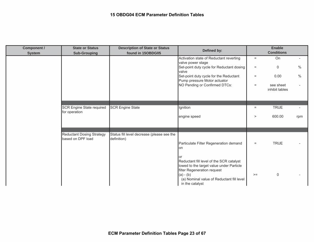
Component / State or Status Description of State or StatusSystem Sub-Grouping found in 15OBDG05
Defined by:Enable
ConditionsActivation state of Reductant revertingvalve power stage
= On -
Set-point duty cycle for Reductant dosingvalve
= 0 %
Set-point duty cycle for the ReductantPump pressure Motor actuator
= 0.00 %
NO Pending or Confirmed DTCs: = see sheetinhibit tables
-
SCR Engine State requiredfor operation
SCR Engine State Ignition = TRUE -
engine speed > 600.00 rpm
Reductant Dosing Strategybased on DPF load
Status fill level decrease (please see thedefinition)
Particulate Filter Regeneration demandon
= TRUE -
orReductant fill level of the SCR catalystlowed to the target value under Particlefilter Regeneration request(a) - (b) >= 0 -
(a) Nominal value of Reductant fill levelin the catalyst
15 OBDG04 ECM Parameter Definition Tables
ECM Parameter Definition Tables Page 23 of 67
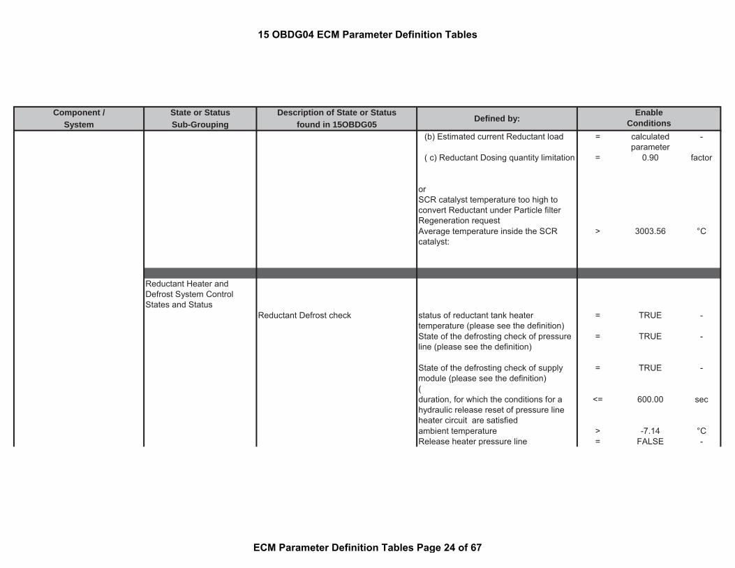
Component / State or Status Description of State or StatusSystem Sub-Grouping found in 15OBDG05
Defined by:Enable
Conditions(b) Estimated current Reductant load = calculated
parameter-
( c) Reductant Dosing quantity limitation = 0.90 factor
orSCR catalyst temperature too high toconvert Reductant under Particle filterRegeneration requestAverage temperature inside the SCRcatalyst:
> 3003.56 °C
Reductant Heater andDefrost System ControlStates and Status
Reductant Defrost check status of reductant tank heatertemperature (please see the definition)
= TRUE -
State of the defrosting check of pressureline (please see the definition)
= TRUE -
State of the defrosting check of supplymodule (please see the definition)
= TRUE -
(duration, for which the conditions for ahydraulic release reset of pressure lineheater circuit are satisfied
<= 600.00 sec
ambient temperature > -7.14 °CRelease heater pressure line = FALSE -
15 OBDG04 ECM Parameter Definition Tables
ECM Parameter Definition Tables Page 24 of 67
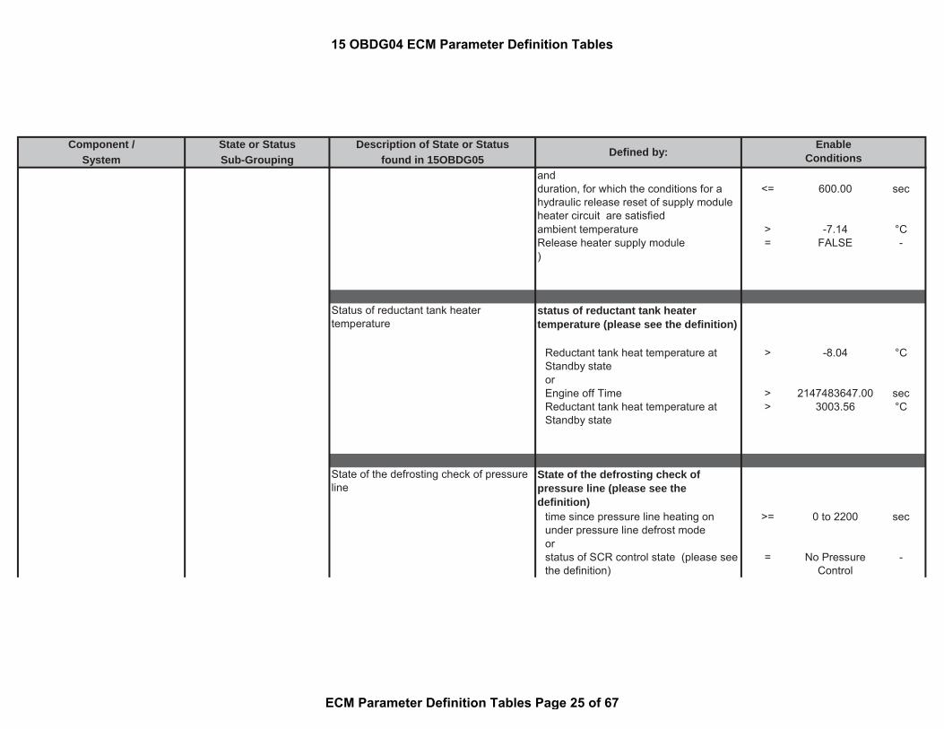
Component / State or Status Description of State or StatusSystem Sub-Grouping found in 15OBDG05
Defined by:Enable
Conditionsandduration, for which the conditions for ahydraulic release reset of supply moduleheater circuit are satisfied
<= 600.00 sec
ambient temperature > -7.14 °CRelease heater supply module = FALSE -)
Status of reductant tank heatertemperature
status of reductant tank heatertemperature (please see the definition)
Reductant tank heat temperature atStandby state
> -8.04 °C
orEngine off Time > 2147483647.00 secReductant tank heat temperature atStandby state
> 3003.56 °C
State of the defrosting check of pressureline
State of the defrosting check ofpressure line (please see thedefinition)
time since pressure line heating onunder pressure line defrost mode
>= 0 to 2200 sec
orstatus of SCR control state (please seethe definition)
= No PressureControl
-
15 OBDG04 ECM Parameter Definition Tables
ECM Parameter Definition Tables Page 25 of 67

Component / State or Status Description of State or StatusSystem Sub-Grouping found in 15OBDG05
Defined by:Enable
ConditionsPressure line defrost timer = 0 secorignition = on secengine speed > 600.00 rpm(Pressure line defrost check in lastdriving cycle
= TRUE -
status of SCR control state (please seethe definition)
= No PressureControl
-
Engine off Time (see Look-Up-Table#21)
< 120 to 900 sec
NO Pending or Confirmed DTCs: = TRUE -
State of the defrosting check of supplymodule
State of the defrosting check of supplymodule (please see the definition)
time since supply module heating onunder supply module defrost mode
>= 0 to 2200 sec
orstatus of SCR control state (please seethe definition)
= No PressureControl
-
Supply module defrost timer = 0 secorignition = on secengine speed > 600.00 rpm(Pressure line defrost check in lastdriving cycle
= TRUE -
15 OBDG04 ECM Parameter Definition Tables
ECM Parameter Definition Tables Page 26 of 67
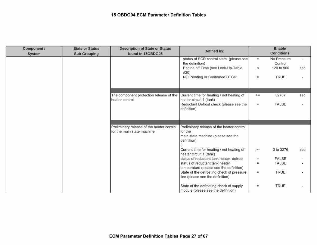
Component / State or Status Description of State or StatusSystem Sub-Grouping found in 15OBDG05
Defined by:Enable
Conditionsstatus of SCR control state (please seethe definition)
= No PressureControl
-
Engine off Time (see Look-Up-Table#20)
< 120 to 900 sec
NO Pending or Confirmed DTCs: = TRUE -
The component protection release of theheater control
Current time for heating / not heating ofheater circuit 1 (tank)
>= 32767 sec
Reductant Defrost check (please see thedefinition)
= FALSE -
Preliminary release of the heater controlfor the main state machine
Preliminary release of the heater controlfor themain state machine (please see thedefinition)(Current time for heating / not heating ofheater circuit 1 (tank)
>= 0 to 3276 sec
status of reductant tank heater defrost = FALSE -status of reductant tank heatertemperature (please see the definition)
= FALSE -
State of the defrosting check of pressureline (please see the definition)
= TRUE -
State of the defrosting check of supplymodule (please see the definition)
= TRUE -
15 OBDG04 ECM Parameter Definition Tables
ECM Parameter Definition Tables Page 27 of 67

Component / State or Status Description of State or StatusSystem Sub-Grouping found in 15OBDG05
Defined by:Enable
Conditions)or(ignition = on secengine speed > 600.00 rpmEngine off Time <= 0.00 secState of the defrosting check of pressureline (please see the definition)
= TRUE -
State of the defrosting check of supplymodule (please see the definition)
= TRUE -
andif the following conditions were met inprevious driving cycle
= TRUE -
(ignition = on secengine speed > 600.00 rpmEngine off Time <= 0.00 secState of the defrosting check of pressureline (please see the definition)
= TRUE -
State of the defrosting check of supplymodule (please see the definition)
= TRUE -
))
Release of tank heater circuit (
15 OBDG04 ECM Parameter Definition Tables
ECM Parameter Definition Tables Page 28 of 67

Component / State or Status Description of State or StatusSystem Sub-Grouping found in 15OBDG05
Defined by:Enable
ConditionsRequested defrosting time for Reductanttank heater (see Look-Up-Table #24)
>= 10 to 4170 sec
orRequested heating time for Reductanttank heater (see Look-Up-Table #17)
>= 0 to 300 sec
)
or((Requested defrosting time for Reductanttank heater (see Look-Up-Table #24)
>= 10 to 4170 sec
orRequested heating time for Reductanttank heater (see Look-Up-Table #17)
>= 0 to 300 sec
)and(Requested defrosting time for pressureline heater (see Look-Up-Table #18)
>= 0 to 2200 sec
orRequested heating time for pressure lineheater (see Look-Up-Table #22)
>= 0 to 180 sec
))
or((
15 OBDG04 ECM Parameter Definition Tables
ECM Parameter Definition Tables Page 29 of 67

Component / State or Status Description of State or StatusSystem Sub-Grouping found in 15OBDG05
Defined by:Enable
ConditionsRequested defrosting time for Reductanttank heater (see Look-Up-Table #24)
>= 10 to 4170 sec
orRequested heating time for Reductanttank heater (see Look-Up-Table #17)
>= 0 to 300 sec
)and(Requested defrosting time for supplymodule heater (see Look-Up-Table #19)
>= 0 to 2200 sec
orRequested heating time for supplymodule heater (see Look-Up-Table #23)
>= 0 to 180 sec
))
or((Requested defrosting time for Reductanttank heater (see Look-Up-Table #24)
>= 10 to 4170 sec
orRequested heating time for Reductanttank heater (see Look-Up-Table #17)
>= 0 to 300 sec
)and(
15 OBDG04 ECM Parameter Definition Tables
ECM Parameter Definition Tables Page 30 of 67

Component / State or Status Description of State or StatusSystem Sub-Grouping found in 15OBDG05
Defined by:Enable
ConditionsRequested defrosting time for pressureline heater (see Look-Up-Table #18)
>= 0 to 2200 sec
orRequested heating time for pressure lineheater (see Look-Up-Table #22)
>= 0 to 180 sec
)and(Requested defrosting time for supplymodule heater (see Look-Up-Table #19)
>= 0 to 2200 sec
orRequested heating time for supplymodule heater (see Look-Up-Table #23)
>= 0 to 180 sec
))
andNO Pending or Confirmed DTCs: = TRUE -
Release of pressure line heater circuit (Requested defrosting time for pressureline heater (see Look-Up-Table #18)
>= 0 to 2200 sec
orRequested heating time for pressure lineheater (see Look-Up-Table #22)
>= 0 to 180 sec
15 OBDG04 ECM Parameter Definition Tables
ECM Parameter Definition Tables Page 31 of 67

Component / State or Status Description of State or StatusSystem Sub-Grouping found in 15OBDG05
Defined by:Enable
Conditions)
or((Requested defrosting time for pressureline heater (see Look-Up-Table #18)
>= 0 to 2200 sec
orRequested heating time for pressure lineheater (see Look-Up-Table #22)
>= 0 to 180 sec
)and(Requested defrosting time for supplymodule heater (see Look-Up-Table #19)
>= 0 to 2200 sec
orRequested heating time for supplymodule heater (see Look-Up-Table #23)
>= 0 to 180 sec
))
andNO Pending or Confirmed DTCs: = see sheet
inhibit tables-
Release of tank heater circuit (
15 OBDG04 ECM Parameter Definition Tables
ECM Parameter Definition Tables Page 32 of 67
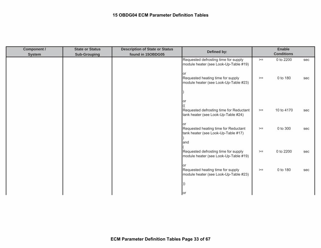
Component / State or Status Description of State or StatusSystem Sub-Grouping found in 15OBDG05
Defined by:Enable
ConditionsRequested defrosting time for supplymodule heater (see Look-Up-Table #19)
>= 0 to 2200 sec
orRequested heating time for supplymodule heater (see Look-Up-Table #23)
>= 0 to 180 sec
)
or((Requested defrosting time for Reductanttank heater (see Look-Up-Table #24)
>= 10 to 4170 sec
orRequested heating time for Reductanttank heater (see Look-Up-Table #17)
>= 0 to 300 sec
)and(Requested defrosting time for supplymodule heater (see Look-Up-Table #19)
>= 0 to 2200 sec
orRequested heating time for supplymodule heater (see Look-Up-Table #23)
>= 0 to 180 sec
))
or
15 OBDG04 ECM Parameter Definition Tables
ECM Parameter Definition Tables Page 33 of 67

Component / State or Status Description of State or StatusSystem Sub-Grouping found in 15OBDG05
Defined by:Enable
Conditions((Requested defrosting time for pressureline heater (see Look-Up-Table #18)
>= 0 to 2200 sec
orRequested heating time for pressure lineheater (see Look-Up-Table #22)
>= 0 to 180 sec
)and(Requested defrosting time for supplymodule heater (see Look-Up-Table #19)
>= 0 to 2200 sec
orRequested heating time for supplymodule heater (see Look-Up-Table #23)
>= 0 to 180 sec
))or((Requested defrosting time for Reductanttank heater (see Look-Up-Table #24)
>= 10 to 4170 sec
orRequested heating time for Reductanttank heater (see Look-Up-Table #17)
>= 0 to 300 sec
)and(
15 OBDG04 ECM Parameter Definition Tables
ECM Parameter Definition Tables Page 34 of 67

Component / State or Status Description of State or StatusSystem Sub-Grouping found in 15OBDG05
Defined by:Enable
ConditionsRequested defrosting time for pressureline heater (see Look-Up-Table #18)
>= 0 to 2200 sec
orRequested heating time for pressure lineheater (see Look-Up-Table #22)
>= 0 to 180 sec
)and(Requested defrosting time for supplymodule heater (see Look-Up-Table #19)
>= 0 to 2200 sec
orRequested heating time for supplymodule heater (see Look-Up-Table #23)
>= 0 to 180 sec
))
andNO Pending or Confirmed DTCs: = see sheet
inhibit tables-
Status of the battery voltage being in thevalid working range for Reductant tankheater
battery voltage < 655.34 Vbattery voltage > 11.00 V
for time > 2.00 sec
15 OBDG04 ECM Parameter Definition Tables
ECM Parameter Definition Tables Page 35 of 67

Component / State or Status Description of State or StatusSystem Sub-Grouping found in 15OBDG05
Defined by:Enable
Conditions
Status of the battery voltage being in thevalid working range for pressure lineheater
battery voltage < 655.34 Vbattery voltage > 11.00 V
for time > 2.00 sec
Status of Reductant Tank HeaterRelease
(status of reductant tank heatertemperature (please see the definition)
= TRUE -
Waiting time after tank heater releaseexpired
> 0 sec
)
or((Waiting time before tank heater released < 32767.00 sec
started withstatus of reductant tank heatertemperature (please see the definition)
= FALSE -
)and
15 OBDG04 ECM Parameter Definition Tables
ECM Parameter Definition Tables Page 36 of 67

Component / State or Status Description of State or StatusSystem Sub-Grouping found in 15OBDG05
Defined by:Enable
Conditions(status of reductant tank heatertemperature (please see the definition)
= TRUE -
Waiting time after tank heater releaseexpired
> 0 sec
))
or((Waiting time before tank heater released > 32767.00 sec
started withstatus of reductant tank heatertemperature (please see the definition)
= FALSE -
)and(status of reductant tank heatertemperature (please see the definition)
= TRUE -
Waiting time after tank heater releaseexpired
> 0.00 sec
))
Reductant Tank LevelSystem States and Status
status of Reductant tank level Tank level > full (100%) = Full -
Warning (66.67%) < tank level < full(100%)
= OK -
15 OBDG04 ECM Parameter Definition Tables
ECM Parameter Definition Tables Page 37 of 67

Component / State or Status Description of State or StatusSystem Sub-Grouping found in 15OBDG05
Defined by:Enable
ConditionsRestriction (33.33%) < tank level <Warning (66.67%)
= Warning -
Empty < tank level < Restriction (33.33%) = Restriction -
Tank level < = 0.1% = Empty -
Status of Reductant tank level reset whenrefilling is detected (please see thedefinition)
(
time since potential Reductant refilldetection is set
>= 8.00 sec
and with(Derivation of the PT1 filtered level signal(DT1)
>= 1.00 %/sec
ignition = on -engine speed > 600.00 rpmVehicle speed >= 6.22 mphtime since engine started <= (a) * (b)(a) Time period for a positive slope todetect refueling
= 8.00 sec
(b) Factor for the extension of thedetection time for refueling
= 3.00 factor
since the following conditions met: = TRUE -(Falling edge of ignition = TRUE -or
15 OBDG04 ECM Parameter Definition Tables
ECM Parameter Definition Tables Page 38 of 67

Component / State or Status Description of State or StatusSystem Sub-Grouping found in 15OBDG05
Defined by:Enable
ConditionsReductant Refill enabling conditions resettimers
= TRUE -
)))
or(time since potential Reductant refilldetection is set
>= 4.00 sec
and with(Derivation of the PT1 filtered level signal(DT1)
>= 1.00 %/s
filter release for Reductant tank levelcalculation at T15 on (Please see thedefinition)
= TRUE -
and with(Frozen state is active during a certainwarning level (please see the definition)
= TRUE -
and with(Reductant tank Temperature >= -100.04 °CorReductant low warning level (Please seethe definition)
>= 0.00 level
)))
15 OBDG04 ECM Parameter Definition Tables
ECM Parameter Definition Tables Page 39 of 67

Component / State or Status Description of State or StatusSystem Sub-Grouping found in 15OBDG05
Defined by:Enable
ConditionsStatus of Reductant Tank Level Release status of reductant tank level release
(please see the definition)Status of Filter release for reductant tanklevel calculation (please see thedefinition)
= TRUE -
and((ambient temperature >= -100.04 °C((status of reductant tank heatertemperature (please see the definition)
= FALSE -
Waiting time before tank heater released < 32767.00 sec
andstatus of reductant tank heatertemperature (please see the definition)
= TRUE -
Waiting time after tank heater releaseexpired
> 0 sec
)or(status of reductant tank heatertemperature (please see the definition)
= FALSE -
Waiting time before tank heater released >= 32767.00 sec
andstatus of reductant tank heatertemperature (please see the definition)
= TRUE -
Waiting time after tank heater releaseexpired
>= 0.00 sec
15 OBDG04 ECM Parameter Definition Tables
ECM Parameter Definition Tables Page 40 of 67
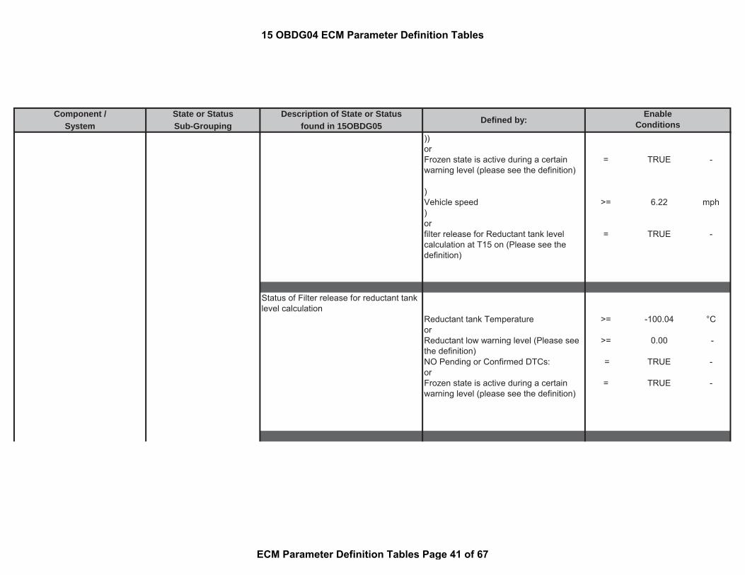
Component / State or Status Description of State or StatusSystem Sub-Grouping found in 15OBDG05
Defined by:Enable
Conditions))orFrozen state is active during a certainwarning level (please see the definition)
= TRUE -
)Vehicle speed >= 6.22 mph)orfilter release for Reductant tank levelcalculation at T15 on (Please see thedefinition)
= TRUE -
Status of Filter release for reductant tanklevel calculation
Reductant tank Temperature >= -100.04 °CorReductant low warning level (Please seethe definition)
>= 0.00 -
NO Pending or Confirmed DTCs: = TRUE -orFrozen state is active during a certainwarning level (please see the definition)
= TRUE -
15 OBDG04 ECM Parameter Definition Tables
ECM Parameter Definition Tables Page 41 of 67

Component / State or Status Description of State or StatusSystem Sub-Grouping found in 15OBDG05
Defined by:Enable
ConditionsFilter release for Reductant tank levelcalculation at Ignition on
ignition = on
Engine on timer is expired (please seethe definition)
= False
Vehicle speed >= 0.62 mphReductant low warning level (Please seethe definition)
>= 49.00 level
and with((Raw Reductant tank level >= 33.3 %and with(Remaining Reductant quantity (a) - (b): < (a) - (b)
(a) Tank level for reserve mode(Restriction level) in [g]
= 1870.00 g
(b) Tank level threshold range belowRestriction threshold for T15 refilldetection release
= 0.00 g
)
orRaw Reductant tank level >= 66.7 %and with(Remaining Reductant quantity (a) - (b): < (a) - (b)
(a) Tank level for reserve mode(Warning level) in [g]
= 5060.00 g
(b) Tank level threshold range belowWARNING threshold for T15 refilldetection release
= 0.00 g
15 OBDG04 ECM Parameter Definition Tables
ECM Parameter Definition Tables Page 42 of 67

Component / State or Status Description of State or StatusSystem Sub-Grouping found in 15OBDG05
Defined by:Enable
Conditions)
orRaw Reductant tank level >= 100 %and with(Remaining Reductant quantity (a) - (b): >= (a) - (b)
(a) Tank level for reserve mode(Warning level) in [g]
= 5060.00 g
(b) Tank level threshold range belowWARNING threshold for T15 refilldetection release
= 0.00 g
))
Status of Refill detection of Reductanttank
Status of Refill detection of Reductanttank (please see the definition)Reductant tank level changed = TRUE -((Captured Reductant tank level at lasttank level change
= Empty -
orCaptured Reductant tank level at lasttank level change
= Restriction -
)and(one or more of following conditions aremet
15 OBDG04 ECM Parameter Definition Tables
ECM Parameter Definition Tables Page 43 of 67

Component / State or Status Description of State or StatusSystem Sub-Grouping found in 15OBDG05
Defined by:Enable
Conditionsstatus of Reductant tank level (pleasesee the definition)
= Warning -
orstatus of Reductant tank level (pleasesee the definition)
= OK -
orstatus of Reductant tank level (pleasesee the definition)
= Full -
))or((Captured Reductant tank level at lasttank level change
= Warning -
orCaptured Reductant tank level at lasttank level change
= OK -
)and(status of Reductant tank level (pleasesee the definition)
= Full -
)or(Captured Reductant tank level at lasttank level change
= OK -
status of Reductant tank level (pleasesee the definition)
= Full -
))
15 OBDG04 ECM Parameter Definition Tables
ECM Parameter Definition Tables Page 44 of 67

Component / State or Status Description of State or StatusSystem Sub-Grouping found in 15OBDG05
Defined by:Enable
Conditions
Engine on timer is expired time since engine started >= (a) * (b) sec(a) calibrated rise timer 12 sec(b) factor 20 -
and with((ignition = on -engine speed > 600.00 rpmVehicle speed >= 6.22 mph)or(Vehicle speed >= 6.22 mphNO Pending or Confirmed DTCs: = TRUE -for time > 1.00 sec))and with timer reset conditions
(Falling edge of ignition = TRUE -orReductant Refill enabling conditionsreset timers
= TRUE -
)
Reducant Tank Level LowWarning States
Normal_Operation_OK: 0 decimal,normal operation
Reductant tank level = Full -
and with
15 OBDG04 ECM Parameter Definition Tables
ECM Parameter Definition Tables Page 45 of 67

Component / State or Status Description of State or StatusSystem Sub-Grouping found in 15OBDG05
Defined by:Enable
Conditions(Warning level <= 49 -or(Previous warning level > 49 -vehicle speed <= 98.18 mph))
orReductant Quality state > 0 -
Warning_Leve1: 1 decimal, Warninglevel 1
Reductant tank level < Full -
Remaining mileage > 1500.00 milesand with(Warning level <= 49 Warning
level indecimal
or(Previous warning level > 49 Warning
level indecimal
vehicle speed <= 98.18 mph))and with
15 OBDG04 ECM Parameter Definition Tables
ECM Parameter Definition Tables Page 46 of 67

Component / State or Status Description of State or StatusSystem Sub-Grouping found in 15OBDG05
Defined by:Enable
ConditionsReductant Quality state = 0 -
Warning_Level2: 2 decimal, Warninglevel 2
Reductant tank level < Full -
Remaining mileage <= 1500.00 milesand with(Warning level <= 49 Warning
level indecimal
or(Previous warning level > 49 Warning
level indecimal
vehicle speed <= 98.18 mph))and withReductant Quality state = 0 -
Warning_Level3: 16 decimal, Warninglevel 3
Reductant tank level < Full -
Remaining mileage > 800.00 milesand with(
15 OBDG04 ECM Parameter Definition Tables
ECM Parameter Definition Tables Page 47 of 67
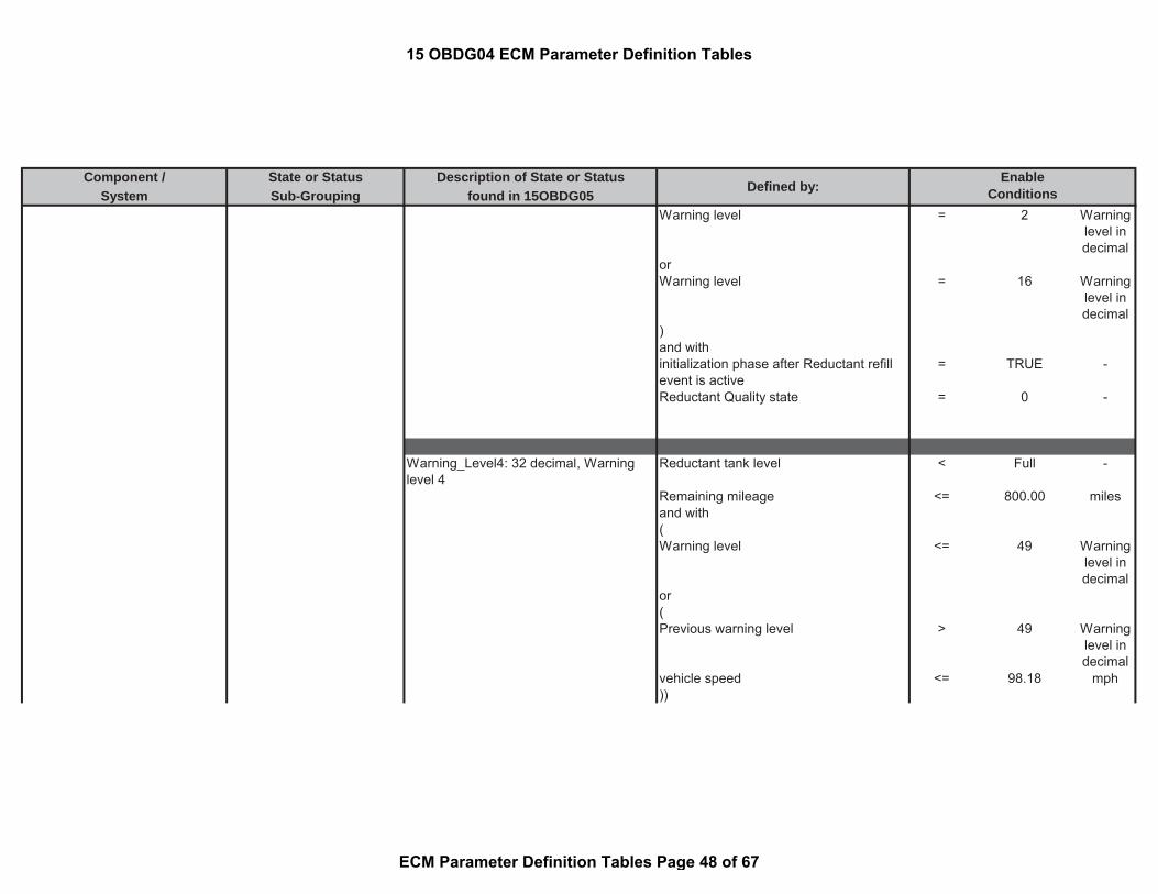
Component / State or Status Description of State or StatusSystem Sub-Grouping found in 15OBDG05
Defined by:Enable
ConditionsWarning level = 2 Warning
level indecimal
orWarning level = 16 Warning
level indecimal
)and withinitialization phase after Reductant refillevent is active
= TRUE -
Reductant Quality state = 0 -
Warning_Level4: 32 decimal, Warninglevel 4
Reductant tank level < Full -
Remaining mileage <= 800.00 milesand with(Warning level <= 49 Warning
level indecimal
or(Previous warning level > 49 Warning
level indecimal
vehicle speed <= 98.18 mph))
15 OBDG04 ECM Parameter Definition Tables
ECM Parameter Definition Tables Page 48 of 67

Component / State or Status Description of State or StatusSystem Sub-Grouping found in 15OBDG05
Defined by:Enable
Conditionsand withReductant Quality state = 0 -
Warning_Level5: 48 decimal, Warninglevel 5
((
Reductant tank level < Full -Remaining mileage <= 575.00 milesand with(Warning level <= 49 Warning
level indecimal
or(Previous warning level > 49 Warning
level indecimal
vehicle speed <= 98.18 mph)))or(Warning level = 48 Warning
level indecimal
initialization phase after Reductant refillevent is active
= TRUE -
))
15 OBDG04 ECM Parameter Definition Tables
ECM Parameter Definition Tables Page 49 of 67

Component / State or Status Description of State or StatusSystem Sub-Grouping found in 15OBDG05
Defined by:Enable
Conditionsand withReductant Quality state = 0 -
Warning_Level6: 49 decimal, Warninglevel 6
((
Warning level = 49 Warninglevel indecimal
initialization phase after Reductant refillevent is active
= TRUE -
)or(Warning level < 49 Warning
level indecimal
Failed Reductant system pressure buildup
= 1 -
))and withReductant Quality state = 0 -
Warning_Level8: 80 decimal,Vehiclespeed restriction mild
Warning level = 80 Warninglevel indecimal
15 OBDG04 ECM Parameter Definition Tables
ECM Parameter Definition Tables Page 50 of 67

Component / State or Status Description of State or StatusSystem Sub-Grouping found in 15OBDG05
Defined by:Enable
Conditionsinitialization phase after Reductant refillevent is active
= TRUE -
and withReductant Quality state = 0 -
Warning_Level10: 112 decimal,Vehiclespeed restriction aggressive
Warning level = 112 Warninglevel indecimal
initialization phase after Reductant refillevent is active
= TRUE -
and withReductant Quality state = 0 -
Warning_Level12: 144 decimal, Vehiclespeed restriction severe
Warning level = 144 Warninglevel indecimal
initialization phase after Reductant refillevent is active
= TRUE -
and withReductant Quality state = 0 -
Warning_Level14: 176 decimal, Vehiclespeed restriction final
Warning level = 176 Warninglevel indecimal
15 OBDG04 ECM Parameter Definition Tables
ECM Parameter Definition Tables Page 51 of 67

Component / State or Status Description of State or StatusSystem Sub-Grouping found in 15OBDG05
Defined by:Enable
Conditionsinitialization phase after Reductant refillevent is active
= TRUE -
and withReductant Quality state = 0 -
Reductant frozen SystemStates
Frozen state is active during a certainwarning level
ignition = On
for time > 5.00 secReductant tank Temperature <= -9.04 °CReductant low warning level (Please seethe definition)
>= 96.00 level
Status of Reductant tank as frozen(Engine off Time > 14400.00 secReductant tank Temperature < -11.04 °C)or(Engine off Time <= 7200.00 sectime since the following conditions aremet
<= 7200.00 sec
(status of reductant tank heater defrost = On or Defrost -Vehicle speed > 6.22 mph
15 OBDG04 ECM Parameter Definition Tables
ECM Parameter Definition Tables Page 52 of 67

Component / State or Status Description of State or StatusSystem Sub-Grouping found in 15OBDG05
Defined by:Enable
ConditionsStatus of urea tank as frozen (please seethe definition)
= TRUE -
))
SCR System Pressure State Status of Low Reductant Pump Pressure -Under Reductant warning level 3 - Mainstate 0x30
Reductant low warning level (Please seethe definition)
>= 64.00 -
number of pressure build-up attempts >= 2.00 countsand(status of SCR control sub state (pleasesee the definition)
= Pressure Buildup
-
Reductant Pump Module Pressure < 375.00 kPaDwell time in Pressure Build up substate > 15.00 sec
system pressurizes in pressure buildupand ventilation states
>= 10.00 counts
Reductant Defrost check (please see thedefinition)
= TRUE -
)
SCR System Diagnosis SCR System Long TermAdaptation Release States
Long-term Adaption Triggered
underdosing detected (please see thedefinition)
= TRUE -
15 OBDG04 ECM Parameter Definition Tables
ECM Parameter Definition Tables Page 53 of 67

Component / State or Status Description of State or StatusSystem Sub-Grouping found in 15OBDG05
Defined by:Enable
ConditionsORoverdosing detected (please see thedefinition)
= TRUE -
Underdosing detectedDifference between the NOx mass of thesensor and of the model during firstfunctional evaluation (see Look-Up-Table#13)
>= 0.4 to 0.45 g
ORDifference between the NOx mass of thesensor and of the model during secondfunctional evaluation (see Look-Up-Table#14)
>= 0.08 to 0.09 g
ORDifference between the NOx mass of thesensor and of the model during thirdfunctional evaluation (see Look-Up-Table#15)
>= -0.1 to -0.07 g
Overdosing detectedDifference between the NOx mass of thesensor and of the model during firstfunctional evaluation (see Look-Up-Table#10)
<= -0.55 to -0.38 g
OR
15 OBDG04 ECM Parameter Definition Tables
ECM Parameter Definition Tables Page 54 of 67

Component / State or Status Description of State or StatusSystem Sub-Grouping found in 15OBDG05
Defined by:Enable
ConditionsDifference between the NOx mass of thesensor and of the model during secondfunctional evaluation (see Look-Up-Table#11)
<= -0.39 to -0.3 g
ORDifference between the NOx mass of thesensor and of the model during thirdfunctional evaluation (see Look-Up-Table#12)
<= -0.27 to -0.2 g
Status of the SCR adaptation plausibilitycheck active
(
Status of NOx signal of downstream NOxsensor (please see the definition)
= True
NOx concentration downstream SCRcatalyst
> 15.00 ppm
for time > 0.50 sec
Estimated SCR catalyst efficiency > 0.70 factorfor time > 1.00 sec
NOx concentration deviation betweensensor reading and modeled NOxconcentration downstream SCR catalyst
> measuredparameter
-
for time > 0.50 sec
15 OBDG04 ECM Parameter Definition Tables
ECM Parameter Definition Tables Page 55 of 67

Component / State or Status Description of State or StatusSystem Sub-Grouping found in 15OBDG05
Defined by:Enable
Conditions(Time since when the Reductant loadlevel adaptation and the plausibility havebeen locked
>= 240.00 sec
orTime since when the Reductant loadlevel adaptation and the plausibility havebeen locked
>= 120.00 sec
Integrated NOx mass since Reductantload level adaptation and plausibility havebeen locked
>= 1.20 g
)
Difference between nominal andestimated Reductant
< 0.10 g
Difference between nominal andestimated Reductant
>= -1.00 g
Filtered Upstream NOx mass flow >= 0.00 g/secFiltered Upstream NOx mass flow <= 0.05 g/sec(Upstream NOx mass flow difference : (a) -(b)
>= -0.05 g/sec
Upstream NOx mass flow difference : (a) -(b)
<= 0.04 g/sec
and with(a) Filtered Upstream NOx mass flow(b) Filtered actual upstream NOx massflow
)
15 OBDG04 ECM Parameter Definition Tables
ECM Parameter Definition Tables Page 56 of 67

Component / State or Status Description of State or StatusSystem Sub-Grouping found in 15OBDG05
Defined by:Enable
ConditionsStatus of pre controlled dosing (pleasesee the definition)
= False
Difference between nominal andestimated Reductant
< 0.05 g
Difference between nominal andestimated Reductant
>= -1.00 g
for time > 0.20 sec
HC load in SCR catalyst <= 1.20 factoroverall aging factor of the SCR catalyst >= 0.00 factor
for time > 10.00 sec
Temperature gradient of SCR >= -327.68 °C/secTemperature gradient of SCR <= 327.67 °C/sec
for time > 0.20 sec
Integrated NOx mass flow after enginestart
>= 0.00 g
Release of Reductant dosing = active
engine operating condition based onengine speed and injection quantity
> 0 factor
(Difference between nominal andestimated Reductant
> -0.05 g
Reductant mass flow (see Look-Up-Table#9)
> 0 to 0.04 g
Elapsed time of the fill level timer > 20.00 sec)
15 OBDG04 ECM Parameter Definition Tables
ECM Parameter Definition Tables Page 57 of 67

Component / State or Status Description of State or StatusSystem Sub-Grouping found in 15OBDG05
Defined by:Enable
Conditions
State of the NH3 (Ammonia) slipdetection
Reductant concentration downstreamSCR
< 30.00 ppm
and(a) - (b) < 0.00 g/sec
(a) Filtered NOx mass flow downstreamSCR measured by the sensor
= measuredparameter
-
(b) Filtered and delayed NOx rawemission mass flow upstream of SCR
= measuredparameter
-
Deactivation of dosing to execute theNOx Offset test
SCR catalyst temperature > 49.96 °CSCR catalyst temperature < 349.96 °Ctime > 60.00 sec
andCurrently dosed Reductant mass flow <= 0.05 g/sectime > 300.00 sec
andFeed ratio(a ) / (( b) * ( c)) <= 0.10 ratio
15 OBDG04 ECM Parameter Definition Tables
ECM Parameter Definition Tables Page 58 of 67

Component / State or Status Description of State or StatusSystem Sub-Grouping found in 15OBDG05
Defined by:Enable
Conditions(a) Currently dosed Reductant massflow
= measuredparameter
-
(b) NOx raw emission mass flow = measuredparameter
-
( c) Stoichiometric conversion factorNOx to Reductant
= calculatedparameter
-
for time > 300.00 sec
andEstimated current Reductant load <= 1.30 gtime > 30.00 sec
Release plausibility of Reductant LoadRelease plausibility timer active >= 240.00 secor(Release plausibility timer active >= 120.00 secIntegrated NOx raw emission since filllevel adaptation and plausibility havebeen locked
>= 1.20 g
)
Status for disabling the SCR Efficiencymonitor following an SCR Adaptationcycle completion
Maximum dosing quantity < 0.60 g/sec
15 OBDG04 ECM Parameter Definition Tables
ECM Parameter Definition Tables Page 59 of 67

Component / State or Status Description of State or StatusSystem Sub-Grouping found in 15OBDG05
Defined by:Enable
Conditions
or(a) - (b) > 0
(a) Reductant Dosing quantity = measuredparameter
-
(b) Maximum Reductant Dosingquantity
= calculatedparameter
-
or(a) - (b) > 0
(a) Reductant Desired value = calculatedparameter
-
(b) Reductant Dosing quantity limitationdue to frozen tank
= calculatedparameter
-
Request for pre controlled dosing
Filtered exhaust gas mass flow > (a) * (b) -(a) Correction factor for the upperhysteresis threshold for filtered exhaust-gas mass flow, dependent on HC-contamination
= 1 factor
(b) Upper hysteresis threshold forfiltered exhaust-gas mass flow,dependent on thermal ageing
= 910.17 g/sec
and
15 OBDG04 ECM Parameter Definition Tables
ECM Parameter Definition Tables Page 60 of 67

Component / State or Status Description of State or StatusSystem Sub-Grouping found in 15OBDG05
Defined by:Enable
ConditionsFiltered NOx mass flow upstream SCR > (a) * (b) -
(a) Correction factor for the upperhysteresis threshold for filtered exhaust-gas mass flow, dependent on HC-contamination SCR
= 1 factor
(b) Upper hysteresis threshold forfiltered exhaust-gas mass flow,dependent on thermal ageing SCR
= 0.02 g/sec
andEngine coolant temperature < (a) + (b)
(a) Lower hysteresis threshold forengine temperature
= 2999.96 °C
(b) Offset for lower hysteresis switch onthreshold for engine temperature
= 0.00 °C
Engine coolant temperature > 3003.56 °C
andambient pressure > (a) + (b)
(a) Upper hysteresis threshold forenvironment pressure
= 74.00 kPa
(b) Offset for upper hysteresis switch onthreshold for environment pressure
= 27.00 kPa
orambient pressure < 73.50 kPa
andIntake air temperature > (a) + (b)
(a) Lower hysteresis switch onthreshold for inlet air temperature
= -10.04 °C
15 OBDG04 ECM Parameter Definition Tables
ECM Parameter Definition Tables Page 61 of 67

Component / State or Status Description of State or StatusSystem Sub-Grouping found in 15OBDG05
Defined by:Enable
Conditions(b) Offset for upper hysteresis switch onthreshold for inlet air temperature
= 403.00 °C
orIntake air temperature < -50.04 °C
)
and(ambient temperature >= -9.04 °Cambient pressure >= 74.80 kPaSelected temperature used for lockingpre controlled mode
>= -3549.94 °C
Selected temperature used for lockingpre controlled mode
<= 369.96 °C
engine operation in normal mode = TRUE -
SCR NOx Catalyst Efficiency check wasperformed this drive cycle
= FALSE -
Incorrect Reductant Composition checkwas performed this drive cycle
= FALSE -
NO Pending or Confirmed DTCs: = TRUE -)
(((k) + (l) + ( m) > 0.00
(k) = (a) * (b)
15 OBDG04 ECM Parameter Definition Tables
ECM Parameter Definition Tables Page 62 of 67

Component / State or Status Description of State or StatusSystem Sub-Grouping found in 15OBDG05
Defined by:Enable
Conditions(a) entry condition for pre controlleddosing at sea level
= 0 -
(b) Altitude multiplier factor for sea level = measuredparameter
-
(l) = ( c) * (d) * (e)( c) entry condition for online dosing atMid level
= 0 -
(d) Multiplier to Mid Level enable speedload map
= 1 factor
(e) Altitude multiplier factor for mediumaltitude
= measuredparameter
-
(m) = ( f) * (g) * (h)(f) Entry condition for online dosing atHi level
= 0 -
(g) Multiplier to Hi Level enable speedload map
= 1 factor
(h) Altitude multiplier factor for highaltitude
= measuredparameter
-
)andLow pass filtered upstream NOx sensorsignal
> 0 ppm
)
15 OBDG04 ECM Parameter Definition Tables
ECM Parameter Definition Tables Page 63 of 67

Component / State or Status Description of State or StatusSystem Sub-Grouping found in 15OBDG05
Defined by:Enable
ConditionsReductant Tank HeaterPerformance DiagnosisStatus
start temperature is captured in EERPOMif monitoring is active over several drivingcycles
continuation of previously started tanktemperature performance monitoringcycle (see definition)
= 1.56 °C
or(
start temperature is captured in EERPOMif monitoring is not active over severaldriving cycles
continuation of previously started tanktemperature performance monitoringcycle (see definition)
= FALSE -
(ignition on for time > 60.00 secor = TRUEice detection by tank temperaturedifference:
(a) - (b) <= -0.54 °C(a) filtered current tank temperature = measured
parameter-
(b) tank temperature captured at thebeginning of current monitoring cycle
= measuredparameter
-
))or(a) - (b) <= -0.54 °C
(a) filtered current tank temperature = measuredparameter
-
(b) tank temperature captured at thebeginning of current monitoring cycle
= measuredparameter
-
ormonitoring was performed in previousdriving cycle
= TRUE -
15 OBDG04 ECM Parameter Definition Tables
ECM Parameter Definition Tables Page 64 of 67

Component / State or Status Description of State or StatusSystem Sub-Grouping found in 15OBDG05
Defined by:Enable
Conditions
continuation of previously started tanktemperature performance monitoringcycle
temperature difference: (a) - (b) <= 1.56 °C
(a) filtered current tank temperature = measuredparameter
-
(b) tank temperature of the previousdriving cycle
= measuredparameter
-
temperature difference: (a) - (b) <= 0 °C(a) tank temperature of the previousdriving cycle
= measuredparameter
-
(b) filtered current tank temperature = measuredparameter
-
temperature difference: (a) - (b) >= 0 °C(a) tank temperature of the previousdriving cycle
= measuredparameter
-
(b) start tank temperature of currentmonitoring cycle from EEPROM (seedefinition)
= measuredparameter
-
Engine off Time <= 2000.00 secThis monitor was complete in the lastdriving cycle
= FALSE
ice detection by tank temperaturedifference:(a) - (b) > -0.54 °C
(a) filtered current tank temperature = measuredparameter
-
15 OBDG04 ECM Parameter Definition Tables
ECM Parameter Definition Tables Page 65 of 67
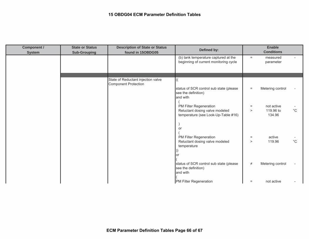
Component / State or Status Description of State or StatusSystem Sub-Grouping found in 15OBDG05
Defined by:Enable
Conditions(b) tank temperature captured at thebeginning of current monitoring cycle
= measuredparameter
-
State of Reductant injection valveComponent Protection
((
status of SCR control sub state (pleasesee the definition)
= Metering control -
and with(PM Filter Regeneration = not active -Reluctant dosing valve modeledtemperature (see Look-Up-Table #16)
> 119.96 to134.96
°C
)or(PM Filter Regeneration = active -Reluctant dosing valve modeledtemperature
> 119.96 °C
))or(status of SCR control sub state (pleasesee the definition)
≠ Metering control -
and with(PM Filter Regeneration = not active -
15 OBDG04 ECM Parameter Definition Tables
ECM Parameter Definition Tables Page 66 of 67

Component / State or Status Description of State or StatusSystem Sub-Grouping found in 15OBDG05
Defined by:Enable
ConditionsModeled Reductant injection valve tiptemperature based on its coiltemperature (see Look-Up-Table #16)
> 119.96 to134.96
°C
)or(PM Filter Regeneration = active -Modeled Reductant injection valve tiptemperature based on its coiltemperature
> 119.96 °C
)))
Turbo Charger Turbocharger (VNT) wiping active The Variable Nozzle TurbochargerControl has an intrusive mode where:VNT wiping is a sweep of the vaneposition control throughout its range ofmotion which is used to:avoid a binding of the VNT vanes due tosoot accumulation during long idleoperation with a cold engine.
15 OBDG04 ECM Parameter Definition Tables
ECM Parameter Definition Tables Page 67 of 67

Table no. Fault Codes Label (Internal Manufacturer Reference)
1 P0101 AFS_rAirThresLo_MAP
Injection Qty (mm^3/rev) / Ambient Pressure (kPa) 0 95 110 180 250 300 400 5002 0.85 0.85 0.85 0.85 0.8 0.8 0.8 0.84 0.85 0.85 0.85 0.85 0.8 0.8 0.8 0.8
70 0.85 0.85 0.85 0.85 0.8 0.8 0.8 0.880 0.8 0.8 0.8 0.8 0.8 0.8 0.8 0.8
100 0.8 0.8 0.8 0.8 0.8 0.8 0.8 0.8120 0.8 0.8 0.8 0.8 0.8 0.8 0.8 0.8140 0.8 0.8 0.8 0.8 0.8 0.8 0.8 0.8200 0.8 0.8 0.8 0.8 0.8 0.8 0.8 0.8
2 P2199 Air_tDiffMaxHiTAFS_CUR
Engine Off Time (sec) 600 700 800 900 1000 2000 3000 4000 5000 8000 17999 18000 28799 28800 30000 32000Delta Temperature (°C) 999 999 999 999 999 999 999 999 999 999 999 999 999 20 20 20
3 P10CF Air_tDiffMaxHiTCACDs_CUR
Engine Off Time (sec) 600 700 800 900 1000 2000 3000 4000 5000 8000 17999 18000 28799 28800 30000 32000Delta Temperature (°C) 999 999 999 999 999 999 999 999 999 999 999 999 999 25 25 25
4 P040F Air_tDiffMaxHiTEGRClr2Ds_CUR
Engine Off Time (sec) 600 700 800 900 1000 2000 3000 4000 5000 8000 10000 15000 20000 25000 28800 30000Delta Temperature (°C) 3276.7 3276.7 3276.7 3276.7 3276.7 3276.7 3276.7 3276.7 3276.7 3276.7 3276.7 3276.7 3276.7 3276.7 20 20
8 P0401 AirCtl_facEnvPresMinDvt_CUR
Ambient Pressure (kPa) 70 77 80 85 90 95 100 110Correction Factor (factor) 0.6 0.6 0.625 0.7 0.8 1 1 1
9 P0401 AirCtl_mEGRMinDvtLim_CUR
Ambient Pressure (kPa) 67 75 76 77 80 82 85 88 91 95 98 101EGR Commanded Air Mass (g/rev) 0.34 0.34 0.34 0.34 0.34 0.34 0.344 0.368 0.384 0.406 0.424 0.44
15 OBDG04 ECM Calibration Look-Up Tables
ECM Calibration Look-Up Tables Page 1 of 22

Table no. Fault Codes Label (Internal Manufacturer Reference)
10 P0402 AirCtl_mMaxDvt_MAP
Injection Qty (mm^3/rev) / Engine Speed (rpm) 1000 1200 1400 1500 1600 1800 2000 220010 0.033 0.033 0.033 0.033 0.033 0.033 0.033 0.03320 0.033 0.033 0.033 0.033 0.033 0.033 0.033 0.03330 0.033 0.033 0.050 0.033 0.033 0.033 0.033 0.03340 0.033 0.033 0.050 0.033 0.033 0.033 0.033 0.03360 0.033 0.033 0.045 0.033 0.040 0.060 0.075 0.07580 0.035 0.035 0.035 0.035 0.040 0.060 0.075 0.07590 0.040 0.040 0.040 0.040 0.040 0.060 0.075 0.075
100 0.060 0.060 0.060 0.060 0.060 0.060 0.075 0.075
11 P0401 AirCtl_mMinDvt_MAP
Injection Qty (mm^3/rev) / Engine Speed (rpm) 1000 1300 1400 1500 1600 1800 1900 20002 -0.040 -0.050 -0.050 -0.050 -0.050 -0.050 -0.075 -0.1506 -0.040 -0.050 -0.050 -0.050 -0.050 -0.050 -0.075 -0.150
10 -0.040 -0.050 -0.050 -0.050 -0.050 -0.050 -0.075 -0.15015 -0.040 -0.050 -0.050 -0.050 -0.050 -0.050 -0.075 -0.15020 -0.040 -0.048 -0.050 -0.050 -0.050 -0.075 -0.075 -0.15025 -0.040 -0.040 -0.053 -0.053 -0.053 -0.075 -0.075 -0.15030 -0.040 -0.040 -0.075 -0.075 -0.075 -0.075 -0.075 -0.15040 -0.040 -0.040 -0.150 -0.150 -0.150 -0.150 -0.150 -0.150
12 P2138 APP_uSync_CUR
Accel Pedal Voltage (V) 0.500 2.100 2.100Pedal Deviation (V) 0.120 0.180 0.180
13 P057B Brk_facEWMASlowTest_CUR
Brake Position Sensor Voltage (V) 0 0.0346 0.035 0.04 0.045 0.051 0.0512 5factor (-) 0 0 0 0 0 0 1 1
14 P026A CAClg_dmThresHi_CUR
15 OBDG04 ECM Calibration Look-Up Tables
ECM Calibration Look-Up Tables Page 2 of 22

Table no. Fault Codes Label (Internal Manufacturer Reference)
Vehicle Speed (mph) 24.85 74.56Air Mass Flow (g/sec) 55.556 277.78
15 P011B CEngDsT_tDiffMaxHi_CUR
Engine Off Time (sec) 600 700 800 900 1000 2000 3000 4000 5000 8000 17999 18000 28799 28800 30000 32767Delta Temperature (°C) 999 999 999 999 999 999 999 999 999 999 999 999 999 20 20 20
17 P0336 EpmCrS_facGapPlausHigh_CA
- 8 5.81 3.38 3.38
18 P0336 EpmCrS_facIncPlausHigh_CA
- 2 1.81 1.5 1.5
19 P02CD, P02CF, P02D1, P02D3 ETClb_pRailSet_CA
Rail Pressure Setpoint (kPa) 0 30000 80000
20 P02CD, P02CF, P02D1, P02D3 ETClb_tiET_MAX_CA
Injector Energizing Time (μsec) 0 547.2 304.4
21 P02CD, P02CF, P02D1, P02D3 ETClb_tiET_MIN_CA
Injector Energizing Time (μsec) 0 137.2 107.2
15 OBDG04 ECM Calibration Look-Up Tables
ECM Calibration Look-Up Tables Page 3 of 22
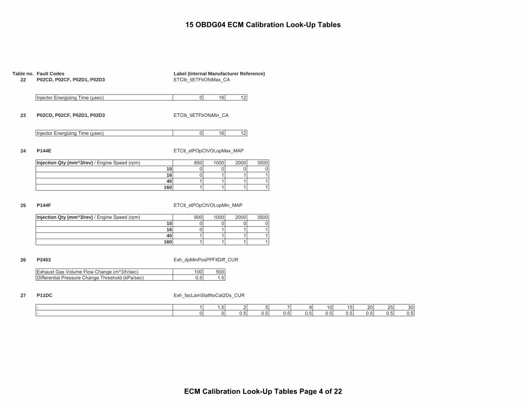
Table no. Fault Codes Label (Internal Manufacturer Reference)22 P02CD, P02CF, P02D1, P02D3 ETClb_tiETFbOfsMax_CA
Injector Energizing Time (μsec) 0 16 12
23 P02CD, P02CF, P02D1, P02D3 ETClb_tiETFbOfsMin_CA
Injector Energizing Time (μsec) 0 16 12
24 P144E ETCtl_stPOpCtVOLopMax_MAP
Injection Qty (mm^3/rev) / Engine Speed (rpm) 850 1000 2000 350010 0 0 0 016 0 1 1 140 1 1 1 1
160 1 1 1 1
25 P144F ETCtl_stPOpCtVOLopMin_MAP
Injection Qty (mm^3/rev) / Engine Speed (rpm) 900 1000 2000 350010 0 0 0 016 0 1 1 140 1 1 1 1
160 1 1 1 1
26 P2453 Exh_dpMinPosPPFltDiff_CUR
Exhaust Gas Volume Flow Change (m^3/h/sec) 100 500Differential Pressure Change Threshold (kPa/sec) 0.5 1.5
27 P11DC Exh_facLamStatNoCat2Ds_CUR
- 1 1.5 2 5 7 9 10 15 20 25 30- 0 0 0.5 0.5 0.5 0.5 0.5 0.5 0.5 0.5 0.5
15 OBDG04 ECM Calibration Look-Up Tables
ECM Calibration Look-Up Tables Page 4 of 22

Table no. Fault Codes Label (Internal Manufacturer Reference)
28 P11DB Exh_facLamStatNSCDs_CUR
- 1 1.5 2 5 7 9 10 15 20 25 30- 0 0 0.5 0.5 0.5 0.5 0.5 0.5 0.5 0.5 0.5
30 P11D3, P11D4 Exh_mAirAdapActvNSCDs_CUR
Upstream Measure NOx at DFCO Start (ppm) 0 20 50 100 200 300 400 500 600 700 800 900 1000 1200 1400 1600Integrated Air Mass Flow (g) 100 100 125 150 250 300 300 350 350 400 400 500 500 500 500 500
31 P20E2 Exh_tDiffMaxHiTOxiCatDs_CUR
Engine Off Time (sec) 600 700 800 900 1000 2000 3000 4000 5000 8000 10000 15000 20000 25000 28800 32000Delta Temperature (°C) 3276.7 3276.7 3276.7 3276.7 3276.7 3276.7 3276.7 3276.7 3276.7 3276.7 3276.7 3276.7 3276.7 3276.7 20 20
32 P20E4 Exh_tDiffMaxHiTPFltDs_CUR
Engine Off Time (sec) 600 700 800 900 1000 2000 3000 4000 5000 8000 10000 15000 20000 25000 28800 32000Delta Temperature (°C) 3276.7 3276.7 3276.7 3276.7 3276.7 3276.7 3276.7 3276.7 3276.7 3276.7 3276.7 3276.7 3276.7 3276.7 20 20
33 P24B 7 -
PM Sensor Temperature (°C) -30.00 19.98 69.98 119.98 150.00Heater Resistance (Ohm) 2.93 3.26 3.60 3.93 4.13
34 P24B 7 -
PM Sensor Temperature (°C) -30.00 19.98 69.98 119.98 150.00Heater Resistance (Ohm) 1.09 1.29 1.49 1.69 1.81
35 P2598, P2599 TrbCh_tiEnaMonDlyBrk_CUR
Ambient Pressure (kPa) 50.00 59.80 59.90 60.00 65.00 70 76 84 96 100Delay Time (sec) 15.00 15.00 15.00 15.00 15.00 10 10 5 5 5
15 OBDG04 ECM Calibration Look-Up Tables
ECM Calibration Look-Up Tables Page 5 of 22

Table no. Fault Codes Label (Internal Manufacturer Reference)
37 P0263, P0266, P0269, P0272 FBC_qLimNeg_MAP
ECT (°C) / Inj. Qty (mm^3/rev) 0 4 28 200 202 204 206 208-40.04 0 0 -24 -24 -24 -24 -24 -24-15.04 0 0 -24 -24 -24 -24 -24 -24
9.96 0 0 -24 -24 -24 -24 -24 -2434.96 0 0 -24 -24 -24 -24 -24 -2459.96 0 0 -24 -24 -24 -24 -24 -2484.96 0 0 -24 -24 -24 -24 -24 -24
109.96 0 0 -24 -24 -24 -24 -24 -24134.96 0 0 -24 -24 -24 -24 -24 -24
38 P0263, P0266, P0269, P0272 FBC_qLimPos_MAP
ECT (°C) / Inj. Qty (mm^3/rev) 0 4 28 200 202 204 206 208-40.04 0 0 24 24 24 24 24 24-15.04 0 0 24 24 24 24 24 24
9.96 0 0 24 24 24 24 24 2434.96 0 0 24 24 24 24 24 2459.96 0 0 24 24 24 24 24 2484.96 0 0 24 24 24 24 24 24
109.96 0 0 24 24 24 24 24 24134.96 0 0 24 24 24 24 24 24
39 P026D FMO_qFlSysThresMax_MAP
Injection Qty (mm^3/rev) / Air Mass per Cylinder (g/rev) 0.135 0.15 0.175 0.2 0.225 0.25 0.275 0.312 0.2 0.2 0.2 0.2 0.2 0.2 0.2 0.214 0.6 0.6 0.6 0.6 0.6 0.6 0.6 0.616 1 1 1 1 1 1 1 118 1.8 1.8 1.8 1.8 1.8 1.8 1.8 1.820 2.4 2.4 2.4 2.4 2.4 2.4 2.4 2.422 3.4 3.4 3.4 3.4 3.4 3.4 3.4 3.424 4.4 4.4 4.4 4.4 4.4 4.4 4.4 4.426 5.4 5.4 5.4 5.4 5.4 5.4 5.4 5.4
15 OBDG04 ECM Calibration Look-Up Tables
ECM Calibration Look-Up Tables Page 6 of 22

Table no. Fault Codes Label (Internal Manufacturer Reference)
40 P026C, P026D FMO_stOutObsvr_MAP
Injection Qty (mm^3/rev) / Engine Speed (rpm) 500 1000 1500 2000 2500 3000 3500 4000 4500 50004 0 0 0 0 0 0 0 0 0 0
12 1 1 1 1 1 1 1 1 1 124 1 1 1 1 1 1 1 1 1 136 1 1 1 1 1 1 1 1 1 148 1 1 1 1 1 1 1 1 1 160 1 1 1 1 1 1 1 1 1 172 1 1 1 1 1 1 1 1 1 184 1 1 1 1 1 1 1 1 1 1
100 1 1 1 1 1 1 1 1 1 1120 1 1 1 1 1 1 1 1 1 1
41 P054F InjCtl_qDesGearMonMax_MAP
ECT (°C) / Engine Speed (rpm) 0 400 600 825 1050 5000-20.04 176.8 176.8 176.8 176.8 176.8 176.8-10.04 133.8 133.8 133.8 133.8 133.8 133.8
-0.04 132.4 132.4 132.4 132.4 132.4 132.419.96 106.2 106.2 106.2 106.2 106.2 106.239.96 85.8 85.8 85.8 85.8 85.8 85.869.96 81.2 81.2 81.2 81.2 81.2 81.2
42 P054F InjCtl_qDesNeutrGearMonMax_MAP
ECT (°C) / Engine Speed (rpm) 0 400 600 825 1050 5000-20.04 111.8 111.8 111.8 111.8 111.8 111.8
-0.04 93.4 93.4 93.4 93.4 93.4 93.49.96 79.2 79.2 79.2 79.2 79.2 79.2
39.96 70.6 70.6 70.6 70.6 70.6 70.669.96 66 66 66 66 66 6684.96 60.2 60.2 60.2 60.2 60.2 60.2
43 P054E InjCtl_qDesNeutrGearMonMin_MAP
15 OBDG04 ECM Calibration Look-Up Tables
ECM Calibration Look-Up Tables Page 7 of 22
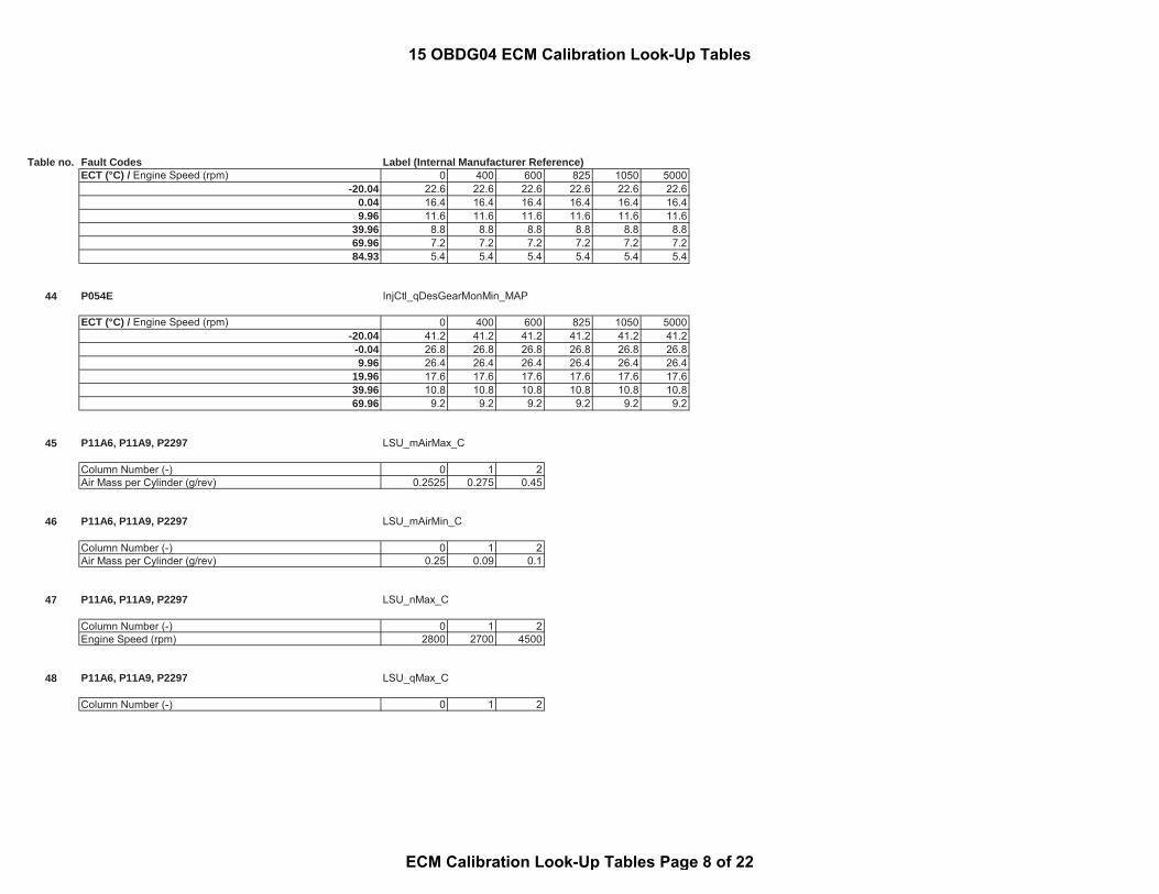
Table no. Fault Codes Label (Internal Manufacturer Reference)ECT (°C) / Engine Speed (rpm) 0 400 600 825 1050 5000
-20.04 22.6 22.6 22.6 22.6 22.6 22.60.04 16.4 16.4 16.4 16.4 16.4 16.49.96 11.6 11.6 11.6 11.6 11.6 11.6
39.96 8.8 8.8 8.8 8.8 8.8 8.869.96 7.2 7.2 7.2 7.2 7.2 7.284.93 5.4 5.4 5.4 5.4 5.4 5.4
44 P054E InjCtl_qDesGearMonMin_MAP
ECT (°C) / Engine Speed (rpm) 0 400 600 825 1050 5000-20.04 41.2 41.2 41.2 41.2 41.2 41.2
-0.04 26.8 26.8 26.8 26.8 26.8 26.89.96 26.4 26.4 26.4 26.4 26.4 26.4
19.96 17.6 17.6 17.6 17.6 17.6 17.639.96 10.8 10.8 10.8 10.8 10.8 10.869.96 9.2 9.2 9.2 9.2 9.2 9.2
45 P11A6, P11A9, P2297 LSU_mAirMax_C
Column Number (-) 0 1 2Air Mass per Cylinder (g/rev) 0.2525 0.275 0.45
46 P11A6, P11A9, P2297 LSU_mAirMin_C
Column Number (-) 0 1 2Air Mass per Cylinder (g/rev) 0.25 0.09 0.1
47 P11A6, P11A9, P2297 LSU_nMax_C
Column Number (-) 0 1 2Engine Speed (rpm) 2800 2700 4500
48 P11A6, P11A9, P2297 LSU_qMax_C
Column Number (-) 0 1 2
15 OBDG04 ECM Calibration Look-Up Tables
ECM Calibration Look-Up Tables Page 8 of 22

Table no. Fault Codes Label (Internal Manufacturer Reference)Injection Quantity (mm^3/rev) 44 36 0.4
49 P11A6, P11A9, P2297 LSU_qMin_C
Column Number (-) 0 1 2Injection Quantity (mm^3/rev) 16 8 -1
50 P11A9, P2297 LSU_rO2NegDvt_C
Column Number (-) 0 1 2Difference between Calculated and Mesaured O2 (-) 0.07 0.07 0.06
51 P11A6, P2297 LSU_rO2PosDvt_C
Column Number (-) 0 1 2Difference between Calculated and Mesaured O2 (-) 0.07 0.07 0.04
52 P0300, P0301, P0302, P0303, P0304 MisfDet_dnThresIdl_CUR
Injection Quantity (mm^3/rev) 8.64 26.1 45 75.24Crankshaft Angular Acceleration (s^(-2)) -2.5234 -3.9609 -5.0391 -5.7578
53 P0606 MoFInjQnt_tiZFCETMax_CUR
Rail Pressure (kPa) 30400 70400 80000 90400 120000 130400Energizing Time (μsec) 500 300 275.2 250 158 50
54 P0606 MoFInjQnt_tiZFCETMin_CUR
Rail Pressure (kPa) 30400 70400 80000 90400 120000 130400Energizing Time (μsec) -500 -300 -274.8 -250 -158 -50
55 P0606 MoFOvR_tiLimET_CUR
15 OBDG04 ECM Calibration Look-Up Tables
ECM Calibration Look-Up Tables Page 9 of 22

Table no. Fault Codes Label (Internal Manufacturer Reference)Engine Speed (rpm) 0 2080 2120 4000Energizing Time (μsec) 6000 6000 200 200
57 P0299 PCR_pMaxDvt_MAP
Injection Qty (mm^3/rev) / Engine Speed (rpm) 1000 1500 1750 2000 2500 3000 3500 400060 35 35 35 40 40 34 40 3570 35 35 37.5 40 50 50 40 3580 37 37 38 48 56 59 45 35
100 40 40 40 49 60 60 60 42120 45 45 45 55 60 60 60 50140 33 33 40 49 60 52.5 60 60160 46 46 46 54 57 60 60 60170 47 47 47 45 57 60 60 60
58 P0234 PCR_pMinDvt_MAP
Injection Qty (mm^3/rev) / Engine Speed (rpm) 2000 2200 2400 2600 2800 3000 3500 4000100 -25 -25 -25 -25 -25 -25 -25 -25110 -25 -25 -25 -25 -25 -25 -25 -25120 -25 -25 -25 -25 -25 -25 -25 -25130 -25 -25 -25 -25 -25 -25 -25 -25140 -25.5 -25.5 -25.5 -25.5 -25.5 -25.5 -25.5 -25.5150 -26 -26 -26 -26 -26 -26 -26 -26160 -27 -27 -27 -27 -27 -27 -27 -27170 -27 -27 -27 -27 -27 -27 -27 -27
59 P2263 PCR_pOvrBstDvt_MAP
Injection Qty (mm^3/rev) / Engine Speed (rpm) 1500 2000 2250 2500 2750 3000 3500 5500100 -40 -40 -40 -40 -40 -40 -40 -40110 -40 -40 -40 -40 -40 -40 -40 -40120 -40 -40 -42 -41 -40.5 -42 -44.5 -45130 -40 -40 -43 -42 -42 -42 -40.5 -40140 -40 -40 -44 -43 -43 -43 -43 -37150 -40 -40 -40.5 -44 -40 -40.5 -40 -34160 -40 -40 -38 -35 -35 -34 -31.5 -34
15 OBDG04 ECM Calibration Look-Up Tables
ECM Calibration Look-Up Tables Page 10 of 22
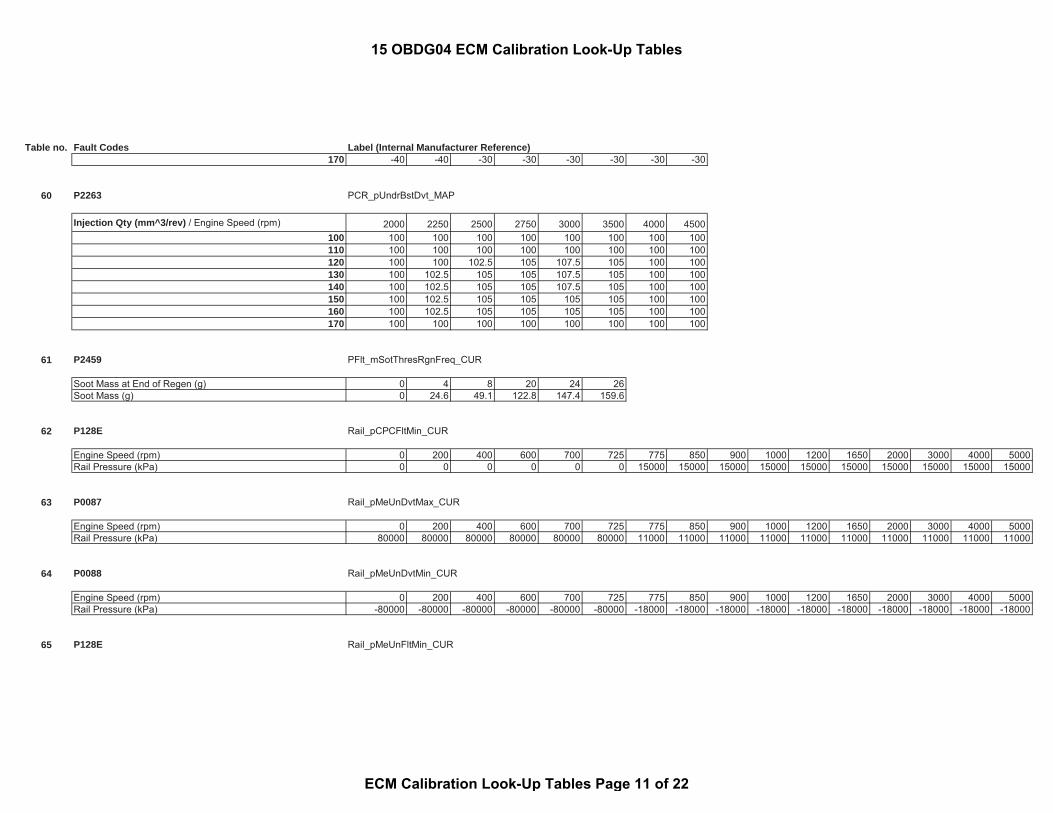
Table no. Fault Codes Label (Internal Manufacturer Reference)170 -40 -40 -30 -30 -30 -30 -30 -30
60 P2263 PCR_pUndrBstDvt_MAP
Injection Qty (mm^3/rev) / Engine Speed (rpm) 2000 2250 2500 2750 3000 3500 4000 4500100 100 100 100 100 100 100 100 100110 100 100 100 100 100 100 100 100120 100 100 102.5 105 107.5 105 100 100130 100 102.5 105 105 107.5 105 100 100140 100 102.5 105 105 107.5 105 100 100150 100 102.5 105 105 105 105 100 100160 100 102.5 105 105 105 105 100 100170 100 100 100 100 100 100 100 100
61 P2459 PFlt_mSotThresRgnFreq_CUR
Soot Mass at End of Regen (g) 0 4 8 20 24 26Soot Mass (g) 0 24.6 49.1 122.8 147.4 159.6
62 P128E Rail_pCPCFltMin_CUR
Engine Speed (rpm) 0 200 400 600 700 725 775 850 900 1000 1200 1650 2000 3000 4000 5000Rail Pressure (kPa) 0 0 0 0 0 0 15000 15000 15000 15000 15000 15000 15000 15000 15000 15000
63 P0087 Rail_pMeUnDvtMax_CUR
Engine Speed (rpm) 0 200 400 600 700 725 775 850 900 1000 1200 1650 2000 3000 4000 5000Rail Pressure (kPa) 80000 80000 80000 80000 80000 80000 11000 11000 11000 11000 11000 11000 11000 11000 11000 11000
64 P0088 Rail_pMeUnDvtMin_CUR
Engine Speed (rpm) 0 200 400 600 700 725 775 850 900 1000 1200 1650 2000 3000 4000 5000Rail Pressure (kPa) -80000 -80000 -80000 -80000 -80000 -80000 -18000 -18000 -18000 -18000 -18000 -18000 -18000 -18000 -18000 -18000
65 P128E Rail_pMeUnFltMin_CUR
15 OBDG04 ECM Calibration Look-Up Tables
ECM Calibration Look-Up Tables Page 11 of 22

Table no. Fault Codes Label (Internal Manufacturer Reference)
Engine Speed (rpm) 0 200 400 600 700 725 775 850 900 1000 1200 1650 2000 3000 4000 5000Rail Pressure (kPa) 0 0 0 0 0 0 15000 15000 15000 15000 15000 15000 15000 15000 15000 15000
66 P0087 Rail_pPCVDvtMax_CUR
Engine Speed (rpm) 0 200 400 600 700 725 775 850 900 1000 1200 1650 2000 3000 4000 5000Rail Pressure (kPa) 80000 80000 80000 80000 80000 80000 11000 11000 11000 11000 11000 11000 11000 11000 11000 11000
67 P128E Rail_pPCVFltMin_CUR
Engine Speed (rpm) 0 200 400 600 700 725 775 850 900 1000 1200 1650 2000 3000 4000 5000Rail Pressure (kPa) 0 0 0 0 0 0 15000 15000 15000 15000 15000 15000 15000 15000 15000 15000
68 P20EE SCRChk_facEtaEstOfs1_MAP
Filtered Exh Mass Flow (g/s) / SCR Upstream Temp (°C) 149.96 199.96 229.96 249.96 269.96 289.96 309.96 359.9611.11 -0.187 -0.187 -0.187 -0.161 -0.2 -0.206 -0.206 -0.20616.67 -0.187 -0.187 -0.187 -0.161 -0.22 -0.206 -0.206 -0.20622.22 -0.198 -0.198 -0.198 -0.171 -0.24 -0.206 -0.206 -0.20627.78 -0.235 -0.235 -0.235 -0.22 -0.24 -0.195 -0.188 -0.18833.33 -0.273 -0.273 -0.273 -0.23 -0.225 -0.185 -0.178 -0.17841.67 -0.294 -0.294 -0.294 -0.25 -0.22 -0.175 -0.172 -0.17250.00 -0.294 -0.294 -0.294 -0.26 -0.22 -0.173 -0.17 -0.1769.45 -0.294 -0.294 -0.294 -0.26 -0.22 -0.172 -0.17 -0.17
69 P11CC SCRChk_facRatHumMinNOxUs_CUR
Relative Humidity (%) 0 30.0049 40.0024 50 59.9976 75 90.002 100Correction Factor (factor) 1 1 1 1 1 1 1 1
70 P11CB, P11CC SCRChk_idcPOpMinNOxUsPlaus_GMAP
Injection Qty (mm^3/rev) / Engine Speed (rpm) 600 800 1000 1320 1400 1600 1800 2000 2200 2600 2800 3000 3200 4000 5000 1000010 0 0 0 0 0 0 0 0 0 0 0 0 0 0 0 014 0 0 0 0 0 0 0 0 0 0 0 0 0 0 0 0
15 OBDG04 ECM Calibration Look-Up Tables
ECM Calibration Look-Up Tables Page 12 of 22
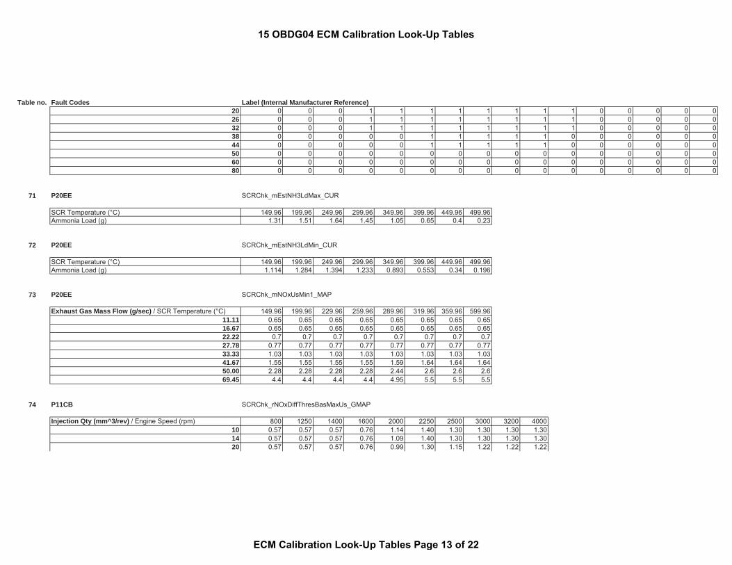
Table no. Fault Codes Label (Internal Manufacturer Reference)20 0 0 0 1 1 1 1 1 1 1 1 0 0 0 0 026 0 0 0 1 1 1 1 1 1 1 1 0 0 0 0 032 0 0 0 1 1 1 1 1 1 1 1 0 0 0 0 038 0 0 0 0 0 1 1 1 1 1 0 0 0 0 0 044 0 0 0 0 0 1 1 1 1 1 0 0 0 0 0 050 0 0 0 0 0 0 0 0 0 0 0 0 0 0 0 060 0 0 0 0 0 0 0 0 0 0 0 0 0 0 0 080 0 0 0 0 0 0 0 0 0 0 0 0 0 0 0 0
71 P20EE SCRChk_mEstNH3LdMax_CUR
SCR Temperature (°C) 149.96 199.96 249.96 299.96 349.96 399.96 449.96 499.96Ammonia Load (g) 1.31 1.51 1.64 1.45 1.05 0.65 0.4 0.23
72 P20EE SCRChk_mEstNH3LdMin_CUR
SCR Temperature (°C) 149.96 199.96 249.96 299.96 349.96 399.96 449.96 499.96Ammonia Load (g) 1.114 1.284 1.394 1.233 0.893 0.553 0.34 0.196
73 P20EE SCRChk_mNOxUsMin1_MAP
Exhaust Gas Mass Flow (g/sec) / SCR Temperature (°C) 149.96 199.96 229.96 259.96 289.96 319.96 359.96 599.9611.11 0.65 0.65 0.65 0.65 0.65 0.65 0.65 0.6516.67 0.65 0.65 0.65 0.65 0.65 0.65 0.65 0.6522.22 0.7 0.7 0.7 0.7 0.7 0.7 0.7 0.727.78 0.77 0.77 0.77 0.77 0.77 0.77 0.77 0.7733.33 1.03 1.03 1.03 1.03 1.03 1.03 1.03 1.0341.67 1.55 1.55 1.55 1.55 1.59 1.64 1.64 1.6450.00 2.28 2.28 2.28 2.28 2.44 2.6 2.6 2.669.45 4.4 4.4 4.4 4.4 4.95 5.5 5.5 5.5
74 P11CB SCRChk_rNOxDiffThresBasMaxUs_GMAP
Injection Qty (mm^3/rev) / Engine Speed (rpm) 800 1250 1400 1600 2000 2250 2500 3000 3200 400010 0.57 0.57 0.57 0.76 1.14 1.40 1.30 1.30 1.30 1.3014 0.57 0.57 0.57 0.76 1.09 1.40 1.30 1.30 1.30 1.3020 0.57 0.57 0.57 0.76 0.99 1.30 1.15 1.22 1.22 1.22
15 OBDG04 ECM Calibration Look-Up Tables
ECM Calibration Look-Up Tables Page 13 of 22
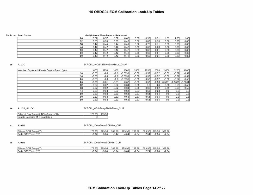
Table no. Fault Codes Label (Internal Manufacturer Reference)26 0.57 0.57 0.57 0.62 0.82 0.90 0.91 1.03 1.03 1.0332 0.53 0.53 0.53 0.46 0.66 0.80 0.76 0.88 0.88 0.8838 0.44 0.44 0.44 0.41 0.62 0.75 0.71 0.83 0.83 0.8344 0.42 0.42 0.42 0.42 0.59 0.65 0.68 0.80 0.80 0.8050 0.42 0.42 0.42 0.42 0.59 0.62 0.61 0.80 0.80 0.8060 0.42 0.42 0.42 0.42 0.59 0.62 0.61 0.80 0.80 0.8080 0.42 0.42 0.42 0.42 0.59 0.62 0.61 0.80 0.80 0.80
75 P11CC SCRChk_rNOxDiffThresBasMinUs_GMAP
Injection Qty (mm^3/rev) / Engine Speed (rpm) 800 1250 1400 1600 2000 2250 2500 3000 3200 400010 -0.60 -0.6 -0.6 -0.5699 -0.58 -0.52 -0.52 -0.52 -0.52 -0.5214 -0.60 -0.6 -0.6 -0.5699 -0.58 -0.52 -0.52 -0.52 -0.52 -0.5220 -0.60 -0.6 -0.6 -0.5699 -0.58 -0.52 -0.52 -0.52 -0.52 -0.5226 -0.61 -0.61 -0.61 -0.62 -0.63 -0.58 -0.58 -0.5601 -0.5601 -0.560132 -0.62 -0.62 -0.62 -0.64 -0.65 -0.6 -0.6 -0.58 -0.58 -0.5838 -0.62 -0.62 -0.62 -0.64 -0.66 -0.62 -0.62 -0.59 -0.59 -0.5944 -0.63 -0.63 -0.63 -0.64 -0.67 -0.63 -0.63 -0.6 -0.6 -0.650 -0.63 -0.63 -0.63 -0.64 -0.67 -0.64 -0.64 -0.6 -0.6 -0.660 -0.63 -0.63 -0.63 -0.64 -0.67 -0.64 -0.64 -0.6 -0.6 -0.680 -0.63 -0.63 -0.63 -0.64 -0.67 -0.64 -0.64 -0.6 -0.6 -0.6
76 P11CB, P11CC SCRChk_stExhTempRlsUsPlaus_CUR
Exhaust Gas Temp @ NOx Sensor (°C) 179.96 199.96Enable Condition (1 = Enable) (-) 0 1
77 P20EE SCRChk_tDeltaTempSCRMax_CUR
Filtered SCR Temp (°C) 179.96 229.96 249.96 279.96 299.96 309.96 319.96 399.96Delta SCR Temp (°C) -3.04 -3.04 -3.44 -4.04 -2.84 -2.54 -2.34 -2.04
78 P20EE SCRChk_tDeltaTempSCRMin_CUR
Filtered SCR Temp (°C) 179.96 229.96 249.96 279.96 299.96 309.96 319.96 399.96Delta SCR Temp (°C) -3.04 -3.04 -3.24 -3.64 -2.54 -2.24 -2.04 -2.04
15 OBDG04 ECM Calibration Look-Up Tables
ECM Calibration Look-Up Tables Page 14 of 22

Table no. Fault Codes Label (Internal Manufacturer Reference)
79 P20EE SCRChk_tiAddDisbl_MAP
Nox Peak Duration (s) / Nox Mass Flow (g/s) 0 0.08 0.1 0.15 0.2 0.3 0.4 1.650 0 0 5 5 5 5 5 51 0 0 5 5 5 5 5 52 0 0 5 5 5 5 5 55 0 0 5 10 10 10 10 10
10 0 0 10 20 20 20 20 2060 0 0 30 60 60 60 60 60
120 60 60 60 60 60 60 60 601000 60 60 60 60 60 60 60 60
80 P10D0 SCRPOD_tMaxDiff_CUR
Engine Off Time (sec) 0 299 300 28799 28800 32000 32500 32767Delta Temperature (°C) 3276.7 3276.7 3276.7 3276.7 30 30 30 30
81 Engine Running StSys_nStrtCutOut_MAP
BARO Pressure (kPa) / ECT at Start (°C) -40.04 -20.04 -10.04 -0.04 29.96 38.96 39.96 59.9657.7 1100 1100 1000 1000 1000 1000 850 85061.6 1100 1100 1000 1000 1000 1000 850 85065.8 1100 1100 1000 1000 1000 1000 850 85070.1 1100 1100 1000 1000 1000 1000 850 85074.5 1100 1100 1000 1000 1000 1000 850 85079.5 1100 1100 1000 1000 1000 1000 850 850
83 1100 1100 1000 1000 1000 1000 850 850101.3 1100 1100 1000 1000 1000 1000 850 850
82 P01CB, P01CC, P01CD, P01CE, P01CF, P01D0, P01D1,P01D2, P02CD, P02CF, P02D1, P02D3
ZFC_stGearRls_CA
Gear (-) 0 1 2 3 4 5 6 7 8(-) 0 0 0 1 1 1 1 0 0
15 OBDG04 ECM Calibration Look-Up Tables
ECM Calibration Look-Up Tables Page 15 of 22

Table no. Fault Codes Label (Internal Manufacturer Reference)83 P01CB, P01CC, P01CD, P01CE, P01CF, P01D0, P01D1,
P01D2, P02CD, P02CF, P02D1, P02D3 ZFC_tiCldCham_CUR
ECT (°C) -7.04 -5.04 0.96 5.96 13.96 18.96 24.96 29.96 37.96 49.96 59.96 69.96Time (sec) 7 8 10 11 15 17 20 20 20 20 20 20
84 P2263 PCR_facOvrBstDvt_CUR
BARO Pressure (kPa) 70 75 80 85 90 95 100 125Correction Factor (-) 1.25 1.25 1.25 1.20 1.00 1.00 1.00 1.00
85 P2263 PCR_facUndrBstDvt_CUR
BARO Pressure (kPa) 70 75 80 85 90 95 100 125Correction Factor (-) 0.85 0.85 0.90 0.95 1.00 1.00 1.00 1.00
86 P11CB SCRChk_facEnvPCorMaxNOxUs_CUR
BARO Pressure (kPa) 70 75 80 85 90 95 100 110 120Correction Factor (-) 1.40 1.40 1.75 1.72 1.40 1.00 1.00 1.00 1.00
87 P11CC SCRChk_facEnvPCorMinNOxUs_CUR
BARO Pressure (kPa) 70 75 80 85 90 95 100 110 120Correction Factor (-) 0.62 0.62 0.70 0.72 0.85 1.00 1.00 1.00 1.00
end S1-15OBDG05 - Calibration Tables
S2-15OBDG05_PM_Sensor - Calibration Tables
15 OBDG04 ECM Calibration Look-Up Tables
ECM Calibration Look-Up Tables Page 16 of 22

Table no. Fault Codes Label (Internal Manufacturer Reference)
Table no. Fault Codes Label (Internal Manufacturer Reference)
1 P24C7 Exh_tPPDsTempMeaDifNeg_CUR
Exhaust Temperature Average (deg C) -0.04 49.96 139.96 159.96 179.96 239.96 299.96 399.96Diagnostic Threshold (deg C) -30.04 -30.04 -70.04 -75.04 -80.04 -95.04 -110.04 -155.04
2 P24C7 Exh_tPPDsTempMeaDifPos_CUR
Exhaust Temperature Average (deg C) -0.04 49.96 139.96 159.96 179.96 239.96 299.96 399.96Diagnostic Threshold (deg C) 69.96 69.96 109.96 114.96 119.96 134.96 149.96 194.96
end S1-15OBDG05_PM_Sensor - Calibration Tables
Calibration Parameter Definition - Calibration TablesStatus and State Calibration Tables
Table no. Status or State Label (Internal Manufacturer Reference)
1 A/F Sensor Dewpoint Reached,Status of NOx signal of upstream NOx sensor,Upstream NOx sensor dewpoint achieved
DewDet_wThresLSU0_MAP
ECT at Start (°C) / Modeled Exhaust Wall Temp (°C) -40.14 -30.04 -20.04 -10.04 -0.04 9.96 19.96 29.96-40.14 600 600 600 600 600 600 600 600
15 OBDG04 ECM Calibration Look-Up Tables
ECM Calibration Look-Up Tables Page 17 of 22
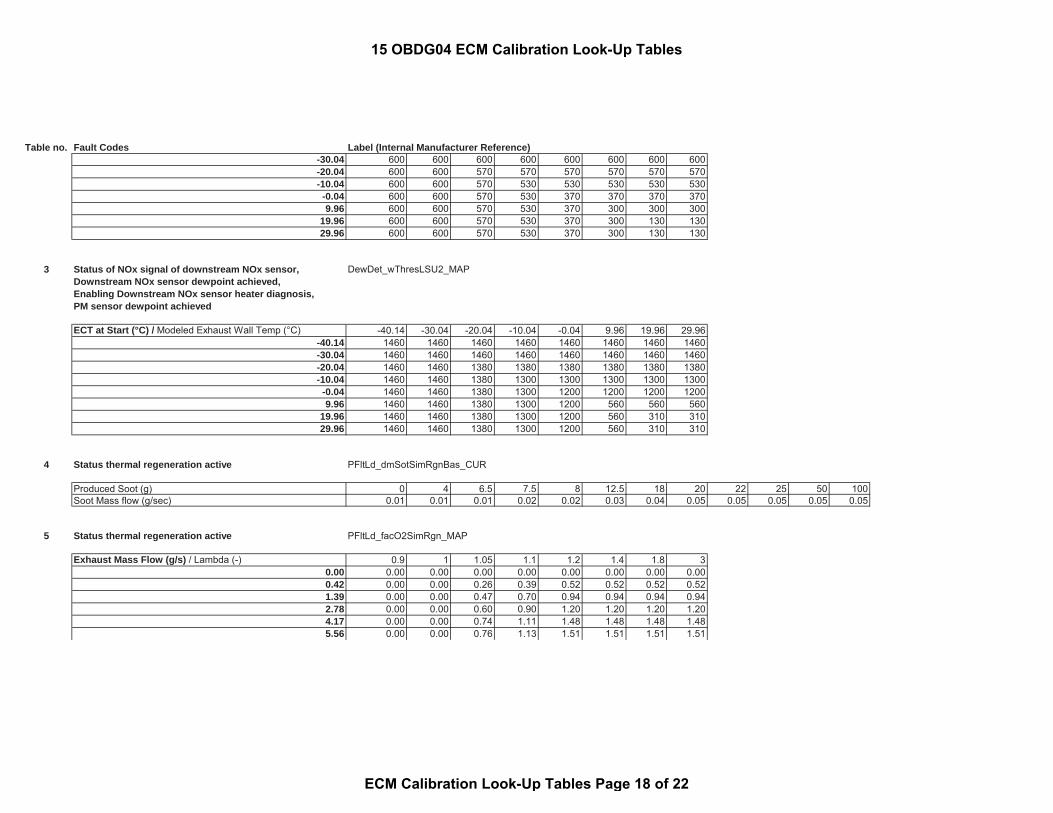
Table no. Fault Codes Label (Internal Manufacturer Reference)-30.04 600 600 600 600 600 600 600 600-20.04 600 600 570 570 570 570 570 570-10.04 600 600 570 530 530 530 530 530
-0.04 600 600 570 530 370 370 370 3709.96 600 600 570 530 370 300 300 300
19.96 600 600 570 530 370 300 130 13029.96 600 600 570 530 370 300 130 130
3 Status of NOx signal of downstream NOx sensor,Downstream NOx sensor dewpoint achieved,Enabling Downstream NOx sensor heater diagnosis,PM sensor dewpoint achieved
DewDet_wThresLSU2_MAP
ECT at Start (°C) / Modeled Exhaust Wall Temp (°C) -40.14 -30.04 -20.04 -10.04 -0.04 9.96 19.96 29.96-40.14 1460 1460 1460 1460 1460 1460 1460 1460-30.04 1460 1460 1460 1460 1460 1460 1460 1460-20.04 1460 1460 1380 1380 1380 1380 1380 1380-10.04 1460 1460 1380 1300 1300 1300 1300 1300
-0.04 1460 1460 1380 1300 1200 1200 1200 12009.96 1460 1460 1380 1300 1200 560 560 560
19.96 1460 1460 1380 1300 1200 560 310 31029.96 1460 1460 1380 1300 1200 560 310 310
4 Status thermal regeneration active PFltLd_dmSotSimRgnBas_CUR
Produced Soot (g) 0 4 6.5 7.5 8 12.5 18 20 22 25 50 100Soot Mass flow (g/sec) 0.01 0.01 0.01 0.02 0.02 0.03 0.04 0.05 0.05 0.05 0.05 0.05
5 Status thermal regeneration active PFltLd_facO2SimRgn_MAP
Exhaust Mass Flow (g/s) / Lambda (-) 0.9 1 1.05 1.1 1.2 1.4 1.8 30.00 0.00 0.00 0.00 0.00 0.00 0.00 0.00 0.000.42 0.00 0.00 0.26 0.39 0.52 0.52 0.52 0.521.39 0.00 0.00 0.47 0.70 0.94 0.94 0.94 0.942.78 0.00 0.00 0.60 0.90 1.20 1.20 1.20 1.204.17 0.00 0.00 0.74 1.11 1.48 1.48 1.48 1.485.56 0.00 0.00 0.76 1.13 1.51 1.51 1.51 1.51
15 OBDG04 ECM Calibration Look-Up Tables
ECM Calibration Look-Up Tables Page 18 of 22

Table no. Fault Codes Label (Internal Manufacturer Reference)6.95 0.00 0.00 0.76 1.14 1.53 1.53 1.53 1.539.72 0.00 0.00 0.81 1.22 1.62 1.62 1.62 1.62
6 Status thermal regeneration active PFltLd_facTempSimRgn_CUR
Particulate Filter Surface Temp (°C) 499.96 524.96 549.96 569.96 579.96 589.96 599.96 624.96 649.96 699.96Temperature Factor (-) 0 0.13989 0.22473 0.35376 0.52844 0.67993 0.8 0.9 0.9 0.95
7 Rail Control - PCV Closed Loop Control Only Rail_dvolMeUnCtlUpLim_CUR
Engine Speed (rpm) 500 750 1400 1700 1950 2804 3054 3304 5000 5001 5002 5003 5004 5005 5006 5007Rail Volume Flow (mm^3/sec) 20000 20000 20000 21000 22700 30370 32580 33080 33080 33080 33080 33080 33080 33080 33080 33080
8Rail Control - Metering Unit + PCV Closed Loop Control
Rail_qMeUnCtlType_CUR
Engine Speed (rpm) 850 1025 1200 1300 1500 1700 1900 2100Injection Qty (mm^3/rev) 9 14 20 24 26 24 21 20
9 Status of the SCR adaptation plausibility check active SCRAd_mNH3MinTrg_MAP
SCR Modeled Efficieny (- )/ SCR Temp (°C) -0.04 99.96 299.86 299.96 399.96 499.960 0 0 0 0.04 0.04 0.04
0.2 0 0 0 0.04 0.04 0.040.4 0 0 0 0.04 0.04 0.040.6 0 0 0 0.04 0.04 0.040.8 0 0 0 0.04 0.04 0.04
1 0 0 0 0.04 0.04 0.04
10 Overdosing detected SCRAd_mNOxOvrMetPh1_CUR
SCR Avg. Temp (°C) 249.96 299.96 349.96 399.96Nox Mass (g) -0.55 -0.45 -0.4 -0.38
11 Overdosing detected SCRAd_mNOxOvrMetPh2_CUR
15 OBDG04 ECM Calibration Look-Up Tables
ECM Calibration Look-Up Tables Page 19 of 22

Table no. Fault Codes Label (Internal Manufacturer Reference)
SCR Avg. Temp (°C) 249.96 299.96 349.96 399.96Nox Mass (g) -0.39 -0.34 -0.3 -0.3
12 Overdosing detected SCRAd_mNOxOvrMetPh3_CUR
SCR Avg. Temp (°C) 249.96 299.96 349.96 399.96Nox Mass (g) -0.27 -0.23 -0.2 -0.2
13 Underdosing detected SCRAd_mNOxUndrMetPh1_CUR
SCR Avg. Temp (°C) 249.96 299.96 349.96 399.96Nox Mass (g) 0.45 0.42 0.4 0.4
14 Underdosing detected SCRAd_mNOxUndrMetPh2_CUR
SCR Avg. Temp (°C) 249.96 299.96 349.96 399.96Nox Mass (g) 0.09 0.08 0.08 0.08
15 Underdosing detected SCRAd_mNOxUndrMetPh3_CUR
SCR Avg. Temp (°C) 249.96 299.96 349.96 399.96Nox Mass (g) -0.1 -0.08 -0.07 -0.07
16 State of Reductant injection valve Component Protection UDC_tUDosVlvCoPrActv_MAP
Vehicle Speed (mph) / Exhaust Gas Temp (°C) 199.96 299.96 399.96 499.96 599.960 134.96 134.96 129.96 119.96 119.96
31.25 124.96 124.96 124.96 119.96 119.96125 119.96 119.96 119.96 119.96 119.96
17 Release of tank heater circuit UHC_tiC1On_CUR
Reductant Tank Temp. (°C) -30.04 -7.04 -6.04 -0.04
15 OBDG04 ECM Calibration Look-Up Tables
ECM Calibration Look-Up Tables Page 20 of 22

Table no. Fault Codes Label (Internal Manufacturer Reference)Reductant Heater Time (sec) 300 300 0 0
18 Release of tank heater circuit UHC_tiDfrstC2_CUR
Reductant Tank Temp. (°C) -45.04 -30.04 -25.04 -18.04 -9.04 -8.04 -6.04Reductant Heater Time (sec) 2200 1800 1600 1200 600 300 0
19 Release of tank heater circuit UHC_tiDfrstC3_CUR
Reductant Tank Temp. (°C) -45.04 -30.04 -25.04 -18.04 -9.04 -8.04 -6.04Reductant Heater Time (sec) 2200 1800 1600 1200 600 300 0
20 State of the defrosting check of supply module UHC_tiEngOffC3FrzLim_CUR
Reductant Tank Temp. (°C) -30.04 -25.04 -20.04 -15.04 -11.04 -5.04Engine Off Time (sec) 120 120 120 180 550 900
21 State of the defrosting check of pressure line UHC_tiEngOffFrzLim_CUR
Reductant Tank Temp. (°C) -30.04 -25.04 -20.04 -15.04 -11.04 -5.04Engine Off Time (sec) 120 120 120 180 550 900
22 Release of tank heater circuitRelease of pressure line heater circuit
UHC_tiOnC2_CUR
Reductant Tank Temp. (°C) -60.04 -7.04 -6.04 9.96Reductant Heater Time (sec) 180 180 0 0
23 Release of tank heater circuitRelease of pressure line heater circuit
UHC_tiOnC3_CUR
Reductant Tank Temp. (°C) -60.04 -7.04 -6.04 9.96Reductant Heater Time (sec) 180 180 0 0
24 Release of tank heater circuit UHC_tiC1DfrstFirstCyc_MAP
15 OBDG04 ECM Calibration Look-Up Tables
ECM Calibration Look-Up Tables Page 21 of 22

Table no. Fault Codes Label (Internal Manufacturer Reference)
Ambient Air Temp (°C) / Reductant Tank Temp (°C) -45.04 -30.04 -25.04 -18.04 -9.04 -8.04 -6.04-45.04 4170 3270 2670 1800 1200 600 10-25.04 4170 3270 2670 1800 1200 600 10-18.04 4170 3270 2670 1800 1200 600 10
-9.04 4170 3270 2670 1800 1200 600 10-8.04 4170 3270 2670 1800 1200 600 10-5.04 4170 3270 2670 1800 1200 600 109.96 4170 3270 2670 1800 1200 600 10
19.96 4170 3270 2670 1800 1200 600 10
15 OBDG04 ECM Calibration Look-Up Tables
ECM Calibration Look-Up Tables Page 22 of 22

Active DTCP0016 - Crankshaft to Camshaft
CorrelationP0315 - Crankshaft Position System
Variation Not Learned
P0030 - HO2S Heater ControlCircuit Bank 1 Sensor 1
P0133 - O2 Sensor Circuit SlowResponse Bank 1 Sensor 1
P11A6 - HO2S Performance - SignalHigh During Moderate Load Sensor 1
P11A9 - O2 Sensor Performance -Signal Low During Moderate Load
Bank 1 Sensor 1
P2237 - O2 Sensor Positive CurrentControl Circuit/Open Bank 1 Sensor
1
P2243 - O2 Sensor ReferenceVoltage Circuit/Open Bank 1 Sensor
1
P2251 - O2 Sensor Negative CurrentControl Circuit/Open Bank 1 Sensor
1
P2A00 - O2 Sensor CircuitRange/Performance Bank 1 Sensor 1
P0031 - HO2S Heater ControlCircuit Low Bank 1 Sensor 1
P0133 - O2 Sensor Circuit SlowResponse Bank 1 Sensor 1
P11A6 - HO2S Performance - SignalHigh During Moderate Load Sensor 1
P11A9 - O2 Sensor Performance -Signal Low During Moderate Load
Bank 1 Sensor 1
P2237 - O2 Sensor Positive CurrentControl Circuit/Open Bank 1 Sensor
1
P2243 - O2 Sensor ReferenceVoltage Circuit/Open Bank 1 Sensor
1
P2251 - O2 Sensor Negative CurrentControl Circuit/Open Bank 1 Sensor
1
P2A00 - O2 Sensor CircuitRange/Performance Bank 1 Sensor 1
P0032 - HO2S Heater ControlCircuit High Bank 1 Sensor 1
P0133 - O2 Sensor Circuit SlowResponse Bank 1 Sensor 1
P11A6 - HO2S Performance - SignalHigh During Moderate Load Sensor 1
P11A9 - O2 Sensor Performance -Signal Low During Moderate Load
Bank 1 Sensor 1
P2237 - O2 Sensor Positive CurrentControl Circuit/Open Bank 1 Sensor
1
P2243 - O2 Sensor ReferenceVoltage Circuit/Open Bank 1 Sensor
1
P2251 - O2 Sensor Negative CurrentControl Circuit/Open Bank 1 Sensor
1
P2A00 - O2 Sensor CircuitRange/Performance Bank 1 Sensor 1
P0047 - Turbocharger BoostControl Circuit Low Voltage
P0133 - O2 Sensor Circuit SlowResponse Bank 1 Sensor 1
P0234 - Turbocharger EngineOverboost
P0299 - Turbocharger EngineUnderboost
P0401 - Exhaust Gas RecirculationFlow Insufficient
P0402 - Exhaust Gas RecirculationFlow Excessive
P11A6 - HO2S Performance - SignalHigh During Moderate Load Sensor 1
P11A9 - O2 Sensor Performance -Signal Low During Moderate Load
Bank 1 Sensor 1
P2002 - Diesel Particulate Filter(DPF) Low Efficiency
P2237 - O2 Sensor Positive CurrentControl Circuit/Open Bank 1 Sensor
1
P2A00 - O2 Sensor CircuitRange/Performance Bank 1 Sensor 1
P0048 - Turbocharger BoostControl Circuit High Voltage
P0133 - O2 Sensor Circuit SlowResponse Bank 1 Sensor 1
P0234 - Turbocharger EngineOverboost
P0299 - Turbocharger EngineUnderboost
P0401 - Exhaust Gas RecirculationFlow Insufficient
P0402 - Exhaust Gas RecirculationFlow Excessive
P11A6 - HO2S Performance - SignalHigh During Moderate Load Sensor 1
P11A9 - O2 Sensor Performance -Signal Low During Moderate Load
Bank 1 Sensor 1
P2002 - Diesel Particulate Filter(DPF) Low Efficiency
P2237 - O2 Sensor Positive CurrentControl Circuit/Open Bank 1 Sensor
1
P2A00 - O2 Sensor CircuitRange/Performance Bank 1 Sensor 1
P007C - CAC Temperature SensorCircuit Low Voltage
P0171 - System Too Lean Bank 1 P0172 - System Too Rich Bank 1 P01CB - Cylinder 1 Injection TimingRetarded
P01CC - Cylinder 1 Injection TimingAdvanced
P01CD - Cylinder 2 Injection TimingRetarded
P01CE - Cylinder 2 Injection TimingAdvanced
P01CF - Cylinder 3 Injection TimingRetarded
P01D0 - Cylinder 3 Injection TimingAdvanced
P01D1 - Cylinder 4 Injection TimingRetarded
P01D2 - Cylinder 4 Injection TimingAdvanced
P0234 - Turbocharger EngineOverboost
P026C - Injection Quantity Too Low P026D - Injection Quantity Too High P0299 - Turbocharger EngineUnderboost
P007D - CAC Temperature SensorCircuit High Voltage
P0171 - System Too Lean Bank 1 P0172 - System Too Rich Bank 1 P01CB - Cylinder 1 Injection TimingRetarded
P01CC - Cylinder 1 Injection TimingAdvanced
P01CD - Cylinder 2 Injection TimingRetarded
P01CE - Cylinder 2 Injection TimingAdvanced
P01CF - Cylinder 3 Injection TimingRetarded
P01D0 - Cylinder 3 Injection TimingAdvanced
P01D1 - Cylinder 4 Injection TimingRetarded
P01D2 - Cylinder 4 Injection TimingAdvanced
P0234 - Turbocharger EngineOverboost
P026C - Injection Quantity Too Low P026D - Injection Quantity Too High P0299 - Turbocharger EngineUnderboost
P0401 - Exhaust Gas RecirculationFlow Insufficient
P0402 - Exhaust Gas RecirculationFlow Excessive
P168A P168B
P0401 - Exhaust Gas RecirculationFlow Insufficient
P0402 - Exhaust Gas RecirculationFlow Excessive
P168A P168B
P0087 - Fuel Rail/SystemPressure - Too Low Bank 1
P2002 - Diesel Particulate Filter(DPF) Low Efficiency
P0088 - Fuel Rail Pressure TooHigh
P2002 - Diesel Particulate Filter(DPF) Low Efficiency
P0091 - Fuel Pressure Regulator 1Control Circuit Low
P2002 - Diesel Particulate Filter(DPF) Low Efficiency
P0092 - Fuel Pressure Regulator 1Control Circuit High
P2002 - Diesel Particulate Filter(DPF) Low Efficiency
P0102 - Mass Air Flow SensorCircuit Low
P0128 - Engine Coolant TemperatureBelow Thermostat Regulating
Temperature
P0133 - O2 Sensor Circuit SlowResponse Bank 1 Sensor 1
P0234 - Turbocharger EngineOverboost
P0299 - Turbocharger EngineUnderboost
P0401 - Exhaust Gas RecirculationFlow Insufficient
P0402 - Exhaust Gas RecirculationFlow Excessive
P0420 - NMHC Catalyst EfficiencyBelow Threshold Bank 1
P11A6 - HO2S Performance - SignalHigh During Moderate Load Sensor 1
P11A9 - O2 Sensor Performance -Signal Low During Moderate Load
Bank 1 Sensor 1
P2237 - O2 Sensor Positive CurrentControl Circuit/Open Bank 1 Sensor
1
P2459 - Diesel Particulate FilterRegeneration Frequency
P24B4 - Particulate Matter SensorHeater Control CircuitRange/Performance
P0107 - Manifold AbsolutePressure (MAP) Sensor Circuit
Low Voltage
P01CB - Cylinder 1 Injection TimingRetarded
P01CC - Cylinder 1 Injection TimingAdvanced
P01CD - Cylinder 2 Injection TimingRetarded
P01CE - Cylinder 2 Injection TimingAdvanced
P01CF - Cylinder 3 Injection TimingRetarded
P01D0 - Cylinder 3 Injection TimingAdvanced
P01D1 - Cylinder 4 Injection TimingRetarded
P01D2 - Cylinder 4 Injection TimingAdvanced
P0234 - Turbocharger EngineOverboost
P0299 - Turbocharger EngineUnderboost
P0401 - Exhaust Gas RecirculationFlow Insufficient
P0402 - Exhaust Gas RecirculationFlow Excessive
P24B4 - Particulate Matter SensorHeater Control CircuitRange/Performance
P0108 - Manifold AbsolutePressure (MAP) Sensor Circuit
High Voltage
P01CB - Cylinder 1 Injection TimingRetarded
P01CC - Cylinder 1 Injection TimingAdvanced
P01CD - Cylinder 2 Injection TimingRetarded
P01CE - Cylinder 2 Injection TimingAdvanced
P01CF - Cylinder 3 Injection TimingRetarded
P01D0 - Cylinder 3 Injection TimingAdvanced
P01D1 - Cylinder 4 Injection TimingRetarded
P01D2 - Cylinder 4 Injection TimingAdvanced
P0234 - Turbocharger EngineOverboost
P0299 - Turbocharger EngineUnderboost
P0401 - Exhaust Gas RecirculationFlow Insufficient
P0402 - Exhaust Gas RecirculationFlow Excessive
P24B4 - Particulate Matter SensorHeater Control CircuitRange/Performance
P0112 - Intake Air TemperatureSensor 1 Circuit Low
P0128 - Engine Coolant TemperatureBelow Thermostat Regulating
Temperature
P0401 - Exhaust Gas RecirculationFlow Insufficient
P0402 - Exhaust Gas RecirculationFlow Excessive
P040F - Exhaust Gas Recirculation(EGR) Temperature Sensor 1-2
Correlation
P0420 - NMHC Catalyst EfficiencyBelow Threshold Bank 1
P20E2 - Exhaust Gas Temperature(EGT) Sensors 1-2 not plausible
P0113 - Intake Air TemperatureSensor 1 Circuit High
P0128 - Engine Coolant TemperatureBelow Thermostat Regulating
Temperature
P0401 - Exhaust Gas RecirculationFlow Insufficient
P0402 - Exhaust Gas RecirculationFlow Excessive
P040F - Exhaust Gas Recirculation(EGR) Temperature Sensor 1-2
Correlation
P0420 - NMHC Catalyst EfficiencyBelow Threshold Bank 1
P20E2 - Exhaust Gas Temperature(EGT) Sensors 1-2 not plausible
P0117 - Engine CoolantTemperature Sensor Circuit Low
P0128 - Engine Coolant TemperatureBelow Thermostat Regulating
Temperature
P01CB - Cylinder 1 Injection TimingRetarded
P01CC - Cylinder 1 Injection TimingAdvanced
P01CD - Cylinder 2 Injection TimingRetarded
P01CE - Cylinder 2 Injection TimingAdvanced
P01CF - Cylinder 3 Injection TimingRetarded
P01D0 - Cylinder 3 Injection TimingAdvanced
P01D1 - Cylinder 4 Injection TimingRetarded
P01D2 - Cylinder 4 Injection TimingAdvanced
P0234 - Turbocharger EngineOverboost
P0263 - Cly 1 Balance System P0266 - Cly 2 Balance System P0269 - Cly 3 Balance System P0272 - Cly 4 Balance System
P0118 - Engine CoolantTemperature Sensor Circuit High
P0128 - Engine Coolant TemperatureBelow Thermostat Regulating
Temperature
P01CB - Cylinder 1 Injection TimingRetarded
P01CC - Cylinder 1 Injection TimingAdvanced
P01CD - Cylinder 2 Injection TimingRetarded
P01CE - Cylinder 2 Injection TimingAdvanced
P01CF - Cylinder 3 Injection TimingRetarded
P01D0 - Cylinder 3 Injection TimingAdvanced
P01D1 - Cylinder 4 Injection TimingRetarded
P01D2 - Cylinder 4 Injection TimingAdvanced
P0234 - Turbocharger EngineOverboost
P0263 - Cly 1 Balance System P0266 - Cly 2 Balance System P0269 - Cly 3 Balance System P0272 - Cly 4 Balance System
P0299 - Turbocharger EngineUnderboost
P0300 - Engine Misfire Detected P0301 - Cylinder 1 Misfire Detected P0302 - Cylinder 2 Misfire Detected P0303 - Cylinder 3 Misfire Detected P0304 - Cylinder 4 Misfire Detected P0401 - Exhaust Gas RecirculationFlow Insufficient
P0402 - Exhaust Gas RecirculationFlow Excessive
P0420 - NMHC Catalyst EfficiencyBelow Threshold Bank 1
P0506 - Idle Speed Low P0507 - Idle Speed High
P011B - Engine CoolantTemperature/Intake Air
Temperature Correlation
P0420 - NMHC Catalyst EfficiencyBelow Threshold Bank 1
P0128 - Engine CoolantTemperature Below Thermostat
Regulating Temperature
P01F0 - Coolant TemperatureDropped Below Diagnostic Monitoring
Temperature
P0131 - HO2S Bank 1 Sensor 1circuit low
P0132 - HO2S Bank 1 Sensor 1circuit high
P0133 - O2 Sensor Circuit SlowResponse Bank 1 Sensor 1
P11A6 - HO2S Performance - SignalHigh During Moderate Load Sensor 1
P11A9 - O2 Sensor Performance -Signal Low During Moderate Load
Bank 1 Sensor 1
P2002 - Diesel Particulate Filter(DPF) Low Efficiency
P2237 - O2 Sensor Positive CurrentControl Circuit/Open Bank 1 Sensor
1
P2243 - O2 Sensor ReferenceVoltage Circuit/Open Bank 1 Sensor
1
P2251 - O2 Sensor Negative CurrentControl Circuit/Open Bank 1 Sensor
1
P2A00 - O2 Sensor CircuitRange/Performance Bank 1 Sensor 1
P0132 - HO2S Bank 1 Sensor 1circuit high
P0131 - HO2S Bank 1 Sensor 1circuit low
P0133 - O2 Sensor Circuit SlowResponse Bank 1 Sensor 1
P11A6 - HO2S Performance - SignalHigh During Moderate Load Sensor 1
P11A9 - O2 Sensor Performance -Signal Low During Moderate Load
Bank 1 Sensor 1
P2002 - Diesel Particulate Filter(DPF) Low Efficiency
P2237 - O2 Sensor Positive CurrentControl Circuit/Open Bank 1 Sensor
1
P2243 - O2 Sensor ReferenceVoltage Circuit/Open Bank 1 Sensor
1
P2251 - O2 Sensor Negative CurrentControl Circuit/Open Bank 1 Sensor
1
P2A00 - O2 Sensor CircuitRange/Performance Bank 1 Sensor 1
P0133 - O2 Sensor Circuit SlowResponse Bank 1 Sensor 1
P2002 - Diesel Particulate Filter(DPF) Low Efficiency
P0171 - System Too Lean Bank 1 P11CB - NOx Sensor Performance -Signal High Bank 1 Sensor 1
P11CC - NOx Sensor Performance -Signal Low Bank 1 Sensor 1
P2002 - Diesel Particulate Filter(DPF) Low Efficiency
P0172 - System Too Rich Bank 1 P11CB - NOx Sensor Performance -Signal High Bank 1 Sensor 1
P11CC - NOx Sensor Performance -Signal Low Bank 1 Sensor 1
P2002 - Diesel Particulate Filter(DPF) Low Efficiency
P0182 - Fuel Temperature Sensor1 Circuit Low
P01CB - Cylinder 1 Injection TimingRetarded
P01CC - Cylinder 1 Injection TimingAdvanced
P01CD - Cylinder 2 Injection TimingRetarded
P01CE - Cylinder 2 Injection TimingAdvanced
P01CF - Cylinder 3 Injection TimingRetarded
P01D0 - Cylinder 3 Injection TimingAdvanced
P01D1 - Cylinder 4 Injection TimingRetarded
P01D2 - Cylinder 4 Injection TimingAdvanced
P0183 - Fuel Temperature Sensor1 Circuit High
P01CB - Cylinder 1 Injection TimingRetarded
P01CC - Cylinder 1 Injection TimingAdvanced
P01CD - Cylinder 2 Injection TimingRetarded
P01CE - Cylinder 2 Injection TimingAdvanced
P01CF - Cylinder 3 Injection TimingRetarded
P01D0 - Cylinder 3 Injection TimingAdvanced
P01D1 - Cylinder 4 Injection TimingRetarded
P01D2 - Cylinder 4 Injection TimingAdvanced
P0192 - Fuel Rail Pressure SensorCircuit Low
P01CB - Cylinder 1 Injection TimingRetarded
P01CC - Cylinder 1 Injection TimingAdvanced
P01CD - Cylinder 2 Injection TimingRetarded
P01CE - Cylinder 2 Injection TimingAdvanced
P01CF - Cylinder 3 Injection TimingRetarded
P01D0 - Cylinder 3 Injection TimingAdvanced
P01D1 - Cylinder 4 Injection TimingRetarded
P01D2 - Cylinder 4 Injection TimingAdvanced
P2002 - Diesel Particulate Filter(DPF) Low Efficiency
P0193 - Fuel Rail Pressure SensorCircuit High
P01CB - Cylinder 1 Injection TimingRetarded
P01CC - Cylinder 1 Injection TimingAdvanced
P01CD - Cylinder 2 Injection TimingRetarded
P01CE - Cylinder 2 Injection TimingAdvanced
P01CF - Cylinder 3 Injection TimingRetarded
P01D0 - Cylinder 3 Injection TimingAdvanced
P01D1 - Cylinder 4 Injection TimingRetarded
P01D2 - Cylinder 4 Injection TimingAdvanced
P2002 - Diesel Particulate Filter(DPF) Low Efficiency
P01CB - Cylinder 1 InjectionTiming Retarded
P2002 - Diesel Particulate Filter(DPF) Low Efficiency
P01CC - Cylinder 1 InjectionTiming Advanced
P2002 - Diesel Particulate Filter(DPF) Low Efficiency
P01CD - Cylinder 2 InjectionTiming Retarded
P2002 - Diesel Particulate Filter(DPF) Low Efficiency
P01CE - Cylinder 2 InjectionTiming Advanced
P2002 - Diesel Particulate Filter(DPF) Low Efficiency
P01CF - Cylinder 3 InjectionTiming Retarded
P2002 - Diesel Particulate Filter(DPF) Low Efficiency
P01D0 - Cylinder 3 InjectionTiming Advanced
P2002 - Diesel Particulate Filter(DPF) Low Efficiency
P01D1 - Cylinder 4 InjectionTiming Retarded
P2002 - Diesel Particulate Filter(DPF) Low Efficiency
P01D2 - Cylinder 4 InjectionTiming Advanced
P2002 - Diesel Particulate Filter(DPF) Low Efficiency
P0201 - Injector 1 Control Circuit P0171 - System Too Lean Bank 1 P0172 - System Too Rich Bank 1 P01CB - Cylinder 1 Injection TimingRetarded
P01CC - Cylinder 1 Injection TimingAdvanced
P01CD - Cylinder 2 Injection TimingRetarded
P01CE - Cylinder 2 Injection TimingAdvanced
P01CF - Cylinder 3 Injection TimingRetarded
P01D0 - Cylinder 3 Injection TimingAdvanced
P01D1 - Cylinder 4 Injection TimingRetarded
P01D2 - Cylinder 4 Injection TimingAdvanced
P026C - Injection Quantity Too Low P026D - Injection Quantity Too High
P0202 - Injector 2 Control Circuit P0171 - System Too Lean Bank 1 P0172 - System Too Rich Bank 1 P01CB - Cylinder 1 Injection TimingRetarded
P01CC - Cylinder 1 Injection TimingAdvanced
P01CD - Cylinder 2 Injection TimingRetarded
P01CE - Cylinder 2 Injection TimingAdvanced
P01CF - Cylinder 3 Injection TimingRetarded
P01D0 - Cylinder 3 Injection TimingAdvanced
P01D1 - Cylinder 4 Injection TimingRetarded
P01D2 - Cylinder 4 Injection TimingAdvanced
P026C - Injection Quantity Too Low P026D - Injection Quantity Too High
Inhibited DTCs
15 OBDG04 ECM Diagnostic Inhibit Tables
ECM Diagnostic Inhibit Tables Page 1 of 5
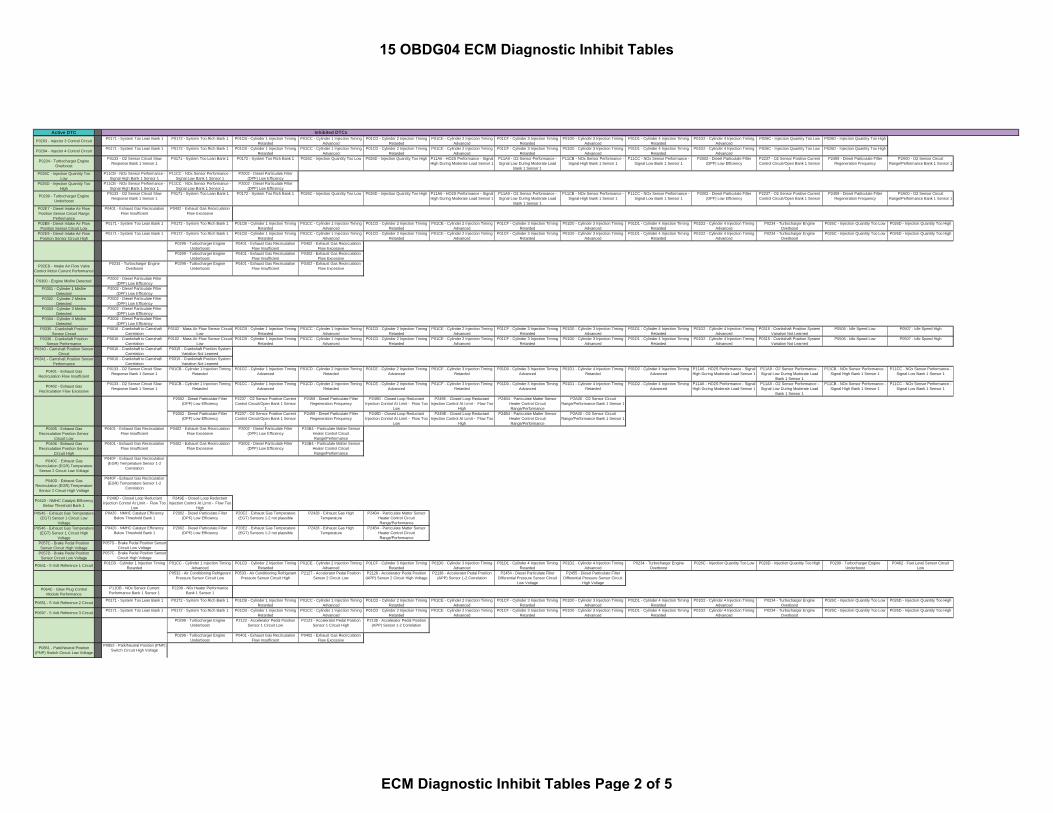
Active DTC Inhibited DTCs
P0203 - Injector 3 Control Circuit P0171 - System Too Lean Bank 1 P0172 - System Too Rich Bank 1 P01CB - Cylinder 1 Injection TimingRetarded
P01CC - Cylinder 1 Injection TimingAdvanced
P01CD - Cylinder 2 Injection TimingRetarded
P01CE - Cylinder 2 Injection TimingAdvanced
P01CF - Cylinder 3 Injection TimingRetarded
P01D0 - Cylinder 3 Injection TimingAdvanced
P01D1 - Cylinder 4 Injection TimingRetarded
P01D2 - Cylinder 4 Injection TimingAdvanced
P026C - Injection Quantity Too Low P026D - Injection Quantity Too High
P0204 - Injector 4 Control Circuit P0171 - System Too Lean Bank 1 P0172 - System Too Rich Bank 1 P01CB - Cylinder 1 Injection TimingRetarded
P01CC - Cylinder 1 Injection TimingAdvanced
P01CD - Cylinder 2 Injection TimingRetarded
P01CE - Cylinder 2 Injection TimingAdvanced
P01CF - Cylinder 3 Injection TimingRetarded
P01D0 - Cylinder 3 Injection TimingAdvanced
P01D1 - Cylinder 4 Injection TimingRetarded
P01D2 - Cylinder 4 Injection TimingAdvanced
P026C - Injection Quantity Too Low P026D - Injection Quantity Too High
P0234 - Turbocharger EngineOverboost
P0133 - O2 Sensor Circuit SlowResponse Bank 1 Sensor 1
P0171 - System Too Lean Bank 1 P0172 - System Too Rich Bank 1 P026C - Injection Quantity Too Low P026D - Injection Quantity Too High P11A6 - HO2S Performance - SignalHigh During Moderate Load Sensor 1
P11A9 - O2 Sensor Performance -Signal Low During Moderate Load
Bank 1 Sensor 1
P11CB - NOx Sensor Performance -Signal High Bank 1 Sensor 1
P11CC - NOx Sensor Performance -Signal Low Bank 1 Sensor 1
P2002 - Diesel Particulate Filter(DPF) Low Efficiency
P2237 - O2 Sensor Positive CurrentControl Circuit/Open Bank 1 Sensor
1
P2459 - Diesel Particulate FilterRegeneration Frequency
P2A00 - O2 Sensor CircuitRange/Performance Bank 1 Sensor 1
P026C - Injection Quantity TooLow
P11CB - NOx Sensor Performance -Signal High Bank 1 Sensor 1
P11CC - NOx Sensor Performance -Signal Low Bank 1 Sensor 1
P2002 - Diesel Particulate Filter(DPF) Low Efficiency
P026D - Injection Quantity TooHigh
P11CB - NOx Sensor Performance -Signal High Bank 1 Sensor 1
P11CC - NOx Sensor Performance -Signal Low Bank 1 Sensor 1
P2002 - Diesel Particulate Filter(DPF) Low Efficiency
P0299 - Turbocharger EngineUnderboost
P0133 - O2 Sensor Circuit SlowResponse Bank 1 Sensor 1
P0171 - System Too Lean Bank 1 P0172 - System Too Rich Bank 1 P026C - Injection Quantity Too Low P026D - Injection Quantity Too High P11A6 - HO2S Performance - SignalHigh During Moderate Load Sensor 1
P11A9 - O2 Sensor Performance -Signal Low During Moderate Load
Bank 1 Sensor 1
P11CB - NOx Sensor Performance -Signal High Bank 1 Sensor 1
P11CC - NOx Sensor Performance -Signal Low Bank 1 Sensor 1
P2002 - Diesel Particulate Filter(DPF) Low Efficiency
P2237 - O2 Sensor Positive CurrentControl Circuit/Open Bank 1 Sensor
1
P2459 - Diesel Particulate FilterRegeneration Frequency
P2A00 - O2 Sensor CircuitRange/Performance Bank 1 Sensor 1
P02E7 - Diesel Intake Air FlowPosition Sensor Circuit Range
Performance
P0401 - Exhaust Gas RecirculationFlow Insufficient
P0402 - Exhaust Gas RecirculationFlow Excessive
P02E8 - Diesel Intake Air FlowPosition Sensor Circuit Low
P0171 - System Too Lean Bank 1 P0172 - System Too Rich Bank 1 P01CB - Cylinder 1 Injection TimingRetarded
P01CC - Cylinder 1 Injection TimingAdvanced
P01CD - Cylinder 2 Injection TimingRetarded
P01CE - Cylinder 2 Injection TimingAdvanced
P01CF - Cylinder 3 Injection TimingRetarded
P01D0 - Cylinder 3 Injection TimingAdvanced
P01D1 - Cylinder 4 Injection TimingRetarded
P01D2 - Cylinder 4 Injection TimingAdvanced
P0234 - Turbocharger EngineOverboost
P026C - Injection Quantity Too Low P026D - Injection Quantity Too High
P02E9 - Diesel Intake Air FlowPosition Sensor Circuit High
P0171 - System Too Lean Bank 1 P0172 - System Too Rich Bank 1 P01CB - Cylinder 1 Injection TimingRetarded
P01CC - Cylinder 1 Injection TimingAdvanced
P01CD - Cylinder 2 Injection TimingRetarded
P01CE - Cylinder 2 Injection TimingAdvanced
P01CF - Cylinder 3 Injection TimingRetarded
P01D0 - Cylinder 3 Injection TimingAdvanced
P01D1 - Cylinder 4 Injection TimingRetarded
P01D2 - Cylinder 4 Injection TimingAdvanced
P0234 - Turbocharger EngineOverboost
P026C - Injection Quantity Too Low P026D - Injection Quantity Too High
P0299 - Turbocharger EngineUnderboost
P0401 - Exhaust Gas RecirculationFlow Insufficient
P0402 - Exhaust Gas RecirculationFlow Excessive
P0299 - Turbocharger EngineUnderboost
P0401 - Exhaust Gas RecirculationFlow Insufficient
P0402 - Exhaust Gas RecirculationFlow Excessive
P02EB - Intake Air Flow ValveControl Motor Current Performance
P0234 - Turbocharger EngineOverboost
P0299 - Turbocharger EngineUnderboost
P0401 - Exhaust Gas RecirculationFlow Insufficient
P0402 - Exhaust Gas RecirculationFlow Excessive
P0300 - Engine Misfire Detected P2002 - Diesel Particulate Filter(DPF) Low Efficiency
P0301 - Cylinder 1 MisfireDetected
P2002 - Diesel Particulate Filter(DPF) Low Efficiency
P0302 - Cylinder 2 MisfireDetected
P2002 - Diesel Particulate Filter(DPF) Low Efficiency
P0303 - Cylinder 3 MisfireDetected
P2002 - Diesel Particulate Filter(DPF) Low Efficiency
P0304 - Cylinder 4 MisfireDetected
P2002 - Diesel Particulate Filter(DPF) Low Efficiency
P0335 - Crankshaft PositionSensor Circuit
P0016 - Crankshaft to CamshaftCorrelation
P0102 - Mass Air Flow Sensor CircuitLow
P01CB - Cylinder 1 Injection TimingRetarded
P01CC - Cylinder 1 Injection TimingAdvanced
P01CD - Cylinder 2 Injection TimingRetarded
P01CE - Cylinder 2 Injection TimingAdvanced
P01CF - Cylinder 3 Injection TimingRetarded
P01D0 - Cylinder 3 Injection TimingAdvanced
P01D1 - Cylinder 4 Injection TimingRetarded
P01D2 - Cylinder 4 Injection TimingAdvanced
P0315 - Crankshaft Position SystemVariation Not Learned
P0506 - Idle Speed Low P0507 - Idle Speed High
P0336 - Crankshaft PositionSensor Performance
P0016 - Crankshaft to CamshaftCorrelation
P0102 - Mass Air Flow Sensor CircuitLow
P01CB - Cylinder 1 Injection TimingRetarded
P01CC - Cylinder 1 Injection TimingAdvanced
P01CD - Cylinder 2 Injection TimingRetarded
P01CE - Cylinder 2 Injection TimingAdvanced
P01CF - Cylinder 3 Injection TimingRetarded
P01D0 - Cylinder 3 Injection TimingAdvanced
P01D1 - Cylinder 4 Injection TimingRetarded
P01D2 - Cylinder 4 Injection TimingAdvanced
P0315 - Crankshaft Position SystemVariation Not Learned
P0506 - Idle Speed Low P0507 - Idle Speed High
P0340 - Camshaft Position SensorCircuit
P0016 - Crankshaft to CamshaftCorrelation
P0315 - Crankshaft Position SystemVariation Not Learned
P0341 - Camshaft Position SensorPerformance
P0016 - Crankshaft to CamshaftCorrelation
P0315 - Crankshaft Position SystemVariation Not Learned
P0401 - Exhaust GasRecirculation Flow Insufficient
P0133 - O2 Sensor Circuit SlowResponse Bank 1 Sensor 1
P01CB - Cylinder 1 Injection TimingRetarded
P01CC - Cylinder 1 Injection TimingAdvanced
P01CD - Cylinder 2 Injection TimingRetarded
P01CE - Cylinder 2 Injection TimingAdvanced
P01CF - Cylinder 3 Injection TimingRetarded
P01D0 - Cylinder 3 Injection TimingAdvanced
P01D1 - Cylinder 4 Injection TimingRetarded
P01D2 - Cylinder 4 Injection TimingAdvanced
P11A6 - HO2S Performance - SignalHigh During Moderate Load Sensor 1
P11A9 - O2 Sensor Performance -Signal Low During Moderate Load
Bank 1 Sensor 1
P11CB - NOx Sensor Performance -Signal High Bank 1 Sensor 1
P11CC - NOx Sensor Performance -Signal Low Bank 1 Sensor 1
P0402 - Exhaust GasRecirculation Flow Excessive
P0133 - O2 Sensor Circuit SlowResponse Bank 1 Sensor 1
P01CB - Cylinder 1 Injection TimingRetarded
P01CC - Cylinder 1 Injection TimingAdvanced
P01CD - Cylinder 2 Injection TimingRetarded
P01CE - Cylinder 2 Injection TimingAdvanced
P01CF - Cylinder 3 Injection TimingRetarded
P01D0 - Cylinder 3 Injection TimingAdvanced
P01D1 - Cylinder 4 Injection TimingRetarded
P01D2 - Cylinder 4 Injection TimingAdvanced
P11A6 - HO2S Performance - SignalHigh During Moderate Load Sensor 1
P11A9 - O2 Sensor Performance -Signal Low During Moderate Load
Bank 1 Sensor 1
P11CB - NOx Sensor Performance -Signal High Bank 1 Sensor 1
P11CC - NOx Sensor Performance -Signal Low Bank 1 Sensor 1
P2002 - Diesel Particulate Filter(DPF) Low Efficiency
P2237 - O2 Sensor Positive CurrentControl Circuit/Open Bank 1 Sensor
1
P2459 - Diesel Particulate FilterRegeneration Frequency
P249D - Closed Loop ReductantInjection Control At Limit - Flow Too
Low
P249E - Closed Loop ReductantInjection Control At Limit - Flow Too
High
P24B4 - Particulate Matter SensorHeater Control CircuitRange/Performance
P2A00 - O2 Sensor CircuitRange/Performance Bank 1 Sensor 1
P0405 - Exhaust GasRecirculation Position Sensor
Circuit Low
P0401 - Exhaust Gas RecirculationFlow Insufficient
P0402 - Exhaust Gas RecirculationFlow Excessive
P2002 - Diesel Particulate Filter(DPF) Low Efficiency
P24B4 - Particulate Matter SensorHeater Control CircuitRange/Performance
P0406 - Exhaust GasRecirculation Position Sensor
Circuit High
P0401 - Exhaust Gas RecirculationFlow Insufficient
P0402 - Exhaust Gas RecirculationFlow Excessive
P2002 - Diesel Particulate Filter(DPF) Low Efficiency
P24B4 - Particulate Matter SensorHeater Control CircuitRange/Performance
P040C - Exhaust GasRecirculation (EGR) Temperature
Sensor 2 Circuit Low Voltage
P040F - Exhaust Gas Recirculation(EGR) Temperature Sensor 1-2
Correlation
P040D - Exhaust GasRecirculation (EGR) Temperature
Sensor 2 Circuit High Voltage
P040F - Exhaust Gas Recirculation(EGR) Temperature Sensor 1-2
Correlation
P0420 - NMHC Catalyst EfficiencyBelow Threshold Bank 1
P249D - Closed Loop ReductantInjection Control At Limit - Flow Too
Low
P249E - Closed Loop ReductantInjection Control At Limit - Flow Too
HighP0545 - Exhaust Gas Temperature
(EGT) Sensor 1 Circuit LowVoltage
P0420 - NMHC Catalyst EfficiencyBelow Threshold Bank 1
P2002 - Diesel Particulate Filter(DPF) Low Efficiency
P20E2 - Exhaust Gas Temperature(EGT) Sensors 1-2 not plausible
P2428 - Exhaust Gas HighTemperature
P24B4 - Particulate Matter SensorHeater Control CircuitRange/Performance
P0546 - Exhaust Gas Temperature(EGT) Sensor 1 Circuit High
Voltage
P0420 - NMHC Catalyst EfficiencyBelow Threshold Bank 1
P2002 - Diesel Particulate Filter(DPF) Low Efficiency
P20E2 - Exhaust Gas Temperature(EGT) Sensors 1-2 not plausible
P2428 - Exhaust Gas HighTemperature
P24B4 - Particulate Matter SensorHeater Control CircuitRange/Performance
P057C - Brake Pedal PositionSensor Circuit High Voltage
P057D - Brake Pedal Position SensorCircuit Low Voltage
P057D - Brake Pedal PositionSensor Circuit Low Voltage
P057C - Brake Pedal Position SensorCircuit High Voltage
P0641 - 5 Volt Reference 1 Circuit P01CB - Cylinder 1 Injection TimingRetarded
P01CC - Cylinder 1 Injection TimingAdvanced
P01CD - Cylinder 2 Injection TimingRetarded
P01CE - Cylinder 2 Injection TimingAdvanced
P01CF - Cylinder 3 Injection TimingRetarded
P01D0 - Cylinder 3 Injection TimingAdvanced
P01D1 - Cylinder 4 Injection TimingRetarded
P01D2 - Cylinder 4 Injection TimingAdvanced
P0234 - Turbocharger EngineOverboost
P026C - Injection Quantity Too Low P026D - Injection Quantity Too High P0299 - Turbocharger EngineUnderboost
P0462 - Fuel Level Sensor CircuitLow
P0532 - Air Conditioning RefrigerantPressure Sensor Circuit Low
P0533 - Air Conditioning RefrigerantPressure Sensor Circuit High
P2127 - Accelerator Pedal PositionSensor 2 Circuit Low
P2128 - Accelerator Pedal Position(APP) Sensor 2 Circuit High Voltage
P2138 - Accelerator Pedal Position(APP) Sensor 1-2 Correlation
P2454 - Diesel Particulate FilterDifferential Pressure Sensor Circuit
Low Voltage
P2455 - Diesel Particulate FilterDifferential Pressure Sensor Circuit
High VoltageP064C - Glow Plug Control
Module PerformanceP11DB - NOx Sensor CurrentPerformance Bank 1 Sensor 1
P2209 - N0x Heater PerformanceBank 1 Sensor 1
P0651 - 5 Volt Reference 2 Circuit P0171 - System Too Lean Bank 1 P0172 - System Too Rich Bank 1 P01CB - Cylinder 1 Injection TimingRetarded
P01CC - Cylinder 1 Injection TimingAdvanced
P01CD - Cylinder 2 Injection TimingRetarded
P01CE - Cylinder 2 Injection TimingAdvanced
P01CF - Cylinder 3 Injection TimingRetarded
P01D0 - Cylinder 3 Injection TimingAdvanced
P01D1 - Cylinder 4 Injection TimingRetarded
P01D2 - Cylinder 4 Injection TimingAdvanced
P0234 - Turbocharger EngineOverboost
P026C - Injection Quantity Too Low P026D - Injection Quantity Too High
P0697 - 5 Volt Reference 3 Circuit P0171 - System Too Lean Bank 1 P0172 - System Too Rich Bank 1 P01CB - Cylinder 1 Injection TimingRetarded
P01CC - Cylinder 1 Injection TimingAdvanced
P01CD - Cylinder 2 Injection TimingRetarded
P01CE - Cylinder 2 Injection TimingAdvanced
P01CF - Cylinder 3 Injection TimingRetarded
P01D0 - Cylinder 3 Injection TimingAdvanced
P01D1 - Cylinder 4 Injection TimingRetarded
P01D2 - Cylinder 4 Injection TimingAdvanced
P0234 - Turbocharger EngineOverboost
P026C - Injection Quantity Too Low P026D - Injection Quantity Too High
P0299 - Turbocharger EngineUnderboost
P2122 - Accelerator Pedal PositionSensor 1 Circuit Low
P2123 - Accelerator Pedal PositionSensor 1 Circuit High
P2138 - Accelerator Pedal Position(APP) Sensor 1-2 Correlation
P0299 - Turbocharger EngineUnderboost
P0401 - Exhaust Gas RecirculationFlow Insufficient
P0402 - Exhaust Gas RecirculationFlow Excessive
P0851 - Park/Neutral Position(PNP) Switch Circuit Low Voltage
P0852 - Park/Neutral Position (PNP)Switch Circuit High Voltage
15 OBDG04 ECM Diagnostic Inhibit Tables
ECM Diagnostic Inhibit Tables Page 2 of 5

Active DTC Inhibited DTCs
P0852 - Park/Neutral Position(PNP) Switch Circuit High Voltage
P0851 - Park/Neutral Position (PNP)Switch Circuit Low Voltage
P11D3 - Nox Sensor OffsetLearning at Min Limit - Bank 1
Sensor 1
P249D - Closed Loop ReductantInjection Control At Limit - Flow Too
Low
P249E - Closed Loop ReductantInjection Control At Limit - Flow Too
HighP11D4 - Nox Sensor Offset
Learning at Max Limit - Bank 1Sensor 1
P249D - Closed Loop ReductantInjection Control At Limit - Flow Too
Low
P249E - Closed Loop ReductantInjection Control At Limit - Flow Too
High
P11DB - NOx Sensor CurrentPerformance Bank 1 Sensor 1
P249D - Closed Loop ReductantInjection Control At Limit - Flow Too
Low
P249E - Closed Loop ReductantInjection Control At Limit - Flow Too
High
P11DC - NOx Sensor CurrentPerformance Bank 1 Sensor 2
P249D - Closed Loop ReductantInjection Control At Limit - Flow Too
Low
P249E - Closed Loop ReductantInjection Control At Limit - Flow Too
HighP12B0 - Intake Manifold RunnerActuator Feedback Signal Circuit
Low
P2002 - Diesel Particulate Filter(DPF) Low Efficiency
P12B1 - Intake Manifold RunnerActuator Feedback Signal Circuit
High
P2002 - Diesel Particulate Filter(DPF) Low Efficiency
P140B - Exhaust GasRecirculation Slow Response-
Increasing Flow
P11CB - NOx Sensor Performance -Signal High Bank 1 Sensor 1
P11CC - NOx Sensor Performance -Signal Low Bank 1 Sensor 1
P249D - Closed Loop ReductantInjection Control At Limit - Flow Too
Low
P249E - Closed Loop ReductantInjection Control At Limit - Flow Too
HighP140C - Exhaust Gas
Recirculation Slow Response-Decreasing Flow
P11CB - NOx Sensor Performance -Signal High Bank 1 Sensor 1
P11CC - NOx Sensor Performance -Signal Low Bank 1 Sensor 1
P249D - Closed Loop ReductantInjection Control At Limit - Flow Too
Low
P249E - Closed Loop ReductantInjection Control At Limit - Flow Too
HighP140F - Exhaust Gas
Recirculation (EGR) Motor CurrentPerformance
P0234 - Turbocharger EngineOverboost
P0299 - Turbocharger EngineUnderboost
P0401 - Exhaust Gas RecirculationFlow Insufficient
P0402 - Exhaust Gas RecirculationFlow Excessive
P2002 - Diesel Particulate Filter(DPF) Low Efficiency
P147F - Particulate Matter SensorCompensation Value Missing/Not
Received
P2002 - Diesel Particulate Filter(DPF) Low Efficiency
P163C - Glow Plug ControlModule Primary Circuit
P11DB - NOx Sensor CurrentPerformance Bank 1 Sensor 1
P2209 - N0x Heater PerformanceBank 1 Sensor 1
P2009 - Intake Manifold RunnerControl Circuit Low Bank 1
P0133 - O2 Sensor Circuit SlowResponse Bank 1 Sensor 1
P0171 - System Too Lean Bank 1 P0172 - System Too Rich Bank 1 P0234 - Turbocharger EngineOverboost
P026C - Injection Quantity Too Low P026D - Injection Quantity Too High P0299 - Turbocharger EngineUnderboost
P0401 - Exhaust Gas RecirculationFlow Insufficient
P0402 - Exhaust Gas RecirculationFlow Excessive
P11A6 - HO2S Performance - SignalHigh During Moderate Load Sensor 1
P11A9 - O2 Sensor Performance -Signal Low During Moderate Load
Bank 1 Sensor 1
P2002 - Diesel Particulate Filter(DPF) Low Efficiency
P2459 - Diesel Particulate FilterRegeneration Frequency
P2A00 - O2 Sensor CircuitRange/Performance Bank 1 Sensor 1
P2010 - Intake Manifold RunnerControl Circuit High Bank 1
P0133 - O2 Sensor Circuit SlowResponse Bank 1 Sensor 1
P0171 - System Too Lean Bank 1 P0172 - System Too Rich Bank 1 P0234 - Turbocharger EngineOverboost
P026C - Injection Quantity Too Low P026D - Injection Quantity Too High P0299 - Turbocharger EngineUnderboost
P0401 - Exhaust Gas RecirculationFlow Insufficient
P0402 - Exhaust Gas RecirculationFlow Excessive
P11A6 - HO2S Performance - SignalHigh During Moderate Load Sensor 1
P11A9 - O2 Sensor Performance -Signal Low During Moderate Load
Bank 1 Sensor 1
P2002 - Diesel Particulate Filter(DPF) Low Efficiency
P2459 - Diesel Particulate FilterRegeneration Frequency
P2A00 - O2 Sensor CircuitRange/Performance Bank 1 Sensor 1
P2032 - Exhaust Gas Temperature(EGT) Sensor 2 Circuit Low
Voltage
P0420 - NMHC Catalyst EfficiencyBelow Threshold Bank 1
P2002 - Diesel Particulate Filter(DPF) Low Efficiency
P20E2 - Exhaust Gas Temperature(EGT) Sensors 1-2 not plausible
P2428 - Exhaust Gas HighTemperature
P2033 - Exhaust Gas Temperature(EGT) Sensor 2 Circuit High
Voltage
P0420 - NMHC Catalyst EfficiencyBelow Threshold Bank 1
P2002 - Diesel Particulate Filter(DPF) Low Efficiency
P20E2 - Exhaust Gas Temperature(EGT) Sensors 1-2 not plausible
P2428 - Exhaust Gas HighTemperature
P2048 - Reductant Injector ControlCircuit Low Voltage
P1048 - Reductant Injector HighControl Circuit Low Voltage
P2049 - Reductant Injector ControlCircuit High Voltage
P1049 - Reductant Injector HighControl Circuit High Voltage
P204B - Reductant PumpPressure Sensor Performance
P204F - Reductant SystemPerformance Bank 1 (cannot build
pump pressure)
P20E8 - Reductant Pressure TooLow
P204C - Reductant PumpPressure Sensor Circuit Low
P204B - Reductant Pump PressureSensor Performance
P20A1 - Reductant Purge ValvePerformance
P204D - Reductant PumpPressure Sensor Circuit High
P204B - Reductant Pump PressureSensor Performance
P20A1 - Reductant Purge ValvePerformance
P205C - Reductant TankTemperature Sensor Circuit Low
P214F - Reductant Heater 1 CurrentToo High
P21DD - Reductant Heater 1 CurrentToo Low
P208D - Reductant Pump ControlCircuit High Voltage
P204F - Reductant SystemPerformance Bank 1 (cannot build
pump pressure)
P20A1 - Reductant Purge ValvePerformance
P20E8 - Reductant Pressure TooLow
P20A0 - Reductant Purge ValveControl Circuit
P204F - Reductant SystemPerformance Bank 1 (cannot build
pump pressure)
P20A1 - Reductant Purge ValvePerformance
P20E8 - Reductant Pressure TooLow
P20A2 - Reductant Purge ValveControl Circuit Low Voltage
P204F - Reductant SystemPerformance Bank 1 (cannot build
pump pressure)
P20A1 - Reductant Purge ValvePerformance
P20E8 - Reductant Pressure TooLow
P20A3 - Reductant Purge ValveControl Circuit High Voltage
P204F - Reductant SystemPerformance Bank 1 (cannot build
pump pressure)
P20A1 - Reductant Purge ValvePerformance
P20E8 - Reductant Pressure TooLow
P20B9 - Reductant Heater 1Control Circuit
P214F - Reductant Heater 1 CurrentToo High
P21DD - Reductant Heater 1 CurrentToo Low
P20BB - Reductant Heater 1Control Circuit Low
P214F - Reductant Heater 1 CurrentToo High
P21DD - Reductant Heater 1 CurrentToo Low
P20BC - Reductant Heater 1Control Circuit High
P214F - Reductant Heater 1 CurrentToo High
P21DD - Reductant Heater 1 CurrentToo Low
P20C0 - Reductant Heater 2Control Circuit High
P214F - Reductant Heater 1 CurrentToo High
P21DD - Reductant Heater 1 CurrentToo Low
P20E2 - Exhaust GasTemperature (EGT) Sensors 1-2
not plausible
P0420 - NMHC Catalyst EfficiencyBelow Threshold Bank 1
P2002 - Diesel Particulate Filter(DPF) Low Efficiency
P2122 - Accelerator Pedal PositionSensor 1 Circuit Low
P0128 - Engine Coolant TemperatureBelow Thermostat Regulating
Temperature
P2138 - Accelerator Pedal Position(APP) Sensor 1-2 Correlation
P2123 - Accelerator Pedal PositionSensor 1 Circuit High
P0128 - Engine Coolant TemperatureBelow Thermostat Regulating
Temperature
P2138 - Accelerator Pedal Position(APP) Sensor 1-2 Correlation
P2127 - Accelerator Pedal PositionSensor 2 Circuit Low
P0128 - Engine Coolant TemperatureBelow Thermostat Regulating
Temperature
P2138 - Accelerator Pedal Position(APP) Sensor 1-2 Correlation
P2128 - Accelerator Pedal Position(APP) Sensor 2 Circuit High
Voltage
P0128 - Engine Coolant TemperatureBelow Thermostat Regulating
Temperature
P2138 - Accelerator Pedal Position(APP) Sensor 1-2 Correlation
P2138 - Accelerator Pedal Position(APP) Sensor 1-2 Correlation
P0128 - Engine Coolant TemperatureBelow Thermostat Regulating
TemperatureP2146 - Injector Positive Voltage
Control Circuit Group 1P01CB - Cylinder 1 Injection Timing
RetardedP01CC - Cylinder 1 Injection Timing
AdvancedP01CD - Cylinder 2 Injection Timing
RetardedP01CE - Cylinder 2 Injection Timing
AdvancedP01CF - Cylinder 3 Injection Timing
RetardedP01D0 - Cylinder 3 Injection Timing
AdvancedP01D1 - Cylinder 4 Injection Timing
RetardedP01D2 - Cylinder 4 Injection Timing
AdvancedP2149 - Injector Positive Voltage
Control Circuit Group 2P01CB - Cylinder 1 Injection Timing
RetardedP01CC - Cylinder 1 Injection Timing
AdvancedP01CD - Cylinder 2 Injection Timing
RetardedP01CE - Cylinder 2 Injection Timing
AdvancedP01CF - Cylinder 3 Injection Timing
RetardedP01D0 - Cylinder 3 Injection Timing
AdvancedP01D1 - Cylinder 4 Injection Timing
RetardedP01D2 - Cylinder 4 Injection Timing
AdvancedP2146 - Injector Positive Voltage
Control Circuit Group 1
15 OBDG04 ECM Diagnostic Inhibit Tables
ECM Diagnostic Inhibit Tables Page 3 of 5

Active DTC Inhibited DTCs
P2199 - Intake Air TemperatureSensor 1/2 Correlation
P0128 - Engine Coolant TemperatureBelow Thermostat Regulating
Temperature
P0420 - NMHC Catalyst EfficiencyBelow Threshold Bank 1
P2200 - N0x Sensor Circuit Bank1 Sensor 1
P11DB - NOx Sensor CurrentPerformance Bank 1 Sensor 1
P2209 - N0x Heater PerformanceBank 1 Sensor 1
P2202 - N0x Sensor Circuit LowBank 1 Sensor 1
P249D - Closed Loop ReductantInjection Control At Limit - Flow Too
Low
P249E - Closed Loop ReductantInjection Control At Limit - Flow Too
High
P2203 - N0x Sensor Circuit HighBank 1 Sensor 1
P249D - Closed Loop ReductantInjection Control At Limit - Flow Too
Low
P249E - Closed Loop ReductantInjection Control At Limit - Flow Too
HighP2205 - N0x Heater Control Circuit
Bank 1 Sensor 1P11DB - NOx Sensor CurrentPerformance Bank 1 Sensor 1
P2209 - N0x Heater PerformanceBank 1 Sensor 1
P2209 - N0x Heater PerformanceBank 1 Sensor 1
P249D - Closed Loop ReductantInjection Control At Limit - Flow Too
Low
P249E - Closed Loop ReductantInjection Control At Limit - Flow Too
HighP220A - N0x Sensor Supply
Voltage Out Of Range Bank 1Sensor 1
P11DB - NOx Sensor CurrentPerformance Bank 1 Sensor 1
P2209 - N0x Heater PerformanceBank 1 Sensor 1
P220B - N0x Sensor SupplyVoltage Out Of Range Bank 1
Sensor 2
P11DB - NOx Sensor CurrentPerformance Bank 1 Sensor 1
P2209 - N0x Heater PerformanceBank 1 Sensor 1
P2228 - Barometric PressureSensor Circuit Low
P0234 - Turbocharger EngineOverboost
P0299 - Turbocharger EngineUnderboost
P0401 - Exhaust Gas RecirculationFlow Insufficient
P0402 - Exhaust Gas RecirculationFlow Excessive
P11A6 - HO2S Performance - SignalHigh During Moderate Load Sensor 1
P11A9 - O2 Sensor Performance -Signal Low During Moderate Load
Bank 1 Sensor 1
P11CB - NOx Sensor Performance -Signal High Bank 1 Sensor 1
P11CC - NOx Sensor Performance -Signal Low Bank 1 Sensor 1
P2002 - Diesel Particulate Filter(DPF) Low Efficiency
P2237 - O2 Sensor Positive CurrentControl Circuit/Open Bank 1 Sensor
1
P2459 - Diesel Particulate FilterRegeneration Frequency
P2A00 - O2 Sensor CircuitRange/Performance Bank 1 Sensor 1
P2229 - Barometric PressureSensor Circuit High
P0234 - Turbocharger EngineOverboost
P0299 - Turbocharger EngineUnderboost
P0401 - Exhaust Gas RecirculationFlow Insufficient
P0402 - Exhaust Gas RecirculationFlow Excessive
P11A6 - HO2S Performance - SignalHigh During Moderate Load Sensor 1
P11A9 - O2 Sensor Performance -Signal Low During Moderate Load
Bank 1 Sensor 1
P11CB - NOx Sensor Performance -Signal High Bank 1 Sensor 1
P11CC - NOx Sensor Performance -Signal Low Bank 1 Sensor 1
P2002 - Diesel Particulate Filter(DPF) Low Efficiency
P2237 - O2 Sensor Positive CurrentControl Circuit/Open Bank 1 Sensor
1
P2459 - Diesel Particulate FilterRegeneration Frequency
P2A00 - O2 Sensor CircuitRange/Performance Bank 1 Sensor 1
P2237 - O2 Sensor PositiveCurrent Control Circuit/Open Bank
1 Sensor 1
P0133 - O2 Sensor Circuit SlowResponse Bank 1 Sensor 1
P11A6 - HO2S Performance - SignalHigh During Moderate Load Sensor 1
P11A9 - O2 Sensor Performance -Signal Low During Moderate Load
Bank 1 Sensor 1
P2002 - Diesel Particulate Filter(DPF) Low Efficiency
P2243 - O2 Sensor ReferenceVoltage Circuit/Open Bank 1 Sensor
1
P2251 - O2 Sensor Negative CurrentControl Circuit/Open Bank 1 Sensor
1
P2A00 - O2 Sensor CircuitRange/Performance Bank 1 Sensor 1
P2243 - O2 Sensor ReferenceVoltage Circuit/Open Bank 1
Sensor 1
P0131 - HO2S Bank 1 Sensor 1circuit low
P0132 - HO2S Bank 1 Sensor 1circuit high
P0133 - O2 Sensor Circuit SlowResponse Bank 1 Sensor 1
P11A6 - HO2S Performance - SignalHigh During Moderate Load Sensor 1
P11A9 - O2 Sensor Performance -Signal Low During Moderate Load
Bank 1 Sensor 1
P2237 - O2 Sensor Positive CurrentControl Circuit/Open Bank 1 Sensor
1
P2251 - O2 Sensor Negative CurrentControl Circuit/Open Bank 1 Sensor
1
P2A00 - O2 Sensor CircuitRange/Performance Bank 1 Sensor 1
P2251 - O2 Sensor NegativeCurrent Control Circuit/Open Bank
1 Sensor 1
P0131 - HO2S Bank 1 Sensor 1circuit low
P0132 - HO2S Bank 1 Sensor 1circuit high
P0133 - O2 Sensor Circuit SlowResponse Bank 1 Sensor 1
P11A6 - HO2S Performance - SignalHigh During Moderate Load Sensor 1
P11A9 - O2 Sensor Performance -Signal Low During Moderate Load
Bank 1 Sensor 1
P2237 - O2 Sensor Positive CurrentControl Circuit/Open Bank 1 Sensor
1
P2243 - O2 Sensor ReferenceVoltage Circuit/Open Bank 1 Sensor
1
P2A00 - O2 Sensor CircuitRange/Performance Bank 1 Sensor 1
P2263 - Turbo Boost SystemPerformance
P0234 - Turbocharger EngineOverboost
P0299 - Turbocharger EngineUnderboost
P2459 - Diesel Particulate FilterRegeneration Frequency
P2295 - Fuel Pressure Regulator 2Control Circuit Low Voltage
P01CB - Cylinder 1 Injection TimingRetarded
P01CC - Cylinder 1 Injection TimingAdvanced
P01CD - Cylinder 2 Injection TimingRetarded
P01CE - Cylinder 2 Injection TimingAdvanced
P01CF - Cylinder 3 Injection TimingRetarded
P01D0 - Cylinder 3 Injection TimingAdvanced
P01D1 - Cylinder 4 Injection TimingRetarded
P01D2 - Cylinder 4 Injection TimingAdvanced
P229F - NOx Sensor PerformanceBank 1 Sensor 2
P20A1 - Reductant Purge ValvePerformance
P249D - Closed Loop ReductantInjection Control At Limit - Flow Too
Low
P249E - Closed Loop ReductantInjection Control At Limit - Flow Too
High
P22A7 - NOx Heater PerformanceBank 1 Sensor 2
P249D - Closed Loop ReductantInjection Control At Limit - Flow Too
Low
P249E - Closed Loop ReductantInjection Control At Limit - Flow Too
HighP242C - Exhaust Gas
Temperature (EGT) Sensor 3Circuit Low Voltage
P2428 - Exhaust Gas HighTemperature
P24B4 - Particulate Matter SensorHeater Control CircuitRange/Performance
P242D - Exhaust GasTemperature (EGT) Sensor 3
Circuit High Voltage
P2428 - Exhaust Gas HighTemperature
P24B4 - Particulate Matter SensorHeater Control CircuitRange/Performance
P2454 - Diesel Particulate FilterDifferential Pressure Sensor Circuit
Low Voltage
P2455 - Diesel Particulate FilterDifferential Pressure Sensor Circuit
High Voltage
P2459 - Diesel Particulate FilterRegeneration Frequency
P2455 - Diesel Particulate FilterDifferential Pressure Sensor Circuit
High Voltage
P2454 - Diesel Particulate FilterDifferential Pressure Sensor Circuit
Low Voltage
P2459 - Diesel Particulate FilterRegeneration Frequency
P2459 - Diesel Particulate FilterRegeneration Frequency
P2002 - Diesel Particulate Filter(DPF) Low Efficiency
P245C - Exhaust GasRecirculation (EGR) Cooler
Bypass Valve Control Circuit 1Low Voltage
P0171 - System Too Lean Bank 1 P0172 - System Too Rich Bank 1 P026C - Injection Quantity Too Low P026D - Injection Quantity Too High P0401 - Exhaust Gas RecirculationFlow Insufficient
P0402 - Exhaust Gas RecirculationFlow Excessive
P2002 - Diesel Particulate Filter(DPF) Low Efficiency
P245D - Exhaust GasRecirculation (EGR) Cooler
Bypass Valve Control Circuit 1High Voltage
P0171 - System Too Lean Bank 1 P0172 - System Too Rich Bank 1 P026C - Injection Quantity Too Low P026D - Injection Quantity Too High P0401 - Exhaust Gas RecirculationFlow Insufficient
P0402 - Exhaust Gas RecirculationFlow Excessive
P2002 - Diesel Particulate Filter(DPF) Low Efficiency
P2463 - Diesel Particulate Filter -Soot Accumulation
P0420 - NMHC Catalyst EfficiencyBelow Threshold Bank 1
P2002 - Diesel Particulate Filter(DPF) Low Efficiency
P24AF - Particulate Matter SensorCircuit Range/Performance
P2002 - Diesel Particulate Filter(DPF) Low Efficiency
P24B3 - Particulate Matter SensorHeater Control Circuit/Open
P2002 - Diesel Particulate Filter(DPF) Low Efficiency
P24B4 - Particulate Matter SensorHeater Control CircuitRange/Performance
P2002 - Diesel Particulate Filter(DPF) Low Efficiency
P24B6 - Particulate Matter SensorHeater Control Circuit High
P2002 - Diesel Particulate Filter(DPF) Low Efficiency
P24B7 - Particulate Matter SensorHeater Resistance
P2002 - Diesel Particulate Filter(DPF) Low Efficiency
P24C6 - Particulate Matter SensorTemperature Circuit
P2002 - Diesel Particulate Filter(DPF) Low Efficiency
P2564 - Turbocharger BoostControl Position Sensor Circuit
Low
P0234 - Turbocharger EngineOverboost
P0299 - Turbocharger EngineUnderboost
P0401 - Exhaust Gas RecirculationFlow Insufficient
P0402 - Exhaust Gas RecirculationFlow Excessive
P2002 - Diesel Particulate Filter(DPF) Low Efficiency
P2565 - Turbocharger BoostControl Position Sensor Circuit
High
P0234 - Turbocharger EngineOverboost
P0299 - Turbocharger EngineUnderboost
P0401 - Exhaust Gas RecirculationFlow Insufficient
P0402 - Exhaust Gas RecirculationFlow Excessive
P2002 - Diesel Particulate Filter(DPF) Low Efficiency
P2598 - Turbocharger BoostControl Position Sensor "A" CircuitRange/Performance - Stuck Low
P0420 - NMHC Catalyst EfficiencyBelow Threshold Bank 1
P2459 - Diesel Particulate FilterRegeneration Frequency
P2599 - Turbocharger BoostControl Position Sensor "A" CircuitRange/Performance - Stuck High
P0234 - Turbocharger EngineOverboost
P0299 - Turbocharger EngineUnderboost
P0420 - NMHC Catalyst EfficiencyBelow Threshold Bank 1
P2459 - Diesel Particulate FilterRegeneration Frequency
P2A00 - O2 Sensor CircuitRange/Performance Bank 1
Sensor 1
P0133 - O2 Sensor Circuit SlowResponse Bank 1 Sensor 1
P11A6 - HO2S Performance - SignalHigh During Moderate Load Sensor 1
P11A9 - O2 Sensor Performance -Signal Low During Moderate Load
Bank 1 Sensor 1
P2237 - O2 Sensor Positive CurrentControl Circuit/Open Bank 1 Sensor
1
P2243 - O2 Sensor ReferenceVoltage Circuit/Open Bank 1 Sensor
1
P2251 - O2 Sensor Negative CurrentControl Circuit/Open Bank 1 Sensor
1
15 OBDG04 ECM Diagnostic Inhibit Tables
ECM Diagnostic Inhibit Tables Page 4 of 5

Active DTC Inhibited DTCs
U0073 - CAN A BUS OFF P0851 - Park/Neutral Position (PNP)Switch Circuit Low Voltage
P0852 - Park/Neutral Position (PNP)Switch Circuit High Voltage
U0101 - Lost CommunicationsWith Transmission Control System
P0851 - Park/Neutral Position (PNP)Switch Circuit Low Voltage
P0852 - Park/Neutral Position (PNP)Switch Circuit High Voltage
Fuel Level less than 10% P0087 - Fuel Rail Pressure Too Low P0088 - Fuel Rail Pressure Too High P0191 - Fuel Rail Pressure SensorPerformance P0263 - Cly 1 Balance System P0266 - Cly 2 Balance System P0269 - Cly 3 Balance System P0272 - Cly 4 Balance System P0300 - Engine Misfire Detected P0301 - Cylinder 1 Misfire Detected P0302 - Cylinder 2 Misfire Detected P0303 - Cylinder 3 Misfire Detected P0304 - Cylinder 4 Misfire Detected P128E - Fuel Rail Pressure
PerformanceP2263 - Turbo Boost System
Performance
15 OBDG04 ECM Diagnostic Inhibit Tables
ECM Diagnostic Inhibit Tables Page 5 of 5
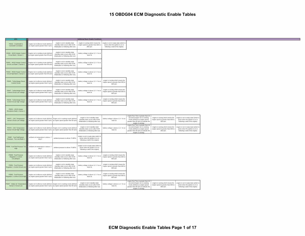
DTC
P0016 - Crankshaft toCamshaft Correlation
engine not in afterrun mode (definedas engine speed greater than 0 rpm)
engine is not in standby state(standby state occurs after ECMinitialization or following after-run)
engine is running which means theengine speed is greater than 600 to
850 rpm
engine is not in ready state (which isactive when the ignition is on orfollowing a stall of the engine)
P0030 - HO2S Heater ControlCircuit Bank 1 Sensor 1
Engine not in cranking mode (definedas engine speed greater than 90 rpm)
engine is not in standby state(standby state occurs after ECMinitialization or following after-run)
battery voltage is above 11 V for atleast 3s
P0031 - HO2S Heater ControlCircuit Low Bank 1 Sensor 1
Engine not in cranking mode (definedas engine speed greater than 90 rpm)
engine is not in standby state(standby state occurs after ECMinitialization or following after-run)
battery voltage is above 11 V for atleast 3s
P0032 - HO2S Heater ControlCircuit High Bank 1 Sensor 1
Engine not in cranking mode (definedas engine speed greater than 90 rpm)
engine is not in standby state(standby state occurs after ECMinitialization or following after-run)
battery voltage is above 11 V for atleast 3s
P0045 - Turbocharger BoostControl Circuit
engine not in afterrun mode (definedas engine speed greater than 0 rpm)
engine is not in standby state(standby state occurs after ECMinitialization or following after-run)
battery voltage is above 11 V for atleast 3s
engine is running which means theengine speed is greater than 600 to
850 rpm
P0047 - Turbocharger BoostControl Circuit Low Voltage
engine not in afterrun mode (definedas engine speed greater than 0 rpm)
engine is not in standby state(standby state occurs after ECMinitialization or following after-run)
battery voltage is above 11 V for atleast 3s
engine is running which means theengine speed is greater than 600 to
850 rpm
P0048 - Turbocharger BoostControl Circuit High Voltage
engine not in afterrun mode (definedas engine speed greater than 0 rpm)
engine is not in standby state(standby state occurs after ECMinitialization or following after-run)
battery voltage is above 11 V for atleast 3s
engine is running which means theengine speed is greater than 600 to
850 rpm
P0053 - HO2S HeaterResistance Bank 1 Sensor 1
P007C - CAC TemperatureSensor Circuit Low Voltage
engine not in afterrun mode (definedas engine speed greater than 0 rpm)
Engine not in cranking mode (definedas engine speed greater than 90 rpm)
engine is not in standby state(standby state occurs after ECMinitialization or following after-run)
battery voltage is above 11 V for atleast 3s
engine Run Time is greater than 10seconds (Engine not in crankingmode (defined as engine speed
greater than 90 rpm) to indicate theengine is running)
engine is running which means theengine speed is greater than 600 to
850 rpm
engine is not in ready state (which isactive when the ignition is on orfollowing a stall of the engine)
P007D - CAC TemperatureSensor Circuit High Voltage
engine not in afterrun mode (definedas engine speed greater than 0 rpm)
Engine not in cranking mode (definedas engine speed greater than 90 rpm)
engine is not in standby state(standby state occurs after ECMinitialization or following after-run)
battery voltage is above 11 V for atleast 3s
engine Run Time is greater than 10seconds (Engine not in crankingmode (defined as engine speed
greater than 90 rpm) to indicate theengine is running)
engine is running which means theengine speed is greater than 600 to
850 rpm
engine is not in ready state (which isactive when the ignition is on orfollowing a stall of the engine)
P0087 - Fuel Rail/SystemPressure - Too Low Bank 1
ambient air temperature is above -7deg C ambient pressure is above 74.8kPa
engine is not in ready state (which isactive when the ignition is on orfollowing a stall of the engine)
P0088 - Fuel Rail Pressure TooHigh
ambient air temperature is above -7deg C ambient pressure is above 74.8kPa
engine is not in ready state (which isactive when the ignition is on orfollowing a stall of the engine)
P0090 - Fuel PressureRegulator 1 Control
Circuit/Open
engine not in afterrun mode (definedas engine speed greater than 0 rpm)
engine is not in standby state(standby state occurs after ECMinitialization or following after-run)
battery voltage is above 11 V for atleast 3s
engine is running which means theengine speed is greater than 600 to
850 rpm
P0091 - Fuel PressureRegulator 1 Control Circuit Low
engine not in afterrun mode (definedas engine speed greater than 0 rpm)
engine is not in standby state(standby state occurs after ECMinitialization or following after-run)
battery voltage is above 11 V for atleast 3s
engine is running which means theengine speed is greater than 600 to
850 rpm
P0092 - Fuel PressureRegulator 1 Control Circuit High
engine not in afterrun mode (definedas engine speed greater than 0 rpm)
engine is not in standby state(standby state occurs after ECMinitialization or following after-run)
battery voltage is above 11 V for atleast 3s
engine is running which means theengine speed is greater than 600 to
850 rpm
P0097 - Intake Air TemperatureSensor 2 Circuit Low
engine not in afterrun mode (definedas engine speed greater than 0 rpm)
Engine not in cranking mode (definedas engine speed greater than 90 rpm)
engine is not in standby state(standby state occurs after ECMinitialization or following after-run)
battery voltage is above 11 V for atleast 3s
engine Run Time is greater than 10seconds (Engine not in crankingmode (defined as engine speed
greater than 90 rpm) to indicate theengine is running)
engine is running which means theengine speed is greater than 600 to
850 rpm
engine is not in ready state (which isactive when the ignition is on orfollowing a stall of the engine)
Additional Basic Enable Conditions
15 OBDG04 ECM Diagnostic Enable Tables
ECM Diagnostic Enable Tables Page 1 of 17

DTC Additional Basic Enable Conditions
P0098 - Intake Air TemperatureSensor 2 Circuit High
engine not in afterrun mode (definedas engine speed greater than 0 rpm)
Engine not in cranking mode (definedas engine speed greater than 90 rpm)
engine is not in standby state(standby state occurs after ECMinitialization or following after-run)
battery voltage is above 11 V for atleast 3s
engine Run Time is greater than 10seconds (Engine not in crankingmode (defined as engine speed
greater than 90 rpm) to indicate theengine is running)
engine is running which means theengine speed is greater than 600 to
850 rpm
engine is not in ready state (which isactive when the ignition is on orfollowing a stall of the engine)
P00C9 - Fuel PressureRegulator Solenoid SupplyVoltage Control Circuit Low
engine not in afterrun mode (definedas engine speed greater than 0 rpm)
engine is not in standby state(standby state occurs after ECMinitialization or following after-run)
battery voltage is above 11 V for atleast 3s
engine is running which means theengine speed is greater than 600 to
850 rpm
P00CA - Fuel PressureRegulator Solenoid SupplyVoltage Control Circuit High
engine not in afterrun mode (definedas engine speed greater than 0 rpm)
engine is not in standby state(standby state occurs after ECMinitialization or following after-run)
battery voltage is above 11 V for atleast 3s
engine is running which means theengine speed is greater than 600 to
850 rpm
P00EA - Intake Air Temperature(IAT) Sensor 3 Circuit Low
Voltage
engine not in afterrun mode (definedas engine speed greater than 0 rpm)
Engine not in cranking mode (definedas engine speed greater than 90 rpm)
engine is not in standby state(standby state occurs after ECMinitialization or following after-run)
battery voltage is above 11 V for atleast 3s
engine Run Time is greater than 10seconds (Engine not in crankingmode (defined as engine speed
greater than 90 rpm) to indicate theengine is running)
engine is running which means theengine speed is greater than 600 to
850 rpm
engine is not in ready state (which isactive when the ignition is on orfollowing a stall of the engine)
P00EB - Intake Air Temperature(IAT) Sensor 3 Circuit High
Voltage
engine not in afterrun mode (definedas engine speed greater than 0 rpm)
Engine not in cranking mode (definedas engine speed greater than 90 rpm)
engine is not in standby state(standby state occurs after ECMinitialization or following after-run)
battery voltage is above 11 V for atleast 3s
engine Run Time is greater than 10seconds (Engine not in crankingmode (defined as engine speed
greater than 90 rpm) to indicate theengine is running)
engine is running which means theengine speed is greater than 600 to
850 rpm
engine is not in ready state (which isactive when the ignition is on orfollowing a stall of the engine)
P00F4 - Humidity Sensor CircuitLow
engine not in afterrun mode (definedas engine speed greater than 0 rpm)
Engine not in cranking mode (definedas engine speed greater than 90 rpm)
engine is not in standby state(standby state occurs after ECMinitialization or following after-run)
battery voltage is above 11 V for atleast 3s
engine Run Time is greater than 10seconds (Engine not in crankingmode (defined as engine speed
greater than 90 rpm) to indicate theengine is running)
engine is running which means theengine speed is greater than 600 to
850 rpm
engine is not in ready state (which isactive when the ignition is on orfollowing a stall of the engine)
P00F5 - Humidity Sensor CircuitHigh
engine not in afterrun mode (definedas engine speed greater than 0 rpm)
Engine not in cranking mode (definedas engine speed greater than 90 rpm)
engine is not in standby state(standby state occurs after ECMinitialization or following after-run)
battery voltage is above 11 V for atleast 3s
engine Run Time is greater than 10seconds (Engine not in crankingmode (defined as engine speed
greater than 90 rpm) to indicate theengine is running)
engine is running which means theengine speed is greater than 600 to
850 rpm
engine is not in ready state (which isactive when the ignition is on orfollowing a stall of the engine)
P00F6 - Humidity Sensor CircuitIntermittent/Erratic
engine not in afterrun mode (definedas engine speed greater than 0 rpm)
Engine not in cranking mode (definedas engine speed greater than 90 rpm)
engine is not in standby state(standby state occurs after ECMinitialization or following after-run)
battery voltage is above 11 V for atleast 3s
engine Run Time is greater than 10seconds (Engine not in crankingmode (defined as engine speed
greater than 90 rpm) to indicate theengine is running)
engine is running which means theengine speed is greater than 600 to
850 rpm
engine is not in ready state (which isactive when the ignition is on orfollowing a stall of the engine)
P0101 - Mass Air Flow SensorPerformance
engine not in afterrun mode (definedas engine speed greater than 0 rpm)
Engine not in cranking mode (definedas engine speed greater than 90 rpm)
engine is not in standby state(standby state occurs after ECMinitialization or following after-run)
battery voltage is above 11 V for atleast 3s
engine Run Time is greater than 10seconds (Engine not in crankingmode (defined as engine speed
greater than 90 rpm) to indicate theengine is running)
engine is running which means theengine speed is greater than 600 to
850 rpm
engine is not in ready state (which isactive when the ignition is on orfollowing a stall of the engine)
P0102 - Mass Air Flow SensorCircuit Low
engine not in afterrun mode (definedas engine speed greater than 0 rpm)
Engine not in cranking mode (definedas engine speed greater than 90 rpm)
engine is not in standby state(standby state occurs after ECMinitialization or following after-run)
battery voltage is above 11 V for atleast 3s
engine Run Time is greater than 10seconds (Engine not in crankingmode (defined as engine speed
greater than 90 rpm) to indicate theengine is running)
engine is running which means theengine speed is greater than 600 to
850 rpm
engine is not in ready state (which isactive when the ignition is on orfollowing a stall of the engine)
P0103 - Mass Air Flow SensorCircuit High
engine not in afterrun mode (definedas engine speed greater than 0 rpm)
Engine not in cranking mode (definedas engine speed greater than 90 rpm)
engine is not in standby state(standby state occurs after ECMinitialization or following after-run)
battery voltage is above 11 V for atleast 3s
engine Run Time is greater than 10seconds (Engine not in crankingmode (defined as engine speed
greater than 90 rpm) to indicate theengine is running)
engine is running which means theengine speed is greater than 600 to
850 rpm
engine is not in ready state (which isactive when the ignition is on orfollowing a stall of the engine)
P0107 - Manifold AbsolutePressure (MAP) Sensor Circuit
Low Voltage
engine not in afterrun mode (definedas engine speed greater than 0 rpm)
Engine not in cranking mode (definedas engine speed greater than 90 rpm)
engine is not in standby state(standby state occurs after ECMinitialization or following after-run)
battery voltage is above 11 V for atleast 3s
engine is running which means theengine speed is greater than 600 to
850 rpm
engine is not in ready state (which isactive when the ignition is on orfollowing a stall of the engine)
P0108 - Manifold AbsolutePressure (MAP) Sensor Circuit
High Voltage
engine not in afterrun mode (definedas engine speed greater than 0 rpm)
Engine not in cranking mode (definedas engine speed greater than 90 rpm)
engine is not in standby state(standby state occurs after ECMinitialization or following after-run)
battery voltage is above 11 V for atleast 3s
engine is running which means theengine speed is greater than 600 to
850 rpm
engine is not in ready state (which isactive when the ignition is on orfollowing a stall of the engine)
P0112 - Intake Air TemperatureSensor 1 Circuit Low
engine not in afterrun mode (definedas engine speed greater than 0 rpm)
Engine not in cranking mode (definedas engine speed greater than 90 rpm)
engine is not in standby state(standby state occurs after ECMinitialization or following after-run)
battery voltage is above 11 V for atleast 3s
engine Run Time is greater than 10seconds (Engine not in crankingmode (defined as engine speed
greater than 90 rpm) to indicate theengine is running)
engine is running which means theengine speed is greater than 600 to
850 rpm
engine is not in ready state (which isactive when the ignition is on orfollowing a stall of the engine)
P0113 - Intake Air TemperatureSensor 1 Circuit High
engine not in afterrun mode (definedas engine speed greater than 0 rpm)
Engine not in cranking mode (definedas engine speed greater than 90 rpm)
engine is not in standby state(standby state occurs after ECMinitialization or following after-run)
battery voltage is above 11 V for atleast 3s
engine Run Time is greater than 10seconds (Engine not in crankingmode (defined as engine speed
greater than 90 rpm) to indicate theengine is running)
engine is running which means theengine speed is greater than 600 to
850 rpm
engine is not in ready state (which isactive when the ignition is on orfollowing a stall of the engine)
P0117 - Engine CoolantTemperature Sensor Circuit
Low
engine is not in standby state(standby state occurs after ECMinitialization or following after-run)
15 OBDG04 ECM Diagnostic Enable Tables
ECM Diagnostic Enable Tables Page 2 of 17

DTC Additional Basic Enable Conditions
P0118 - Engine CoolantTemperature Sensor Circuit
High
engine is not in standby state(standby state occurs after ECMinitialization or following after-run)
P011B - Engine CoolantTemperature/Intake Air
Temperature Correlation
engine not in afterrun mode (definedas engine speed greater than 0 rpm)
Engine not in cranking mode (definedas engine speed greater than 90 rpm)
engine is not in standby state(standby state occurs after ECMinitialization or following after-run)
engine is running which means theengine speed is greater than 600 to
850 rpm
P0128 - Engine CoolantTemperature Below Thermostat
Regulating Temperature
engine not in afterrun mode (definedas engine speed greater than 0 rpm)
Engine not in cranking mode (definedas engine speed greater than 90 rpm)
engine is not in standby state(standby state occurs after ECMinitialization or following after-run)
engine is running which means theengine speed is greater than 600 to
850 rpm
engine is not in ready state (which isactive when the ignition is on orfollowing a stall of the engine)
P0131 - HO2S Bank 1 Sensor 1circuit low
Engine not in cranking mode (definedas engine speed greater than 90 rpm)
engine is not in standby state(standby state occurs after ECMinitialization or following after-run)
P0132 - HO2S Bank 1 Sensor 1circuit high
Engine not in cranking mode (definedas engine speed greater than 90 rpm)
engine is not in standby state(standby state occurs after ECMinitialization or following after-run)
P0133 - O2 Sensor Circuit SlowResponse Bank 1 Sensor 1
engine not in afterrun mode (definedas engine speed greater than 0 rpm)
Engine not in cranking mode (definedas engine speed greater than 90 rpm)
engine is not in standby state(standby state occurs after ECMinitialization or following after-run)
battery voltage is above 11 V for atleast 3s
engine Run Time is greater than 10seconds (Engine not in crankingmode (defined as engine speed
greater than 90 rpm) to indicate theengine is running)
engine is running which means theengine speed is greater than 600 to
850 rpm
engine is not in ready state (which isactive when the ignition is on orfollowing a stall of the engine)
P0171 - System Too Lean Bank1
System is not in active regenerationmode
P0172 - System Too Rich Bank1
System is not in active regenerationmode
P0182 - Fuel TemperatureSensor 1 Circuit Low
engine not in afterrun mode (definedas engine speed greater than 0 rpm)
Engine not in cranking mode (definedas engine speed greater than 90 rpm)
engine is not in standby state(standby state occurs after ECMinitialization or following after-run)
battery voltage is above 11 V for atleast 3s
engine Run Time is greater than 10seconds (Engine not in crankingmode (defined as engine speed
greater than 90 rpm) to indicate theengine is running)
engine is running which means theengine speed is greater than 600 to
850 rpm
engine is not in ready state (which isactive when the ignition is on orfollowing a stall of the engine)
P0183 - Fuel TemperatureSensor 1 Circuit High
engine not in afterrun mode (definedas engine speed greater than 0 rpm)
Engine not in cranking mode (definedas engine speed greater than 90 rpm)
engine is not in standby state(standby state occurs after ECMinitialization or following after-run)
battery voltage is above 11 V for atleast 3s
engine Run Time is greater than 10seconds (Engine not in crankingmode (defined as engine speed
greater than 90 rpm) to indicate theengine is running)
engine is running which means theengine speed is greater than 600 to
850 rpm
engine is not in ready state (which isactive when the ignition is on orfollowing a stall of the engine)
P0191 - Fuel Rail PressureSensor Performance
engine is not in standby state(standby state occurs after ECMinitialization or following after-run)
battery voltage is above 11 V for atleast 3s
P0192 - Fuel Rail PressureSensor Circuit Low
engine is not in standby state(standby state occurs after ECMinitialization or following after-run)
battery voltage is above 11 V for atleast 3s
P0193 - Fuel Rail PressureSensor Circuit High
engine is not in standby state(standby state occurs after ECMinitialization or following after-run)
battery voltage is above 11 V for atleast 3s
P01CB - Cylinder 1 InjectionTiming Retarded
ambient air temperature is above -7deg C ambient pressure is above 74.8kPa
engine is not in ready state (which isactive when the ignition is on orfollowing a stall of the engine)
P01CC - Cylinder 1 InjectionTiming Advanced
ambient air temperature is above -7deg C ambient pressure is above 74.8kPa
engine is not in ready state (which isactive when the ignition is on orfollowing a stall of the engine)
P01CD - Cylinder 2 InjectionTiming Retarded
ambient air temperature is above -7deg C ambient pressure is above 74.8kPa
engine is not in ready state (which isactive when the ignition is on orfollowing a stall of the engine)
15 OBDG04 ECM Diagnostic Enable Tables
ECM Diagnostic Enable Tables Page 3 of 17

DTC Additional Basic Enable Conditions
P01CE - Cylinder 2 InjectionTiming Advanced
ambient air temperature is above -7deg C ambient pressure is above 74.8kPa
engine is not in ready state (which isactive when the ignition is on orfollowing a stall of the engine)
P01CF - Cylinder 3 InjectionTiming Retarded
ambient air temperature is above -7deg C ambient pressure is above 74.8kPa
engine is not in ready state (which isactive when the ignition is on orfollowing a stall of the engine)
P01D0 - Cylinder 3 InjectionTiming Advanced
ambient air temperature is above -7deg C ambient pressure is above 74.8kPa
engine is not in ready state (which isactive when the ignition is on orfollowing a stall of the engine)
P01D1 - Cylinder 4 InjectionTiming Retarded
ambient air temperature is above -7deg C ambient pressure is above 74.8kPa
engine is not in ready state (which isactive when the ignition is on orfollowing a stall of the engine)
P01D2 - Cylinder 4 InjectionTiming Advanced
ambient air temperature is above -7deg C ambient pressure is above 74.8kPa
engine is not in ready state (which isactive when the ignition is on orfollowing a stall of the engine)
P01F0 - Coolant TemperatureDropped Below Diagnostic
Monitoring Temperature
engine not in afterrun mode (definedas engine speed greater than 0 rpm)
Engine not in cranking mode (definedas engine speed greater than 90 rpm)
engine is not in standby state(standby state occurs after ECMinitialization or following after-run)
engine is running which means theengine speed is greater than 600 to
850 rpm
engine is not in ready state (which isactive when the ignition is on orfollowing a stall of the engine)
P0234 - Turbocharger EngineOverboost
engine not in afterrun mode (definedas engine speed greater than 0 rpm)
Engine not in cranking mode (definedas engine speed greater than 90 rpm)
engine is not in standby state(standby state occurs after ECMinitialization or following after-run)
ambient air temperature is above -7deg C ambient pressure is above 74.8kPa battery voltage is above 11 V for at
least 3s
engine Run Time is greater than 10seconds (Engine not in crankingmode (defined as engine speed
greater than 90 rpm) to indicate theengine is running)
engine is running which means theengine speed is greater than 600 to
850 rpm
engine is not in ready state (which isactive when the ignition is on orfollowing a stall of the engine)
P026A - CAC EffiecientcyBelow Threshold
engine not in afterrun mode (definedas engine speed greater than 0 rpm)
Engine not in cranking mode (definedas engine speed greater than 90 rpm)
engine is not in standby state(standby state occurs after ECMinitialization or following after-run)
ambient air temperature is above -7deg C ambient pressure is above 74.8kPa battery voltage is above 11 V for at
least 3s
engine Run Time is greater than 10seconds (Engine not in crankingmode (defined as engine speed
greater than 90 rpm) to indicate theengine is running)
engine is running which means theengine speed is greater than 600 to
850 rpm
engine is not in ready state (which isactive when the ignition is on orfollowing a stall of the engine)
P026C - Injection Quantity TooLow
ambient air temperature is above -7deg C ambient pressure is above 74.8kPa System is not in active regeneration
mode
P026D - Injection Quantity TooHigh
ambient air temperature is above -7deg C ambient pressure is above 74.8kPa System is not in active regeneration
mode
P0299 - Turbocharger EngineUnderboost
engine not in afterrun mode (definedas engine speed greater than 0 rpm)
Engine not in cranking mode (definedas engine speed greater than 90 rpm)
engine is not in standby state(standby state occurs after ECMinitialization or following after-run)
ambient air temperature is above -7deg C ambient pressure is above 74.8kPa battery voltage is above 11 V for at
least 3s
engine Run Time is greater than 10seconds (Engine not in crankingmode (defined as engine speed
greater than 90 rpm) to indicate theengine is running)
engine is running which means theengine speed is greater than 600 to
850 rpm
engine is not in ready state (which isactive when the ignition is on orfollowing a stall of the engine)
P02E2 - Intake Air Flow ValveControl Circuit 1 Low Voltage
engine is not in standby state(standby state occurs after ECMinitialization or following after-run)
battery voltage is above 11 V for atleast 3s
P02E3 - Intake Air Flow ValveControl Circuit 1 High Voltage
engine is not in standby state(standby state occurs after ECMinitialization or following after-run)
battery voltage is above 11 V for atleast 3s
P02E7 - Diesel Intake Air FlowPosition Sensor Circuit Range
Performance
engine not in afterrun mode (definedas engine speed greater than 0 rpm)
Engine not in cranking mode (definedas engine speed greater than 90 rpm)
engine is not in standby state(standby state occurs after ECMinitialization or following after-run)
battery voltage is above 11 V for atleast 3s
engine Run Time is greater than 10seconds (Engine not in crankingmode (defined as engine speed
greater than 90 rpm) to indicate theengine is running)
engine is running which means theengine speed is greater than 600 to
850 rpm
engine is not in ready state (which isactive when the ignition is on orfollowing a stall of the engine)
P02E8 - Diesel Intake Air FlowPosition Sensor Circuit Low
engine not in afterrun mode (definedas engine speed greater than 0 rpm)
Engine not in cranking mode (definedas engine speed greater than 90 rpm)
engine is not in standby state(standby state occurs after ECMinitialization or following after-run)
battery voltage is above 11 V for atleast 3s
engine Run Time is greater than 10seconds (Engine not in crankingmode (defined as engine speed
greater than 90 rpm) to indicate theengine is running)
engine is running which means theengine speed is greater than 600 to
850 rpm
engine is not in ready state (which isactive when the ignition is on orfollowing a stall of the engine)
P02E9 - Diesel Intake Air FlowPosition Sensor Circuit High
engine not in afterrun mode (definedas engine speed greater than 0 rpm)
Engine not in cranking mode (definedas engine speed greater than 90 rpm)
engine is not in standby state(standby state occurs after ECMinitialization or following after-run)
battery voltage is above 11 V for atleast 3s
engine Run Time is greater than 10seconds (Engine not in crankingmode (defined as engine speed
greater than 90 rpm) to indicate theengine is running)
engine is running which means theengine speed is greater than 600 to
850 rpm
engine is not in ready state (which isactive when the ignition is on orfollowing a stall of the engine)
15 OBDG04 ECM Diagnostic Enable Tables
ECM Diagnostic Enable Tables Page 4 of 17

DTC Additional Basic Enable Conditions
P02EB - Intake Air Flow ValveControl Motor Current
Performance
engine is not in standby state(standby state occurs after ECMinitialization or following after-run)
battery voltage is above 11 V for atleast 3s
P0300 - Engine MisfireDetected
engine is not in ready state (which isactive when the ignition is on orfollowing a stall of the engine)
P0301 - Cylinder 1 MisfireDetected
engine is not in ready state (which isactive when the ignition is on orfollowing a stall of the engine)
P0302 - Cylinder 2 MisfireDetected
engine is not in ready state (which isactive when the ignition is on orfollowing a stall of the engine)
P0303 - Cylinder 3 MisfireDetected
engine is not in ready state (which isactive when the ignition is on orfollowing a stall of the engine)
P0304 - Cylinder 4 MisfireDetected
engine is not in ready state (which isactive when the ignition is on orfollowing a stall of the engine)
P0335 - Crankshaft PositionSensor Circuit
engine not in afterrun mode (definedas engine speed greater than 0 rpm)
engine is not in standby state(standby state occurs after ECMinitialization or following after-run)
engine is running which means theengine speed is greater than 600 to
850 rpm
battery voltage is above 11 V for atleast 3s
P0336 - Crankshaft PositionSensor Performance
engine not in afterrun mode (definedas engine speed greater than 0 rpm)
engine is not in standby state(standby state occurs after ECMinitialization or following after-run)
engine is running which means theengine speed is greater than 600 to
850 rpm
P0340 - Camshaft PositionSensor Circuit
engine not in afterrun mode (definedas engine speed greater than 0 rpm)
engine is not in standby state(standby state occurs after ECMinitialization or following after-run)
engine is running which means theengine speed is greater than 600 to
850 rpm
P0341 - Camshaft PositionSensor Performance
engine not in afterrun mode (definedas engine speed greater than 0 rpm)
engine is not in standby state(standby state occurs after ECMinitialization or following after-run)
engine is running which means theengine speed is greater than 600 to
850 rpm
P037A - Glow Plug/HeaterIndicator Control Circuit Low
engine not in afterrun mode (definedas engine speed greater than 0 rpm)
engine is not in standby state(standby state occurs after ECMinitialization or following after-run)
battery voltage is above 11 V for atleast 3s
engine is running which means theengine speed is greater than 600 to
850 rpm
P037B - Glow Plug/HeaterIndicator Control Circuit High
engine not in afterrun mode (definedas engine speed greater than 0 rpm)
engine is not in standby state(standby state occurs after ECMinitialization or following after-run)
battery voltage is above 11 V for atleast 3s
engine is running which means theengine speed is greater than 600 to
850 rpm
P0401 - Exhaust GasRecirculation Flow Insufficient
engine not in afterrun mode (definedas engine speed greater than 0 rpm)
Engine not in cranking mode (definedas engine speed greater than 90 rpm)
engine is not in standby state(standby state occurs after ECMinitialization or following after-run)
ambient air temperature is above -7deg C ambient pressure is above 74.8kPa battery voltage is above 11 V for at
least 3s
engine Run Time is greater than 10seconds (Engine not in crankingmode (defined as engine speed
greater than 90 rpm) to indicate theengine is running)
System is not in active regenerationmode
engine is running which means theengine speed is greater than 600 to
850 rpm
engine is not in ready state (which isactive when the ignition is on or following
a stall of the engine)
P0402 - Exhaust GasRecirculation Flow Excessive
engine not in afterrun mode (definedas engine speed greater than 0 rpm)
Engine not in cranking mode (definedas engine speed greater than 90 rpm)
engine is not in standby state(standby state occurs after ECMinitialization or following after-run)
ambient air temperature is above -7deg C ambient pressure is above 74.8kPa battery voltage is above 11 V for at
least 3s
engine Run Time is greater than 10seconds (Engine not in crankingmode (defined as engine speed
greater than 90 rpm) to indicate theengine is running)
System is not in active regenerationmode
engine is running which means theengine speed is greater than 600 to
850 rpm
engine is not in ready state (which isactive when the ignition is on or following
a stall of the engine)
P0405 - Exhaust GasRecirculation Position Sensor
Circuit Low
engine not in afterrun mode (definedas engine speed greater than 0 rpm)
Engine not in cranking mode (definedas engine speed greater than 90 rpm)
engine is not in standby state(standby state occurs after ECMinitialization or following after-run)
battery voltage is above 11 V for atleast 3s
engine Run Time is greater than 10seconds (Engine not in crankingmode (defined as engine speed
greater than 90 rpm) to indicate theengine is running)
engine is running which means theengine speed is greater than 600 to
850 rpm
engine is not in ready state (which isactive when the ignition is on orfollowing a stall of the engine)
P0406 - Exhaust GasRecirculation Position Sensor
Circuit High
engine not in afterrun mode (definedas engine speed greater than 0 rpm)
Engine not in cranking mode (definedas engine speed greater than 90 rpm)
engine is not in standby state(standby state occurs after ECMinitialization or following after-run)
battery voltage is above 11 V for atleast 3s
engine Run Time is greater than 10seconds (Engine not in crankingmode (defined as engine speed
greater than 90 rpm) to indicate theengine is running)
engine is running which means theengine speed is greater than 600 to
850 rpm
engine is not in ready state (which isactive when the ignition is on orfollowing a stall of the engine)
15 OBDG04 ECM Diagnostic Enable Tables
ECM Diagnostic Enable Tables Page 5 of 17

DTC Additional Basic Enable Conditions
P040C - Exhaust GasRecirculation (EGR)
Temperature Sensor 2 CircuitLow Voltage
engine not in afterrun mode (definedas engine speed greater than 0 rpm)
Engine not in cranking mode (definedas engine speed greater than 90 rpm)
engine is not in standby state(standby state occurs after ECMinitialization or following after-run)
battery voltage is above 11 V for atleast 3s
engine Run Time is greater than 10seconds (Engine not in crankingmode (defined as engine speed
greater than 90 rpm) to indicate theengine is running)
engine is running which means theengine speed is greater than 600 to
850 rpm
engine is not in ready state (which isactive when the ignition is on orfollowing a stall of the engine)
P040D - Exhaust GasRecirculation (EGR)
Temperature Sensor 2 CircuitHigh Voltage
engine not in afterrun mode (definedas engine speed greater than 0 rpm)
Engine not in cranking mode (definedas engine speed greater than 90 rpm)
engine is not in standby state(standby state occurs after ECMinitialization or following after-run)
battery voltage is above 11 V for atleast 3s
engine Run Time is greater than 10seconds (Engine not in crankingmode (defined as engine speed
greater than 90 rpm) to indicate theengine is running)
engine is running which means theengine speed is greater than 600 to
850 rpm
engine is not in ready state (which isactive when the ignition is on orfollowing a stall of the engine)
P040F - Exhaust GasRecirculation (EGR)
Temperature Sensor 1-2Correlation
engine not in afterrun mode (definedas engine speed greater than 0 rpm)
Engine not in cranking mode (definedas engine speed greater than 90 rpm)
engine is not in standby state(standby state occurs after ECMinitialization or following after-run)
engine is running which means theengine speed is greater than 600 to
850 rpm
engine is not in ready state (which isactive when the ignition is on orfollowing a stall of the engine)
P041C - Exhaust GasRecirculation (EGR)
Temperature Sensor 1 CircuitLow Voltage
engine not in afterrun mode (definedas engine speed greater than 0 rpm)
Engine not in cranking mode (definedas engine speed greater than 90 rpm)
engine is not in standby state(standby state occurs after ECMinitialization or following after-run)
battery voltage is above 11 V for atleast 3s
engine Run Time is greater than 10seconds (Engine not in crankingmode (defined as engine speed
greater than 90 rpm) to indicate theengine is running)
engine is running which means theengine speed is greater than 600 to
850 rpm
engine is not in ready state (which isactive when the ignition is on orfollowing a stall of the engine)
P041D - Exhaust GasRecirculation (EGR)
Temperature Sensor 1 CircuitHigh Voltage
engine not in afterrun mode (definedas engine speed greater than 0 rpm)
Engine not in cranking mode (definedas engine speed greater than 90 rpm)
engine is not in standby state(standby state occurs after ECMinitialization or following after-run)
battery voltage is above 11 V for atleast 3s
engine Run Time is greater than 10seconds (Engine not in crankingmode (defined as engine speed
greater than 90 rpm) to indicate theengine is running)
engine is running which means theengine speed is greater than 600 to
850 rpm
engine is not in ready state (which isactive when the ignition is on orfollowing a stall of the engine)
P0420 - NMHC CatalystEfficiency Below Threshold
Bank 1
engine not in afterrun mode (definedas engine speed greater than 0 rpm)
Engine not in cranking mode (definedas engine speed greater than 90 rpm)
engine is not in standby state(standby state occurs after ECMinitialization or following after-run)
Manufacturer Enable Counter is zero(value of 0 means ECM is locked and
out of assembly plant mode)
ambient air temperature is above -7deg C ambient pressure is above 74.8kPa battery voltage is above 11 V for at
least 3s
engine Run Time is greater than 10seconds (Engine not in crankingmode (defined as engine speed
greater than 90 rpm) to indicate theengine is running)
engine is running which means theengine speed is greater than 600 to
850 rpm
engine is not in ready state (which isactive when the ignition is on or following
a stall of the engine)
P0461 - Fuel Level SensorPerformance
engine not in afterrun mode (definedas engine speed greater than 0 rpm)
Engine not in cranking mode (definedas engine speed greater than 90 rpm)
engine is not in standby state(standby state occurs after ECMinitialization or following after-run)
battery voltage is above 11 V for atleast 3s
engine Run Time is greater than 10seconds (Engine not in crankingmode (defined as engine speed
greater than 90 rpm) to indicate theengine is running)
engine is running which means theengine speed is greater than 600 to
850 rpm
engine is not in ready state (which isactive when the ignition is on orfollowing a stall of the engine)
P0462 - Fuel Level SensorCircuit Low
engine not in afterrun mode (definedas engine speed greater than 0 rpm)
Engine not in cranking mode (definedas engine speed greater than 90 rpm)
engine is not in standby state(standby state occurs after ECMinitialization or following after-run)
battery voltage is above 11 V for atleast 3s
engine Run Time is greater than 10seconds (Engine not in crankingmode (defined as engine speed
greater than 90 rpm) to indicate theengine is running)
engine is running which means theengine speed is greater than 600 to
850 rpm
engine is not in ready state (which isactive when the ignition is on orfollowing a stall of the engine)
P0463 - Fuel Level SensorCircuit High
engine not in afterrun mode (definedas engine speed greater than 0 rpm)
Engine not in cranking mode (definedas engine speed greater than 90 rpm)
engine is not in standby state(standby state occurs after ECMinitialization or following after-run)
battery voltage is above 11 V for atleast 3s
engine Run Time is greater than 10seconds (Engine not in crankingmode (defined as engine speed
greater than 90 rpm) to indicate theengine is running)
engine is running which means theengine speed is greater than 600 to
850 rpm
engine is not in ready state (which isactive when the ignition is on orfollowing a stall of the engine)
P0489 - Exhaust GasRecirculation (EGR) Motor
Control Circuit 1 Low Voltage
engine is not in standby state(standby state occurs after ECMinitialization or following after-run)
battery voltage is above 11 V for atleast 3s
P0490 - Exhaust GasRecirculation (EGR) Motor
Control Circuit 1 High Voltage
engine is not in standby state(standby state occurs after ECMinitialization or following after-run)
battery voltage is above 11 V for atleast 3s
P0506 - Idle Speed Low
engine Run Time is greater than 10seconds (Engine not in crankingmode (defined as engine speed
greater than 90 rpm) to indicate theengine is running)
engine is not in ready state (which isactive when the ignition is on orfollowing a stall of the engine)
P0507 - Idle Speed High
engine Run Time is greater than 10seconds (Engine not in crankingmode (defined as engine speed
greater than 90 rpm) to indicate theengine is running)
engine is not in ready state (which isactive when the ignition is on orfollowing a stall of the engine)
P0545 - Exhaust GasTemperature (EGT) Sensor 1
Circuit Low Voltage
engine not in afterrun mode (definedas engine speed greater than 0 rpm)
Engine not in cranking mode (definedas engine speed greater than 90 rpm)
engine is not in standby state(standby state occurs after ECMinitialization or following after-run)
battery voltage is above 11 V for atleast 3s
engine is running which means theengine speed is greater than 600 to
850 rpm
P0546 - Exhaust GasTemperature (EGT) Sensor 1
Circuit High Voltage
engine not in afterrun mode (definedas engine speed greater than 0 rpm)
Engine not in cranking mode (definedas engine speed greater than 90 rpm)
engine is not in standby state(standby state occurs after ECMinitialization or following after-run)
battery voltage is above 11 V for atleast 3s
engine is running which means theengine speed is greater than 600 to
850 rpm
P054E - Idle Control System -Fuel Quantity Lower Than
Expected
engine not in afterrun mode (definedas engine speed greater than 0 rpm)
Engine not in cranking mode (definedas engine speed greater than 90 rpm)
engine is not in standby state(standby state occurs after ECMinitialization or following after-run)
ambient air temperature is above -7deg C
engine is running which means theengine speed is greater than 600 to
850 rpm
engine is not in ready state (which isactive when the ignition is on orfollowing a stall of the engine)
15 OBDG04 ECM Diagnostic Enable Tables
ECM Diagnostic Enable Tables Page 6 of 17

DTC Additional Basic Enable Conditions
P054F - Idle Control System -Fuel Quantity Higher Than
Expected
engine not in afterrun mode (definedas engine speed greater than 0 rpm)
Engine not in cranking mode (definedas engine speed greater than 90 rpm)
engine is not in standby state(standby state occurs after ECMinitialization or following after-run)
ambient air temperature is above -7deg C
engine is running which means theengine speed is greater than 600 to
850 rpm
engine is not in ready state (which isactive when the ignition is on orfollowing a stall of the engine)
P0564 - Cruise Control Multi-Function Input "A" Circuit
engine not in afterrun mode (definedas engine speed greater than 0 rpm)
Engine not in cranking mode (definedas engine speed greater than 90 rpm)
engine is not in standby state(standby state occurs after ECMinitialization or following after-run)
Manufacturer Enable Counter is zero(value of 0 means ECM is locked and
out of assembly plant mode)
battery voltage is above 11 V for atleast 3s
engine Run Time is greater than 10seconds (Engine not in crankingmode (defined as engine speed
greater than 90 rpm) to indicate theengine is running)
engine is running which means theengine speed is greater than 600 to
850 rpm
engine is not in ready state (which isactive when the ignition is on orfollowing a stall of the engine)
P0567 - Cruise Control ResumeSwitch Circuit
engine not in afterrun mode (definedas engine speed greater than 0 rpm)
Engine not in cranking mode (definedas engine speed greater than 90 rpm)
engine is not in standby state(standby state occurs after ECMinitialization or following after-run)
Manufacturer Enable Counter is zero(value of 0 means ECM is locked and
out of assembly plant mode)
battery voltage is above 11 V for atleast 3s
engine Run Time is greater than 10seconds (Engine not in crankingmode (defined as engine speed
greater than 90 rpm) to indicate theengine is running)
engine is running which means theengine speed is greater than 600 to
850 rpm
engine is not in ready state (which isactive when the ignition is on orfollowing a stall of the engine)
P0568 - Cruise Control SetSwitch Circuit
engine not in afterrun mode (definedas engine speed greater than 0 rpm)
Engine not in cranking mode (definedas engine speed greater than 90 rpm)
engine is not in standby state(standby state occurs after ECMinitialization or following after-run)
Manufacturer Enable Counter is zero(value of 0 means ECM is locked and
out of assembly plant mode)
battery voltage is above 11 V for atleast 3s
engine Run Time is greater than 10seconds (Engine not in crankingmode (defined as engine speed
greater than 90 rpm) to indicate theengine is running)
engine is running which means theengine speed is greater than 600 to
850 rpm
engine is not in ready state (which isactive when the ignition is on orfollowing a stall of the engine)
P0575 - Cruise Control InputCircuit
engine not in afterrun mode (definedas engine speed greater than 0 rpm)
Engine not in cranking mode (definedas engine speed greater than 90 rpm)
engine is not in standby state(standby state occurs after ECMinitialization or following after-run)
Manufacturer Enable Counter is zero(value of 0 means ECM is locked and
out of assembly plant mode)
battery voltage is above 11 V for atleast 3s
engine is running which means theengine speed is greater than 600 to
850 rpm
engine is not in ready state (which isactive when the ignition is on orfollowing a stall of the engine)
P057C - Brake Pedal PositionSensor Circuit High Voltage
engine is not in standby state(standby state occurs after ECMinitialization or following after-run)
P057D - Brake Pedal PositionSensor Circuit Low Voltage
engine is not in standby state(standby state occurs after ECMinitialization or following after-run)
P0627 - Fuel Pump RelayControl Circuit
engine not in afterrun mode (definedas engine speed greater than 0 rpm)
battery voltage is above 11 V for atleast 3s
engine is running which means theengine speed is greater than 600 to
850 rpm
P0628 - Fuel Pump RelayControl Circuit Low
engine not in afterrun mode (definedas engine speed greater than 0 rpm)
battery voltage is above 11 V for atleast 3s
engine is running which means theengine speed is greater than 600 to
850 rpm
P0629 - Fuel Pump RelayControl Circuit High
battery voltage is above 11 V for atleast 3s
P064C - Glow Plug ControlModule Performance
engine is not in standby state(standby state occurs after ECMinitialization or following after-run)
battery voltage is above 11 V for atleast 3s
P0671 - Glow Plug 1 ControlCircuit
engine is not in standby state(standby state occurs after ECMinitialization or following after-run)
battery voltage is above 11 V for atleast 3s
P0672 - Glow Plug 2 ControlCircuit
engine is not in standby state(standby state occurs after ECMinitialization or following after-run)
battery voltage is above 11 V for atleast 3s
P0673 - Glow Plug 3 ControlCircuit
engine is not in standby state(standby state occurs after ECMinitialization or following after-run)
battery voltage is above 11 V for atleast 3s
P0674 - Glow Plug 4 ControlCircuit
engine is not in standby state(standby state occurs after ECMinitialization or following after-run)
battery voltage is above 11 V for atleast 3s
P0691 - Fan 1 Control CircuitLow
battery voltage is above 11 V for atleast 3s
15 OBDG04 ECM Diagnostic Enable Tables
ECM Diagnostic Enable Tables Page 7 of 17

DTC Additional Basic Enable Conditions
P0692 - Fan 1 Control CircuitHigh
battery voltage is above 11 V for atleast 3s
P069E - Fuel Pump ControlModule Requested MIL
Illumination
engine is not in standby state(standby state occurs after ECMinitialization or following after-run)
P0700 - Transmission ControlModule Requested Malfunction
Indicator Lamp Illumination
engine is not in standby state(standby state occurs after ECMinitialization or following after-run)
P0851 - Park/Neutral Position(PNP) Switch Circuit Low
Voltage
engine is not in standby state(standby state occurs after ECMinitialization or following after-run)
P0852 - Park/Neutral Position(PNP) Switch Circuit High
Voltage
engine is not in standby state(standby state occurs after ECMinitialization or following after-run)
P1043 - Reductant Pump HighControl Circuit Low Voltage
engine not in afterrun mode (definedas engine speed greater than 0 rpm)
Engine not in cranking mode (definedas engine speed greater than 90 rpm)
engine is not in standby state(standby state occurs after ECMinitialization or following after-run)
engine Run Time is greater than 10seconds (Engine not in crankingmode (defined as engine speed
greater than 90 rpm) to indicate theengine is running)
engine is running which means theengine speed is greater than 600 to
850 rpm
engine is not in ready state (which isactive when the ignition is on orfollowing a stall of the engine)
P1046 - Reductant Purge ValveHigh Control Circuit High
Voltage
engine not in afterrun mode (definedas engine speed greater than 0 rpm)
Engine not in cranking mode (definedas engine speed greater than 90 rpm)
engine is not in standby state(standby state occurs after ECMinitialization or following after-run)
engine Run Time is greater than 10seconds (Engine not in crankingmode (defined as engine speed
greater than 90 rpm) to indicate theengine is running)
engine is running which means theengine speed is greater than 600 to
850 rpm
engine is not in ready state (which isactive when the ignition is on orfollowing a stall of the engine)
P1048 - Reductant Injector HighControl Circuit Low Voltage
engine not in afterrun mode (definedas engine speed greater than 0 rpm)
Engine not in cranking mode (definedas engine speed greater than 90 rpm)
engine is not in standby state(standby state occurs after ECMinitialization or following after-run)
battery voltage is above 11 V for atleast 3s
engine Run Time is greater than 10seconds (Engine not in crankingmode (defined as engine speed
greater than 90 rpm) to indicate theengine is running)
engine is running which means theengine speed is greater than 600 to
850 rpm
engine is not in ready state (which isactive when the ignition is on orfollowing a stall of the engine)
P1049 - Reductant Injector HighControl Circuit High Voltage
engine not in afterrun mode (definedas engine speed greater than 0 rpm)
Engine not in cranking mode (definedas engine speed greater than 90 rpm)
engine is not in standby state(standby state occurs after ECMinitialization or following after-run)
battery voltage is above 11 V for atleast 3s
engine Run Time is greater than 10seconds (Engine not in crankingmode (defined as engine speed
greater than 90 rpm) to indicate theengine is running)
engine is running which means theengine speed is greater than 600 to
850 rpm
engine is not in ready state (which isactive when the ignition is on orfollowing a stall of the engine)
P10CF - Charge Air CoolerTemperature - Intake Air
Temperature (IAT) Sensor 3Correlation
engine not in afterrun mode (definedas engine speed greater than 0 rpm)
Engine not in cranking mode (definedas engine speed greater than 90 rpm)
engine is not in standby state(standby state occurs after ECMinitialization or following after-run)
engine is running which means theengine speed is greater than 600 to
850 rpm
engine is not in ready state (which isactive when the ignition is on orfollowing a stall of the engine)
P10D0 - Reductant InjectorTemperature - Exhaust GasTemperature 2 Correlation
engine not in afterrun mode (definedas engine speed greater than 0 rpm)
engine is running which means theengine speed is greater than 600 to
850 rpm
P11A6 - HO2S Performance -Signal High During Moderate
Load Sensor 1
engine not in afterrun mode (definedas engine speed greater than 0 rpm)
Engine not in cranking mode (definedas engine speed greater than 90 rpm)
engine is not in standby state(standby state occurs after ECMinitialization or following after-run)
battery voltage is above 11 V for atleast 3s
engine Run Time is greater than 10seconds (Engine not in crankingmode (defined as engine speed
greater than 90 rpm) to indicate theengine is running)
engine is running which means theengine speed is greater than 600 to
850 rpm
engine is not in ready state (which isactive when the ignition is on orfollowing a stall of the engine)
P11A9 - O2 SensorPerformance - Signal Low
During Moderate Load Bank 1Sensor 1
engine not in afterrun mode (definedas engine speed greater than 0 rpm)
Engine not in cranking mode (definedas engine speed greater than 90 rpm)
engine is not in standby state(standby state occurs after ECMinitialization or following after-run)
battery voltage is above 11 V for atleast 3s
engine Run Time is greater than 10seconds (Engine not in crankingmode (defined as engine speed
greater than 90 rpm) to indicate theengine is running)
engine is running which means theengine speed is greater than 600 to
850 rpm
engine is not in ready state (which isactive when the ignition is on orfollowing a stall of the engine)
P11CB - NOx SensorPerformance - Signal High Bank
1 Sensor 1
engine not in afterrun mode (definedas engine speed greater than 0 rpm)
Engine not in cranking mode (definedas engine speed greater than 90 rpm)
engine is not in standby state(standby state occurs after ECMinitialization or following after-run)
Manufacturer Enable Counter is zero(value of 0 means ECM is locked and
out of assembly plant mode)
ambient air temperature is above -7deg C ambient pressure is above 74.8kPa battery voltage is above 11 V for at
least 3s
engine Run Time is greater than 10seconds (Engine not in crankingmode (defined as engine speed
greater than 90 rpm) to indicate theengine is running)
System is not in active regenerationmode
engine is running which means theengine speed is greater than 600 to 850
rpm
engine is not in ready state (which isactive when the ignition is on orfollowing a stall of the engine)
P11CC - NOx SensorPerformance - Signal Low Bank
1 Sensor 1
engine not in afterrun mode (definedas engine speed greater than 0 rpm)
Engine not in cranking mode (definedas engine speed greater than 90 rpm)
engine is not in standby state(standby state occurs after ECMinitialization or following after-run)
Manufacturer Enable Counter is zero(value of 0 means ECM is locked and
out of assembly plant mode)
ambient air temperature is above -7deg C ambient pressure is above 74.8kPa battery voltage is above 11 V for at
least 3s
engine Run Time is greater than 10seconds (Engine not in crankingmode (defined as engine speed
greater than 90 rpm) to indicate theengine is running)
System is not in active regenerationmode
engine is running which means theengine speed is greater than 600 to 850
rpm
engine is not in ready state (which isactive when the ignition is on orfollowing a stall of the engine)
P11D3 - Nox Sensor OffsetLearning at Min Limit - Bank 1
Sensor 1
battery voltage is above 11 V for atleast 3s
15 OBDG04 ECM Diagnostic Enable Tables
ECM Diagnostic Enable Tables Page 8 of 17

DTC Additional Basic Enable Conditions
P11D4 - Nox Sensor OffsetLearning at Max Limit - Bank 1
Sensor 1
battery voltage is above 11 V for atleast 3s
P11D7 - Nox SensorPerformance - Sensing ElementStatus Signal Bank 1 Sensor 2
Manufacturer Enable Counter is zero(value of 0 means ECM is locked and
out of assembly plant mode)
ambient air temperature is above -7deg C ambient pressure is above 74.8kPa battery voltage is above 11 V for at
least 3s
engine Run Time is greater than 10seconds (Engine not in crankingmode (defined as engine speed
greater than 90 rpm) to indicate theengine is running)
System is not in active regenerationmode
P11DB - NOx Sensor CurrentPerformance Bank 1 Sensor 1
engine not in afterrun mode (definedas engine speed greater than 0 rpm)
Engine not in cranking mode (definedas engine speed greater than 90 rpm)
engine is not in standby state(standby state occurs after ECMinitialization or following after-run)
Manufacturer Enable Counter is zero(value of 0 means ECM is locked and
out of assembly plant mode)
battery voltage is above 11 V for atleast 3s
engine Run Time is greater than 10seconds (Engine not in crankingmode (defined as engine speed
greater than 90 rpm) to indicate theengine is running)
System is not in active regenerationmode
engine is running which means theengine speed is greater than 600 to
850 rpm
engine is not in ready state (which isactive when the ignition is on orfollowing a stall of the engine)
P11DC - NOx Sensor CurrentPerformance Bank 1 Sensor 2
engine not in afterrun mode (definedas engine speed greater than 0 rpm)
Engine not in cranking mode (definedas engine speed greater than 90 rpm)
engine is not in standby state(standby state occurs after ECMinitialization or following after-run)
Manufacturer Enable Counter is zero(value of 0 means ECM is locked and
out of assembly plant mode)
battery voltage is above 11 V for atleast 3s
engine Run Time is greater than 10seconds (Engine not in crankingmode (defined as engine speed
greater than 90 rpm) to indicate theengine is running)
System is not in active regenerationmode
engine is running which means theengine speed is greater than 600 to
850 rpm
engine is not in ready state (which isactive when the ignition is on orfollowing a stall of the engine)
P122C - Intake Air Flow ValveControl Circuit Shorted
engine is not in standby state(standby state occurs after ECMinitialization or following after-run)
battery voltage is above 11 V for atleast 3s
P122E - Intake Air Flow ValveControl Circuit 2 Low Voltage
engine is not in standby state(standby state occurs after ECMinitialization or following after-run)
battery voltage is above 11 V for atleast 3s
P122F - Intake Air Flow ValveControl Circuit 2 High Voltage
engine is not in standby state(standby state occurs after ECMinitialization or following after-run)
battery voltage is above 11 V for atleast 3s
P125A - Fuel PressureRegulator 2 High Control Circuit
Low Voltage
engine not in afterrun mode (definedas engine speed greater than 0 rpm)
engine is not in standby state(standby state occurs after ECMinitialization or following after-run)
battery voltage is above 11 V for atleast 3s
engine is running which means theengine speed is greater than 600 to
850 rpm
P12B0 - Intake Manifold RunnerActuator Feedback Signal
Circuit Low
Engine not in cranking mode (definedas engine speed greater than 90 rpm)
engine is not in standby state(standby state occurs after ECMinitialization or following after-run)
battery voltage is above 11 V for atleast 3s
P12B1 - Intake Manifold RunnerActuator Feedback Signal
Circuit High
Engine not in cranking mode (definedas engine speed greater than 90 rpm)
engine is not in standby state(standby state occurs after ECMinitialization or following after-run)
battery voltage is above 11 V for atleast 3s
P1407 - Exhaust GasRecirculation (EGR) Motor
Control Circuit Shorted
engine is not in standby state(standby state occurs after ECMinitialization or following after-run)
battery voltage is above 11 V for atleast 3s
P140B - Exhaust GasRecirculation Slow Response-
Increasing Flow
engine not in afterrun mode (definedas engine speed greater than 0 rpm)
Engine not in cranking mode (definedas engine speed greater than 90 rpm)
engine is not in standby state(standby state occurs after ECMinitialization or following after-run)
ambient air temperature is above -7deg C ambient pressure is above 74.8kPa battery voltage is above 11 V for at
least 3s
engine Run Time is greater than 10seconds (Engine not in crankingmode (defined as engine speed
greater than 90 rpm) to indicate theengine is running)
System is not in active regenerationmode
engine is running which means theengine speed is greater than 600 to
850 rpm
engine is not in ready state (which isactive when the ignition is on or following
a stall of the engine)
P140C - Exhaust GasRecirculation Slow Response-
Decreasing Flow
engine not in afterrun mode (definedas engine speed greater than 0 rpm)
Engine not in cranking mode (definedas engine speed greater than 90 rpm)
engine is not in standby state(standby state occurs after ECMinitialization or following after-run)
ambient air temperature is above -7deg C ambient pressure is above 74.8kPa battery voltage is above 11 V for at
least 3s
engine Run Time is greater than 10seconds (Engine not in crankingmode (defined as engine speed
greater than 90 rpm) to indicate theengine is running)
System is not in active regenerationmode
engine is running which means theengine speed is greater than 600 to
850 rpm
engine is not in ready state (which isactive when the ignition is on or following
a stall of the engine)
P140D - Exhaust GasRecirculation (EGR) Motor
Control Circuit 2 Low Voltage
engine is not in standby state(standby state occurs after ECMinitialization or following after-run)
battery voltage is above 11 V for atleast 3s
P140E - Exhaust GasRecirculation (EGR) Motor
Control Circuit 2 High Voltage
engine is not in standby state(standby state occurs after ECMinitialization or following after-run)
battery voltage is above 11 V for atleast 3s
P140F - Exhaust GasRecirculation (EGR) Motor
Current Performance
engine is not in standby state(standby state occurs after ECMinitialization or following after-run)
battery voltage is above 11 V for atleast 3s
15 OBDG04 ECM Diagnostic Enable Tables
ECM Diagnostic Enable Tables Page 9 of 17

DTC Additional Basic Enable Conditions
P144E - Closed Loop DieselParticulate Filter (DPF)
Regeneration Control At Limit -Stage 2 Low Temperature
engine not in afterrun mode (definedas engine speed greater than 0 rpm)
Engine not in cranking mode (definedas engine speed greater than 90 rpm)
engine is not in standby state(standby state occurs after ECMinitialization or following after-run)
engine Run Time is greater than 10seconds (Engine not in crankingmode (defined as engine speed
greater than 90 rpm) to indicate theengine is running)
engine is running which means theengine speed is greater than 600 to
850 rpm
engine is not in ready state (which isactive when the ignition is on orfollowing a stall of the engine)
P144F - Closed Loop DieselParticulate Filter (DPF)
Regeneration Control At Limit -Stage 2 High Temperature
engine not in afterrun mode (definedas engine speed greater than 0 rpm)
Engine not in cranking mode (definedas engine speed greater than 90 rpm)
engine is not in standby state(standby state occurs after ECMinitialization or following after-run)
engine Run Time is greater than 10seconds (Engine not in crankingmode (defined as engine speed
greater than 90 rpm) to indicate theengine is running)
engine is running which means theengine speed is greater than 600 to
850 rpm
engine is not in ready state (which isactive when the ignition is on orfollowing a stall of the engine)
P150C - TCM Engine SpeedRequest Signal Message
Counter Incorrect
engine is not in standby state(standby state occurs after ECMinitialization or following after-run)
P155A - Cruise Control SwitchState Undetermined
engine not in afterrun mode (definedas engine speed greater than 0 rpm)
Engine not in cranking mode (definedas engine speed greater than 90 rpm)
engine is not in standby state(standby state occurs after ECMinitialization or following after-run)
Status of the Reductant Tank is notFrozen which means the ambient air
temperature is >= -7°C and thereductant tank temperature is >= -7°C
System is not in active regenerationmode
P161A - Glow Plug ControlModule Not Programed
engine is not in standby state(standby state occurs after ECMinitialization or following after-run)
battery voltage is above 11 V for atleast 3s
P163C - Glow Plug ControlModule Primary Circuit
engine is not in standby state(standby state occurs after ECMinitialization or following after-run)
battery voltage is above 11 V for atleast 3s
P163D - Glow Plug ControlModule Secondary Circuit
engine not in afterrun mode (definedas engine speed greater than 0 rpm)
engine is not in standby state(standby state occurs after ECMinitialization or following after-run)
battery voltage is above 11 V for atleast 3s
P167C - Glow Plug ControlModule Temperature / Intake Air
Temperature Sensor 1Correlation
engine is not in standby state(standby state occurs after ECMinitialization or following after-run)
battery voltage is above 11 V for atleast 3s
P16AD - Glow Plug ControlModule Temperature Sensor
Circuit Low Voltage
engine is not in standby state(standby state occurs after ECMinitialization or following after-run)
battery voltage is above 11 V for atleast 3s
P16AE - Glow Plug ControlModule Temperature Sensor
Circuit High Voltage
engine is not in standby state(standby state occurs after ECMinitialization or following after-run)
battery voltage is above 11 V for atleast 3s
P2008 - Intake Manifold RunnerControl Circuit/Open Bank 1
battery voltage is above 11 V for atleast 3s
P2009 - Intake Manifold RunnerControl Circuit Low Bank 1
battery voltage is above 11 V for atleast 3s
P2010 - Intake Manifold RunnerControl Circuit High Bank 1
battery voltage is above 11 V for atleast 3s
P2032 - Exhaust GasTemperature (EGT) Sensor 2
Circuit Low Voltage
engine not in afterrun mode (definedas engine speed greater than 0 rpm)
Engine not in cranking mode (definedas engine speed greater than 90 rpm)
engine is not in standby state(standby state occurs after ECMinitialization or following after-run)
battery voltage is above 11 V for atleast 3s
engine is running which means theengine speed is greater than 600 to
850 rpm
P2033 - Exhaust GasTemperature (EGT) Sensor 2
Circuit High Voltage
engine not in afterrun mode (definedas engine speed greater than 0 rpm)
Engine not in cranking mode (definedas engine speed greater than 90 rpm)
engine is not in standby state(standby state occurs after ECMinitialization or following after-run)
battery voltage is above 11 V for atleast 3s
engine is running which means theengine speed is greater than 600 to
850 rpm
P203B - Reductant LevelSensor 1 Performance
engine not in afterrun mode (definedas engine speed greater than 0 rpm)
Engine not in cranking mode (definedas engine speed greater than 90 rpm)
engine is not in standby state(standby state occurs after ECMinitialization or following after-run)
battery voltage is above 11 V for atleast 3s
Status of the Reductant Tank is notFrozen which means the ambient air
temperature is >= -7°C and thereductant tank temperature is >= -7°C
engine Run Time is greater than 10seconds (Engine not in crankingmode (defined as engine speed
greater than 90 rpm) to indicate theengine is running)
engine is running which means theengine speed is greater than 600 to
850 rpm
engine is not in ready state (which isactive when the ignition is on orfollowing a stall of the engine)
15 OBDG04 ECM Diagnostic Enable Tables
ECM Diagnostic Enable Tables Page 10 of 17

DTC Additional Basic Enable Conditions
P203C - Reductant LevelSensor 1 Circuit Low
engine not in afterrun mode (definedas engine speed greater than 0 rpm)
Engine not in cranking mode (definedas engine speed greater than 90 rpm)
engine is not in standby state(standby state occurs after ECMinitialization or following after-run)
battery voltage is above 11 V for atleast 3s
engine Run Time is greater than 10seconds (Engine not in crankingmode (defined as engine speed
greater than 90 rpm) to indicate theengine is running)
engine is running which means theengine speed is greater than 600 to
850 rpm
engine is not in ready state (which isactive when the ignition is on orfollowing a stall of the engine)
P203D - Reductant LevelSensor 1 Circuit High
engine not in afterrun mode (definedas engine speed greater than 0 rpm)
Engine not in cranking mode (definedas engine speed greater than 90 rpm)
engine is not in standby state(standby state occurs after ECMinitialization or following after-run)
battery voltage is above 11 V for atleast 3s
engine Run Time is greater than 10seconds (Engine not in crankingmode (defined as engine speed
greater than 90 rpm) to indicate theengine is running)
engine is running which means theengine speed is greater than 600 to
850 rpm
engine is not in ready state (which isactive when the ignition is on orfollowing a stall of the engine)
P2047 - Reductant InjectorControl Circuit
engine not in afterrun mode (definedas engine speed greater than 0 rpm)
Engine not in cranking mode (definedas engine speed greater than 90 rpm)
engine is not in standby state(standby state occurs after ECMinitialization or following after-run)
battery voltage is above 11 V for atleast 3s
engine Run Time is greater than 10seconds (Engine not in crankingmode (defined as engine speed
greater than 90 rpm) to indicate theengine is running)
engine is running which means theengine speed is greater than 600 to
850 rpm
engine is not in ready state (which isactive when the ignition is on orfollowing a stall of the engine)
P2048 - Reductant InjectorControl Circuit Low Voltage
engine not in afterrun mode (definedas engine speed greater than 0 rpm)
Engine not in cranking mode (definedas engine speed greater than 90 rpm)
engine is not in standby state(standby state occurs after ECMinitialization or following after-run)
battery voltage is above 11 V for atleast 3s
engine Run Time is greater than 10seconds (Engine not in crankingmode (defined as engine speed
greater than 90 rpm) to indicate theengine is running)
engine is running which means theengine speed is greater than 600 to
850 rpm
engine is not in ready state (which isactive when the ignition is on orfollowing a stall of the engine)
P2049 - Reductant InjectorControl Circuit High Voltage
engine not in afterrun mode (definedas engine speed greater than 0 rpm)
Engine not in cranking mode (definedas engine speed greater than 90 rpm)
engine is not in standby state(standby state occurs after ECMinitialization or following after-run)
battery voltage is above 11 V for atleast 3s
engine Run Time is greater than 10seconds (Engine not in crankingmode (defined as engine speed
greater than 90 rpm) to indicate theengine is running)
engine is running which means theengine speed is greater than 600 to
850 rpm
engine is not in ready state (which isactive when the ignition is on orfollowing a stall of the engine)
P204B - Reductant PumpPressure Sensor Performance
engine is not in standby state(standby state occurs after ECMinitialization or following after-run)
P204C - Reductant PumpPressure Sensor Circuit Low
engine not in afterrun mode (definedas engine speed greater than 0 rpm)
Engine not in cranking mode (definedas engine speed greater than 90 rpm)
engine is not in standby state(standby state occurs after ECMinitialization or following after-run)
battery voltage is above 11 V for atleast 3s
engine Run Time is greater than 10seconds (Engine not in crankingmode (defined as engine speed
greater than 90 rpm) to indicate theengine is running)
engine is running which means theengine speed is greater than 600 to
850 rpm
engine is not in ready state (which isactive when the ignition is on orfollowing a stall of the engine)
P204D - Reductant PumpPressure Sensor Circuit High
engine is not in standby state(standby state occurs after ECMinitialization or following after-run)
P204F - Reductant SystemPerformance Bank 1 (cannot
build pump pressure)
SCR Reductant Level not inrestriction or empty level state (seeparameter definitions for reductant
level warning definition)
engine not in afterrun mode (definedas engine speed greater than 0 rpm)
Engine not in cranking mode (definedas engine speed greater than 90 rpm)
engine is not in standby state(standby state occurs after ECMinitialization or following after-run)
battery voltage is above 11 V for atleast 3s
engine Run Time is greater than 10seconds (Engine not in crankingmode (defined as engine speed
greater than 90 rpm) to indicate theengine is running)
engine is running which means theengine speed is greater than 600 to
850 rpm
engine is not in ready state (which isactive when the ignition is on orfollowing a stall of the engine)
P205B - Reductant TankTemperature Sensor
Performance
engine not in afterrun mode (definedas engine speed greater than 0 rpm)
Engine not in cranking mode (definedas engine speed greater than 90 rpm)
engine is not in standby state(standby state occurs after ECMinitialization or following after-run)
battery voltage is above 11 V for atleast 3s
engine Run Time is greater than 10seconds (Engine not in crankingmode (defined as engine speed
greater than 90 rpm) to indicate theengine is running)
engine is running which means theengine speed is greater than 600 to
850 rpm
engine is not in ready state (which isactive when the ignition is on orfollowing a stall of the engine)
P205C - Reductant TankTemperature Sensor Circuit
Low
engine not in afterrun mode (definedas engine speed greater than 0 rpm)
Engine not in cranking mode (definedas engine speed greater than 90 rpm)
engine is not in standby state(standby state occurs after ECMinitialization or following after-run)
battery voltage is above 11 V for atleast 3s
engine Run Time is greater than 10seconds (Engine not in crankingmode (defined as engine speed
greater than 90 rpm) to indicate theengine is running)
engine is running which means theengine speed is greater than 600 to
850 rpm
engine is not in ready state (which isactive when the ignition is on orfollowing a stall of the engine)
P205D - Reductant TankTemperature Sensor Circuit
High
engine not in afterrun mode (definedas engine speed greater than 0 rpm)
Engine not in cranking mode (definedas engine speed greater than 90 rpm)
engine is not in standby state(standby state occurs after ECMinitialization or following after-run)
battery voltage is above 11 V for atleast 3s
engine Run Time is greater than 10seconds (Engine not in crankingmode (defined as engine speed
greater than 90 rpm) to indicate theengine is running)
engine is running which means theengine speed is greater than 600 to
850 rpm
engine is not in ready state (which isactive when the ignition is on orfollowing a stall of the engine)
P2080 - Exhaust TemperatureSensor 1 Performance
engine not in afterrun mode (definedas engine speed greater than 0 rpm)
Engine not in cranking mode (definedas engine speed greater than 90 rpm)
engine is not in standby state(standby state occurs after ECMinitialization or following after-run)
battery voltage is above 11 V for atleast 3s
engine Run Time is greater than 10seconds (Engine not in crankingmode (defined as engine speed
greater than 90 rpm) to indicate theengine is running)
engine is running which means theengine speed is greater than 600 to
850 rpm
engine is not in ready state (which isactive when the ignition is on orfollowing a stall of the engine)
P2084 - Exhaust TemperatureSensor 2 Performance
engine not in afterrun mode (definedas engine speed greater than 0 rpm)
Engine not in cranking mode (definedas engine speed greater than 90 rpm)
engine is not in standby state(standby state occurs after ECMinitialization or following after-run)
battery voltage is above 11 V for atleast 3s
engine Run Time is greater than 10seconds (Engine not in crankingmode (defined as engine speed
greater than 90 rpm) to indicate theengine is running)
engine is running which means theengine speed is greater than 600 to
850 rpm
engine is not in ready state (which isactive when the ignition is on orfollowing a stall of the engine)
P208A - Reductant PumpControl Circuit
engine is not in standby state(standby state occurs after ECMinitialization or following after-run)
Manufacturer Enable Counter is zero(value of 0 means ECM is locked and
out of assembly plant mode)
battery voltage is above 11 V for atleast 3s
Status of the Reductant Tank is notFrozen which means the ambient air
temperature is >= -7°C and thereductant tank temperature is >= -7°C
P208B - Reductant PumpPerformance
engine is not in standby state(standby state occurs after ECMinitialization or following after-run)
Manufacturer Enable Counter is zero(value of 0 means ECM is locked and
out of assembly plant mode)
battery voltage is above 11 V for atleast 3s
Status of the Reductant Tank is notFrozen which means the ambient air
temperature is >= -7°C and thereductant tank temperature is >= -7°C
15 OBDG04 ECM Diagnostic Enable Tables
ECM Diagnostic Enable Tables Page 11 of 17

DTC Additional Basic Enable Conditions
P208D - Reductant PumpControl Circuit High Voltage
engine not in afterrun mode (definedas engine speed greater than 0 rpm)
Engine not in cranking mode (definedas engine speed greater than 90 rpm)
engine is not in standby state(standby state occurs after ECMinitialization or following after-run)
engine Run Time is greater than 10seconds (Engine not in crankingmode (defined as engine speed
greater than 90 rpm) to indicate theengine is running)
engine is running which means theengine speed is greater than 600 to
850 rpm
engine is not in ready state (which isactive when the ignition is on orfollowing a stall of the engine)
P20A0 - Reductant Purge ValveControl Circuit
engine not in afterrun mode (definedas engine speed greater than 0 rpm)
Engine not in cranking mode (definedas engine speed greater than 90 rpm)
engine is not in standby state(standby state occurs after ECMinitialization or following after-run)
engine Run Time is greater than 10seconds (Engine not in crankingmode (defined as engine speed
greater than 90 rpm) to indicate theengine is running)
engine is running which means theengine speed is greater than 600 to
850 rpm
engine is not in ready state (which isactive when the ignition is on orfollowing a stall of the engine)
P20A1 - Reductant Purge ValvePerformance
battery voltage is above 11 V for atleast 3s
P20A2 - Reductant Purge ValveControl Circuit Low Voltage
engine not in afterrun mode (definedas engine speed greater than 0 rpm)
Engine not in cranking mode (definedas engine speed greater than 90 rpm)
engine is not in standby state(standby state occurs after ECMinitialization or following after-run)
engine Run Time is greater than 10seconds (Engine not in crankingmode (defined as engine speed
greater than 90 rpm) to indicate theengine is running)
engine is running which means theengine speed is greater than 600 to
850 rpm
engine is not in ready state (which isactive when the ignition is on orfollowing a stall of the engine)
P20A3 - Reductant Purge ValveControl Circuit High Voltage
engine not in afterrun mode (definedas engine speed greater than 0 rpm)
Engine not in cranking mode (definedas engine speed greater than 90 rpm)
engine is not in standby state(standby state occurs after ECMinitialization or following after-run)
engine is running which means theengine speed is greater than 600 to
850 rpm
engine is not in ready state (which isactive when the ignition is on orfollowing a stall of the engine)
P20B9 - Reductant Heater 1Control Circuit
engine is not in standby state(standby state occurs after ECMinitialization or following after-run)
battery voltage is above 11 V for atleast 3s
P20BB - Reductant Heater 1Control Circuit Low
engine is not in standby state(standby state occurs after ECMinitialization or following after-run)
battery voltage is above 11 V for atleast 3s
P20BC - Reductant Heater 1Control Circuit High
engine is not in standby state(standby state occurs after ECMinitialization or following after-run)
battery voltage is above 11 V for atleast 3s
P20BD - Reductant Heater 2Control Circuit
engine is not in standby state(standby state occurs after ECMinitialization or following after-run)
battery voltage is above 11 V for atleast 3s
P20BF - Reductant Heater 2Control Circuit Low
engine is not in standby state(standby state occurs after ECMinitialization or following after-run)
battery voltage is above 11 V for atleast 3s
P20C0 - Reductant Heater 2Control Circuit High
engine is not in standby state(standby state occurs after ECMinitialization or following after-run)
battery voltage is above 11 V for atleast 3s
P20C1 - Reductant Heater 3Control Circuit
engine is not in standby state(standby state occurs after ECMinitialization or following after-run)
battery voltage is above 11 V for atleast 3s
P20C3 - Reductant Heater 3Control Circuit Low
engine is not in standby state(standby state occurs after ECMinitialization or following after-run)
battery voltage is above 11 V for atleast 3s
P20C4 - Reductant Heater 3Control Circuit High
engine is not in standby state(standby state occurs after ECMinitialization or following after-run)
battery voltage is above 11 V for atleast 3s
P20E2 - Exhaust GasTemperature (EGT) Sensors 1-
2 not plausible
engine not in afterrun mode (definedas engine speed greater than 0 rpm)
Engine not in cranking mode (definedas engine speed greater than 90 rpm)
engine is not in standby state(standby state occurs after ECMinitialization or following after-run)
engine is not in ready state (which isactive when the ignition is on orfollowing a stall of the engine)
P20E4 - Exhaust GasTemperature Sensor 2/3
Correlation Bank 1
engine not in afterrun mode (definedas engine speed greater than 0 rpm)
Engine not in cranking mode (definedas engine speed greater than 90 rpm)
engine is not in standby state(standby state occurs after ECMinitialization or following after-run)
engine is not in ready state (which isactive when the ignition is on orfollowing a stall of the engine)
15 OBDG04 ECM Diagnostic Enable Tables
ECM Diagnostic Enable Tables Page 12 of 17

DTC Additional Basic Enable Conditions
P20E8 - Reductant PressureToo Low
SCR Reductant Level not inrestriction or empty level state (seeparameter definitions for reductant
level warning definition)
engine not in afterrun mode (definedas engine speed greater than 0 rpm)
Engine not in cranking mode (definedas engine speed greater than 90 rpm)
engine is not in standby state(standby state occurs after ECMinitialization or following after-run)
battery voltage is above 11 V for atleast 3s
engine Run Time is greater than 10seconds (Engine not in crankingmode (defined as engine speed
greater than 90 rpm) to indicate theengine is running)
engine is running which means theengine speed is greater than 600 to
850 rpm
engine is not in ready state (which isactive when the ignition is on orfollowing a stall of the engine)
P20E9 - Reductant PressureToo High
SCR Reductant Level not inrestriction or empty level state (seeparameter definitions for reductant
level warning definition)
Engine not in afterrun mode (definedas engine speed greater than 0 rpm)
Engine not in cranking mode (definedas engine speed greater than 90 rpm)
engine is not in standby state(standby state occurs after ECMinitialization or following after-run)
battery voltage is above 11 V for atleast 3s
Engine Run Time is greater than 10seconds (Engine not in crankingmode (defined as engine speed
greater than 90 rpm) to indicate theengine is running)
Engine is running which means theengine speed is greater than 600 to
850 rpm
engine is not in ready state (which isactive when the ignition is on orfollowing a stall of the engine)
P20EE - SCR Nox CatalystEfficiency Below Threshold
Bank 1
engine not in afterrun mode (definedas engine speed greater than 0 rpm)
Engine not in cranking mode (definedas engine speed greater than 90 rpm)
engine is not in standby state(standby state occurs after ECMinitialization or following after-run)
battery voltage is above 11 V for atleast 3s
engine Run Time is greater than 10seconds (Engine not in crankingmode (defined as engine speed
greater than 90 rpm) to indicate theengine is running)
engine is running which means theengine speed is greater than 600 to
850 rpm
engine is not in ready state (which isactive when the ignition is on orfollowing a stall of the engine)
P214F - Reductant Heater 1Current Too High
SCR Reductant Level not inrestriction or empty level state (seeparameter definitions for reductant
level warning definition)
engine not in afterrun mode (definedas engine speed greater than 0 rpm)
Engine not in cranking mode (definedas engine speed greater than 90 rpm)
engine is not in standby state(standby state occurs after ECMinitialization or following after-run)
battery voltage is above 11 V for atleast 3s
engine is running which means theengine speed is greater than 600 to
850 rpm
engine is not in ready state (which isactive when the ignition is on orfollowing a stall of the engine)
P2199 - Intake Air TemperatureSensor 1/2 Correlation
engine not in afterrun mode (definedas engine speed greater than 0 rpm)
Engine not in cranking mode (definedas engine speed greater than 90 rpm)
engine is not in standby state(standby state occurs after ECMinitialization or following after-run)
engine is running which means theengine speed is greater than 600 to
850 rpm
P21AA - Reductant LevelSensor 2 Circuit Low
engine not in afterrun mode (definedas engine speed greater than 0 rpm)
Engine not in cranking mode (definedas engine speed greater than 90 rpm)
engine is not in standby state(standby state occurs after ECMinitialization or following after-run)
battery voltage is above 11 V for atleast 3s
engine Run Time is greater than 10seconds (Engine not in crankingmode (defined as engine speed
greater than 90 rpm) to indicate theengine is running)
engine is running which means theengine speed is greater than 600 to
850 rpm
engine is not in ready state (which isactive when the ignition is on orfollowing a stall of the engine)
P21AB - Reductant LevelSensor 2 Circuit High
SCR Reductant Level not inrestriction or empty level state (seeparameter definitions for reductant
level warning definition)
engine not in afterrun mode (definedas engine speed greater than 0 rpm)
Engine not in cranking mode (definedas engine speed greater than 90 rpm)
engine is not in standby state(standby state occurs after ECMinitialization or following after-run)
battery voltage is above 11 V for atleast 3s
engine is running which means theengine speed is greater than 600 to
850 rpm
engine is not in ready state (which isactive when the ignition is on orfollowing a stall of the engine)
P21AF - Reductant LevelSensor 3 Circuit Low
engine not in afterrun mode (definedas engine speed greater than 0 rpm)
Engine not in cranking mode (definedas engine speed greater than 90 rpm)
engine is not in standby state(standby state occurs after ECMinitialization or following after-run)
battery voltage is above 11 V for atleast 3s
engine Run Time is greater than 10seconds (Engine not in crankingmode (defined as engine speed
greater than 90 rpm) to indicate theengine is running)
engine is running which means theengine speed is greater than 600 to
850 rpm
engine is not in ready state (which isactive when the ignition is on orfollowing a stall of the engine)
P21B0 - Reductant LevelSensor 3 Circuit High
SCR Reductant Level not inrestriction or empty level state (seeparameter definitions for reductant
level warning definition)
engine not in afterrun mode (definedas engine speed greater than 0 rpm)
Engine not in cranking mode (definedas engine speed greater than 90 rpm)
engine is not in standby state(standby state occurs after ECMinitialization or following after-run)
battery voltage is above 11 V for atleast 3s
engine is running which means theengine speed is greater than 600 to
850 rpm
engine is not in ready state (which isactive when the ignition is on orfollowing a stall of the engine)
P21DD - Reductant Heater 1Current Too Low
SCR Reductant Level not inrestriction or empty level state (seeparameter definitions for reductant
level warning definition)
engine not in afterrun mode (definedas engine speed greater than 0 rpm)
Engine not in cranking mode (definedas engine speed greater than 90 rpm)
engine is not in standby state(standby state occurs after ECMinitialization or following after-run)
battery voltage is above 11 V for atleast 3s
engine is running which means theengine speed is greater than 600 to
850 rpm
engine is not in ready state (which isactive when the ignition is on orfollowing a stall of the engine)
P2200 - N0x Sensor CircuitBank 1 Sensor 1
engine not in afterrun mode (definedas engine speed greater than 0 rpm)
Engine not in cranking mode (definedas engine speed greater than 90 rpm)
engine is not in standby state(standby state occurs after ECMinitialization or following after-run)
Manufacturer Enable Counter is zero(value of 0 means ECM is locked and
out of assembly plant mode)
battery voltage is above 11 V for atleast 3s
engine Run Time is greater than 10seconds (Engine not in crankingmode (defined as engine speed
greater than 90 rpm) to indicate theengine is running)
engine is running which means theengine speed is greater than 600 to
850 rpm
engine is not in ready state (which isactive when the ignition is on orfollowing a stall of the engine)
P2202 - N0x Sensor Circuit LowBank 1 Sensor 1
engine not in afterrun mode (definedas engine speed greater than 0 rpm)
Engine not in cranking mode (definedas engine speed greater than 90 rpm)
engine is not in standby state(standby state occurs after ECMinitialization or following after-run)
Manufacturer Enable Counter is zero(value of 0 means ECM is locked and
out of assembly plant mode)
battery voltage is above 11 V for atleast 3s
engine Run Time is greater than 10seconds (Engine not in crankingmode (defined as engine speed
greater than 90 rpm) to indicate theengine is running)
engine is running which means theengine speed is greater than 600 to
850 rpm
engine is not in ready state (which isactive when the ignition is on orfollowing a stall of the engine)
P2203 - N0x Sensor CircuitHigh Bank 1 Sensor 1
engine not in afterrun mode (definedas engine speed greater than 0 rpm)
Engine not in cranking mode (definedas engine speed greater than 90 rpm)
engine is not in standby state(standby state occurs after ECMinitialization or following after-run)
Manufacturer Enable Counter is zero(value of 0 means ECM is locked and
out of assembly plant mode)
battery voltage is above 11 V for atleast 3s
engine Run Time is greater than 10seconds (Engine not in crankingmode (defined as engine speed
greater than 90 rpm) to indicate theengine is running)
engine is running which means theengine speed is greater than 600 to
850 rpm
engine is not in ready state (which isactive when the ignition is on orfollowing a stall of the engine)
P2205 - N0x Heater ControlCircuit Bank 1 Sensor 1
engine not in afterrun mode (definedas engine speed greater than 0 rpm)
Engine not in cranking mode (definedas engine speed greater than 90 rpm)
engine is not in standby state(standby state occurs after ECMinitialization or following after-run)
Manufacturer Enable Counter is zero(value of 0 means ECM is locked and
out of assembly plant mode)
battery voltage is above 11 V for atleast 3s
engine Run Time is greater than 10seconds (Engine not in crankingmode (defined as engine speed
greater than 90 rpm) to indicate theengine is running)
engine is running which means theengine speed is greater than 600 to
850 rpm
engine is not in ready state (which isactive when the ignition is on orfollowing a stall of the engine)
P2209 - N0x HeaterPerformance Bank 1 Sensor 1
engine not in afterrun mode (definedas engine speed greater than 0 rpm)
Engine not in cranking mode (definedas engine speed greater than 90 rpm)
engine is not in standby state(standby state occurs after ECMinitialization or following after-run)
Manufacturer Enable Counter is zero(value of 0 means ECM is locked and
out of assembly plant mode)
battery voltage is above 11 V for atleast 3s
engine Run Time is greater than 10seconds (Engine not in crankingmode (defined as engine speed
greater than 90 rpm) to indicate theengine is running)
engine is running which means theengine speed is greater than 600 to
850 rpm
engine is not in ready state (which isactive when the ignition is on orfollowing a stall of the engine)
P220A - N0x Sensor SupplyVoltage Out Of Range Bank 1
Sensor 1
engine is not in standby state(standby state occurs after ECMinitialization or following after-run)
battery voltage is above 11 V for atleast 3s
15 OBDG04 ECM Diagnostic Enable Tables
ECM Diagnostic Enable Tables Page 13 of 17
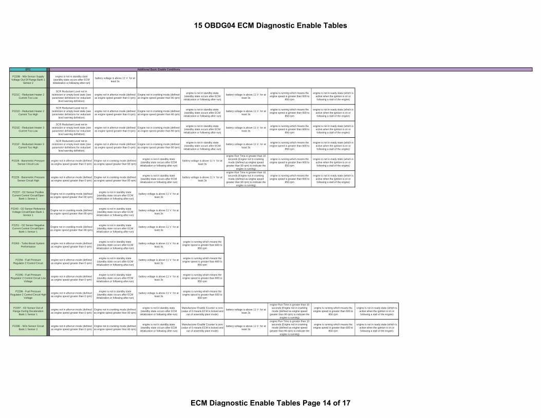
DTC Additional Basic Enable Conditions
P220B - N0x Sensor SupplyVoltage Out Of Range Bank 1
Sensor 2
engine is not in standby state(standby state occurs after ECMinitialization or following after-run)
battery voltage is above 11 V for atleast 3s
P221C - Reductant Heater 2Current Too Low
SCR Reductant Level not inrestriction or empty level state (seeparameter definitions for reductant
level warning definition)
engine not in afterrun mode (definedas engine speed greater than 0 rpm)
Engine not in cranking mode (definedas engine speed greater than 90 rpm)
engine is not in standby state(standby state occurs after ECMinitialization or following after-run)
battery voltage is above 11 V for atleast 3s
engine is running which means theengine speed is greater than 600 to
850 rpm
engine is not in ready state (which isactive when the ignition is on orfollowing a stall of the engine)
P221D - Reductant Heater 2Current Too High
SCR Reductant Level not inrestriction or empty level state (seeparameter definitions for reductant
level warning definition)
engine not in afterrun mode (definedas engine speed greater than 0 rpm)
Engine not in cranking mode (definedas engine speed greater than 90 rpm)
engine is not in standby state(standby state occurs after ECMinitialization or following after-run)
battery voltage is above 11 V for atleast 3s
engine is running which means theengine speed is greater than 600 to
850 rpm
engine is not in ready state (which isactive when the ignition is on orfollowing a stall of the engine)
P221E - Reductant Heater 3Current Too Low
SCR Reductant Level not inrestriction or empty level state (seeparameter definitions for reductant
level warning definition)
engine not in afterrun mode (definedas engine speed greater than 0 rpm)
Engine not in cranking mode (definedas engine speed greater than 90 rpm)
engine is not in standby state(standby state occurs after ECMinitialization or following after-run)
battery voltage is above 11 V for atleast 3s
engine is running which means theengine speed is greater than 600 to
850 rpm
engine is not in ready state (which isactive when the ignition is on orfollowing a stall of the engine)
P221F - Reductant Heater 3Current Too High
SCR Reductant Level not inrestriction or empty level state (seeparameter definitions for reductant
level warning definition)
engine not in afterrun mode (definedas engine speed greater than 0 rpm)
Engine not in cranking mode (definedas engine speed greater than 90 rpm)
engine is not in standby state(standby state occurs after ECMinitialization or following after-run)
battery voltage is above 11 V for atleast 3s
engine is running which means theengine speed is greater than 600 to
850 rpm
engine is not in ready state (which isactive when the ignition is on orfollowing a stall of the engine)
P2228 - Barometric PressureSensor Circuit Low
engine not in afterrun mode (definedas engine speed greater than 0 rpm)
Engine not in cranking mode (definedas engine speed greater than 90 rpm)
engine is not in standby state(standby state occurs after ECMinitialization or following after-run)
battery voltage is above 11 V for atleast 3s
engine Run Time is greater than 10seconds (Engine not in crankingmode (defined as engine speed
greater than 90 rpm) to indicate theengine is running)
engine is running which means theengine speed is greater than 600 to
850 rpm
engine is not in ready state (which isactive when the ignition is on orfollowing a stall of the engine)
P2229 - Barometric PressureSensor Circuit High
engine not in afterrun mode (definedas engine speed greater than 0 rpm)
Engine not in cranking mode (definedas engine speed greater than 90 rpm)
engine is not in standby state(standby state occurs after ECMinitialization or following after-run)
battery voltage is above 11 V for atleast 3s
engine Run Time is greater than 10seconds (Engine not in crankingmode (defined as engine speed
greater than 90 rpm) to indicate theengine is running)
engine is running which means theengine speed is greater than 600 to
850 rpm
engine is not in ready state (which isactive when the ignition is on orfollowing a stall of the engine)
P2237 - O2 Sensor PositiveCurrent Control Circuit/Open
Bank 1 Sensor 1
Engine not in cranking mode (definedas engine speed greater than 90 rpm)
engine is not in standby state(standby state occurs after ECMinitialization or following after-run)
battery voltage is above 11 V for atleast 3s
P2243 - O2 Sensor ReferenceVoltage Circuit/Open Bank 1
Sensor 1
Engine not in cranking mode (definedas engine speed greater than 90 rpm)
engine is not in standby state(standby state occurs after ECMinitialization or following after-run)
battery voltage is above 11 V for atleast 3s
P2251 - O2 Sensor NegativeCurrent Control Circuit/Open
Bank 1 Sensor 1
Engine not in cranking mode (definedas engine speed greater than 90 rpm)
engine is not in standby state(standby state occurs after ECMinitialization or following after-run)
battery voltage is above 11 V for atleast 3s
P2263 - Turbo Boost SystemPerformance
engine not in afterrun mode (definedas engine speed greater than 0 rpm)
engine is not in standby state(standby state occurs after ECMinitialization or following after-run)
battery voltage is above 11 V for atleast 3s
engine is running which means theengine speed is greater than 600 to
850 rpm
P2294 - Fuel PressureRegulator 2 Control Circuit
engine not in afterrun mode (definedas engine speed greater than 0 rpm)
engine is not in standby state(standby state occurs after ECMinitialization or following after-run)
battery voltage is above 11 V for atleast 3s
engine is running which means theengine speed is greater than 600 to
850 rpm
P2295 - Fuel PressureRegulator 2 Control Circuit Low
Voltage
engine not in afterrun mode (definedas engine speed greater than 0 rpm)
engine is not in standby state(standby state occurs after ECMinitialization or following after-run)
battery voltage is above 11 V for atleast 3s
engine is running which means theengine speed is greater than 600 to
850 rpm
P2296 - Fuel PressureRegulator 2 Control Circuit High
Voltage
engine not in afterrun mode (definedas engine speed greater than 0 rpm)
engine is not in standby state(standby state occurs after ECMinitialization or following after-run)
battery voltage is above 11 V for atleast 3s
engine is running which means theengine speed is greater than 600 to
850 rpm
P2297 - O2 Sensor Out ofRange During Deceleration
Bank 1 Sensor 1
engine not in afterrun mode (definedas engine speed greater than 0 rpm)
Engine not in cranking mode (definedas engine speed greater than 90 rpm)
engine is not in standby state(standby state occurs after ECMinitialization or following after-run)
Manufacturer Enable Counter is zero(value of 0 means ECM is locked and
out of assembly plant mode)
battery voltage is above 11 V for atleast 3s
engine Run Time is greater than 10seconds (Engine not in crankingmode (defined as engine speed
greater than 90 rpm) to indicate theengine is running)
engine is running which means theengine speed is greater than 600 to
850 rpm
engine is not in ready state (which isactive when the ignition is on orfollowing a stall of the engine)
P229E - NOx Sensor CircuitBank 1 Sensor 2
engine not in afterrun mode (definedas engine speed greater than 0 rpm)
Engine not in cranking mode (definedas engine speed greater than 90 rpm)
engine is not in standby state(standby state occurs after ECMinitialization or following after-run)
Manufacturer Enable Counter is zero(value of 0 means ECM is locked and
out of assembly plant mode)
battery voltage is above 11 V for atleast 3s
engine Run Time is greater than 10seconds (Engine not in crankingmode (defined as engine speed
greater than 90 rpm) to indicate theengine is running)
engine is running which means theengine speed is greater than 600 to
850 rpm
engine is not in ready state (which isactive when the ignition is on orfollowing a stall of the engine)
15 OBDG04 ECM Diagnostic Enable Tables
ECM Diagnostic Enable Tables Page 14 of 17

DTC Additional Basic Enable Conditions
P229F - NOx SensorPerformance Bank 1 Sensor 2
engine not in afterrun mode (definedas engine speed greater than 0 rpm)
Engine not in cranking mode (definedas engine speed greater than 90 rpm)
engine is not in standby state(standby state occurs after ECMinitialization or following after-run)
Manufacturer Enable Counter is zero(value of 0 means ECM is locked and
out of assembly plant mode)
ambient air temperature is above -7deg C ambient pressure is above 74.8kPa battery voltage is above 11 V for at
least 3s
engine Run Time is greater than 10seconds (Engine not in crankingmode (defined as engine speed
greater than 90 rpm) to indicate theengine is running)
engine is running which means theengine speed is greater than 600 to
850 rpm
engine is not in ready state (which isactive when the ignition is on or following
a stall of the engine)
P22A0 - NOx Sensor CircuitLow Bank 1 Sensor 2
engine not in afterrun mode (definedas engine speed greater than 0 rpm)
Engine not in cranking mode (definedas engine speed greater than 90 rpm)
engine is not in standby state(standby state occurs after ECMinitialization or following after-run)
Manufacturer Enable Counter is zero(value of 0 means ECM is locked and
out of assembly plant mode)
engine Run Time is greater than 10seconds (Engine not in crankingmode (defined as engine speed
greater than 90 rpm) to indicate theengine is running)
engine is running which means theengine speed is greater than 600 to
850 rpm
engine is not in ready state (which isactive when the ignition is on orfollowing a stall of the engine)
P22A1 - NOx Sensor CircuitHigh Bank 1 Sensor 2
engine not in afterrun mode (definedas engine speed greater than 0 rpm)
Engine not in cranking mode (definedas engine speed greater than 90 rpm)
engine is not in standby state(standby state occurs after ECMinitialization or following after-run)
Manufacturer Enable Counter is zero(value of 0 means ECM is locked and
out of assembly plant mode)
battery voltage is above 11 V for atleast 3s
engine Run Time is greater than 10seconds (Engine not in crankingmode (defined as engine speed
greater than 90 rpm) to indicate theengine is running)
engine is running which means theengine speed is greater than 600 to
850 rpm
engine is not in ready state (which isactive when the ignition is on orfollowing a stall of the engine)
P22A3 - NOx Heater ControlCircuit Bank 1 Sensor 2
engine not in afterrun mode (definedas engine speed greater than 0 rpm)
Engine not in cranking mode (definedas engine speed greater than 90 rpm)
engine is not in standby state(standby state occurs after ECMinitialization or following after-run)
Manufacturer Enable Counter is zero(value of 0 means ECM is locked and
out of assembly plant mode)
battery voltage is above 11 V for atleast 3s
engine Run Time is greater than 10seconds (Engine not in crankingmode (defined as engine speed
greater than 90 rpm) to indicate theengine is running)
engine is running which means theengine speed is greater than 600 to
850 rpm
engine is not in ready state (which isactive when the ignition is on orfollowing a stall of the engine)
P22A7 - NOx HeaterPerformance Bank 1 Sensor 2
engine not in afterrun mode (definedas engine speed greater than 0 rpm)
Engine not in cranking mode (definedas engine speed greater than 90 rpm)
engine is not in standby state(standby state occurs after ECMinitialization or following after-run)
Manufacturer Enable Counter is zero(value of 0 means ECM is locked and
out of assembly plant mode)
battery voltage is above 11 V for atleast 3s
engine Run Time is greater than 10seconds (Engine not in crankingmode (defined as engine speed
greater than 90 rpm) to indicate theengine is running)
engine is running which means theengine speed is greater than 600 to
850 rpm
engine is not in ready state (which isactive when the ignition is on orfollowing a stall of the engine)
P22FA - NOx Sensor 1Performance - Slow Response
High to Low
engine not in afterrun mode (definedas engine speed greater than 0 rpm)
Engine not in cranking mode (definedas engine speed greater than 90 rpm)
engine is not in standby state(standby state occurs after ECMinitialization or following after-run)
Manufacturer Enable Counter is zero(value of 0 means ECM is locked and
out of assembly plant mode)
battery voltage is above 11 V for atleast 3s
engine Run Time is greater than 10seconds (Engine not in crankingmode (defined as engine speed
greater than 90 rpm) to indicate theengine is running)
System is not in active regenerationmode
engine is running which means theengine speed is greater than 600 to
850 rpm
engine is not in ready state (which isactive when the ignition is on orfollowing a stall of the engine)
P22FE - NOx SensorPerformance - Sensing Element
Bank 1 Sensor 2
Manufacturer Enable Counter is zero(value of 0 means ECM is locked and
out of assembly plant mode)
ambient air temperature is above -7deg C ambient pressure is above 74.8kPa battery voltage is above 11 V for at
least 3s
engine Run Time is greater than 10seconds (Engine not in crankingmode (defined as engine speed
greater than 90 rpm) to indicate theengine is running)
System is not in active regenerationmode
P2428 - Exhaust Gas HighTemperature
engine not in afterrun mode (definedas engine speed greater than 0 rpm)
Engine not in cranking mode (definedas engine speed greater than 90 rpm)
engine is not in standby state(standby state occurs after ECMinitialization or following after-run)
engine is running which means theengine speed is greater than 600 to
850 rpm
engine is not in ready state (which isactive when the ignition is on orfollowing a stall of the engine)
P242B - Exhaust TemperatureSensor 3 Performance
engine not in afterrun mode (definedas engine speed greater than 0 rpm)
Engine not in cranking mode (definedas engine speed greater than 90 rpm)
engine is not in standby state(standby state occurs after ECMinitialization or following after-run)
battery voltage is above 11 V for atleast 3s
engine is running which means theengine speed is greater than 600 to
850 rpm
P242C - Exhaust GasTemperature (EGT) Sensor 3
Circuit Low Voltage
engine not in afterrun mode (definedas engine speed greater than 0 rpm)
Engine not in cranking mode (definedas engine speed greater than 90 rpm)
engine is not in standby state(standby state occurs after ECMinitialization or following after-run)
battery voltage is above 11 V for atleast 3s
engine is running which means theengine speed is greater than 600 to
850 rpm
P242D - Exhaust GasTemperature (EGT) Sensor 3
Circuit High Voltage
engine not in afterrun mode (definedas engine speed greater than 0 rpm)
Engine not in cranking mode (definedas engine speed greater than 90 rpm)
engine is not in standby state(standby state occurs after ECMinitialization or following after-run)
battery voltage is above 11 V for atleast 3s
engine is running which means theengine speed is greater than 600 to
850 rpm
P2453 - Diesel Particulate FilterDifferential Pressure Sensor
Performance
engine not in afterrun mode (definedas engine speed greater than 0 rpm)
Engine not in cranking mode (definedas engine speed greater than 90 rpm)
engine is not in standby state(standby state occurs after ECMinitialization or following after-run)
battery voltage is above 11 V for atleast 3s
engine Run Time is greater than 10seconds (Engine not in crankingmode (defined as engine speed
greater than 90 rpm) to indicate theengine is running)
engine is running which means theengine speed is greater than 600 to
850 rpm
engine is not in ready state (which isactive when the ignition is on orfollowing a stall of the engine)
P2454 - Diesel Particulate FilterDifferential Pressure Sensor
Circuit Low Voltage
engine not in afterrun mode (definedas engine speed greater than 0 rpm)
Engine not in cranking mode (definedas engine speed greater than 90 rpm)
engine is not in standby state(standby state occurs after ECMinitialization or following after-run)
battery voltage is above 11 V for atleast 3s
engine Run Time is greater than 10seconds (Engine not in crankingmode (defined as engine speed
greater than 90 rpm) to indicate theengine is running)
engine is running which means theengine speed is greater than 600 to
850 rpm
engine is not in ready state (which isactive when the ignition is on orfollowing a stall of the engine)
P2455 - Diesel Particulate FilterDifferential Pressure Sensor
Circuit High Voltage
engine not in afterrun mode (definedas engine speed greater than 0 rpm)
Engine not in cranking mode (definedas engine speed greater than 90 rpm)
engine is not in standby state(standby state occurs after ECMinitialization or following after-run)
battery voltage is above 11 V for atleast 3s
engine Run Time is greater than 10seconds (Engine not in crankingmode (defined as engine speed
greater than 90 rpm) to indicate theengine is running)
engine is running which means theengine speed is greater than 600 to
850 rpm
engine is not in ready state (which isactive when the ignition is on orfollowing a stall of the engine)
P2457 - Exhaust Gas (EGR)Cooler Performance
engine is not in standby state(standby state occurs after ECMinitialization or following after-run)
ambient pressure is above 74.8kPa battery voltage is above 11 V for atleast 3s
engine Run Time is greater than 10seconds (Engine not in crankingmode (defined as engine speed
greater than 90 rpm) to indicate theengine is running)
engine is running which means theengine speed is greater than 600 to
850 rpm
engine is not in ready state (which isactive when the ignition is on orfollowing a stall of the engine)
P2459 - Diesel Particulate FilterRegeneration Frequency ambient pressure is above 74.8kPa
15 OBDG04 ECM Diagnostic Enable Tables
ECM Diagnostic Enable Tables Page 15 of 17
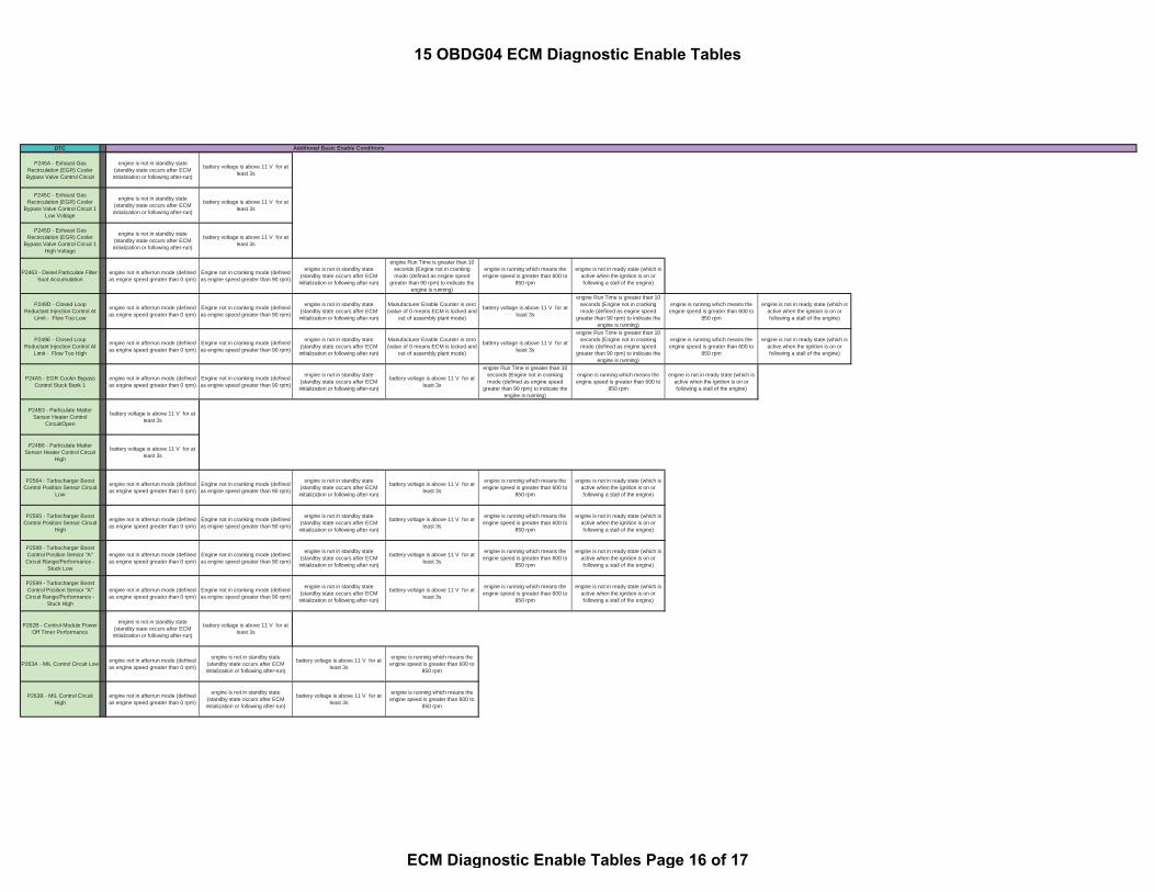
DTC Additional Basic Enable Conditions
P245A - Exhaust GasRecirculation (EGR) CoolerBypass Valve Control Circuit
engine is not in standby state(standby state occurs after ECMinitialization or following after-run)
battery voltage is above 11 V for atleast 3s
P245C - Exhaust GasRecirculation (EGR) Cooler
Bypass Valve Control Circuit 1Low Voltage
engine is not in standby state(standby state occurs after ECMinitialization or following after-run)
battery voltage is above 11 V for atleast 3s
P245D - Exhaust GasRecirculation (EGR) Cooler
Bypass Valve Control Circuit 1High Voltage
engine is not in standby state(standby state occurs after ECMinitialization or following after-run)
battery voltage is above 11 V for atleast 3s
P2463 - Diesel Particulate Filter -Soot Accumulation
engine not in afterrun mode (definedas engine speed greater than 0 rpm)
Engine not in cranking mode (definedas engine speed greater than 90 rpm)
engine is not in standby state(standby state occurs after ECMinitialization or following after-run)
engine Run Time is greater than 10seconds (Engine not in crankingmode (defined as engine speed
greater than 90 rpm) to indicate theengine is running)
engine is running which means theengine speed is greater than 600 to
850 rpm
engine is not in ready state (which isactive when the ignition is on orfollowing a stall of the engine)
P249D - Closed LoopReductant Injection Control At
Limit - Flow Too Low
engine not in afterrun mode (definedas engine speed greater than 0 rpm)
Engine not in cranking mode (definedas engine speed greater than 90 rpm)
engine is not in standby state(standby state occurs after ECMinitialization or following after-run)
Manufacturer Enable Counter is zero(value of 0 means ECM is locked and
out of assembly plant mode)
battery voltage is above 11 V for atleast 3s
engine Run Time is greater than 10seconds (Engine not in crankingmode (defined as engine speed
greater than 90 rpm) to indicate theengine is running)
engine is running which means theengine speed is greater than 600 to
850 rpm
engine is not in ready state (which isactive when the ignition is on orfollowing a stall of the engine)
P249E - Closed LoopReductant Injection Control At
Limit - Flow Too High
engine not in afterrun mode (definedas engine speed greater than 0 rpm)
Engine not in cranking mode (definedas engine speed greater than 90 rpm)
engine is not in standby state(standby state occurs after ECMinitialization or following after-run)
Manufacturer Enable Counter is zero(value of 0 means ECM is locked and
out of assembly plant mode)
battery voltage is above 11 V for atleast 3s
engine Run Time is greater than 10seconds (Engine not in crankingmode (defined as engine speed
greater than 90 rpm) to indicate theengine is running)
engine is running which means theengine speed is greater than 600 to
850 rpm
engine is not in ready state (which isactive when the ignition is on orfollowing a stall of the engine)
P24A5 - EGR Cooler BypassControl Stuck Bank 1
engine not in afterrun mode (definedas engine speed greater than 0 rpm)
Engine not in cranking mode (definedas engine speed greater than 90 rpm)
engine is not in standby state(standby state occurs after ECMinitialization or following after-run)
battery voltage is above 11 V for atleast 3s
engine Run Time is greater than 10seconds (Engine not in crankingmode (defined as engine speed
greater than 90 rpm) to indicate theengine is running)
engine is running which means theengine speed is greater than 600 to
850 rpm
engine is not in ready state (which isactive when the ignition is on orfollowing a stall of the engine)
P24B3 - Particulate MatterSensor Heater Control
Circuit/Open
battery voltage is above 11 V for atleast 3s
P24B6 - Particulate MatterSensor Heater Control Circuit
High
battery voltage is above 11 V for atleast 3s
P2564 - Turbocharger BoostControl Position Sensor Circuit
Low
engine not in afterrun mode (definedas engine speed greater than 0 rpm)
Engine not in cranking mode (definedas engine speed greater than 90 rpm)
engine is not in standby state(standby state occurs after ECMinitialization or following after-run)
battery voltage is above 11 V for atleast 3s
engine is running which means theengine speed is greater than 600 to
850 rpm
engine is not in ready state (which isactive when the ignition is on orfollowing a stall of the engine)
P2565 - Turbocharger BoostControl Position Sensor Circuit
High
engine not in afterrun mode (definedas engine speed greater than 0 rpm)
Engine not in cranking mode (definedas engine speed greater than 90 rpm)
engine is not in standby state(standby state occurs after ECMinitialization or following after-run)
battery voltage is above 11 V for atleast 3s
engine is running which means theengine speed is greater than 600 to
850 rpm
engine is not in ready state (which isactive when the ignition is on orfollowing a stall of the engine)
P2598 - Turbocharger BoostControl Position Sensor "A"
Circuit Range/Performance -Stuck Low
engine not in afterrun mode (definedas engine speed greater than 0 rpm)
Engine not in cranking mode (definedas engine speed greater than 90 rpm)
engine is not in standby state(standby state occurs after ECMinitialization or following after-run)
battery voltage is above 11 V for atleast 3s
engine is running which means theengine speed is greater than 600 to
850 rpm
engine is not in ready state (which isactive when the ignition is on orfollowing a stall of the engine)
P2599 - Turbocharger BoostControl Position Sensor "A"
Circuit Range/Performance -Stuck High
engine not in afterrun mode (definedas engine speed greater than 0 rpm)
Engine not in cranking mode (definedas engine speed greater than 90 rpm)
engine is not in standby state(standby state occurs after ECMinitialization or following after-run)
battery voltage is above 11 V for atleast 3s
engine is running which means theengine speed is greater than 600 to
850 rpm
engine is not in ready state (which isactive when the ignition is on orfollowing a stall of the engine)
P262B - Control Module PowerOff Timer Performance
engine is not in standby state(standby state occurs after ECMinitialization or following after-run)
battery voltage is above 11 V for atleast 3s
P263A - MIL Control Circuit Low engine not in afterrun mode (definedas engine speed greater than 0 rpm)
engine is not in standby state(standby state occurs after ECMinitialization or following after-run)
battery voltage is above 11 V for atleast 3s
engine is running which means theengine speed is greater than 600 to
850 rpm
P263B - MIL Control CircuitHigh
engine not in afterrun mode (definedas engine speed greater than 0 rpm)
engine is not in standby state(standby state occurs after ECMinitialization or following after-run)
battery voltage is above 11 V for atleast 3s
engine is running which means theengine speed is greater than 600 to
850 rpm
15 OBDG04 ECM Diagnostic Enable Tables
ECM Diagnostic Enable Tables Page 16 of 17

DTC Additional Basic Enable Conditions
P2687 - Fuel Supply HeaterControl Circuit/Open
battery voltage is above 11 V for atleast 3s
P2688 - Fuel Supply HeaterControl Circuit Low
battery voltage is above 11 V for atleast 3s
P2689 - Fuel Supply HeaterControl Circuit High
battery voltage is above 11 V for atleast 3s
P268C - Cylinder 1 InjectorData Incorrect
engine Run Time is greater than 10seconds (Engine not in crankingmode (defined as engine speed
greater than 90 rpm) to indicate theengine is running)
P268D - Cylinder 2 InjectorData Incorrect
engine Run Time is greater than 10seconds (Engine not in crankingmode (defined as engine speed
greater than 90 rpm) to indicate theengine is running)
P268E - Cylinder 3 InjectorData Incorrect
engine Run Time is greater than 10seconds (Engine not in crankingmode (defined as engine speed
greater than 90 rpm) to indicate theengine is running)
P268F - Cylinder 4 Injector DataIncorrect
engine Run Time is greater than 10seconds (Engine not in crankingmode (defined as engine speed
greater than 90 rpm) to indicate theengine is running)
P2A00 - O2 Sensor CircuitRange/Performance Bank 1
Sensor 1
Engine not in cranking mode (definedas engine speed greater than 90 rpm)
engine is not in standby state(standby state occurs after ECMinitialization or following after-run)
battery voltage is above 11 V for atleast 3s
P2BAA - NOx Exceedence -Low Reagent Consumption
SCR Reductant Level not inrestriction or empty level state (seeparameter definitions for reductant
level warning definition)
engine not in afterrun mode (definedas engine speed greater than 0 rpm)
Engine not in cranking mode (definedas engine speed greater than 90 rpm)
engine is not in standby state(standby state occurs after ECMinitialization or following after-run)
battery voltage is above 11 V for atleast 3s
engine Run Time is greater than 10seconds (Engine not in crankingmode (defined as engine speed
greater than 90 rpm) to indicate theengine is running)
engine is running which means theengine speed is greater than 600 to
850 rpm
engine is not in ready state (which isactive when the ignition is on orfollowing a stall of the engine)
U0073 - CAN A BUS OFF engine not in afterrun mode (definedas engine speed greater than 0 rpm)
engine is not in standby state(standby state occurs after ECMinitialization or following after-run)
battery voltage is above 11 V for atleast 3s
U0074 - CAN B BUS OFF engine not in afterrun mode (definedas engine speed greater than 0 rpm)
engine is not in standby state(standby state occurs after ECMinitialization or following after-run)
battery voltage is above 11 V for atleast 3s
U0101 - Lost CommunicationsWith Transmission Control
System
engine not in afterrun mode (definedas engine speed greater than 0 rpm)
engine is not in standby state(standby state occurs after ECMinitialization or following after-run)
battery voltage is above 11 V for atleast 3s
U0109 - Lost CommunicationWith Fuel Pump Control Module
"A"
engine not in afterrun mode (definedas engine speed greater than 0 rpm)
engine is not in standby state(standby state occurs after ECMinitialization or following after-run)
battery voltage is above 11 V for atleast 3s
15 OBDG04 ECM Diagnostic Enable Tables
ECM Diagnostic Enable Tables Page 17 of 17

GENERAL MOTORS CONFIDENTIAL
Component/System
FaultCode
Monitor StrategyDescription
MalfunctionCriteria
ThresholdValue
SecondaryParameters
EnableConditions
TimeRequired
MILIllumination
MechanicalActuatorPerformance(Functionality)
P059F Comparecommandedshutter positionto sensedposition
Failure to achieve commandedposition
Two (2) consecutiveintrusive tests fail toachieve commandedposition.
Intrusive tests aretriggered immediatelyfollowing any failure toachieve a commandedposition.
1. Power mode 1. Run/Crank Frequency:1 sample afterevery shuttermovement.
Intrusive testrequested if shuttermovement iscommanded andposition feedbackdiffers after 19.5seconds; otherwisereport pass.
Duration of intrusivetest is shuttermovement related(40 to 120 seconds)
DTC Type B2 trips
2. Shutter Control 2. Enabled3. Ignition Run/Crank Voltage 3. 11V < voltage < 32V
Control ModuleRead OnlyMemory (ROM)
P0601 This DTC will bestored if anysoftware orcalibration checksum is incorrect
Calculated Checksum (CRC16) ≠ stored checksum forany of the parts (boot,software, applicationcalibration, systemcalibration)
Ignition Run or Crank
1 failure if it occursduring the first ROMtest of the ignitioncycle, otherwise 5failures
DTC Type A1 trip
ORFrequency:Runs continuouslyin the background
HS Comm enabledControl ModuleNot Programmed
P0602 Indicates that theFSCM needs tobe programmed
This DTC is set via calibration,when
KeMEMD_b_NoStartCal = TRUEIgnition Run or Crank
Runs once at powerup
DTC Type A1 trip
ORIgn1 Accessory mode enabled
REVISED: 86.1844(d)(9)-PARMS-1
15 OBDG04 CCM/FSCM Summary Tables
CCM/FSCM Section Page 1 of 4

GENERAL MOTORS CONFIDENTIAL
Component/System
FaultCode
Monitor StrategyDescription
MalfunctionCriteria
ThresholdValue
SecondaryParameters
EnableConditions
TimeRequired
MILIllumination
Control ModuleLong TermMemory Reset
P0603 Non-volatilememorychecksum errorat controllerpower-up
Checksum at power-up ≠ checksum atpower-down
Ignition Run or Crank
1 failure
Frequency:Once at power-up
DTC Type A1 trip
ORIgn1 Accessory mode enabled
Control ModuleRandom AccessMemory (RAM)
P0604 Indicates thatcontrol module isunable tocorrectly writeand read data toand from RAM
Data read ≠ Data written
Ignition Run or Crank
1 failure if it occursduring the first RAMtest of the ignitioncycle, otherwise 5failures
DTC Type A1 trip
OR Frequency:Ign1 Accessory mode enabled Runs continuously
in the background.
Control ModuleInternalPerformance
1. MainProcessorConfigurationRegister Test
P0606
1. Register contents- All I/O configuration registerfaults - 1. <> correct value. 1. Ignition 1. Run or Crank
Tests 1 and 21 failureFrequency:Continuously(12.5ms)
DTC Type A1 trip
OR2. Ign1 Accessory mode 2. enabled
2. Processor clocktest
2. - Processor clock fault - a. EE latch flag set inEEPROM OR
2. a. == 0x5A5A
3. For all I/O configuration registerfaults:•KeMEMD_b_ProcFltCfgRegEnbl 3. TRUE
Test 33 failures out of 15samples
1 sample/12.5 msb. RAM latch flag. b. == 0x5A 4 . For Processor Clock Fault:
•KeMEMD_b_ProcFltCLKDiagEnbl
4. TRUE
This DTCindicates theECU hasdetected aninternalprocessor faultor externalwatchdog fault(PID 2032discriminates thesource of thefault )
REVISED: 86.1844(d)(9)-PARMS-2
15 OBDG04 CCM/FSCM Summary Tables
CCM/FSCM Section Page 2 of 4

GENERAL MOTORS CONFIDENTIAL
Component/System
FaultCode
Monitor StrategyDescription
MalfunctionCriteria
ThresholdValue
SecondaryParameters
EnableConditions
TimeRequired
MILIllumination
3. Externalwatchdog test
3. - External Watchdog Fault -Software control of fuel pumpdriver
3. = Control Lost 5. For External Watchdog Fault:•KeFRPD_b_FPExtWDogDiagEnbl
5. TRUE6. For External Watchdog Fault:•Control Module ROM(P0601)
6. not active7. For External Watchdog Fault:•Control Module RAM(P0604)
7. not activeControl ModuleLong TermMemory(EEPROM)Performance
P062F Indicates that theNVM Error flaghas not beencleared
Last EEPROM write Did not complete
Ignition Run or Crank
1 test failureOnce on controllerpower-up
DTC Type B2 trips
ORIgn1 Accessory mode enabled
Active Grille AirShutter Actuator 1Signal MessageCounter Incorrect
P151E Detects loss ofcommunicationcondition hasoccurredbetween ECUand Active GrillAir Shutter 1actuator
PWM Message Undetected 1. Power mode 1. Run/Crank Frequency: 100ms
150 failures out of167 samples
DTC Type B2 trips
2. Ignition Run/Crank Voltage 2. 11V < voltage < 32V
Ignition 1 SwitchCircuit LowVoltage
P2534 This DTC detectsif the Ignition1Switch circuit isshorted to low oropen
Ignition 1 voltage <= 6 V Engine Running180 failures out of200 samples
1 sample/25.0 ms
DTC Type A1 trip
REVISED: 86.1844(d)(9)-PARMS-3
15 OBDG04 CCM/FSCM Summary Tables
CCM/FSCM Section Page 3 of 4

GENERAL MOTORS CONFIDENTIAL
Component/System
FaultCode
Monitor StrategyDescription
MalfunctionCriteria
ThresholdValue
SecondaryParameters
EnableConditions
TimeRequired
MILIllumination
Ignition 1 SwitchCircuit HighVoltage
P2535 Detects if theIgnition1 Switchcircuit is shortedto vehicle supplyvoltage
Ignition 1 voltage > 11.7 V Ignition Run_Crank terminal Off180 failures out of200 samples
1 sample/25.0 ms
DTC Type A1 trip
Control ModuleCommunicationBus “A” Off
U0073 Detects that aCAN serial databus shortedcondition hasoccurred to forcethe CAN devicedriver to enter abus-off state
Bus Status Off Power mode Run/Crank 5 failures out of 5samples ( 5seconds)
DTC Type B2 trips
LostCommunicationWith ECM/PCM“A”
U0100 Detects that CANserial datacommunicationhas been lostwith the ECM
Message $0C9 Undetected 1. Power mode 1. Run/Crank 12 failures out of 12samples (12seconds)
DTC Type B2 trips
2. Ignition Run/Crank Voltage 2. 11V<voltage<32V3. U0073 3. not active
REVISED: 86.1844(d)(9)-PARMS-4
15 OBDG04 CCM/FSCM Summary Tables
CCM/FSCM Section Page 4 of 4

Component / Fault Monitor Strategy Primary Malfunction Secondary Time MILSystem Code Description Criteria Parameters Required Illum.
Glow Plug ControlModulePerformance
P064C Electronic circuitrydetermines fault with GPswitch
Glow Plug Currentand
Glow plug is commandedand
voltage at glow plug
<
=
=
6.6
On
0
amps
volts
glow plugs are commanded on
DTCs P163C, P0671-P0678
= True
Not set
failconditionsexists for 3.5seconds.monitor runswith 0.5 sratewheneverenableconditionsare met.
B
Checksum error betweencalculated and stored valuesare compared
ROM error: Checksums match = NO Module power On failconditionsexists for 4.5s.monitor runswith 1.5 sratewheneverenableconditionsare met.
Compariarson of read writevalues
RAM error: Read write values match = NO Module power On failconditionsexists for 3.2seconds.monitor runswith 0.2 sratewheneverenableconditionsare met.
Checksum error betweencalculated and stored values
EEPROM error: Checksums match = NO Module power On failconditionsexists for 3.2seconds.monitor runswith 0.2 sratewheneverenableconditionsare met.
Logic and Value ConditionsThreshold Enable
15 OBDG04 GPCM Summary Tables
GPCM Section Page 1 of 10

Component / Fault Monitor Strategy Primary Malfunction Secondary Time MILSystem Code Description Criteria Parameters Required Illum.Logic and Value Conditions
Threshold Enable
measured voltage of chargepump is determined to beout of tolerance
Charge Pump Under voltage <= Battery voltageat GPCM + 7
volts Battery voltage at GPCM > 6 volts failconditionsexists for3.13seconds.monitor runswith 0.13 sratewheneverenableconditionsare met
measured voltage of chargepump is determined to beout of tolerance
Charge Pump Over voltage >= Battery voltageat GPCM + 18
volts Battery < 19.9 volts failconditionsexists for3.16seconds.monitor runswith 0.16 sratewheneverenableconditionsare met
Elecrtonic circuitrydetermines that the reversepolarity protection voltagedrop is in range
GPCM reverse polarity switch "highvoltage drop"
Path 1 [Battery voltage at GPCM - meanglow plug voltage value]
Path 2 (Battery voltage at GPCM - meanglow plug voltage value with charge pump
off) - (Battery - mean glow plug voltagevalue with charge pu
>
<
2.3
0.300
volts
volts
glow plugs are commandedBattery voltage at GPCM
GP currentGP current
P0671,P0672, P0675, P0676Battery voltage at GPCM stable for
30ms
=>><=<
On 6 660
Not set2
voltsampsamps
volts
Path1: failconditionsexists for 9seconds.monitor runswith 6 s ratewheneverenableconditionsare met.Path2: failconditionsexists for 13seconds.monitor runswith 10 sratewheneverenableconditionsare met.
Internal and externalWatchdogs are monitoredfor interuptionMonitor for undefinedinstruction code interuptMonitor for osolation stopdetection
GPCM running reset: number of runningresets
orundefined instruction code detected
orOsolation stop detection
> 9 events in a row none failconditionsexists for 5seconds.monitor runswith 2 s ratewheneverenableconditionsare met.
15 OBDG04 GPCM Summary Tables
GPCM Section Page 2 of 10

Component / Fault Monitor Strategy Primary Malfunction Secondary Time MILSystem Code Description Criteria Parameters Required Illum.Logic and Value Conditions
Threshold Enable
GMLAN Battery voltage fromECM is compared to GPCMinternal measured batteryvoltage
difference between internal and externalvalue of battery voltage too high
abs[GPCM internal measured batteryvoltage - GMLAN Battery voltage]
'> 3 voltsglow plugs are commanded
GMLAN battery signalglow command messageBattery voltage at GPCM
RPMRPM
===>
<=>=
Onvalidvalid
610
400
volts
failconditionsexists for3.19seconds.monitor runswith 0.19 sratewheneverenableconditionsare met
measure temperature of theSBC
system basic chip (SBC) overtemperature: temperature of the high
side switch inside the SBC
> 155 deg C Internal GPCM temperature < 100 deg C failconditionsexists for3.13seconds.monitor runswith 0.13 sratewheneverenableconditionsare met
Electronic circuitry detects afailure in the NOx sensorpower supply
NOx sensor power supply fault:Path1: DC/DC booster current.
ForPath 2: DC/DC booster current.
Path 3: voltage at main switch
Path 4: (DC/DC Booster voltage - GPCMbattery voltage)
> >>
=
=
25640
60 (by hardwareprotection (time
varies withtemperature))
0
± 3
ampsmsecamps
volts
volts
Battery voltage at the GPCM
Battery voltage at the GPCM
>
=
6
8 to 14
volts
volts
failconditionsexists for 9seconds.monitor runswith 6 s ratewheneverenableconditionsare met.
Checksum error betweencalculated and stored values
DEF heater current not calibrated.:Checksums match
= No Ignition on failconditionsexists for 3.2seconds.monitor runswith 0.2 sratewheneverenableconditionsare met.
15 OBDG04 GPCM Summary Tables
GPCM Section Page 3 of 10
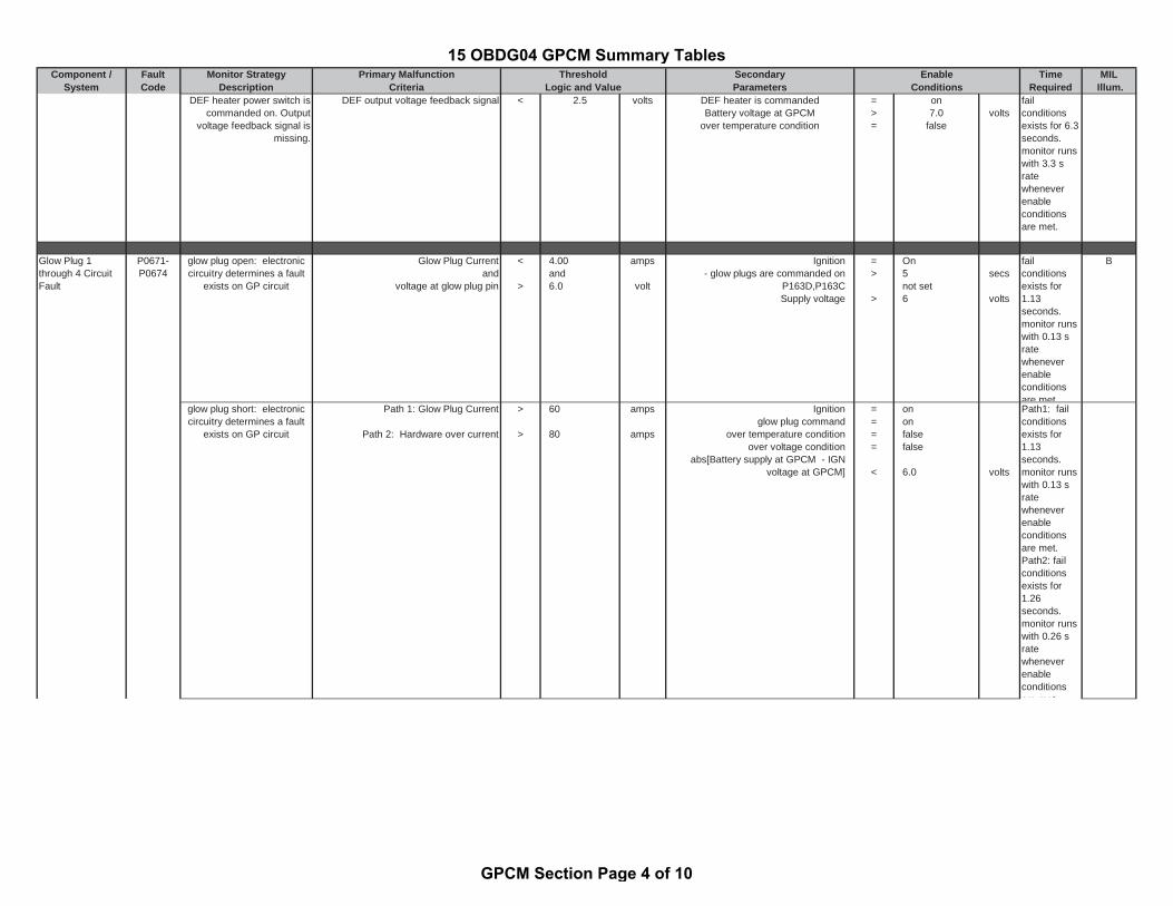
Component / Fault Monitor Strategy Primary Malfunction Secondary Time MILSystem Code Description Criteria Parameters Required Illum.Logic and Value Conditions
Threshold Enable
DEF heater power switch iscommanded on. Output
voltage feedback signal ismissing.
DEF output voltage feedback signal < 2.5 volts DEF heater is commandedBattery voltage at GPCM
over temperature condition
=>=
on7.0
falsevolts
failconditionsexists for 6.3seconds.monitor runswith 3.3 sratewheneverenableconditionsare met.
Glow Plug 1through 4 CircuitFault
P0671-P0674
glow plug open: electroniccircuitry determines a fault
exists on GP circuit
Glow Plug Currentand
voltage at glow plug pin
<
>
4.00and6.0
amps
volt
Ignition- glow plugs are commanded on
P163D,P163CSupply voltage
=>
>
On5not set6
secs
volts
failconditionsexists for1.13seconds.monitor runswith 0.13 sratewheneverenableconditionsare met
B
glow plug short: electroniccircuitry determines a fault
exists on GP circuit
Path 1: Glow Plug Current
Path 2: Hardware over current
>
>
60
80
amps
amps
Ignitionglow plug command
over temperature conditionover voltage condition
abs[Battery supply at GPCM - IGNvoltage at GPCM]
====
<
ononfalsefalse
6.0 volts
Path1: failconditionsexists for1.13seconds.monitor runswith 0.13 sratewheneverenableconditionsare met.Path2: failconditionsexists for1.26seconds.monitor runswith 0.26 sratewheneverenableconditionsare met
15 OBDG04 GPCM Summary Tables
GPCM Section Page 4 of 10
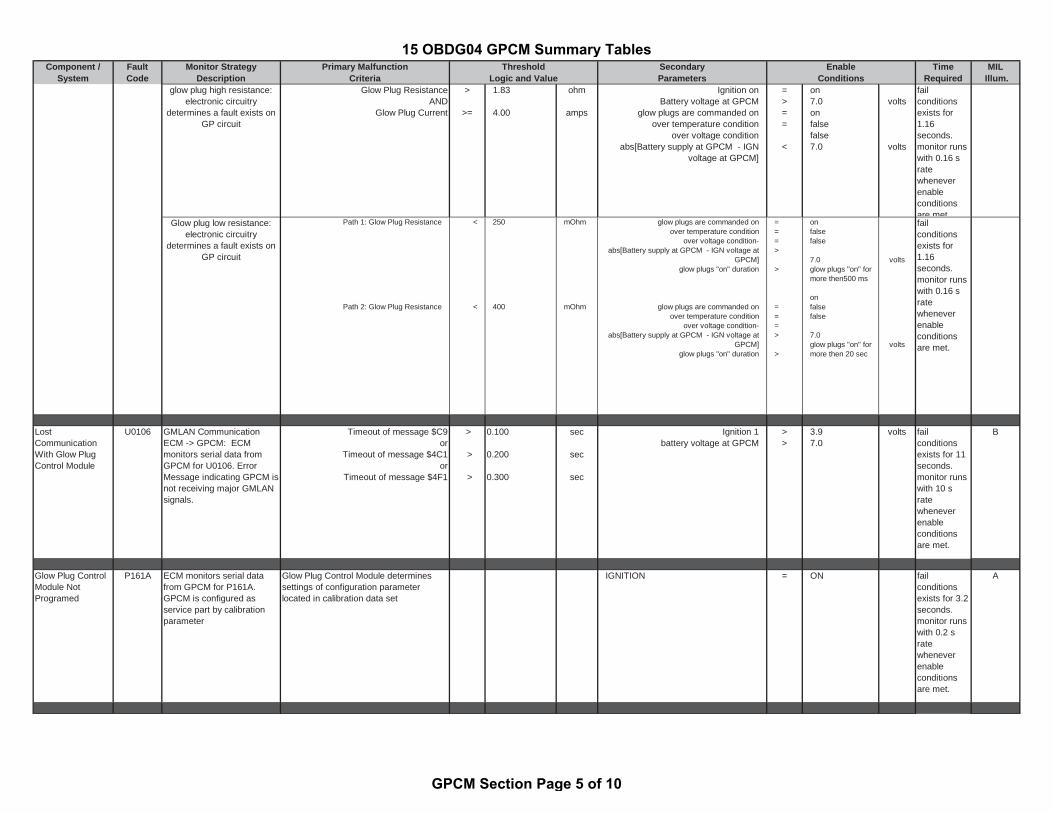
Component / Fault Monitor Strategy Primary Malfunction Secondary Time MILSystem Code Description Criteria Parameters Required Illum.Logic and Value Conditions
Threshold Enable
glow plug high resistance:electronic circuitry
determines a fault exists onGP circuit
Glow Plug ResistanceAND
Glow Plug Current
>
>=
1.83
4.00
ohm
amps
Ignition on Battery voltage at GPCM
glow plugs are commanded onover temperature condition
over voltage conditionabs[Battery supply at GPCM - IGN
voltage at GPCM]
=>==
<
on7.0onfalsefalse7.0
volts
volts
failconditionsexists for1.16seconds.monitor runswith 0.16 sratewheneverenableconditionsare met
Glow plug low resistance:electronic circuitry
determines a fault exists onGP circuit
Path 1: Glow Plug Resistance
Path 2: Glow Plug Resistance
<
<
250
400
mOhm
mOhm
glow plugs are commanded onover temperature condition
over voltage condition-abs[Battery supply at GPCM - IGN voltage at
GPCM]glow plugs "on" duration
glow plugs are commanded onover temperature condition
over voltage condition-abs[Battery supply at GPCM - IGN voltage at
GPCM]glow plugs "on" duration
===>
>
===>
>
onfalsefalse
7.0glow plugs "on" formore then500 ms
onfalsefalse
7.0glow plugs "on" formore then 20 sec
volts
volts
failconditionsexists for1.16seconds.monitor runswith 0.16 sratewheneverenableconditionsare met.
LostCommunicationWith Glow PlugControl Module
U0106 GMLAN CommunicationECM -> GPCM: ECMmonitors serial data fromGPCM for U0106. ErrorMessage indicating GPCM isnot receiving major GMLANsignals.
Timeout of message $C9or
Timeout of message $4C1or
Timeout of message $4F1
>
>
>
0.100
0.200
0.300
sec
sec
sec
Ignition 1battery voltage at GPCM
>>
3.97.0
volts failconditionsexists for 11seconds.monitor runswith 10 sratewheneverenableconditionsare met.
B
Glow Plug ControlModule NotProgramed
P161A ECM monitors serial datafrom GPCM for P161A.GPCM is configured asservice part by calibrationparameter
Glow Plug Control Module determinessettings of configuration parameterlocated in calibration data set
IGNITION = ON failconditionsexists for 3.2seconds.monitor runswith 0.2 sratewheneverenableconditionsare met.
A
15 OBDG04 GPCM Summary Tables
GPCM Section Page 5 of 10

Component / Fault Monitor Strategy Primary Malfunction Secondary Time MILSystem Code Description Criteria Parameters Required Illum.Logic and Value Conditions
Threshold Enable
Glow Plug ModulePrimary Circuit
P163C Electronic GPCM circuitrydetermines the voltagesupply to GPCM is out ofrange
PATH 1: voltage supply to GPCM
or
PATH 2: (IGN - voltage supply toGPCM)
or
PATH 3: (ECM reported voltage via CAN -voltage supply to GPCM)
<
>
>
6.0
+/-5
+/-3
volt
volt
volt
GPCM Ignition voltage
or
GPCM voltage supplyGPCM Ignition voltage
or
GPCM supply voltageEngine speed
><
><
>>
9.016
6.04.0
610< rpm >400
voltvolt
voltvolt
voltrpm
failconditionsexists for 4seconds.monitor runswith 1 s ratewheneverenableconditionsare met.
B
Glow Plug ModuleSecondary Circuit
P163D Electronic GPCM circuitrydetermines serveral signalvoltage levels to GPCM areout of range
Path 1: Key state (Ign 1)
or
Path 2: Electronic circuitry determinesvoltage at glow plug pin
or
Path 3: [GPCM ground - GP ground]
=
>
>
OFF
6.0
1.5
volt
volts
Path 1 glow plug activation request fromECM
or
Path 2 GP commanded
or
Path 3 GP commandedDTCs not setIAH dutycycle
=
=
=
=
ON
or
Off
or
ONP0671,P06750 or 100 %
failconditionsexists for 4seconds.monitor runswith 1 s ratewheneverenableconditionsare met.
B
Reductant Heater1 Control Circuit
P20B9 ECM monitors serial datafrom GPCM for P20B9Error Message indicatingGPCM detects reductantheater not connected toGPCM or an interruption
reductant heater currentand
voltage at heater pin
<
>
0.2and3.0
amp
volt
DTCs not set:reductan heater commanded:
GPCM temperatureGPCM battery supply voltage
=<>
P20BBON1237.0
°Cvolt
failconditionsexists for3.94seconds.monitor runswith 3.44 sratewheneverenableconditionsare met
A
Reductant Heater1 Control CircuitLow voltage
P20BB ECM monitors serial datafrom GPCM for P20BBError Message indicatingGPCM detects reductantheater output shorted toground or an overloadcondition
Path 1: Reductant Heater Plug Current
or
Path 2: load at output (detected byhardware)
Path 3: hardware over currentPath 4: hardware over temperature
condition
>
<
>>
21
or
0.047
27175
amp
ohm
amp°C
reductan heater commanded:GPCM temperature
GPCM supply voltage KL30
or
reductan heater commanded:GPCM temperature
GPCM supply voltage KL30
=<>
or
=<>
ON1237.0
or
ON1237.0
°Cvoltvolt
or
°Cvolt
failconditionsexists for 1.5seconds.monitor runswith 1 s ratewheneverenableconditionsare met.
A
15 OBDG04 GPCM Summary Tables
GPCM Section Page 6 of 10
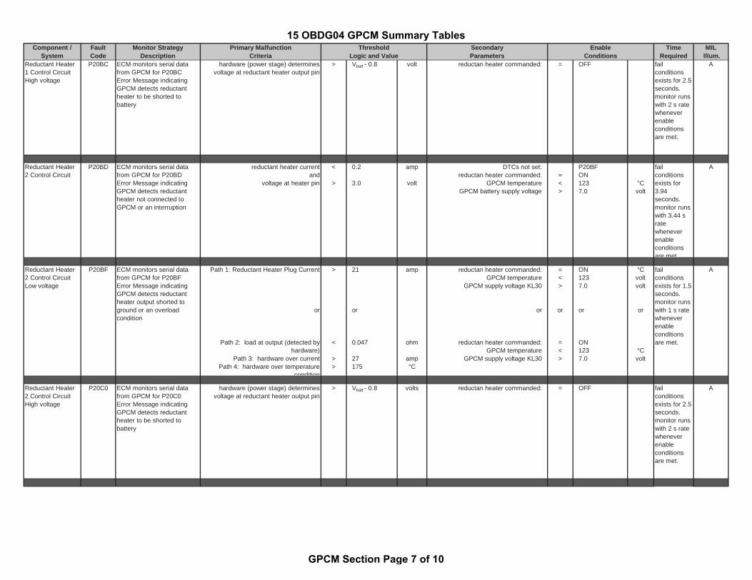
Component / Fault Monitor Strategy Primary Malfunction Secondary Time MILSystem Code Description Criteria Parameters Required Illum.Logic and Value Conditions
Threshold Enable
Reductant Heater1 Control CircuitHigh voltage
P20BC ECM monitors serial datafrom GPCM for P20BCError Message indicatingGPCM detects reductantheater to be shorted tobattery
hardware (power stage) determinesvoltage at reductant heater output pin
> Vbatt - 0.8 volt reductan heater commanded: = OFF failconditionsexists for 2.5seconds.monitor runswith 2 s ratewheneverenableconditionsare met.
A
Reductant Heater2 Control Circuit
P20BD ECM monitors serial datafrom GPCM for P20BDError Message indicatingGPCM detects reductantheater not connected toGPCM or an interruption
reductant heater currentand
voltage at heater pin
<
>
0.2
3.0
amp
volt
DTCs not set:reductan heater commanded:
GPCM temperatureGPCM battery supply voltage
=<>
P20BFON1237.0
°Cvolt
failconditionsexists for3.94seconds.monitor runswith 3.44 sratewheneverenableconditionsare met
A
Reductant Heater2 Control CircuitLow voltage
P20BF ECM monitors serial datafrom GPCM for P20BFError Message indicatingGPCM detects reductantheater output shorted toground or an overloadcondition
Path 1: Reductant Heater Plug Current
or
Path 2: load at output (detected byhardware)
Path 3: hardware over currentPath 4: hardware over temperature
condition
>
<
>>
21
or
0.047
27175
amp
ohm
amp°C
reductan heater commanded:GPCM temperature
GPCM supply voltage KL30
or
reductan heater commanded:GPCM temperature
GPCM supply voltage KL30
=<>
or
=<>
ON1237.0
or
ON1237.0
°Cvoltvolt
or
°Cvolt
failconditionsexists for 1.5seconds.monitor runswith 1 s ratewheneverenableconditionsare met.
A
Reductant Heater2 Control CircuitHigh voltage
P20C0 ECM monitors serial datafrom GPCM for P20C0Error Message indicatingGPCM detects reductantheater to be shorted tobattery
hardware (power stage) determinesvoltage at reductant heater output pin
> Vbatt - 0.8 volts reductan heater commanded: = OFF failconditionsexists for 2.5seconds.monitor runswith 2 s ratewheneverenableconditionsare met.
A
15 OBDG04 GPCM Summary Tables
GPCM Section Page 7 of 10

Component / Fault Monitor Strategy Primary Malfunction Secondary Time MILSystem Code Description Criteria Parameters Required Illum.Logic and Value Conditions
Threshold Enable
Reductant Heater3 Control Circuit
P20C1 ECM monitors serial datafrom GPCM for P20C1Error Message indicatingGPCM detects reductantheater not connected toGPCM or an interruption
reductant heater currentand
voltage at heater pin
<
>
0.2and3.0
amp
volt
DTCs not set:reductan heater commanded:
GPCM temperatureGPCM battery supply voltage
=<>
P20C3ON1237.0
°Cvolt
failconditionsexists for3.94seconds.monitor runswith 3.44 sratewheneverenableconditionsare met
A
Reductant Heater3 Control CircuitLow voltage
P20C3 ECM monitors serial datafrom GPCM for P20C3Error Message indicatingGPCM detects reductantheater output shorted toground or an overloadcondition
Path 1: Reductant Heater Plug Current
or
Path 2: load at output (detected byhardware)
Path 3: hardware over currentPath 4: hardware over temperature
condition
>
<
>>
21
or
0.047
27175
amp
ohm
amp°C
reductan heater commanded:GPCM temperature
GPCM supply voltage KL30
or
reductan heater commanded:GPCM temperature
GPCM supply voltage KL30
=<>
or
=<>
ON1237.0
or
ON1237.0
°Cvoltvolt
or
°Cvolt
failconditionsexists for 1.5seconds.monitor runswith 1 s ratewheneverenableconditionsare met.
A
Reductant Heater3 Control CircuitHigh voltage
P20C4 ECM monitors serial datafrom GPCM for P20C4Error Message indicatingGPCM detects reductantheater to be shorted tobattery
hardware (power stage) determinesvoltage at reductant heater output pin
> Vbatt - 0.8 volts reductan heater commanded: = OFF failconditionsexists for 2.5seconds.monitor runswith 2 s ratewheneverenableconditionsare met.
A
Nox Sensor Supplyvoltage CircuitBank 1 Sensor 1
P220A ECM monitors serial datafrom GPCM for P220AError Message indicatingGPCM detects DC/DCbooster output shorted toground or shorted to battery
PATH 1:GPCM Electronic circuitrydetermines voltage at DC/DC booster
output pin
or
PATH 2: DC/DC booster output currentduration
or
PATH 3: DC/DC booster output currentduration
>
>>
>>
5.0
5.00.010
37.50.000020
volt
ampsec
ampsec
status DC/DC booster
or
status DC/DC booster
or
status Dc/DC booster
=
=
=
OFF,power upprocedure hasstarted afterreset
ON
ON
failconditionsexists for 5.5seconds.monitor runswith 5 s ratewheneverenableconditionsare met.
B
15 OBDG04 GPCM Summary Tables
GPCM Section Page 8 of 10

Component / Fault Monitor Strategy Primary Malfunction Secondary Time MILSystem Code Description Criteria Parameters Required Illum.Logic and Value Conditions
Threshold Enable
Nox Sensor Supplyvoltage CircuitBank 1 Sensor 2
P220B ECM monitors serial datafrom GPCM for P220BError Message indicatingGPCM detects DC/DCbooster output shorted toground or shorted to battery
PATH 1:Electronic circuitry determinesvoltage at DC/DC booster output pin
or
PATH 2: DC/DC booster output currentduration
or
PATH 3: DC/DC booster output currentduration
>
>>
>>
5.0
5.00.010
37.50.000020
volt
ampsec
ampsec
status DC/DC booster
or
status DC/DC booster
or
status Dc/DC booster
=
=
=
OFF,power upprocedure hasstarted afterreset
or
ON
or
ON
failconditionsexists for 5.5seconds.monitor runswith 5 s ratewheneverenableconditionsare met.
B
Glow Plug ControlModuleTemperatureSensor Circuit Lowvoltage
P16AD ECM monitors serial datafrom GPCM for P16ADError Message indicatingGPCM detects GPCMtemperature sensore voltageout of range low
PATH 1: GPCM temperature sensorvoltage
PATH 2: GPCM temperature sensorvoltage
<
<
0.210
0.615
volts
volts
Engine Off Timer (GMLAN) andIntake Air Temperature (GMLAN)
or
Engine Coolant Temperature (GMLAN)and
Intake Air Temperature (GMLAN)
( Engine Off Timer (GMLAN) or Intake Air Temperature (GMLAN) )
and( Engine Coolant Temperature
(GMLAN) orIn
>=>=
>>
<<
<=<=
28800-7
70-10
28800-7
60-10
sec°C
°C°C
sec°C
°C°C
failconditionsexists for1.81seconds.monitor runswith 1.31 sratewheneverenableconditionsare met.
B
Glow Plug ControlModuleTemperatureSensor CircuitHigh voltage
P16AE ECM monitors serial datafrom GPCM for P16AEError Message indicatingGPCM detects GPCMtemperature sensore voltageour of range high
GPCM temperature sensor voltage > 4,94 volts Engine Off Timer (GMLAN) andIntake Air Temperature (GMLAN)
or
Engine Coolant Temperature (GMLAN)and
Intake Air Temperature (GMLAN)
>=>=
>>
28800-7
70-10
sec°C
°C°C
failconditionsexists for1.81seconds.monitor runswith 1.31 sratewheneverenableconditionsare met
B
15 OBDG04 GPCM Summary Tables
GPCM Section Page 9 of 10

Component / Fault Monitor Strategy Primary Malfunction Secondary Time MILSystem Code Description Criteria Parameters Required Illum.Logic and Value Conditions
Threshold Enable
Glow Plug ControlModule Temperature-Engine Intake AirTemperature NotPlausible
P16A8 ECM monitors serial data fromGPCM for P16A8Error Message indicating GPCMdetects GPCM temperature andengine intake air temperature(GMLAN) are not plausible
Tenperature difference between internaltemperature of GPCM and engine intake air
temperature (GMLAN)
> absolute 20 °C Engine Off Timer (GMLAN) andIntake Air Temperature (GMLAN) and
>=>
28800-7
sec°C
failconditionsexists for 2.5seconds.monitor runswith 2 s ratewheneverenableconditionsare met.
B
15 OBDG04 GPCM Summary Tables
GPCM Section Page 10 of 10