echnical guidance document number - … · a hydrocarbon liquids withdrawn from an atmospheric...
TRANSCRIPT

CCAC O&G Methane Partnership – Technical Guidance Document Number 6: Unstabilized Hydrocarbon Liquid Storage Tanks Modified: April 2017
Page 1 of 13
SG. 17.1.6
TECHNICAL GUIDANCE DOCUMENT NUMBER 6:
UNSTABILIZED HYDROCARBON LIQUID STORAGE TANKS
Introduction This document provides technical guidance to Partners of the CCAC Oil and Gas Methane Partnership (OGMP). It is one in a series describing a core source of methane emissions from oil and natural gas production operations. The guidance documents introduce suggested methodologies for quantifying methane emissions from specific sources and describes established mitigation options that Partners should reference when determining if the source is “mitigated.”1 The OGMP recognizes that the equipment and processes described in these documents are found in a variety of oil and gas operations, including onshore, offshore, and remote operations, and the way in which the emissions are quantified and mitigated may vary across locations and operational environments. As such, operational conditions, as well as logistical, safety and cost considerations, must be evaluated on a case-by-case basis. The OGMP assumes that methane emission mitigation actions that require shut-downs of non-redundant equipment/processes (e.g., that would result in a stoppage of operations) would be carried out during regularly scheduled maintenance activities, unless the Partner deems the corrective action to be worthy of an early/additional shut-down.
Description of Source Storage vessels in the oil and natural gas sector are used to hold a variety of liquids, including crude oil, condensates, and produced water. Crude oil and condensate may be stored in fixed-roof, atmospheric pressure tanks between production wells and pipeline or truck transportation. In offshore fields, the storage tanks on production platforms, floating production, storage and offloading (FPSO) vessels and floating storage and offloading (FSO) vessels contain crude oil and/or condensate, produced from connected wells or coming from nearby platforms. Light hydrocarbons dissolved in the crude oil or condensate under pressure (i.e. unstabilized hydrocarbon liquids)—including methane and other volatile organic compounds (VOC), natural gas liquids (NGLs), hazardous air pollutants (HAP), and some inert gases—will flash (vaporize) from the liquid stored in the tank and accumulate in the vapor space between the liquid surface, the walls and roof of the tank. Fixed roof tanks can not contain any significant pressure above atmospheric pressure, and therefore these vapors must be vented. Emissions from storage vessels are a combination of flash, working, and standing losses. Flash losses (the most significant of the three) occur when a pressurized liquid with dissolved gases is transferred from a well or vessel at higher pressure to a fixed roof, atmospheric pressure tank. The pressure drop causes gas to rapidly evolve from the liquid and/or vaporize (i.e., flash). Working losses refer to vapors above the liquid surface pushed out by rising liquid levels and agitation of liquids in tanks associated with circulation of fresh liquid through them. Standing losses refer to vapors expanding and venting associated with daily and seasonal temperature and barometric pressure changes. Onshore field production sites are generally
1 For reporting purposes as described in the CCAC Oil and Gas Methane Partnership Framework, Section 3.

CCAC O&G Methane Partnership – Technical Guidance Document Number 6: Unstabilized Hydrocarbon Liquid Storage Tanks Modified: April 2017
Page 2 of 13
designed and operated to push the liquid from a gas/liquid separator vessel at a higher pressure to the tank so that the liquid will fill the tank without the use of a pump. This results in some flashing emissions. The volume of vapor emitted from a fixed-roof storage tank is dependent on several factors, most significantly the pressure in the gas/liquid separator and the oil or condensate flow rate from this separator into the tank. That is, the greater the differential in pressure between the separator and tank, the higher the flashing losses. Lighter crude oils (API gravity >36°) flash more hydrocarbon vapors than heavier crudes (API gravity <36°) at the same separator pressure. Additionally, in storage tanks where oil cycling is frequent and overall throughput is high, more working losses will occur than in tanks with low throughput and where oil is held for longer periods of time. The composition of tank vapors varies based on the type of production and the types of hydrocarbons that are being produced from the reservoir. Often methane is the primary component of tank vapors (between 40 and 80 percent for crude oil and gas condensate), but other compounds may be present in lesser quantities, including more complex hydrocarbon compounds such as ethane, propane, butanes, pentanes, natural inert gases such as nitrogen and carbon dioxide, and hazardous air pollutants, like hydrogen sulfide, benzene, toluene, ethyl-benzene, and xylene.
Hydrocarbon liquid storage tanks may be configured in a variety of ways, and the configuration should be identified to determine whether the source is mitigated or unmitigated. Some options include the following:
Table 6.1: Configurations for Unstabilized Hydrocarbon Liquid Storage TanksA
Configuration Mitigated or Unmitigated
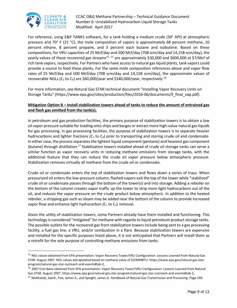
Tank vapors are emitted to the atmosphere via routing through an open vent, unlit flare2, and/or through openings in the fixed roof of an
oil or condensate production tank (e.g., open/unsealed thief hatch, cracks/corrosion in tank roof, weighted pressure/vacuum relief valve).
Exhibit A
Unmitigated
Tank vapors are recovered by routing to a Vapor Recovery Unit (VRU) system and directing to productive use (e.g., fuel gas, compressor
suction, gas lift). Exhibit B
Mitigated (if confirmed to be functioning with lowB or no
emissions) (OPTION A)
Stabilization towers are installed ahead of tanks to reduce the amount of entrained gas and flash gas emitted from the tank(s).
Mitigated (if confirmed to be functioning with lowB or no
emissions) (OPTION B)
Tank vapors are routed to a flare/combustion device.
Mitigated (if confirmed to be functioning with lowB or no
emissions) (OPTION C)
A Hydrocarbon liquids withdrawn from an atmospheric pressure storage tank or vessel, or from a vapor stripping
tower, are considered stabilized (i.e. volatile gases are expelled). Stabilized oil can be stored in a floating roof
2 “Flare” in this document refers to vertical combustion devices using an open or enclosed flame.

CCAC O&G Methane Partnership – Technical Guidance Document Number 6: Unstabilized Hydrocarbon Liquid Storage Tanks Modified: April 2017
Page 3 of 13
tank, which is not considered to be a significant source of methane emissions and is therefore not considered to be a core source. Note that unstabilized oil cannot be stored in a floating roof tank. BExpected emissions levels if mitigation option is in place and functioning properly (e.g., flare is not extinguished,
etc.).
Partners should quantify and evaluate for mitigation any of the configurations above that are not identified as “mitigated” for methane emissions, per the sections below. As part of their periodic evaluation plans, Partners should include inspection of mitigated tanks in their Annual Operations/Assets Surveys to ensure proper functionality. Malfunctions (e.g., VRU or stabilization towers are not functioning or an extinguished flare) may result in higher than designed methane emissions. Though unusual, situations have also been observed in which gas from the separator is permanently routed to the atmosphere (e.g., when there is no market for the gas), in which case this should count as an additional source of “unmitigated” emissions that needs to be quantified and addressed. At times, unintended methane emissions not associated with crude oil or condensate flashing may enter and vent from tanks. For example, if a gas/oil separator dump valve sticks open due to physical erosion of valve seats or solids plugging or liquids freezing in the valve that prevents the valve from closing, bulk gas can be entrained with the oil to the tank resulting in methane emissions exceeding calculated flashing losses. Because the source of emissions is not at the dump valve, and vent emissions from an unmitigated or malfunctioning mitigated tank is assumed to come from the separator liquid, fugitive emissions monitoring may not identify this through-valve leaking component: it is related to tank operations. Partners should identify this malfunctioning source during tank inspection and repair or report emissions under the FUGITIVE COMPONENT AND EQUIPMENT LEAKS source as part of the Directed Inspection & Maintenance (DI&M) programs. Quantification Methodology To ensure consistent quantification of annual volumetric unstabilized hydrocarbon liquid storage tank methane emissions and comparable evaluation of mitigation options, the OGMP recommends that Partners use one of the quantification methodologies discussed below. In principle, direct measurement in conjunction with vent gas composition analysis is the most accurate method for quantifying methane emissions from flashing losses with a uniform crude oil input.3 However, standing and working losses are less accurately quantified by direct measurement and with changes in crude oil from multiple wells. With direct measurement, and through taking steps to stop potential gas bypass and accounting for working losses, Partners can be more certain of emissions levels and economic costs and benefits (i.e., value of gas saved). As such, measurement related to crude oil throughput is encouraged whenever possible. To achieve some level of consistency within the Methane Partnership, partner companies are encouraged to use one of the following methodologies in order to facilitate consistent, comparable approaches to quantifying emissions levels and evaluating potential reduction volumes. Individual companies may choose an alternative quantification methodology if judged to be more accurate by the company, in which case the alternative methodology will be documented and explained in the Annual Report.
3 Partners should conduct measurements with appropriately calibrated instruments and per the instrument manufacturer instructions. Measurements should also be conducted in different operating conditions, to the extent that those can affect emissions levels. Appendix A to the Technical Guidance Documents includes guidance on instrument use. Partners seeking to generate Emission Factors for their operations should use direct measurement based on a statistically sound number of measurements and gas analyses to understand the content of methane and other valuable hydrocarbons.

CCAC O&G Methane Partnership – Technical Guidance Document Number 6: Unstabilized Hydrocarbon Liquid Storage Tanks Modified: April 2017
Page 4 of 13
Direct Measurement4: When quantifying emissions via measurement, the first step is identifying the point(s) where emissions are occurring. Observing the tank roof and tank vent (if routed away from the tank) with an infrared (IR) leak imaging camera (designed to visually identify hydrocarbon emissions) both before and during measurement will show locations where gas is venting. Partners can use other portable instruments if an IR camera is not available (i.e., FID detector). A measurement is commonly taken directly from the vent of a storage tank using a flow totalizing turbine meter. Partners can also route flow from an open thief hatch to a measurement device (e.g., by attaching a length of piping to a flange that can be sealed to an open thief hatch and measuring the emissions coming through the piping). Partners should conduct the measurement over a long enough period to account for variability in flow during tank filling and pump-out (e.g., 3 to 24 hours). Partners can determine an appropriate time period on an individual basis, such that the long-term measurement allows for an evaluation of emissions levels during tank filling and pump-out operations. These measurements will provide the total gas flow rate relative to oil input, which is then converted to methane emissions using the methane content of the gas. The methane flow rate should be extrapolated to account for an entire year of normal operations. The annual volume of methane emitted is calculated by taking the measured average methane emissions flow rate divided by oil input, and multiplying this ratio by the annual throughput of the storage tank(s). It should be noted that the slight back-pressure of a turbine meter will push emissions out other openings, such as corrosion holes in the roof or the thief hatch if not sealed tightly. Viewing the tank with an IR camera during measurement will allow Partners to identify those other escape points and take measures to suppress or plug those vents during the measurement. Alternative options may include: high flow samplers; traditional bagging techniques; positive displacement metering such as wet and dry gas meters with data-logging capability. Note that the gas/oil separator vessel liquid level control valve can leak or stick open, whereby gas is entrained with the oil delivered to the tank. Increased emissions from storage tanks above what can be accounted for by flashing at separator pressure and temperature may be due to this leakage and also from vortexing when the separator liquid level is very low and there is no vortex breaker installed in the liquid drain nozzle. A leaking, stuck-open valve and vortexing can also contribute to increased emissions from compressor suction scrubber dump valves that drain to a fixed roof tank. This is easily avoided by observing that the gas/oil separator maintains a liquid level in the sight-glass during tank emissions measurement. Partners can obtain a value for methane emissions using the total vapor flow over a recorded time and knowledge of the composition of the vapors in the tank. As noted above, emissions from storage tanks are not limited to the vent and also can come from defects in the tanks, including but not limited to, visible cracks, holes, gaps in piping, loose connections, broken or missing caps, a leaking pressure/vacuum safety valve (weighted vent valve such as an ENARDO valve), loose or open thief
4 Greenhouse Gas Reporting Program, Subpart W – Petroleum and Natural Gas Systems. Section 98.234: Monitoring and QA/QC requirements, 40 CFR 98.234(b), (c), and (d). http://www.ecfr.gov/cgi-bin/text-idx?SID=8ad69f44a8434c400c42b9cdb65f5be7&mc=true&node=se40.23.98_1234&rgn=div8

CCAC O&G Methane Partnership – Technical Guidance Document Number 6: Unstabilized Hydrocarbon Liquid Storage Tanks Modified: April 2017
Page 5 of 13
hatch, or other closure devices. Depending on the location of a leak and piping/vent configuration of a storage tank and the gas flow rate, Partners can also take an emissions measurement using a calibrated vent bag or an anemometer (vane or hotwire). Recommended measurement tools include the following:
Turbine meter
Calibrated vent bag
Vane anemometer
Hotwire anemometer
High volume sampler
For more details regarding each measurement tool including applicability and measurement methods, please refer to Appendix A.
Estimation Methods: Partners can calculate flashing, working, and standing emissions from liquid transferred to storage tanks with equation of state programs, such as AspenTech HYSYS® or E&P TANKS5, or empirical equations, such as Vasquez-Beggs or the Griswold and Ambler GOR Chart methods. Typically, a minimum of the following parameters/operating conditions are necessary to characterize emissions using computer programs or charts: (1) separator pressure and temperature, (2) sales oil or stabilized oil American Petroleum Institute (API) gravity, (3) sales oil or stabilized oil production rate, (4) ambient air pressure and temperature, and (5) separator oil composition and Reid vapor pressure.6 Note that if separator oil composition and Reid vapor pressure data are not available, one option is to select default values in the E&P TANKS program that most closely match separator pressure first, and API gravity second. Partners can also input more detailed information into the models. With additional data concerning crude oil property changes, tank size, shape, color, and internal and ambient temperatures, computer models can produce more accurate emissions estimates over the course of a year than direct measurement. Note that software cannot characterize separator or scrubber dump valve leakage, which can far exceed flashing losses. Comparing direct measurement results with software calculation has revealed many instances of higher emissions possibly from dump valve leakage.
Lab Analysis: Another alternative for estimating emissions from storage tanks is to obtain a sample of the oil in the separator and perform a lab analysis to determine how much methane will be vented from this sample as the pressure drops to tank pressure (atmospheric). Partners can then apply this ratio to the volume of oil entering the tank, and the subsequent volume of emissions can be assumed to be the vented volume.7 Nearly all methane will flash out of solution from oil at atmospheric pressure, so this method is the least complicated in estimating methane emissions, but does not accurately characterize total gas emissions (which is necessary to economically evaluate mitigation options).
5 American Petroleum Institute “E&P TANKS v3.0.” https://www.eptanks.com/ 6 EPA. Greenhouse Gas Reporting Program, Subpart W – Petroleum and Natural Gas Systems. Section 98.233: Calculating GHG emissions. 40 CFR 98.233(j)(1). http://www.ecfr.gov/cgi-bin/text-idx?SID=9db68a97576bb01eea9073c37d6f0e90&node=40:21.0.1.1.3.23&rgn=div6. 7 Ibid.

CCAC O&G Methane Partnership – Technical Guidance Document Number 6: Unstabilized Hydrocarbon Liquid Storage Tanks Modified: April 2017
Page 6 of 13
Engineering Estimate of Scrubber Dump Valve Emissions8: Lab analysis and software calculations do not account for scrubber dump valve emissions; therefore, if they determine that there is a scrubber dump valve stuck open, Partners can account for scrubber dump valve emissions by using a factor applied to a storage tank’s flash emissions. Partners need to do this only if they are not using direct measurement to quantify methane emissions from storage tanks (direct measurement occurs at the storage tank atmospheric vent, and scrubber dump valve emissions go through the same vent and are therefore included). If Partners use software or lab analysis, then they should also use this method to avoid underestimating emissions from storage tanks (if a scrubber dump valve is indeed confirmed stuck open). Partners can use the equation below to estimate emissions from stuck-open valves on well pad gas-liquid separators and scrubbers:
𝐸𝑠,𝑖 = (𝐶𝐹𝑛 ×𝐸𝑛8760
× 𝑇𝑛) + (𝐸𝑛8760
× (8760 − 𝑇𝑛))
Where: Es,i = Annual total volumetric greenhouse gas (GHG) emissions at standard conditions from
each storage tank (scf). En = Storage tank emissions as determined via calculation, software, or lab analysis (scf/y). Tn = Total time the dump valve is not closing properly in the calendar year (hours). Tn is
estimated by maintenance or operations records such that when a record shows the valve to be open improperly, it is assumed the valve has been open for the entire time period preceding the record starting at either the beginning of the calendar year or the previous record showing it closed properly within the calendar year. If a subsequent record shows the valve is closing properly, then it is assumed from that time forward the valve closed properly until either the next record of it not closing properly or, if there is no subsequent record, the end of the calendar year.
CFn = Correction factor for tank emissions for time period Tn for crude oil production is 3.87; for
tank emissions for time period Tn for gas condensate production is 5.37; and for time period Tn for periods when the dump valve is closed is 1.0.
8,760 = Conversion to hourly emissions.
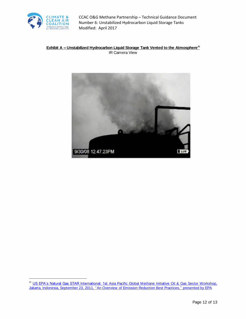
Mitigation Option A – Recover the tank vapors by installing a VRU system and directing to productive use (e.g., fuel gas, compressor suction, gas lift). One way to reduce emissions of tank vapors is to install vapor recovery units (VRUs) on storage tanks. A VRU first draws hydrocarbon vapors out of a fixed roof storage tank under low pressure, typically between 4 ounces and 2 psi (0.0175 and 0.14 kg/cm2) gauge pressure, and routes them through a separator (suction scrubber) to a specifically designed wet gas compressor. Proper design includes routing the suction line with only a downward slope to the suction scrubber so that a liquid trap does not occur that would inhibit
8 EPA. Greenhouse Gas Reporting Program, Subpart W – Petroleum and Natural Gas Systems. Section 98.233: Calculating GHG emissions. 40 CFR 98.233(j)(8). http://www.ecfr.gov/cgi-bin/text-idx?SID=9db68a97576bb01eea9073c37d6f0e90&node=40:21.0.1.1.3.23&rgn=div6.

CCAC O&G Methane Partnership – Technical Guidance Document Number 6: Unstabilized Hydrocarbon Liquid Storage Tanks Modified: April 2017
Page 7 of 13
free flow of gas to the compressor. From the compressor, the vapors are routed to their desired location(s) within the facility: a gas sales line, local fuel, and/or suction of a production or gas lift compressor. The liquids from a separator can be returned to the oil storage tank or collected separately and sold to a processing plant or refinery for a premium price. The recovered vapors are rich in propane, butanes, and natural gasoline and will therefore have higher heat content and a higher value to gas processing plants than pipeline quality natural gas. Operational Considerations Virtually any tank battery is a potential site for a VRU. Two indicators of a potential VRU project are a regular and sufficient quantity of crude oil and/or condensate production and an economic outlet for collected products. Note that a source of electricity is highly desired to power several of the VRU’s components. Included in a standard VRU are:
Sloping downward suction pipeline manifolded to all tanks.
Suction scrubber (separator).
Compressor (typically electric-driven rotary vane, screw, or scroll compressor).
Liquid transfer pump.
Electronic Programmable Logic Controller (PLC).
Associated discharge piping, instruments, valves, and controls. Periodic, large flow of liquids out of the storage tanks during pump-out can cause large and rapid fluctuations in tank pressure, putting stress on the VRU. Partners may consider installing a vapor recovery tower (VRT) to ensure the VRU operates at steady state within its design capacity even with the rapid changes in pressure with liquids flow out of the storage tank(s). This is an inexpensive way to elevate the crude oil or condensate gas/oil separation and flash gas generation above the tank to isolate the vapor recovery from tank liquid movements. Working and standing losses are minimal from low vapor pressure oil gravity draining into the tank. Wet screw compressors are often chosen for VRU applications for their ability to achieve high compression ratios (up to 20 in a single stage)9 due to the injection of a significant amount of coolant into the compressor chamber. While this coolant injection lowers gas discharge temperature and improves compressor efficiency, the volume increase caused by the coolant decreases the effective volume for gas. Partners should model screw compressor performance using both factors. The optimal adiabatic efficiency for a single stage screw compressor is achieved at approximately a 3:1 pressure ratio,10 although higher pressure ratios are achievable without sacrificing significant efficiency, given suitable discharge temperature and motor limitations (typical motor operates at 3600 rpm). Methane Emission Reduction Estimate Ideally, in the correct operating condition, VRUs can recover nearly all vapors from a storage tank. Based on a VRU operating factor of 95 percent (allowing 5 percent yearly downtime of the VRU for maintenance), Partners can expect to reduce methane emissions from a storage tank by 95 percent after implementing this technology.
9 Hanlon, Paul C. Compressor Handbook. 2001. Section 2.3.2. 10 Hanlon, Paul C. Compressor Handbook. 2001. Section 14.6.

CCAC O&G Methane Partnership – Technical Guidance Document Number 6: Unstabilized Hydrocarbon Liquid Storage Tanks Modified: April 2017
Page 8 of 13
Economic Considerations The cost of a VRU is dependent on several design/operational factors, including gas throughput to the VRU, inlet and desired outlet temperatures and pressures for the system, and composition(s) of the gas being recovered. Partners should size a VRU to handle the maximum volume of vapors expected from the storage tanks (a rule of thumb is to double the average daily volume). Partners should optimize VRU design and cost to maximize emission capture and minimize costs, for example by routing emissions from several tanks to a single VRU. In considering VRU sizing, Partners should consider production forward planning, so that the VRU can handle planned increased production to the tank battery. Also, a VRU can recover other vented or flared gas streams at a facility. This would enable Partners to capture these additional gas streams that are currently being lost to the atmosphere and can improve a proposed project’s economics. Partners would need to account for the maximum throughputs associated with these gas streams in the initial VRU design. Examples include pneumatic device vents, compressor rod packing vents, Glycol Dehydrator vent (with a vent condenser), and controlled equipment blowdowns. Estimated VRU and associated installation costs for 25 thousand cubic feet per day (Mcf/day) and 500 Mcf/day throughputs (708 standard cubic meters per/day and 14,158 scm/day) are approximately $35,000 and $105,000, respectively.11,12 Partner and VRU manufacture experience has shown that installation costs range between 50 to 100 percent of the initial VRU equipment cost (75 percent was chosen for economic estimates provided here). Yearly operation (primarily electricity) and maintenance costs (O&M) associated with these VRU capacities are $7,400 and $16,800, respectively.13 Note that the VRU costs provided are for recovery of hydrocarbon vapors at atmospheric pressure and approximately 70 °F (21 °C) for discharge into a typical sales gas line up to approximately 100 psig pressure and 212 °F (100 °C) temperature. Discharging gas at pressures above 100 psig (7 kg/cm2) will likely involve a two-stage compressor. Note that installation costs can vary widely depending primarily on the location of a site (VRU installation at remote sites will likely incur higher costs) and number of tanks being connected to the VRU system. O&M costs vary depending on the location of the VRU system (VRUs installed in a cold climate experience more wear), the quality of the gas (high acid content, CO2 and/or H2S have higher corrosion rates), electricity costs, and oil produced (paraffinic oil can clog VRUs more frequently and therefore require increased maintenance).14 Gas value savings associated with installing a VRU take into account recovered high BTU gas and the value of the recovered NGLs in the tank vapors. In most vapor recovery applications, the value of the recovered gas stream is rarely due to the value of methane alone as most tank vapors contain varying amounts of ethane, propane, butane, pentanes, and other “heavy” hydrocarbons. For those Partners that have a gas sales contract that is based upon the heating value (BTU content) of the gas, “wet gas” may sell for upwards of 2.5 times an equivalent volume of pipeline quality natural gas.
11 EPA. Natural Gas STAR Lessons Learned: Installing Vapor Recovery Units on Storage Tanks. June 2016. https://www.epa.gov/sites/production/files/2016-06/documents/ll_final_vap.pdf. 12 Assuming typical gas inlet temperature of 21 °C and sales lines discharge pressure of roughly 7 bar. Installation costs estimated at 75 percent of VRU capital costs. 13 The majority of electricity costs will be for powering the compressor motor. Partners can calculate an estimate of required electricity with knowledge of kWh electricity price and kWh motor consumption. 14 EPA’s Natural Gas Star Lessons Learned: Installing Vapor Recovery Units on Storage Tanks. June 2016. https://www.epa.gov/sites/production/files/2016-06/documents/ll_final_vap.pdf.
CCAC O&G Methane Partnership – Technical Guidance Document Number 6: Unstabilized Hydrocarbon Liquid Storage Tanks Modified: April 2017
Page 9 of 13
For reference, using E&P TANKS software, for a tank holding a medium crude (30° API) at atmospheric pressure and 70° F (21 °C), the mole composition of vapors is approximately 68 percent methane, 10 percent ethane, 8 percent propane, and 3 percent each butane and isobutene. Based on these compositions, for VRU capacities of 25 Mcf/day and 500 Mcf/day (708 scm/day and 14,158 scm/day), the yearly values of these recovered gas streams12, 15 are approximately $30,000 and $600,000 at $7/Mcf of rich tank vapors, respectively. For Partners who have access to natural gas liquid plants, tank vapors could provide a source to feed these plants. For the same mole composition references above and vapor flow rates of 25 Mcf/day and 500 Mcf/day (708 scm/day and 14,158 scm/day), the approximate values of recoverable NGLs (C2 to C4) are $60,000/year and $340,000/year, respectively.16 For more information, see Natural Gas STAR technical document “Installing Vapor Recovery Units on Storage Tanks” (https://www.epa.gov/sites/production/files/2016-06/documents/ll_final_vap.pdf). Mitigation Option B – Install stabilization towers ahead of tanks to reduce the amount of entrained gas and flash gas emitted from the tank(s). In petroleum and gas production facilities, the primary purpose of stabilization towers is to obtain a low oil vapor pressure suitable for loading onto ships and barges or extract more high-value natural gas liquids for gas processing. In gas processing facilities, the purpose of stabilization towers is to separate heavier hydrocarbons and lighter fractions (C1 to C4) prior to transporting and storing crude oil and condensate. In either case, the process separates the lightest liquid component (pentane) and heaviest gas component (butane) through distillation.17 Stabilization towers installed ahead of crude oil storage tanks can serve a similar function as vapor recovery units in reducing methane emissions from storage tanks, with the additional feature that they can reduce the crude oil vapor pressure below atmospheric pressure. Stabilization removes virtually all methane from the crude oil or condensate. Crude oil or condensate enters the top of stabilization towers and flows down a series of trays. When pressurized oil enters the low-pressure column, flashed vapors exit the top of the tower while “stabilized” crude oil or condensate passes through the bottom of the tower(s) and into storage. Adding a reboiler on the bottom of the column creates vapor traffic up the tower to strip more light hydrocarbons out of the oil, and reduces the vapor pressure on the crude product below atmospheric. In addition to the heated reboiler, a stripping gas such as steam may be added near the bottom of the column to provide increased vapor flow and enhance light hydrocarbon (C1 to C4) removal. Given the utility of stabilization towers, some Partners already have them installed and functioning. This technology is considered “mitigated” for methane with regards to liquid petroleum product storage tanks. The possible outlets for the recovered gas from stabilization towers include being sent to a gas processing facility, a fuel gas line, a VRU, and/or combustion in a flare. Because stabilization towers are expensive and installed for the specific purposes listed above, it is not anticipated that Partners will install them as a retrofit for the sole purpose of controlling methane emissions from tanks.
15 NGL values obtained from EPA presentation: Vapor Recovery Tower/VRU Configuration: Lessons Learned from Natural Gas
STAR. August 2007. NGL values extrapolated based on methane value of $3/MMBTU. https://www.epa.gov/natural-gas-star-program/natural-gas-star-outreach-and-events#tab-2. 16 2007 Cost Basis obtained from EPA presentation: Vapor Recovery Tower/VRU Configuration: Lessons Learned from Natural
Gas STAR. August 2007. https://www.epa.gov/natural-gas-star-program/natural-gas-star-outreach-and-events#tab-2. 17 Mokhatab, Saeid., Poe, James A., and Speight, James G. Handbook of Natural Gas Transmission and Processing. Page 249.

CCAC O&G Methane Partnership – Technical Guidance Document Number 6: Unstabilized Hydrocarbon Liquid Storage Tanks Modified: April 2017
Page 10 of 13
Mitigation Option C – Route the tank vapors to a flare/combustion device. Routing storage tank vapors to a flare/combustion device reduces methane emissions to the atmosphere through oxidative combustion of methane. A flare may continuously receive vent streams from one or several processes and/or pieces of equipment at a facility. Operational Considerations Virtually any vented storage tank’s vapors with minimal sulfur content can be routed to an existing flare by installing piping which route the vapors to the flare. It is absolutely essential to include a flame arrestor in the flare line near the tank as air drawn into an atmospheric pressure storage tank can form explosive mixtures that could flash-back from the flare flame and explode the tank. If routing to an existing flare is operationally infeasible, a new flare system requires installation of the following equipment:
Flare stack.
Associated piping used to direct vapors from storage tank(s) to the flare.
Flame arrestor. Gas-fired flares may have one or more continuously burning pilot flames or be ignited with an electric spark-ignition system. Methane Emission Reduction Estimate Companies can expect to achieve a 98 percent reduction in methane emissions from routing storage tank vapors to a flare, assuming a properly operated flare (98 percent combustion efficiency).18 Economic Considerations Minimal capital costs are associated with routing storage tank vapors to an existing flare. These costs include all piping connections and labor required to route vapors from the tank vent(s) to the flare gas line. For a new flare system, estimated total capital investment for a new flare and flame arrestor, including an auto-igniter, and associated freighting, design, and installation is estimated to be $24,300.19 Annual costs are estimated to be approximately $1,800/year for pilot fuel (assuming $3/Mcf) and flare system maintenance. Though flaring achieves no economic benefit in terms of gas saved, a flare is an important operational/safety device at a natural gas/oil installation as it can serve as a safe gas disposal outlet for over-pressurized equipment as well as a gas outlet for equipment undergoing maintenance and repairs, thus reducing methane emissions from these sources by combusting the gas. In addition, flaring the tank vapors means that there is less risk of exposure to harmful pollutants for the operators onsite. For more information, see:
EPA Natural Gas STAR Partner Reported Opportunity Fact Sheet No. 903, “Install Electronic Flare Ignition Devices” (https://www.epa.gov/sites/production/files/2016-06/documents/installelectronicflareignitiondevices.pdf ).
18 EPA. AP 42, Fifth Edition, Volume I. Chapter 13, Section 5: Industrial Flares. 19 EPA. Partner Report Opportunities Fact Sheet No. 904: Install Flares. https://www.epa.gov/sites/production/files/2016-06/documents/installflares.pdf (Price of flame arrestor estimated at $3,000).

CCAC O&G Methane Partnership – Technical Guidance Document Number 6: Unstabilized Hydrocarbon Liquid Storage Tanks Modified: April 2017
Page 11 of 13
EPA Natural Gas STAR Partner Reported Opportunity Fact Sheet No. 904, “Install Flares” (https://www.epa.gov/sites/production/files/2016-06/documents/installflares.pdf).
CCAC O&G Methane Partnership – Technical Guidance Document Number 6: Unstabilized Hydrocarbon Liquid Storage Tanks Modified: April 2017
Page 12 of 13
Exhibit A ---- Unstabilized Hydrocarbon Liquid Storage Tank Vented to the Atmosphere20
IR Camera View
20 US EPA’s Natural Gas STAR International: 1st Asia Pacific Global Methane Initiative Oil & Gas Sector Workshop,
Jakarta, Indonesia, September 23, 2011, ‘‘An Overview of Emission Reduction Best Practices,’’ presented by EPA

CCAC O&G Methane Partnership – Technical Guidance Document Number 6: Unstabilized Hydrocarbon Liquid Storage Tanks Modified: April 2017
Page 13 of 13
Exhibit B ---- Unstabilized Hydrocarbon Liquid Storage Tank with Vapor Recovery Unit 21
21 Natural Gas STAR Producers and Processors Workshop, Billings, Montana, August 31, 2009: ‘‘Installing Vapor
Recovery Units,’’ presentation by EPA
Crude Oil
Stock
Tank(s)
Control
Pilot
Vent Line
Back Pressure
Valve
Suction
Scrubber
Suction
Line
Condensate
Return
Bypass
Valve
Electric
Control
Panel
Electric Driven
Rotary Compressor
Gas Sales
Meter Run
Gas
Liquid
Transfer Pump
Check Valve
Source: Evans & Nelson (1968)
Sales