ecg simulator and 6v to 12v dc to dc
TRANSCRIPT
8/9/2019 ECG Simulator and 6V to 12V DC to DC
http://slidepdf.com/reader/full/ecg-simulator-and-6v-to-12v-dc-to-dc 1/11
6V to 12V dc-dc boost converter using 555 timer IC
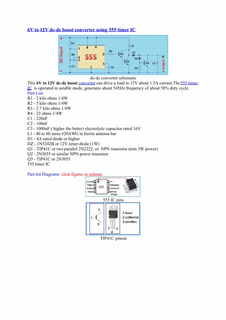
dc-dc converter schematicThis 6V to 12V dc-dc boost converter can drive a load in 12V about 1.5A current.The 555 timerIC is operated in astable mode, generates about 545! "re#uenc$ o" about 5%& dut$ c$cle .'art (ist)*1 - 2 +ilo ohms 14*2 - 5 +ilo ohms 14* - 2./ +ilo ohms 14
*4 - 22 ohms 14C1 - 220nC2 - 100nC - 1000u higher the better3 electrol$tic capacitor rated 1V(1 - 40 to 0 turns 20A6 in "errite antenna bar 71 - 4A rated diode or higher 78 - 195242: or 12V !ener diode 13;1 - TI'41C or t<o parallel 292222, or 9'9 transistor min po<er3;2 - 29055 or similar 9'9 po<er transistor ; - TI'41C or 29055555 timer IC
'art list 7iagrams) clic+ "igures to enlarge
555 IC pins
TI'41C pinout

8/9/2019 ECG Simulator and 6V to 12V DC to DC
http://slidepdf.com/reader/full/ecg-simulator-and-6v-to-12v-dc-to-dc 2/11
292222 pinout
29055 pinout
<indings in antenna "errite rod
=n>o$ building this converter and "eel "ree to replace an$ parts. ?ou can add also series resistorand (=7 across the output o" the circuit "or indicator.
*ead more at http)<<<.simple-electronics.com200@0@555-timer-pro>ect--12v-dc-dc- boost.html0#?r0=%V%!Bll.@@

8/9/2019 ECG Simulator and 6V to 12V DC to DC
http://slidepdf.com/reader/full/ecg-simulator-and-6v-to-12v-dc-to-dc 3/11
7o-it-$oursel"
=C6'atientimulator A lo<-cost solution
created b$ ran+ eithner
Dne o" the most important test e#uipment in the biomedical <or+shop is the =C6 Tester or'atient imulator. The 'atient imulator is connected to the =C6 monitor and delivers thet$pical =C6 signal. Dnl$ <ith such a tester an =C6 monitor can be repaired, the "unctions andalarm settings chec+ed and loose connections o" the patient cables be located. A 'atientimulators usuall$ costs several hundred dollars and is una""ordable "or small hospital <or+shopspeciall$ in developing countries.:ut the reali!ation o" an electronic circuit <hich creates an =C6 signal must not be too di""icultand eEpensive. ere I <ant to introduce $ou m$ solution. Dnl$ a hand"ul cheap electronicdevices are used. 9o special or eEotic IC is needed. All parts should be available in the nearest
electronic shop or can be "ound on old electronic boards "rom $our <or+shop store.This circuit consist o" a hand"ul electronic devices <hich delivers a #uart! cr$stal stable =C6signal "or 0 and 120 heart beats. Dnl$ common electronic parts are needed and the buildingcosts are belo< 20 F.
unction)
The above sho<n =C6 signal is compleE and <ill be created b$ di""erent single signals. The',;,*,,T signals are "ormed in di""erent steps and then are put together in the right se#uence. A

8/9/2019 ECG Simulator and 6V to 12V DC to DC
http://slidepdf.com/reader/full/ecg-simulator-and-6v-to-12v-dc-to-dc 4/11
shi"t register does the se#uence >ob, *C combinations the "re#uenc$ and amplitude o" the single<aves.IC1 contains an oscillator and a shi"t register. At the output o" pin10 a signal <ith 1 ! triggersIC2. IC2 is a counter <ith 10 outputs. hen output 0 o" IC2 is active pin3 the *-C combination*%, C5 creates the '-<ave. hen the counter >umps to output pin/3 the *-<ave is created b$
*4, C4. The negative part is reduced b$ the t<o diodes and simulate the "ollo<ing -<ave.hen output 5 is active pin13 the T-<ave is created b$ */ and C5. The outputs <hich are notconnected create the needed pauses bet<een the signals. All signals are put together through *and * <hich level the respective amplitudes.
hen one se#uence is "inished the shi"t register stops. Dutput @ pin113 is connected <ith =9-input pin13. Dnl$ <hen a reset pulse reaches the counter pin153 the counter starts again. Thisreset is also created b$ IC1. :ecause in addition to the 1 ! trigger signal the IC also provides a1 ! and a 0.5 ! signal at pin14 and pin1 <hich correlate a heart beat rate o" 0 and 120s<itch 23. There"ore the s#uare signal has to be trans"ormed in a positive needle pulse. This isthe dut$ o" the combination C, *11, 74, *10. :ecause this pulse comes earlier or later 0.5 !or 1 !3 onl$ the lengths o" the G period is shorter or longer. The ';*T <ave "orm is note""ected.A small (=7 7 <ith resistor *5 connected to output pin/, IC23, "lashes during the
*- period.The "inal resistor combination *12-*15 converts the bipolar signal "rom the electronic boardinto the needed three pole output signal.
9ote) The circuit is designed "or common electronic devices. All parts can be "ound on oldelectronic boards or at the nearest electronic shop. :ut i" $ou have problems to "ind the cloc+-cr$stal o" 4.1@4 H! $ou can ta+e a 4.4 H! 'A(-cr$stal "rom a TV. ?our output signal is asgood as <ith the cloc+-cr$stal but the heart rate <ill change to and 12/ beats per minute.

8/9/2019 ECG Simulator and 6V to 12V DC to DC
http://slidepdf.com/reader/full/ecg-simulator-and-6v-to-12v-dc-to-dc 5/11
large image3 large image3
'art list)
*1 4B/*2, *% 1H*, *4, *@, *10, *11, *12, *1 100B *5 1B *, */ 4/0B *14, *15 220C1 22 pC2 %2 pC, C4, C5, C 220nIC1 4521IC2 401/71, 72, 74 19414%cristal 4.1@4 Hh!7 (=7 mm2 E IC soc+ets 1 pin
ere the "irst design)

8/9/2019 ECG Simulator and 6V to 12V DC to DC
http://slidepdf.com/reader/full/ecg-simulator-and-6v-to-12v-dc-to-dc 6/11
ere the second version)
large image3 large image3
large image3
8/9/2019 ECG Simulator and 6V to 12V DC to DC
http://slidepdf.com/reader/full/ecg-simulator-and-6v-to-12v-dc-to-dc 7/11

8/9/2019 ECG Simulator and 6V to 12V DC to DC
http://slidepdf.com/reader/full/ecg-simulator-and-6v-to-12v-dc-to-dc 8/11

8/9/2019 ECG Simulator and 6V to 12V DC to DC
http://slidepdf.com/reader/full/ecg-simulator-and-6v-to-12v-dc-to-dc 9/11

8/9/2019 ECG Simulator and 6V to 12V DC to DC
http://slidepdf.com/reader/full/ecg-simulator-and-6v-to-12v-dc-to-dc 10/11

8/9/2019 ECG Simulator and 6V to 12V DC to DC
http://slidepdf.com/reader/full/ecg-simulator-and-6v-to-12v-dc-to-dc 11/11