ecen 449 – microprocessor system · pdf file · 2008-01-17– vhdl •...
TRANSCRIPT

1Texas A&M University
ECEN 449 – Microprocessor System Design
Verilog

2Texas A&M University
Objectives of this Lecture Unit
• Get a feel for the basics of Verilog– The focus of this unit will be along two separate but equally relevant
axes• We will cover the semantics of Verilog and different modeling styles• Also we will cover syntax issues. For this portion, additional resources
are also provided on the website.– In general Verilog is quite rich, and therefore, there are many ways to
achieve the same design goal• We will focus on the syntax that is most common, especially from a
synthesizability point of view.

3Texas A&M University
Hardware Description Languages (HDLs)
• What is a HDL, why is it useful• The Verilog HDL• Modelling a simple circuit in Verilog
– Gate level– Dataflow– Procedural– Synthesizable Verilog
• Testbenches• Syntax coverage

4Texas A&M University
Hardware Description Language (HDLs)
• A HDL is a programming language which is tuned to describe hardware
• HDLs allow us to design and simulate a design at a higher level of abstraction – Result = higher designer productivity
• HDLs also have accompanying synthesis tools which allow the designer to obtain an implementation from HDL code.– Further improvement in designer productivity
• FPGA based design flows use HDLs heavily!

5Texas A&M University
Common HDLs
• There are mainly two HDLs in use today– Verilog HDL– VHDL
• VHDL is the somewhat more common– Standard developed by US DoD– VHDL = (Very High Speed Integrated Circuit) HDL
• We choose Verilog for this class because– It is easier to use and teach– Resembles “C” and hence easier to learn.
• Which one is “better”?– This is the topic of much debate
6Texas A&M University
Verilog HDL
• Verilog constructs are use defined keywords– Examples: and, or, wire, input, output
• One important construct is the module– Modules have inputs and outputs – Modules can be built up of Verilog primitives or of user defined
submodules.
7Texas A&M University
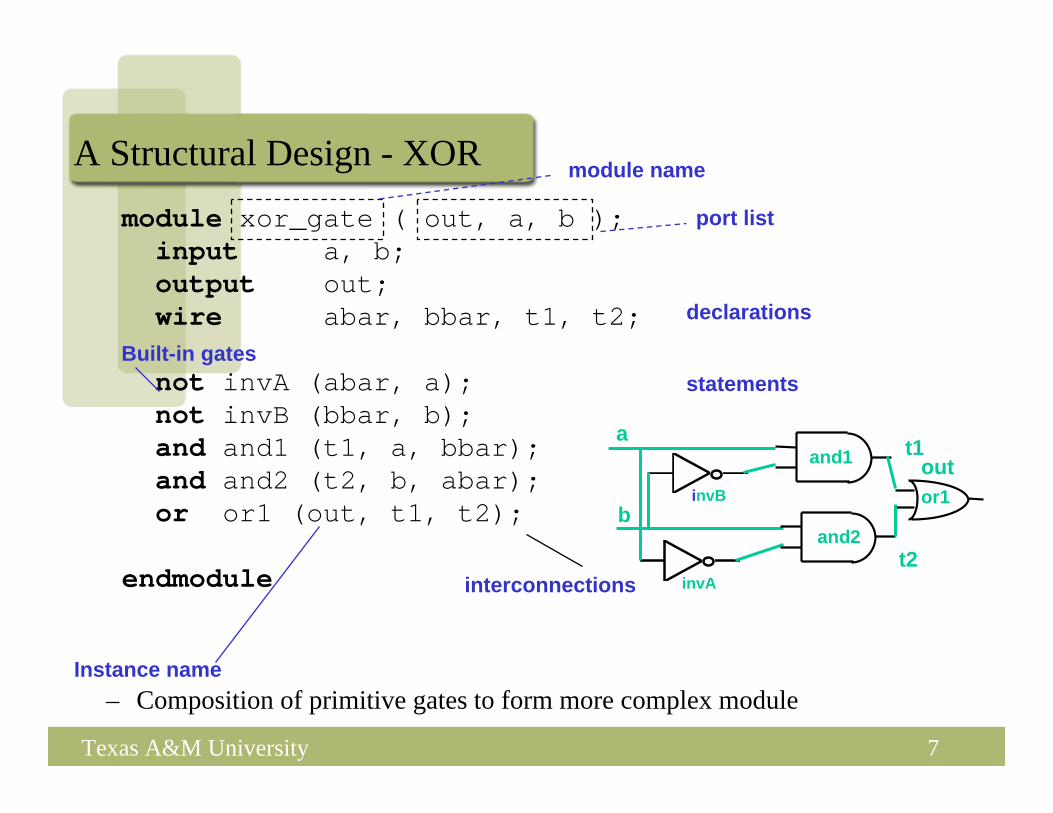
module xor_gate ( out, a, b );input a, b;output out;wire abar, bbar, t1, t2;
not invA (abar, a);not invB (bbar, b);and and1 (t1, a, bbar);and and2 (t2, b, abar);or or1 (out, t1, t2);
endmodule
A Structural Design - XOR
– Composition of primitive gates to form more complex moduleInstance name
port list
module name
declarations
statementsBuilt-in gates
interconnections invA
invB
a
b
outand1
and2
or1
t1
t2

8Texas A&M University
Another Simple Circuit (in Structural Verilog)
module smpl_circuit(A,B,C,x,y);input A,B,C;output x,y;wire e;and g1(e,A,B);not g2(y, C);or g3(x,e,y);
endmodule

9Texas A&M University
Structural Verilog
• Just specifies primitive gates and wires– In other words, the structure of a logical netlist
• Useful if you know exactly what logic you want to generate– Not useful for large designs, where we want to specify the design at a
higher level of abstraction• It is crucial to design at a higher level of abstraction in this case, since
structural design would be tedious and error prone– In such a case, we will describe the circuit at a high level of
abstraction, and let the CAD tools realize the detailed design (by performing the steps of synthesis, mapping, placement+routing, and generation of the netlist (in an FPGA, this is the bitgen file)
– In special cases, delay or area-critical sub-blocks can be designed in structural manner, while the rest of the logic could be at a higher level of abstraction (typically described in the behavioral fashion).

10Texas A&M University
Simple Circuit – Comments
• The module starts with module keyword and finishes with endmodule.
• Internal signals are named with wire.• Comments follow //• input and output are ports. These are placed at the start of the
module definition.• Each statement ends with a semicolon, except endmodule.

11Texas A&M University
Adding Delays
• To simulate a circuit’s real world behaviour it is important that propagation delays are included.
• The units of time for the simulation can be specified with timescale. – Default is 1ns with precision of 100ps
• Component delays are specified as #(delay)• BUT REMEMBER – these delays will NOT synthesize.
– Useful only for simulation and verification of your design.

12Texas A&M University
Simple Circuit with Delaymodulecircuit_with_delay (A,B,C,x,y);
input A,B,C;
output x,y;
wire e;
and #(30) g1(e,A,B);
or #(20) g3(x,e,y);
not #(10) g2(y,C);
endmodule0 1 11 1 150
0 1 01 1 140
0 1 01 1 130
0 0 11 1 120
0 0 11 1 110
1 0 11 1 10
1 0 10 0 00
Outputy e x
InputA B C
Time(ns)

13Texas A&M University
Structural Model
• Built-in gate primitives:and, nand, nor, or, xor, xnor, buf, not, bufif0, bufif1, notif0, notif1
• Usage:nand (out, in1, in2); 2-input NAND without delayand #2 (out, in1, in2, in3); 3-input AND with 2 t.u. delaynot #1 N1(out, in); NOT with 1 t.u. delay and instance namexor X1(out, in1, in2); 2-input XOR with instance name
14Texas A&M University
Dataflow modelling
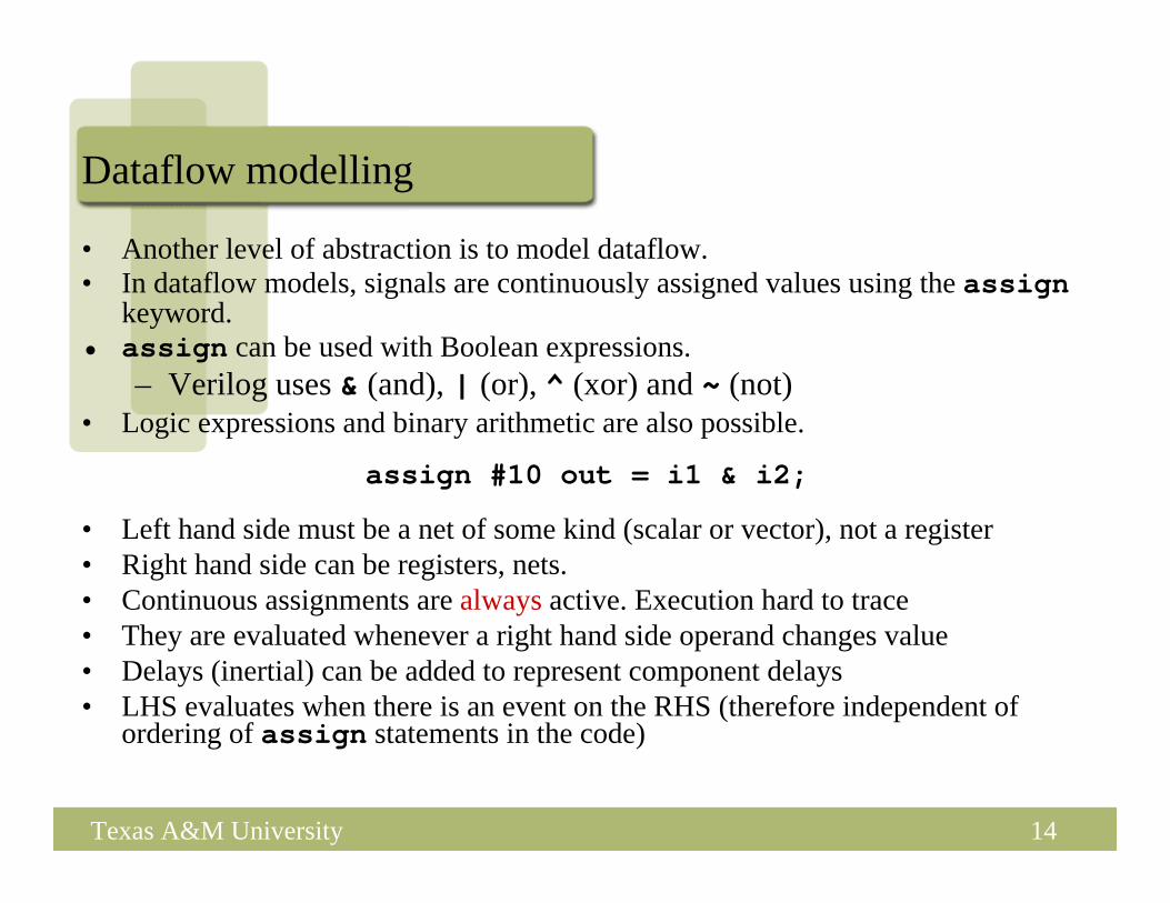
• Another level of abstraction is to model dataflow.• In dataflow models, signals are continuously assigned values using the assign
keyword.• assign can be used with Boolean expressions.
– Verilog uses & (and), | (or), ^ (xor) and ~ (not)• Logic expressions and binary arithmetic are also possible.
• Left hand side must be a net of some kind (scalar or vector), not a register• Right hand side can be registers, nets.• Continuous assignments are always active. Execution hard to trace• They are evaluated whenever a right hand side operand changes value• Delays (inertial) can be added to represent component delays• LHS evaluates when there is an event on the RHS (therefore independent of
ordering of assign statements in the code)
assign #10 out = i1 & i2;

15Texas A&M University
Simple Circuit Boolean Expression
x = A.B + C
y = C

16Texas A&M University
Dataflow Description of Simple Circuit//Circuit specified with Boolean equations
module circuit_bln (x,y,A,B,C);
input A,B,C;
output x,y;
assign x = (A & B) | ~C;
assign y = ~C ;
endmodule
Order does notmatter!

17Texas A&M University
Multiplexor
• Multiplexor is a combinational circuit where an input is chosen by a select signal.– Two input mux – output =A if select =1– output= B if select =0
AB x
s

18Texas A&M University
Dataflow description of 2-input Mux
• Conditional operator ?:takes three operands:condition? true_expression : false_expression
module mux2x1_df (A,B,select,OUT);input A,B,select;output OUT;assign OUT = select ? A : B;
endmodule

19Texas A&M University
Behavioural Modelling
• Represents circuits at functional and algorithmic level.• Use procedural statements similar in concept to procedural
programming languages (e.g. C, Java),• Behavioural modelling is mostly used to represent sequential
circuits.• We still specify a module in Verilog with inputs and outputs...
– But inside the module we write code to specify the behavior we want, NOT what gates (structure) to connect to make it happen
• Why use behavioral models– For high-level specs to drive logic synthesis tools
20Texas A&M University
Behavioural Modelling
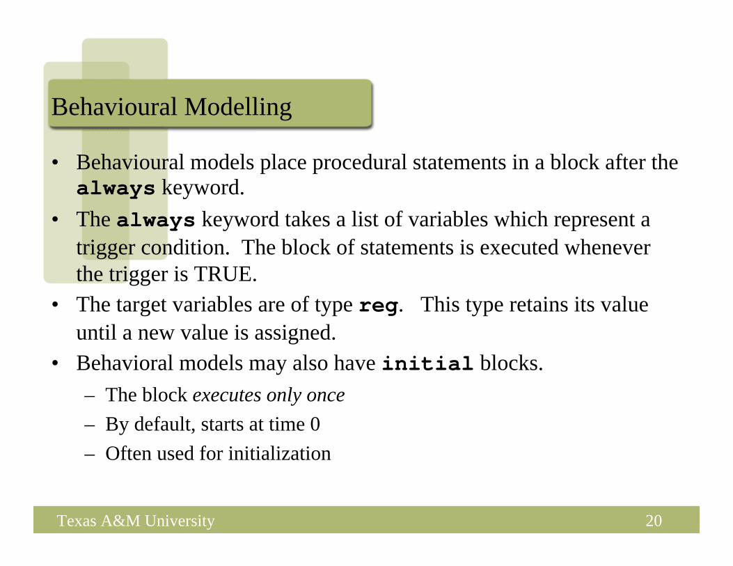
• Behavioural models place procedural statements in a block after the always keyword.
• The always keyword takes a list of variables which represent a trigger condition. The block of statements is executed wheneverthe trigger is TRUE.
• The target variables are of type reg. This type retains its value until a new value is assigned.
• Behavioral models may also have initial blocks.– The block executes only once– By default, starts at time 0 – Often used for initialization

21Texas A&M University
Always Blocks• Module may have any number of always blocks• Allow us to represent parallelism in hardware.

22Texas A&M University
Behavioral Description of an XOR
module xorB(X, Y, Z);input X, Y;output Z;reg Z;always @ (X or Y)
Z = X ^ Y;endmodule
• Unusual parts of above Verilog– “always @ (X or Y)” => whenever X or Y changes, do
the following statement– “reg” is only type of behavioral data that can be changed in
assignment, so must redeclare Z– Default is single bit data types: X, Y, Z

23Texas A&M University
Behavioural description of 2-input Mux
module mux2x1_bh(A,B,select,OUT);input A,B,select;output OUT;reg OUT; always @ (select or A or B)
if (select == 1) OUT = A;else OUT = B;
endmodule
24Texas A&M University
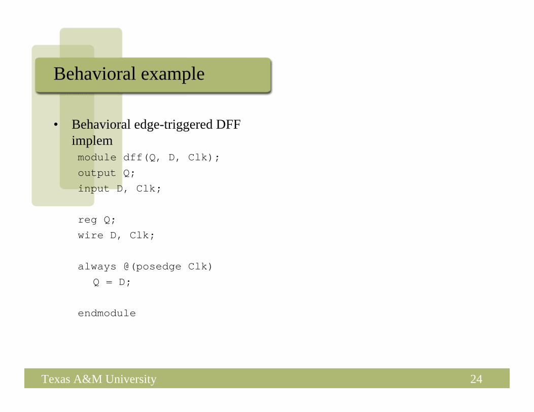
Behavioral example
• Behavioral edge-triggered DFF implemmodule dff(Q, D, Clk);output Q;
input D, Clk;
reg Q;wire D, Clk;
always @(posedge Clk)Q = D;
endmodule

25Texas A&M University
Another Behavioral Example
ab
c
Y
W
clk
resalways @(res or posedge clk) begin
if (res) beginY = 0;W = 0;end
else beginY = a & b;W = ~c;end
end

26Texas A&M University
• Represented with an = sign– All blocking assignments are executed in sequence
Blocking Assignments
module dummy;reg x, y, z;reg [15:0] reg_a, reg_b;integer count;initialbegin
x = 0; y = 1; z = 1;count = 0;reg_a = 16'b0; reg_b = reg_a;reg_a[2] = #15 1;reg_b[15:13] = #10 {x, y, z};count = count + 1;
end

27Texas A&M University
• Represented with a <= sign– All non-blocking assignments are executed in parallel– Try not to mix with blocking assignments
Non-blocking Assignments
module dummy;reg x, y, z;reg [15:0] reg_a, reg_b;integer count;initialbegin
x = 0; y = 1; z = 1;count = 0;reg_a[2] <= #15 1;reg_b[15:13] <= #10 {x, y, z};count = count + 1;
end

28Texas A&M University
Blocking or Non-blocking???
• Blocking is harder to reason about. • Also hardware does not work in a blocking (sequential way)• So generally you should use non-blocking assignments
– Easier to synthesize– Models parallelism which is inherent in the hardware

29Texas A&M University
• Inertial Delay – consider the statement
assign #4 x = z;
– It’s delay behavior is called “inertial”delay
– Applicable for gate level primitives and continuous assignments
• Transport delay – consider the statement
always @(z)y <= #4 z;
– Its delay is called “transport” delay– Applicable in non-blocking
assignments
Two kinds of Delays in Verilog
0 9 10 19
4 23
z
x
4 13 14 23y

30Texas A&M University
Delving Deeper
• So far, we saw how some sample circuits are represented in the three styles
• In the next part of this lecture unit, we will talk about– Logic values in Verilog– How to represent hierarchical designs– Testbenches– How to represent sequential logic– Synthesizability Tips– Syntax examples (will not go over in class in any detail, this portion
of the notes is for your reference)
31Texas A&M University
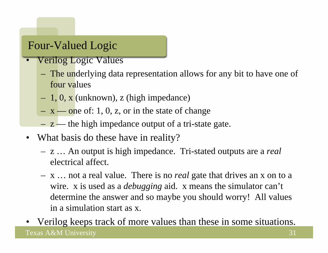
Four-Valued Logic• Verilog Logic Values
– The underlying data representation allows for any bit to have one of four values
– 1, 0, x (unknown), z (high impedance)– x — one of: 1, 0, z, or in the state of change– z — the high impedance output of a tri-state gate.
• What basis do these have in reality?– z … An output is high impedance. Tri-stated outputs are a real
electrical affect.– x … not a real value. There is no real gate that drives an x on to a
wire. x is used as a debugging aid. x means the simulator can’t determine the answer and so maybe you should worry! All values in a simulation start as x.
• Verilog keeps track of more values than these in some situations.
32Texas A&M University
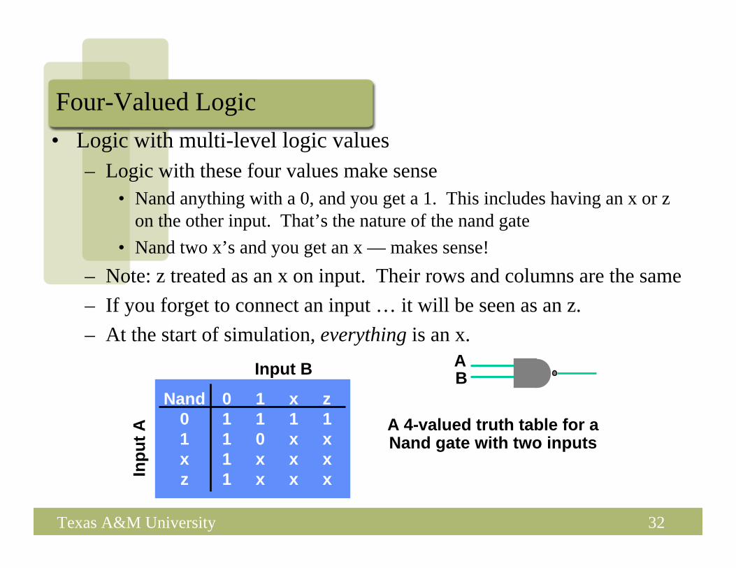
Four-Valued Logic• Logic with multi-level logic values
– Logic with these four values make sense• Nand anything with a 0, and you get a 1. This includes having an x or z
on the other input. That’s the nature of the nand gate• Nand two x’s and you get an x — makes sense!
– Note: z treated as an x on input. Their rows and columns are the same– If you forget to connect an input … it will be seen as an z.– At the start of simulation, everything is an x.
Nand 0 1 x z0 1 1 1 11 1 0 x xx 1 x x xz 1 x x x
A 4-valued truth table for a Nand gate with two inputs
Inpu
t A
Input B AB

33Texas A&M University
How to Represent Hierarchy in your Design
module B1(a, b, c);………………..
endmodulemodule B2(a, b, c, d);
………………..endmodulemodule B3(x, y, z);
………………..endmodule
B1 B2
B3
• First write the modules for each block of the hierarchy– Then wire them up (next page)

34Texas A&M University
Port Mapping (Connecting things up)
module top(a,b,c,d);…….
B1 b1(w, q, a, c);........
endmodule
module B1(q, w, e, f);input q, w;input [3:0] e;output [1:0] f;……………….
endmoduleB1
w q
wqa
c
e
f
Module B1 declared
Module B1 instantiated, instance is called myinstin this case

35Texas A&M University
Example (Dataflow, with hierarchy)
module half_adder(S, C, A, B);output S, C;input A, B;
wire S, C, A, B;
assign S = A ^ B;assign C = A & B;
endmodule
HalfAdderHalf
Adder
A
B
S
C
A
B
S
C
36Texas A&M University
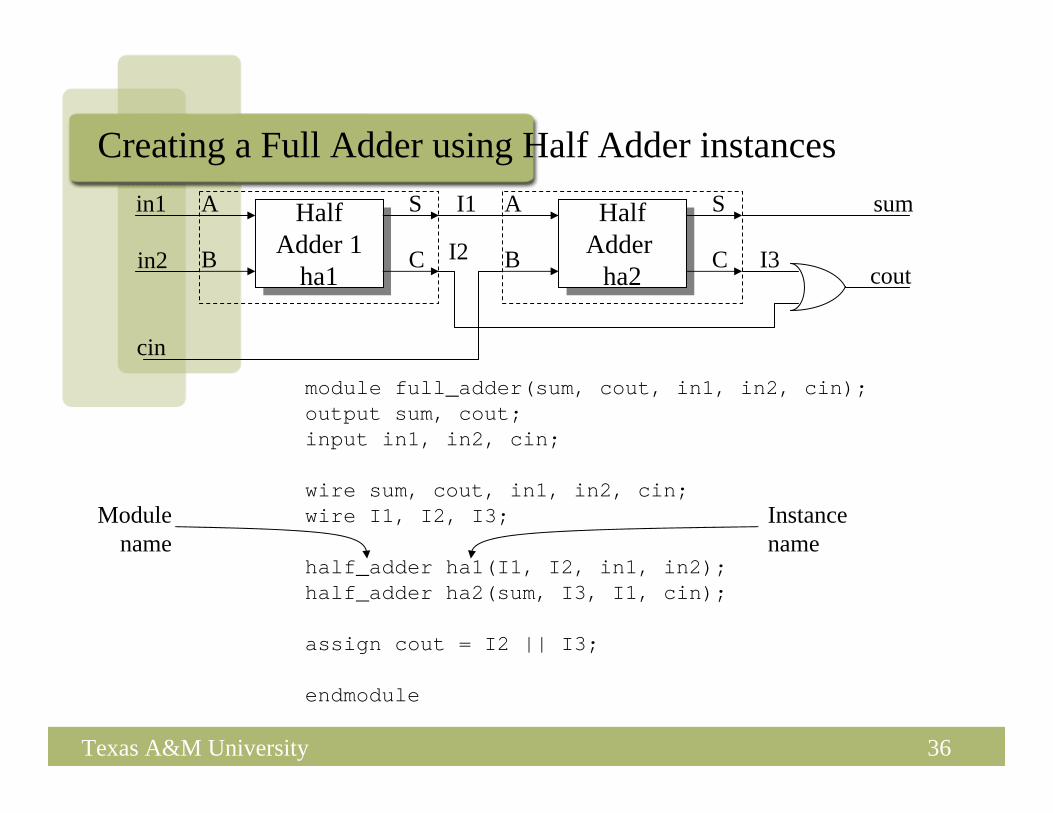
Creating a Full Adder using Half Adder instances
module full_adder(sum, cout, in1, in2, cin);output sum, cout;input in1, in2, cin;
wire sum, cout, in1, in2, cin;wire I1, I2, I3;
half_adder ha1(I1, I2, in1, in2);half_adder ha2(sum, I3, I1, cin);
assign cout = I2 || I3;
endmodule
Instancename
Modulename
HalfAdder
ha2
HalfAdder
ha2
A
B
S
CHalf
Adder 1ha1
HalfAdder 1
ha1
A
B
S
C
in1
in2
cin
cout
sumI1
I2 I3
37Texas A&M University
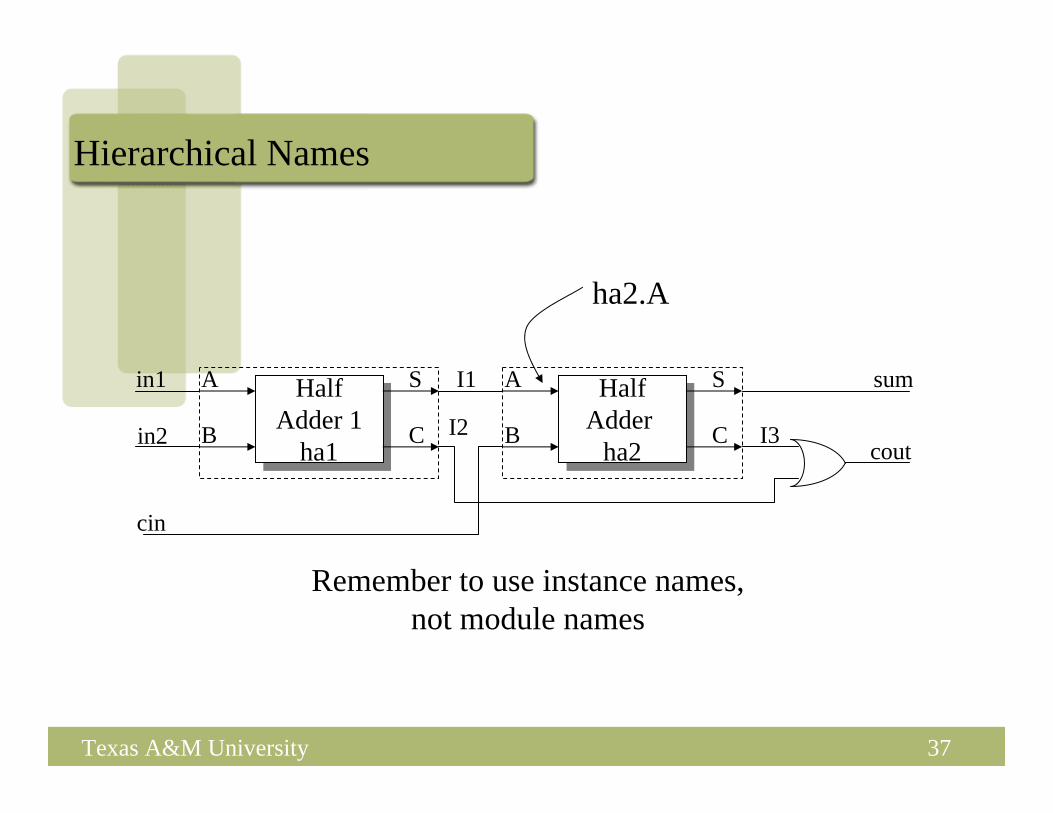
Hierarchical Names
ha2.A
Remember to use instance names,not module names
HalfAdder
ha2
HalfAdder
ha2
A
B
S
CHalf
Adder 1ha1
HalfAdder 1
ha1
A
B
S
C
in1
in2
cin
cout
sumI1
I2 I3

38Texas A&M University
Verification
• Use testbench to verify your design– Special Verilog file for simulating and testing your design– Instantiates the module to be tested– Contains code to apply stimulus to the module under test, and monitor
the correctness of the response
Response&
Verification
Stimulus&
Control SignalTest-Bench
Module under Test

39Texas A&M University
Sample Testbenchmodule top_test;wire [1:0] t_out; // Top’s signalsreg [3:0] t_in;reg clk;
top inst(t_out, t_in, clk); // Top’s instance
initial begin // Generate clockclk = 0;forever #10 clk = ~clk;
end
initial begin // Generate remaining inputs$monitor($time, " %b -> %b", t_in, t_out);#5 t_in = 4'b0101;#20 t_in = 4'b1110;#20 t_in[0] = 1;#300 $finish;
end
endmodule

40Texas A&M University
//Parallel to Serial converter
module ParToSer(LD, X, out, CLK); input [3:0] X;
input LD, CLK;output out; reg out;
reg [3:0] Q;assign out = Q[0];
always @ (posedge CLK)if (LD) Q=X;else Q = Q>>1;
endmodule // mux2
module FF (CLK,Q,D);input D, CLK;
output Q; reg Q;always @ (posedge CLK) Q=D;
endmodule // FF
Sequential Logic
• Notes:– “always @ (posedge CLK)” forces Q
register to be rewritten every simulation cycle.
– “>>” operator does right shift (shifts in a zero on the left).
– Shifts on non-reg variables can be done with concatenation:wire [3:0] A, B;
assign B = {1’b0, A[3:1]}

41Texas A&M University
Sequential Logic – another examplemodule mealy (A, CLK, Z);
input A, CLK;output Z;reg Z;
always @(posedge CLK) Pstate = Nstate; // synchronous partalways @(Pstate or A) begin: COMBINPART
case (Pstate)ST0:if(A)begin
Z=1;Nstate = ST3;
endelse
Z=0;
ST1:if(A)
beginZ=0;Nstate = ST2;
endelse
Z=0;<ETC><ETC>
endcaseend
endmodule
• Notes:– If we have a state machine updating
on a rising clock edge, then we create the always block (triggered on the posedge of clock).
– Also we write the state machine behavior as a case statement.
• For example if we are in state ST0, and A is 1, then we move to state ST3 in the next clock.
– This kind of code for a state machine is very similar to the state transition diagram based behavior. Hence easy to write.

42Texas A&M University
Synthesizability Tips
• If you want to synthesize your Verilog code, here are some tips– Do not use delays in your code– Watch for blocking and non-blocking assignments (next slide)– Watch out for complete assignments (2 slides after next)

43Texas A&M University
Blocking and Non-blocking
44Texas A&M University
“Complete” Assignments
• If an always block executes, and a variable is not assigned– Variable keeps its old value (this needs state!!)– Hence latch is inserted (inferred memory)– This is usually not what you want: dangerous for the novice!
• So to aviod this, any variable assigned in an always block should be assigned for any (and every!) execution of the block

45Texas A&M University
module and_gate (out, in1, in2);input in1, in2;output out;reg out;
always @(in1) beginout = in1 & in2;
end
endmodule
Incomplete Triggers
• Leaving out an input trigger usually results in a sequential circuit• Example: The output of this “and” gate depends on the input
history (a latch will be inferred on in2).
46Texas A&M University
Some Verilog Syntax Notes for Your Reference..
• You may find the following slides handy as a partial Verilog reference. – It is not meant to be a complete reference – see the resources on the
class website for more detailed references.– It is meant to help you with the syntax for common Verilog
constructs.

47Texas A&M University
User Identifiers
• Formed from {[A-Z], [a-z], [0-9], _, $}, but .. • .. can’t begin with $ or [0-9]
– myidentifier
– m_y_identifier
– 3my_identifier
– $my_identifier
– _myidentifier$
• Case sensitivity– myid ≠ Myid

48Texas A&M University
Comments
• // The rest of the line is a comment
• /* Multiple linecomment */
• /* Nesting /* comments */ do NOT work */

49Texas A&M University
Numbers in Verilog (i)
<size>’<radix> <value>
– 8’h ax = 1010xxxx– 12’o 3zx7 = 011zzzxxx111
No of bits
No of bits
Binary → b or BOctal → o or ODecimal → d or DHexadecimal → h or H
Binary → b or BOctal → o or ODecimal → d or DHexadecimal → h or H
Consecutive chars 0-f, x, z
Consecutive chars 0-f, x, z

50Texas A&M University
Numbers in Verilog (ii)
• You can insert “_” for readability– 12’b 000_111_010_100 – 12’b 000111010100– 12’o 07_24
• Bit extension– MS bit = 0, x or z ⇒ extend this
• 4’b x1 = 4’b xx_x1– MS bit = 1 ⇒ zero extension
• 4’b 1x = 4’b 00_1x
Represent the same number

51Texas A&M University
Numbers in Verilog (iii)
• If size is ommitted it – is inferred from the value or– takes the simulation specific number of bits or– takes the machine specific number of bits
• If radix is ommitted too .. decimal is assumed– 15 = <size>’d 15

52Texas A&M University
Nets (i)
• Can be thought as hardware wires driven by logic• Equal z when unconnected• Various types of nets
– wire
– wand (wired-AND)– wor (wired-OR)– tri (tri-state)
• In following examples: Y is evaluated, automatically, every time A or B changes

53Texas A&M University
Nets (ii)
AB Y
wire Y; // declaration
assign Y = A & B;
B
AY
wand Y; // declaration
assign Y = A;assign Y = B;
wor Y; // declaration
assign Y = A;assign Y = B;
A Ydr
tri Y; // declaration
assign Y = (dr) ? A : z;

54Texas A&M University
Registers• Variables that store values• Do not represent real hardware but ..• .. real hardware can be implemented with registers• Only one type: reg
reg A, C; // declaration// assignments are always done inside a procedureA = 1;
C = A; // C gets the logical value 1A = 0; // C is still 1C = 0; // C is now 0
• Register values are updated explicitly!!

55Texas A&M University
Vectors• Represent buses
wire [3:0] busA;
reg [1:4] busB; reg [1:0] busC;
• Left number is MS bit• Slice management
busC[1] = busA[2];
busC[0] = busA[1];
• Vector assignment (by position!!)busB[1] = busA[3];
busB[2] = busA[2];
busB[3] = busA[1];busB[4] = busA[0];
busB = busA; ⇔
busC = busA[2:1]; ⇔

56Texas A&M University
Integer & Real Data Types
• Declarationinteger i, k;real r;
• Use as registers (inside procedures)i = 1; // assignments occur inside procedurer = 2.9;k = r; // k is rounded to 3
• Integers are not initialized!!• Reals are initialized to 0.0

57Texas A&M University
Time Data Type
• Special data type for simulation time measuring
• Declarationtime my_time;
• Use inside proceduremy_time = $time; // get current sim time
• Simulation runs at simulation time, not real time

58Texas A&M University
Arrays (i)• Syntax
integer count[1:5]; // 5 integersreg var[-15:16]; // 32 1-bit regsreg [7:0] mem[0:1023]; // 1024 8-bit regs
• Accessing array elements– Entire element: mem[10] = 8’b 10101010;– Element subfield (needs temp storage):
reg [7:0] temp;..temp = mem[10];var[6] = temp[2];
• Concatenating bits/vectors into a vector– e.g., sign extend– B[7:0] = {A[3], A[3], A[3], A[3], A[3:0]};– B[7:0] = {3{A[3]}, A[3:0]};
• Style: Use a[7:0] = b[7:0] + c;Not: a = b + c; // need to look at declaration

59Texas A&M University
Arrays (ii)
• Limitation: Cannot access array subfield or entire array at oncevar[2:9] = ???; // WRONG!!
var = ???; // WRONG!!
• No multi-dimentional arraysreg var[1:10] [1:100]; // WRONG!!
• Arrays don’t work for the Real data typereal r[1:10]; // WRONG !!
60Texas A&M University
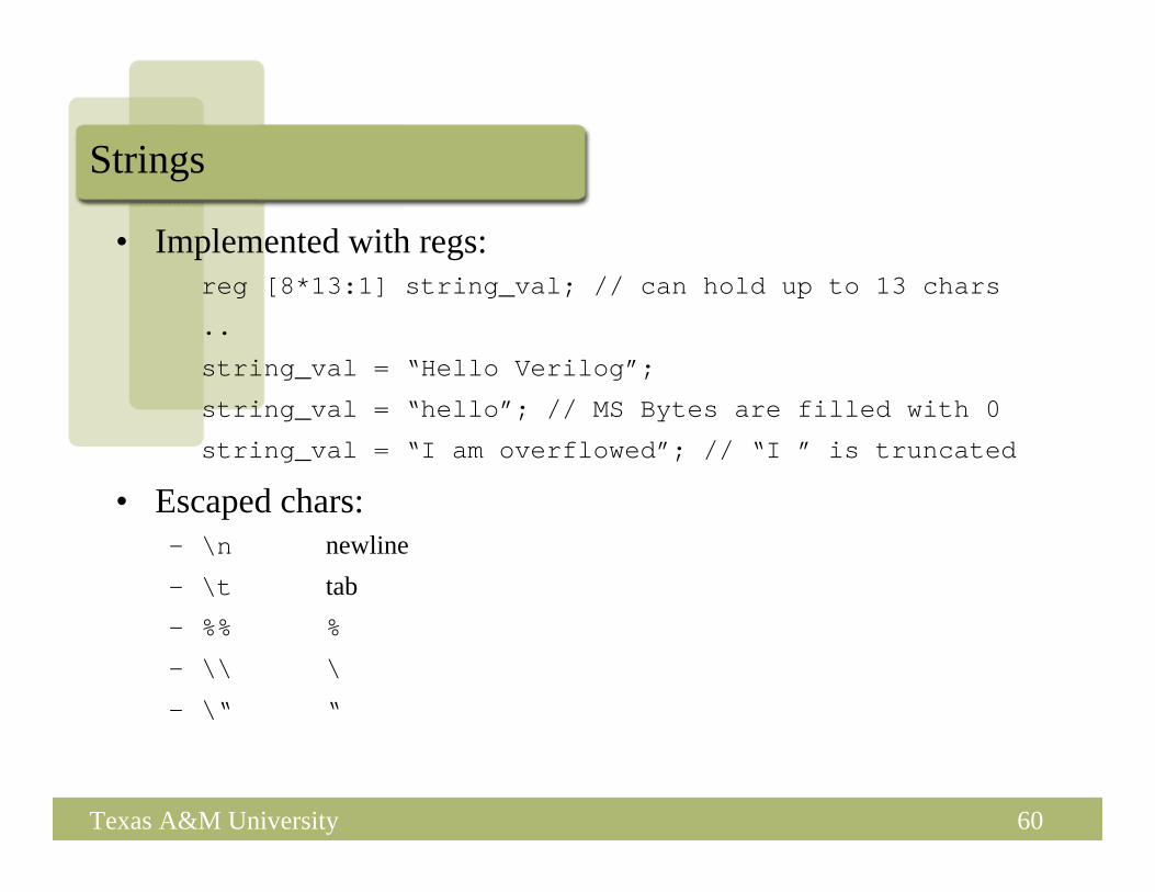
Strings
• Implemented with regs:reg [8*13:1] string_val; // can hold up to 13 chars
..
string_val = “Hello Verilog”;
string_val = “hello”; // MS Bytes are filled with 0
string_val = “I am overflowed”; // “I ” is truncated
• Escaped chars:– \n newline– \t tab– %% %
– \\ \
– \“ “

61Texas A&M University
Logical Operators
• && → logical AND• || → logical OR• ! → logical NOT• Operands evaluated to ONE bit value: 0, 1 or x• Result is ONE bit value: 0, 1 or x
A = 6; A && B → 1 && 0 → 0
B = 0; A || !B → 1 || 1 → 1C = x; C || B → x || 0 → x
but C&&B=0but C&&B=0

62Texas A&M University
Bitwise Operators (i)• & → bitwise AND• | → bitwise OR• ~ → bitwise NOT• ^ → bitwise XOR• ~^ or ^~ → bitwise XNOR
• Operation on bit by bit basis for bitwise operators.
63Texas A&M University
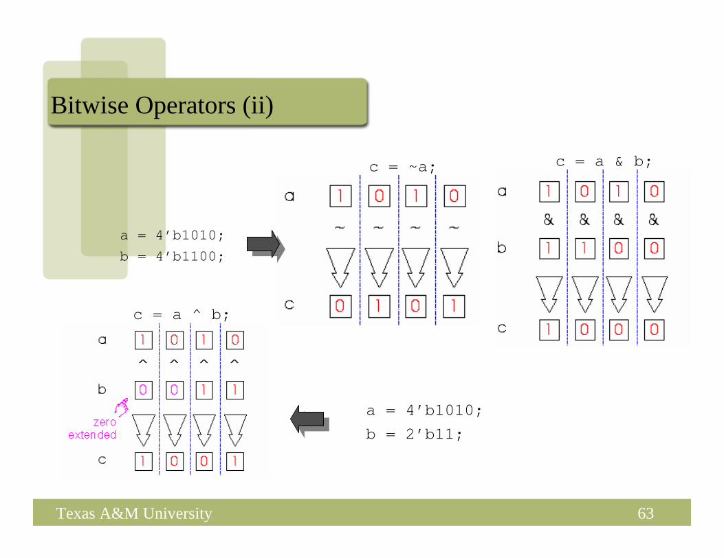
Bitwise Operators (ii)
c = ~a; c = a & b;
a = 4’b1010;
b = 4’b1100;
a = 4’b1010;
b = 2’b11;
c = a ^ b;
64Texas A&M University
Reduction Operators
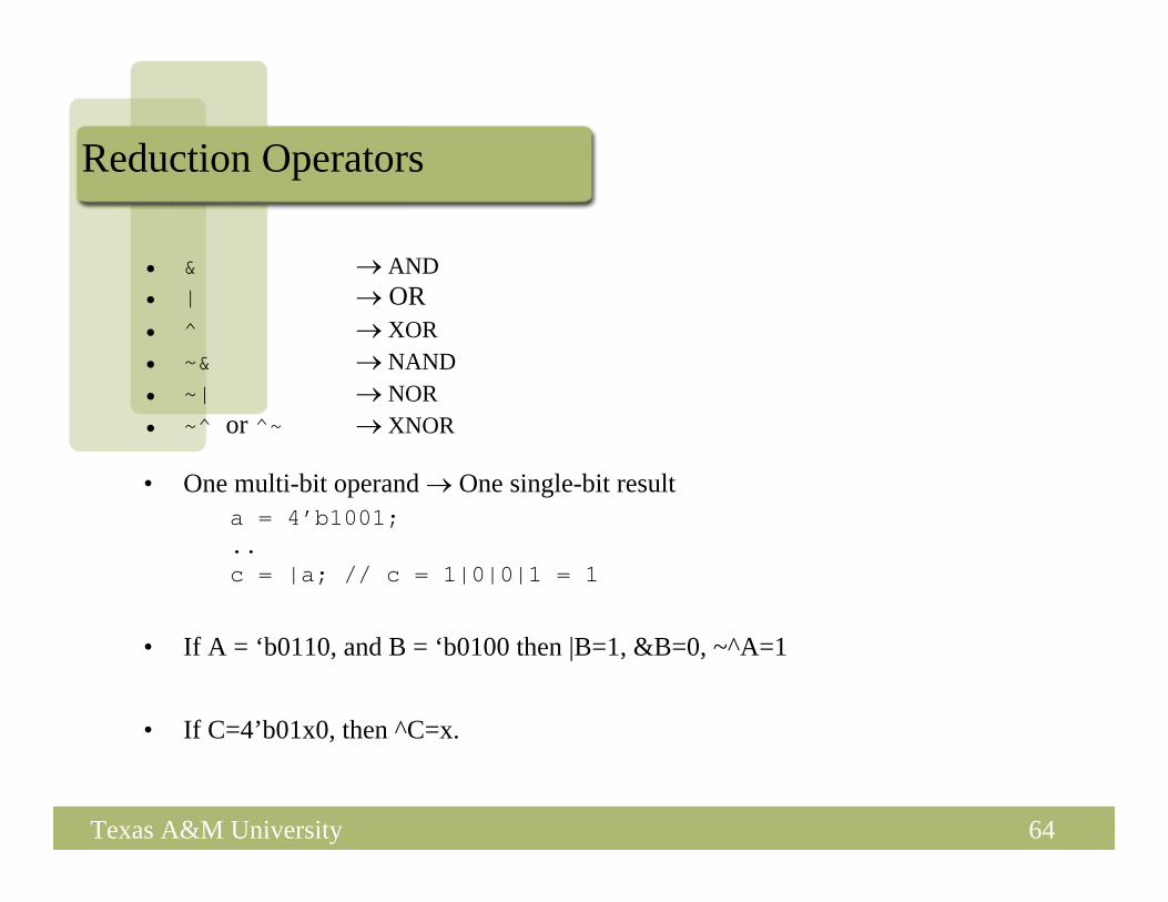
• & → AND• | → OR• ^ → XOR• ~& → NAND• ~| → NOR• ~^ or ^~ → XNOR
• One multi-bit operand → One single-bit resulta = 4’b1001; ..c = |a; // c = 1|0|0|1 = 1
• If A = ‘b0110, and B = ‘b0100 then |B=1, &B=0, ~^A=1
• If C=4’b01x0, then ^C=x.
65Texas A&M University
Shift Operators
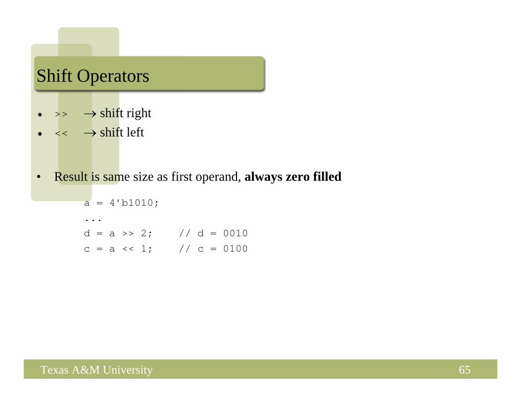
• >> → shift right• << → shift left
• Result is same size as first operand, always zero filled
a = 4’b1010;...
d = a >> 2; // d = 0010
c = a << 1; // c = 0100

66Texas A&M University
Concatenation Operator
• {op1, op2, ..} → concatenates op1, op2, .. to single number• Operands must be sized !!
reg a;
reg [2:0] b, c;..
a = 1’b 1;b = 3’b 010;c = 3’b 101;catx = {a, b, c}; // catx = 1_010_101caty = {b, 2’b11, a}; // caty = 010_11_1catz = {b, 1}; // WRONG !!
• Replication ..catr = {4{a}, b, 2{c}}; // catr = 1111_010_101101

67Texas A&M University
Relational Operators
• > → greater than• < → less than• >= → greater or equal than• <= → less or equal than
• Result is one bit value: 0, 1 or x1 > 0 → 1’b1x1 <= 0 → x10 < z → x

68Texas A&M University
Equality Operators
• == → logical equality• != → logical inequality• === → case equality• !== → case inequality
– 4’b 1z0x == 4’b 1z0x → x
– 4’b 1z0x != 4’b 1z0x → x– 4’b 1z0x === 4’b 1z0x → 1– 4’b 1z0x !== 4’b 1z0x → 0
Return 0, 1 or x
Return 0 or 1

69Texas A&M University
Conditional Operator
• cond_expr ? true_expr : false_expr
• Like a 2-to-1 mux ..
A
BY
sel
Y = (sel)? A : B;0
1

70Texas A&M University
Arithmetic Operators (i)
• +, -, *, /, %
• If any operand is x the result is x
• Negative registers:
– regs can be assigned negative but are treated as unsignedreg [15:0] regA;
..
regA = -4’d12; // stored as 216-12 = 65524
regA/3 evaluates to 21861

71Texas A&M University
Arithmetic Operators (ii)
• Negative integers:
– can be assigned negative values
– different treatment depending on base specification or notreg [15:0] regA;
integer intA;
..
intA = -12/3; // evaluates to -4 (no base spec)
intA = -’d12/3; // evaluates to 1431655761 (base spec)

72Texas A&M University
Verilog Operators

73Texas A&M University
Operator Precedence
Use parentheses to enforce your
priority

74Texas A&M University
Verilog Variables
• wire– Variable used simply to connect components together
• reg– Variable that saves a value as part of a behavioral description– Usually corresponds to a wire in the circuit– Is NOT necessarily a register in the circuit
• usage:– Don’t confuse reg assignments with the combinational
continuous assign statement! – Reg should only be used with always blocks (sequential logic,
to be presented …)

75Texas A&M University
Verilog Module
• Corresponds to a circuit component– “Parameter list” is the list of external connections, aka “ports”– Ports are declared “input”, “output” or “inout”
• inout ports used on tri-state buses– Port declarations imply that the variables are wires
module full_addr (A, B, Cin, S, Cout);input A, B, Cin;output S, Cout;
assign {Cout, S} = A + B + Cin;endmodule
module name
inputs/outputs
ports
76Texas A&M University
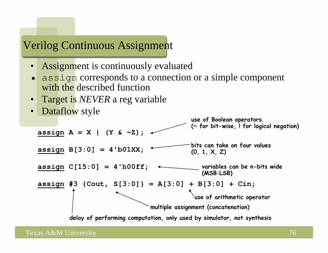
assign A = X | (Y & ~Z);
assign B[3:0] = 4'b01XX;
assign C[15:0] = 4'h00ff;
assign #3 {Cout, S[3:0]} = A[3:0] + B[3:0] + Cin;
use of arithmetic operatormultiple assignment (concatenation)
delay of performing computation, only used by simulator, not synthesis
use of Boolean operators(~ for bit-wise, ! for logical negation)
bits can take on four values(0, 1, X, Z)
variables can be n-bits wide(MSB:LSB)
Verilog Continuous Assignment
• Assignment is continuously evaluated• assign corresponds to a connection or a simple component
with the described function• Target is NEVER a reg variable• Dataflow style

77Texas A&M University
Verilog if
• Same as C if statement// Simple 4-1 muxmodule mux4 (sel, A, B, C, D, Y);input [1:0] sel; // 2-bit control signalinput A, B, C, D;output Y;reg Y; // target of assignment
always @(sel or A or B or C or D)if (sel == 2’b00) Y = A;else if (sel == 2’b01) Y = B;else if (sel == 2’b10) Y = C;else if (sel == 2’b11) Y = D;
endmodule

78Texas A&M University
Verilog if
// Simple 4-1 muxmodule mux4 (sel, A, B, C, D, Y);input [1:0] sel; // 2-bit control signalinput A, B, C, D;output Y;reg Y; // target of assignment
always @(sel or A or B or C or D)if (sel[0] == 0)if (sel[1] == 0) Y = A;else Y = B;
elseif (sel[1] == 0) Y = C;else Y = D;
endmodule

79Texas A&M University
Verilog case
• Sequential execution of cases– Only first case that matches is executed (no break)– Default case can be used
// Simple 4-1 muxmodule mux4 (sel, A, B, C, D, Y);input [1:0] sel; // 2-bit control signalinput A, B, C, D;output Y;reg Y; // target of assignment
always @(sel or A or B or C or D)case (sel)
2’b00: Y = A;2’b01: Y = B;2’b10: Y = C;2’b11: Y = D;
endcaseendmodule
Conditions tested intop to bottom order

80Texas A&M University
Verilog case
• Without the default case, this example would create a latch for Y• Assigning X to a variable means synthesis is free to assign any value
// Simple binary encoder (input is 1-hot)module encode (A, Y);input [7:0] A; // 8-bit input vectoroutput [2:0] Y; // 3-bit encoded outputreg [2:0] Y; // target of assignment
always @(A)case (A)8’b00000001: Y = 0;8’b00000010: Y = 1;8’b00000100: Y = 2;8’b00001000: Y = 3;8’b00010000: Y = 4;8’b00100000: Y = 5;8’b01000000: Y = 6;8’b10000000: Y = 7;default: Y = 3’bX; // Don’t care when input is not 1-hot
endcaseendmodule

81Texas A&M University
Verilog case (cont)
• Cases are executed sequentially– The following implements a priority encoder
// Priority encodermodule encode (A, Y);input [7:0] A; // 8-bit input vectoroutput [2:0] Y; // 3-bit encoded outputreg [2:0] Y; // target of assignment
always @(A)case (1’b1)A[0]: Y = 0;A[1]: Y = 1;A[2]: Y = 2;A[3]: Y = 3;A[4]: Y = 4;A[5]: Y = 5;A[6]: Y = 6;A[7]: Y = 7;default: Y = 3’bX; // Don’t care when input is all 0’s
endcaseendmodule

82Texas A&M University
Parallel case
• A priority encoder is more expensive than a simple encoder– If we know the input is 1-hot, we can tell the synthesis tools– “parallel-case” pragma says the order of cases does not matter
// simple encodermodule encode (A, Y);input [7:0] A; // 8-bit input vectoroutput [2:0] Y; // 3-bit encoded outputreg [2:0] Y; // target of assignment
always @(A)case (1’b1) // synthesis parallel-caseA[0]: Y = 0;A[1]: Y = 1;A[2]: Y = 2;A[3]: Y = 3;A[4]: Y = 4;A[5]: Y = 5;A[6]: Y = 6;A[7]: Y = 7;default: Y = 3’bX; // Don’t care when input is all 0’s
endcaseendmodule
83Texas A&M University
Verilog casex
• Like case, but cases can include ‘X’– X bits not used when evaluating the cases– In other words, you don’t care about those bits!

84Texas A&M University
casex Example// Priority encodermodule encode (A, valid, Y);input [7:0] A; // 8-bit input vectoroutput [2:0] Y; // 3-bit encoded outputoutput valid; // Asserted when an input is not all 0’sreg [2:0] Y; // target of assignmentreg valid;
always @(A) beginvalid = 1;casex (A)
8’bXXXXXXX1: Y = 0;8’bXXXXXX10: Y = 1;8’bXXXXX100: Y = 2;8’bXXXX1000: Y = 3;8’bXXX10000: Y = 4;8’bXX100000: Y = 5;8’bX1000000: Y = 6;8’b10000000: Y = 7;default: begin
valid = 0;Y = 3’bX; // Don’t care when input is all 0’s
endendcase
endendmodule

85Texas A&M University
Verilog for
• for is similar to C• for statement is executed at compile time (like macro expansion)
– Useful for parameterized designs.// simple encodermodule encode (A, Y);input [7:0] A; // 8-bit input vectoroutput [2:0] Y; // 3-bit encoded outputreg [2:0] Y; // target of assignment
integer i; // Temporary variables for program onlyreg [7:0] test;
always @(A) begintest = 8b’00000001;Y = 3’bX;for (i = 0; i < 8; i = i + 1) begin
if (A == test) Y = N;test = test << 1;
endend
endmodule

86Texas A&M University
Verilog while/repeat/forever
• while (expression) statement– Execute statement while expression is true
• repeat (expression) statement– Execute statement a fixed number of times
• forever statement– Execute statement forever

87Texas A&M University
full-case and parallel-case
• // synthesis parallel_case– Tells compiler that ordering of cases is not important– That is, cases do not overlap
• e. g., state machine - can’t be in multiple states– Gives cheaper implementation
• // synthesis full_case– Tells compiler that cases left out can be treated as don’t cares– Avoids incomplete specification and resulting latches